Abstract
Alumina dispersion-strengthened 316L stainless steels were successfully produced using attrition milling and spark plasma sintering. Two different composites (316L/0.33 wt% and 316L/1 wt% Al2O3) were prepared by powder technology. The attrition milling produced a significant morphological transformation of the globular 316L starting powders and provided a homogeneous distribution of the nanosized alumina particles. The XRD results confirmed that the 316L steel was an austenitic γ-Fe3Ni2. The formation of a ferrite α-Fe phase was detected after milling; this was transformed to the austenitic γ-Fe3Ni2 after the sintering process. The addition of nanosized alumina particles increased the composites’ microhardness significantly to 2.25 GPa HV. With higher amounts of alumina, the nanosized particles tended to agglomerate during the milling process. The friction coefficient (FC) of the 316L/0.33 wt% Al2O3 and the 316L/1 wt% Al2O3 decreased because of the increase in the composite’s hardness; FC values of 0.96, 0.93 and 0.85, respectively, were measured respectively for the 316L reference, the 316L/0.33 wt% and the 316L/1 wt% Al2O3. The 316L/0.33 wt% Al2O3 composite had a higher flexural strength of 630.4 MPa compared with the 316L/1 wt% Al2O3 with 386.6 MPa; the lower value of the latter was related the agglomeration of the alumina powder during attrition milling.
1. Introduction
The increasing demand for more economically profitable and safer reactors directly imposes the great need for the development of new materials that can withstand extreme and aggressive working conditions and provide a reactor with a longer working life [1]. The development of new materials for future nuclear reactors imposes the need to develop the manufacturing processes as well as assessments of the performance [2]. The compatibility of the construction material’s properties and the working conditions of the nuclear reactors are still major concerns for the long-term safety and environmental degradation [3]. Currently, material scientists are facing major challenges imposed by the increasing need for novel materials that can withstand the extreme working conditions of the future generations of nuclear reactors [4], such as fusion and fission nuclear power [5], and this is a priority because any material failure can result in a severe accident [6]. Viswanathan et al. reported the challenges and advances in nanocomposite processing techniques, and that the manufacturing process of the materials has a direct impact on their final properties. The traditional sintering processes involved in powder technology are known for their inability/limitations in retaining nanosized particles in the final product/material. On the other hand, powder metallurgy is a key factor for developing new nanotechnology materials for different industries and applications such as medicines, engineering and energy. The nanocomposite materials are known for their ability to provide greatly enhanced mechanical, chemical and physical properties that are currently in great demand for advanced applications in cutting-edge technologies [7]. Nanosized materials have been attracting more attention recently and different manufacturing processes are in use for their development, parallel to investigations of their corrosion resistance [8]. It is well known that mechanical alloying (MA) is an effective and easy process of obtaining nanosized microstructures with a higher content of reinforcement phases. MA allows for controlled homogeneous distribution of the particles in the grain boundaries; moreover, it is possible to obtain fully dense composites with enhanced mechanical properties [9]. The oxide dispersion-strengthened (ODS) steels are promising candidates as structural materials for application in advanced nuclear reactors because of their higher radiation resistance and enhanced mechanical properties [10,11]. The thermally stable oxide particles imbedded in the ODS steels provide massively enhanced mechanical properties. On the other hand, the general disadvantage of powder metallurgy technology is the relatively time-consuming manufacturing/preparation of the powders [12]. Xiang Long Guo et al. reported that ODS composites with a high Cr content have a good corrosion resistance in supercritical water reactors [13]. Other research has shown that post-process treatments can significantly reduce the density of cracks in the materials produced [14].
Ben Zine et al. investigated the addition of SiC and Si3N4 to 316L stainless steel produced by attrition milling and spark plasma sintering (SPS).
In our previous studies, both 316L/0.33 wt% SiC and 316L/1 wt% SiC composites showed similar grain morphologies with flake-like grains after milling, and the SiC particles were homogeneously dispersed and covered the steel grains. The addition of the SiC particles significantly increased the 316L steel’s microhardness. The complex grain boundaries created higher crack propagation resistance during the three-points bending test, where a combination of intergranular and transgranular crack propagation has been observed during investigation of the fractures’ surfaces by SEM [15].
In the case of the 316L/Si3N4, due to the agglomeration of silicon nitride during the milling process, powder mixtures with different grain sizes and shapes of 316L stainless steel were obtained after milling in the case of the 316L/1 wt% Si3N4, whereas more uniform flake-like grains with different sizes were obtained in the case of the 316L/0.33 wt% Si3N4. The Si3N4 particles’ distribution along the grain boundaries of the sintered samples were observed by TEM. The different grain morphologies and the agglomeration of Si3N4 in the case of 316L/1 wt% Si3N4 directly affected the microhardness and the flexural strength of the sintered composite, where lower values were measured in comparison with the 316L/0.33 wt% Si3N4 [16]. Recently, many researchers have intensively developed and investigated aluminium-containing alloys/composites as promising construction candidates for future nuclear reactors [17,18].
The corrosion of the structured and fuel is a major problem in the development of heavy liquid metal cooled nuclear energy and transmutation reactors. As a solution to this problem, a protective stable oxide layer is needed. Weisenburger et al. reported that alloying stable oxide formers into the surface is a suitably efficient procedure for protecting the base material. With a content of 4–10% aluminium, a thin, stable and protective layer formed on the surface as a result of the diffusion of aluminium. The slowly formed layer acted as double-sided barrier, which prevented oxygen’s migration to the steel; on the other side, it keeps the steel’s components from migrating to the surface [19]. The formation of a dense alumina layer or aluminium-modified Cr2O3 on the surface can provide good resistance against corrosion and oxidation to many Fe and Ni based alloys [20,21,22]. The resistance of the Al-Fe coating against corrosion increases with the formation of the LiAlO2 layer; however, this protective layer is not permanent, as it degrades as a result of an insufficient amount of aluminium in the Al-Fe coating. The results show that the minimum amount needed to maintain the protective layer should be between 25% and 36% [23]. Pawel et al. observed that the samples which had been exposed to temperatures above 500 °C lost mass, which may indicate that the alumina-rich film was not completely stable; as a result, it may increase the incubation time which is associated with dissolution and wetting [24]. The FeCrAl-ODS currently being studied is a safer material and a promising candidate as a construction material for the cladding of light water reactors and as an accident=tolerant fuel. One of the main advantages is the formation of a protective alumina layer [6,17,25]. However, ferritic alloys with a high content of Al and Cr tend to become brittle during the manufacturing and service process as a result of the formation of brittle phases. A study showed that FeCrAl composites with low chromium and high aluminium contents have better properties compared with the FeCrAl alloys with a higher Cr and lower Al content [26]. The formation of massive Al2O3 particles in the grain boundaries partially suppresses the spinodal decomposition, which results in the formation of the FCC phase at high sintering temperatures [11]. The formation of alumina particles is possible during the mechanical alloying process [27]. Low-temperature sintering is essential for the homogeneous distribution of the nanosized FeAl2O4 within the FeAl matrix [28]. The 16Cr-3Al ODS composites showed better corrosion resistance compared with 16Cr ODS composites because of the formation of a double layer of Al2O3 and a Cr2O3 and Al2O3 layer on top of it. The diffusion rate of oxygen was decreased significantly [29]. The protection of the base material against microstructural degradation and elemental dissolution was possible through the formation of the alumina layer on top of the aluminide layers through controlled thermal cycling; on the other hand, the formation of self-healing oxides in/between the aluminide scales during thermal cycling was observed [30]. The addition of Al particles could significantly increase the ductility but it decreased the strength of the 9Cr-ODS steel because of the formation of large nanosized Y-Al-O particles [31]. Other research has shown that it is possible to increase the corrosion resistance of austenitic steels by adding aluminium [32].
Other researchers have investigated improvements in the wear and corrosion resistance by incorporating hard particles into coatings using different techniques such as plasma electrolytic oxidation (PEO). Pezzato et al. showed that the tribological properties and corrosion resistance could be improved through the deposition of a composite layer containing hard particles such as SiC or borosilicate glass particles by plasma electrolytic oxidation (PEO). It was found that a 3 min treatment time with the addition of glass particles provided the best results in terms of corrosion and wear resistance [33]. Bahramian et al. found that the addition of nanosized Al2O3/TiO2 particles increased the density of the coating deposited by PEO, and increased its corrosion resistance, hardness and fracture toughness [34]. In addition, Arrabal et al. found that the outer layer of PEO coatings containing α-Al2O3 particles showed lower porosity, increased hardness and the lowest wear volumes of all the materials tested [35].
The ability to protect steel alloys by forming a superficial thin layer of alumina can be achieved through the addition of aluminium to the composition [19] or by coating [23]. These experiments have shown good and promising results. However, the protective layer is subject to degradation over time, and the material is again exposed to the extreme working conditions [23]. Alumina-forming alloys (AFA) have recently attracted more attention because Al2O3 exhibits a lower growth rate and is more thermodynamically stable in oxygen than Cr2O3 and it is highly stable in water vapor. Adding aluminium creates major strengthening problems, as it is a stabilizer of a BCC structure and facilitates the formation of the delta ferrite; it also compromises the strength by interfering with the addition of nitrogen [36]. The use of other elements as co-dopants has shown promising results in terms of slowing the growth of scales and their adhesion, which will enhance the lifetime of the material [37].
The goal of our approach was to create a protective alumina layer in the grain boundaries, starting from embedded and stable ultra-fine alumina (Al2O3) powders instead of adding aluminium (Al) powders or Al-Fe coatings, as mentioned in most of the research conducted recently on this topic. We assumed that the addition of alumina powders would possibly provide better and longer protection for the steel composites because of its distribution along the grain boundaries and would solve the problem of the insufficient content of aluminium in the Al-Fe coating for the formation of a protective layer, as the Al2O3 was already formed. Moreover, alumina is more thermodynamically stable at the sintering temperature and allows for better control of sintering by avoiding the infiltration of aluminium during the sintering process.
2. Experimental Methods
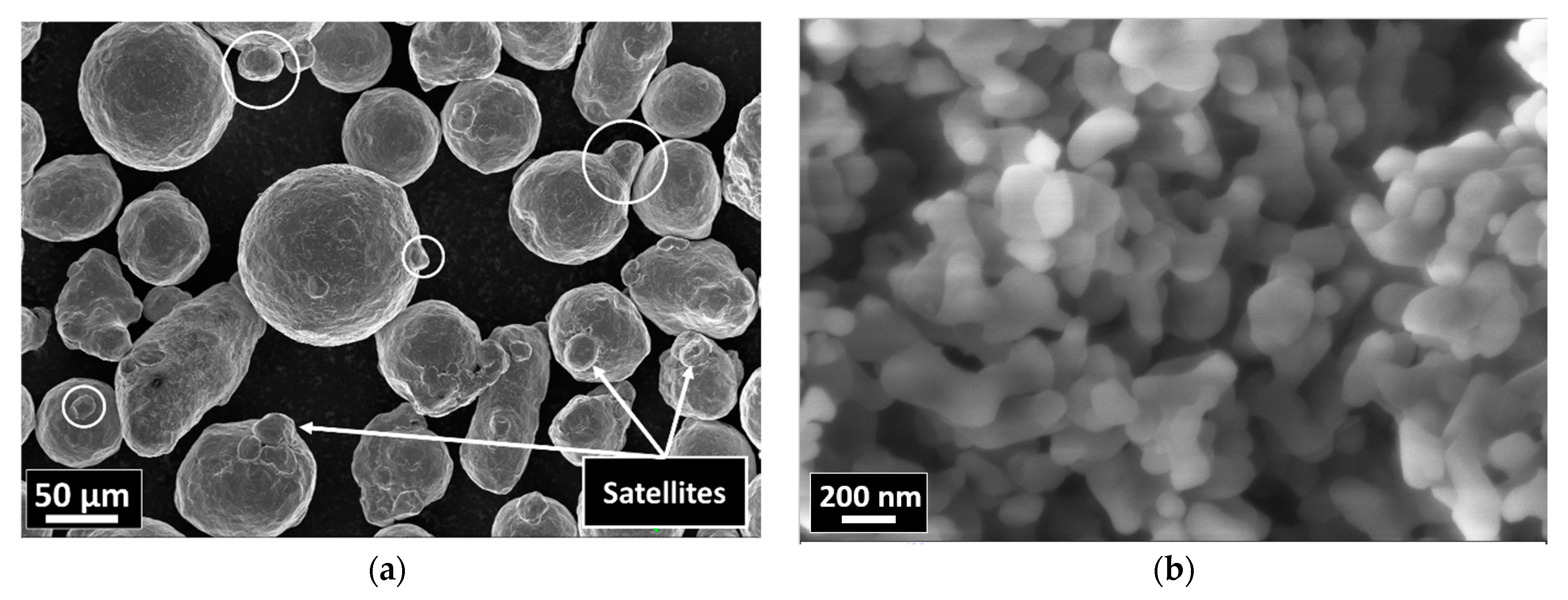
A commercial austenitic 316L stainless steel (Höganäs, Sweden) with a composition of 16.8Cr–12Ni–2.5Mo–1.5Mn–0.6Si and an average particle size of ~70 μm (Figure 1a) was milled separately (reference sample) and together with the ultra-fine Al2O3 powders (Almatis GMBH) with average grain size of ~200 nm (Figure 1b). Attrition milling (Union Process type 01-HD/HDDM) was used for dispersion of the Al2O3 particles in the steel matrix and for simultaneously reducing the size of the 316L steel’s grains at 600 rpm in ethanol for 5 h. A stainless steel tank and agitator and grinding media 3 mm in diameter were used for milling. Spark plasma sintering (SPS, Sinter-SPS-7.40MK-VII, Fuji Electronic Ind. Co., Japan) was used for sintering the milled powders at 900 °C under 50 MPa of mechanical pressure for 5 min in a vacuum (6 Pa). Sintered solid disks ~100 mm in diameter and ~9 mm in thickness were obtained. INSTRON 2500 apparatus (Norwood, MA, USA) equipped with a special 3-point bending test setup was used to measure the flexural strength of the samples, for which 5 samples of each composite with dimensions of 4 mm × 4 mm × 25 mm were polished and their edges were rounded in order to minimize the possibility of cracks propagating from a surface defect. The tribological properties of the sintered samples were determined at room temperature in dry conditions using a CSM + HT Tribometer. Different grinding papers (grades up to 100 μm) were used for polishing the samples before measuring the tribological properties. A normal load of 5 N was applied to the counterpart Si3N4 balls (5 mm in diameter) on the steel samples’ surface with a 1 mm shift from the axis of rotation of the sample. Scanning electron microscopy (SEM, Zeiss-SMT LEO 1540 XB,) was used for structural and morphological investigations of the base powder, and the milled and sintered samples. The elemental composition of the sintered samples was measured by energy dispersive spectroscopy (EDS) equipment installed on an SEM LEO microscope. Phase analyses were performed by a X-ray diffractometer (XRD, Bruker AXS D8) equipped with a Göbel mirror and a scintillation detector with Cu Kα (λ = 1.5406 Å) radiation. The X-ray beam’s dimensions were 1 mm × 5 mm, the 2θ step size was 0.02°, and the scan speed was 0.3°/min. We used the Diffrac.EVA program and the ICDD PDF database for phase identification. The hardness of the sintered alumina dispersion-strengthened steel composites was measured by the Vickers method on 5 samples of each composite with an applied load of 5 N for 30 s.
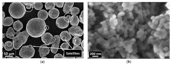
Figure 1.
SEM images of the starting powders: (a) 316L; (b) Al2O3.
3. Results and Discussion
3.1. Morphological and Structural Investigation
The morphological investigation of the starting powders confirmed that the 316L stainless steel grains had a globular shape with an average particle size of ~70 μm and the presence of satellites (Figure 1a). The nanosized alumina particles had an average diameter of ~200 nm (Figure 1b).
After intensive wet attrition milling, the globular 316L stainless steel grains were severely deformed/flattened under a combination of the impact and shear forces generated between the agitator and the steel milling balls. The milled composites with 0.33 wt% Al2O3 (Figure 2a) the 1 wt% Al2O3 (Figure 2b) showed similar morphologies after 5 h of wet attrition milling. Three different grain shapes can be clearly observed in both composites: (1) flattened grains, (2) thin flake-like grains and (3) small broken flake-like grains (Figure 2).
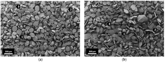
Figure 2.
SEM images of the milled composites: (a) 316L/0.33 wt% Al2O3; (b) 316L/1 wt% Al2O3.
The surface of the milled steel grains of both composites were investigated by EDS. Multiple spots were randomly selected in different grains to study the distribution of the nanosized Al2O3 particles in the grains’ surfaces (Figure 3 and Figure 4).
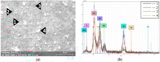
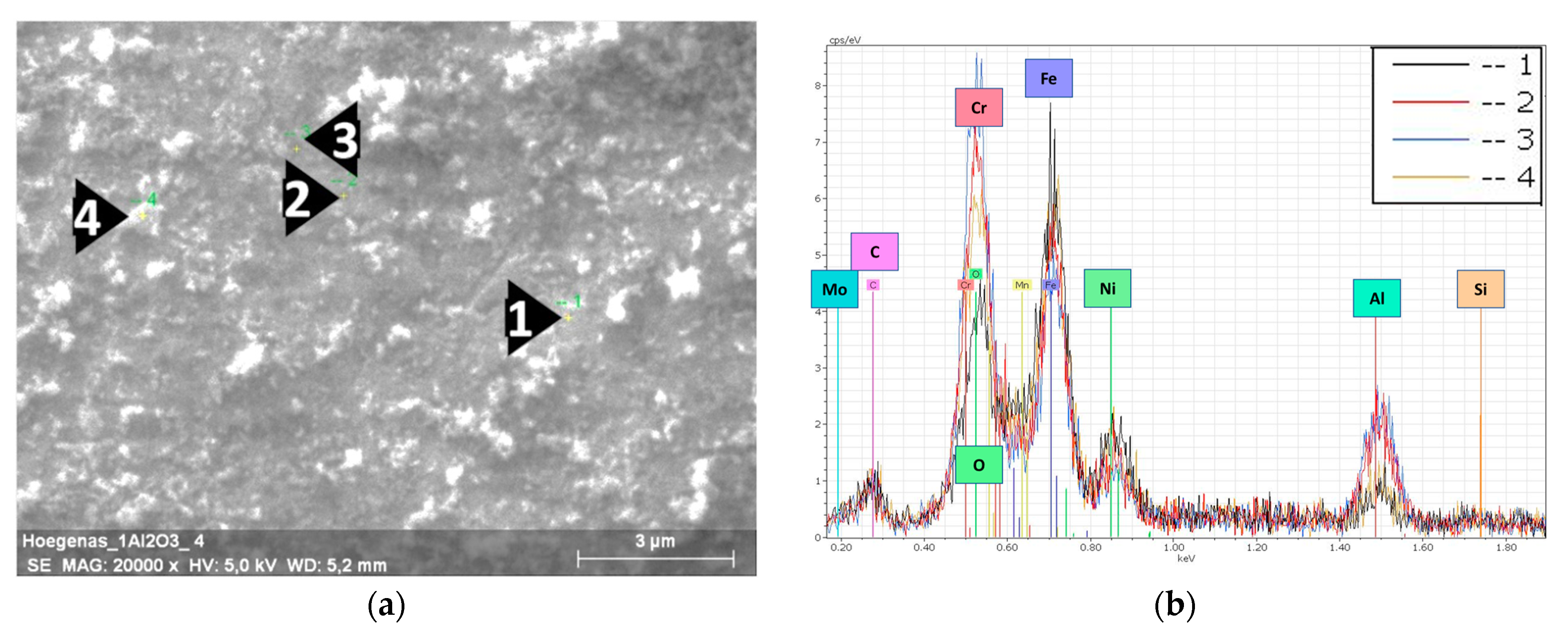
Figure 3.
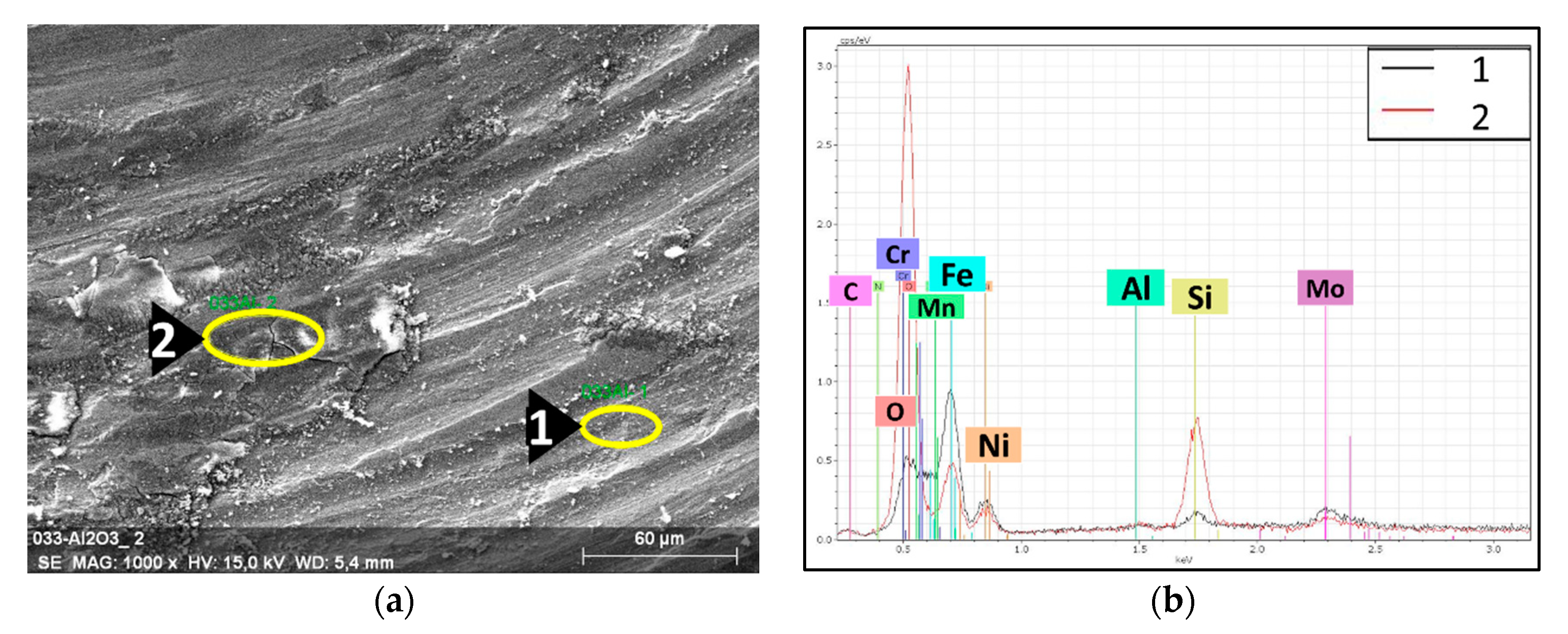
EDS results of the milled 316L/0.33 wt% Al2O3. (a) SEM image of a 316L grain’s surface; (b) EDS spectra of the selected spots.
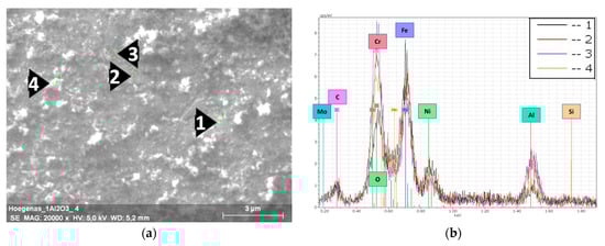
Figure 4.
EDS results of the milled 316L/1 wt% Al2O3. (a) SEM image of a 316L grain’s surface; (b) EDS spectra of the selected spots.
Figure 3a shows the selected spots and the corresponding EDS spectra (Figure 3b) of the investigated 0.33 wt% Al2O3 composite. The dark spots embedded in the grains’ surface (Spots 2 and 3 in Figure 3a) are nanosized Al2O3 particles. The EDS spectra of these spots showed higher peaks of aluminium and oxygen. From the distribution of the dark spots and the lower peaks of Fe and Ni in them compared with the 316L grains’ surface (Spot 1), we can state/conclude that the nanosized Al2O3 particles were homogeneously distributed and relatively covered the surfaces of the 316L steel grains. The particles on the top of the grains’ surface (Spot 4 in Figure 3) are debris from the broken flake-like grains. The corresponding EDS spectra of Spot 4 shows that these small white particles are oxidized 316L particles. This oxidation was a result of the combination of (1) the severe plastic deformation that introduced high mechanical stress to the steel particles and (2) the exposure to ethanol during the wet milling process.
In the case of the 1 wt% Al2O3 milled powders (Figure 4), the steel grains’ surfaces were totally covered by the embedded nanosized alumina particles. Distinguishing and selecting individual alumina particles was not possible, as the nanosized particles fully covered the steel grains and resulted in a darker thin layer of alumina compared with the distributed and fragmented dark spots in Figure 3a. The formation of this thin layer was in agreement with the study of Jun Lim et al. on the design of alumina for forming FeCrAl steels for lead or lead–bismuth cooled fast reactors. These authors concluded that the minimum amount of Al necessary to form a protective layer should be more than 0.50 wt% [26]; however, the thickness of this alumina layer was not consistent/uniform. This can be observed from the EDS peaks intensity of the different spots. This result can be related to the tendency of alumina particles to agglomerate during the milling process. The presence of a higher amount of the white debris (oxidized 316L particles) from the broken flake-like grains on the surface was observed.
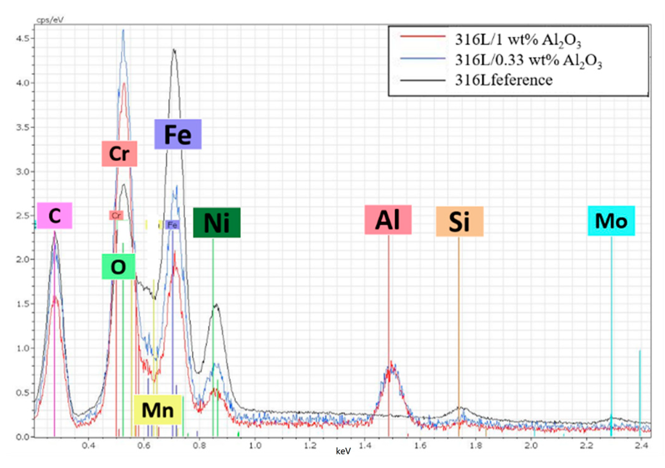
Figure 5 is a comparison of the EDS spectra of the 316L, 316L/0.33 wt% Al2O3 and the 316L/0.33 wt% Al2O3 sintered composites. The high intensity of the aluminium and oxygen peaks confirmed the presence of alumina in both composites after sintering. On the other hand, the lower intensity of the 316L components’ peaks (Fe, Ni) in the 316L/1 wt% Al2O3 composite compared with the 316L/0.33 wt% Al2O3 and the reference alloys confirmed the formation of a thin Al2O3 layer covering the 316L grains. In the case of the 316L/0.33 wt% Al2O3, the EDS spectra showed good coverage and the homogeneous distribution of the alumina particles in the 316L stainless steel matrix.
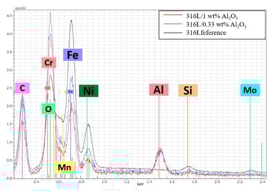
Figure 5.
Comparison of the EDS spectra of the sintered composites.
The presence of the oxidized 316L debris (Figure 3a and Figure 4a) on the grains’ surfaces was in favour of the formation of Cr2O3 scales/layers, as it provides a higher amount of oxygen along the grain boundaries. The formation of the Cr2O3 scales/layer is highly possible, as this was indicated in other research [27,28]. However, as the EDS peaks of chromium and oxygen overlapped, further investigations are needed in order to confirm it.
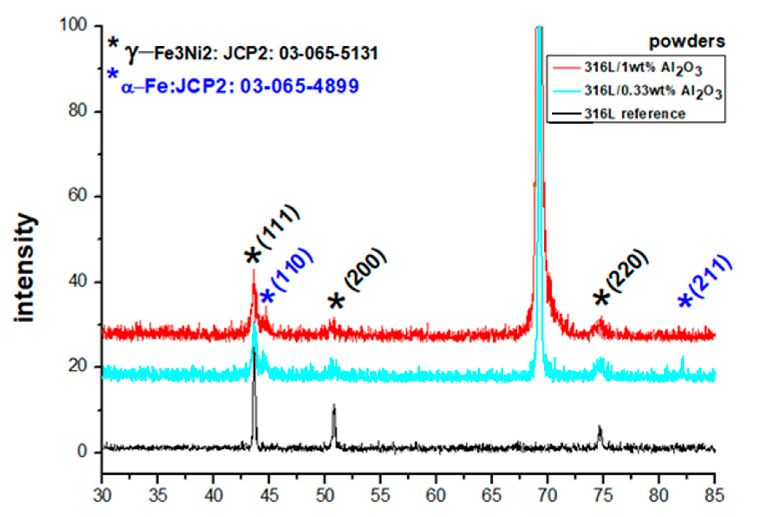
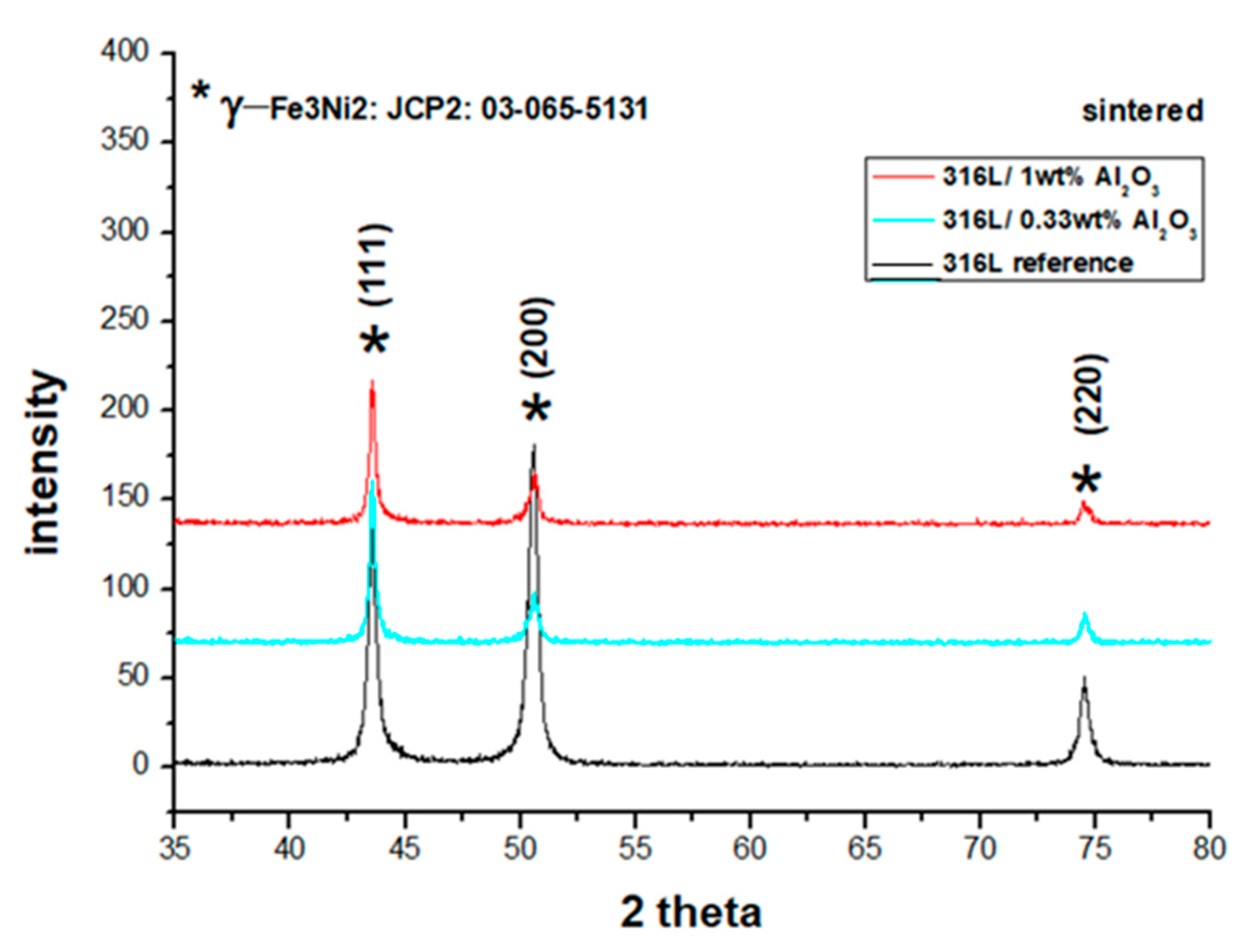
A comparison of the XRD diffraction patterns of the starting powders and the milled powders (Figure 6) confirmed that the powders had a crystalline structure of an FCC γ-Fe3Ni2 phase (JPC2:03-065-5131) with the main lines 2θ = 43.532°, 50.705° and 74.535°, corresponding to the diffracted planes (111), (200) and (220), respectively. The BCC Fe alpha phase (JPC2:03-065-4899) with the main lines of 2θ = 44.663° and 82.314° corresponding to the diffracted planes (110) and (211), respectively, formed after milling. The starting powders had the main lines of 2θ = 43.576°, 50.759° and 74.594°,with an average deviation of 0.052° to the right from the JPC2:03-065-5131 lines. The 316L/0.33 wt% Al2O3 milled powders had the main lines of 2θ = 43.576°, 50.605° and 74.575°, with an average deviation of 0.005° from the corresponding JPC2:03-065-5131 lines. The first and third peaks shifted to the right, and the second peak shifted to the left. Two main peaks of an alpha phase corresponding to the Fe alpha JPC2:03-065-4899 were detected as follows: 2θ = 44.522° and 82.106°. The 316L/1 wt% Al2O3 milled powders had the main lines of 2θ = 43.552°, 50.746° and 74.653°, with an average deviation of 0.060° to the right of the corresponding JPC2:03-065-5131 lines. Two main peaks of an alpha phase corresponding to the Fe alpha JPC2:03-065-4899 were detected as follows: 2θ = 44.659° and 82.215°.
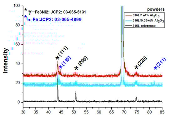
Figure 6.
XRD diffractograms of the 316L reference powder, the milled 316L/0.33 wt% Al2O3 and the milled 316L/1 wt% Al2O3.
The formation of a small fraction of the α phase was related to a partial phase transformation induced by the severe plastic deformation during the milling process. The formation of a similar α phase after milling was observed in our previous work on Si3N4 [16] and SiC [15] dispersion-strengthened 316L steel. Al-Joubori et al. observed the formation of a similar α phase [38].
By comparing the XRD results in Figure 6, we can observe that grain size of both milled powders was smaller than the globular grains of the starting reference 316L steel.
The ferrite α-Fe phase was transformed to austenitic γ-Fe3Ni2 after sintering (Figure 7). No FeAl or Al phases were detected. This result is in agreement with the Fe-Al binary phase diagram, which indicated that there was no FeAl phase formation for alloys under 21% of aluminium [39].
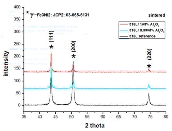
Figure 7.
XRD diffractograms of the sintered composites: the reference 316L, the 316L/0.33 wt% Al2O3 and the 316L/1 wt% Al2O3.
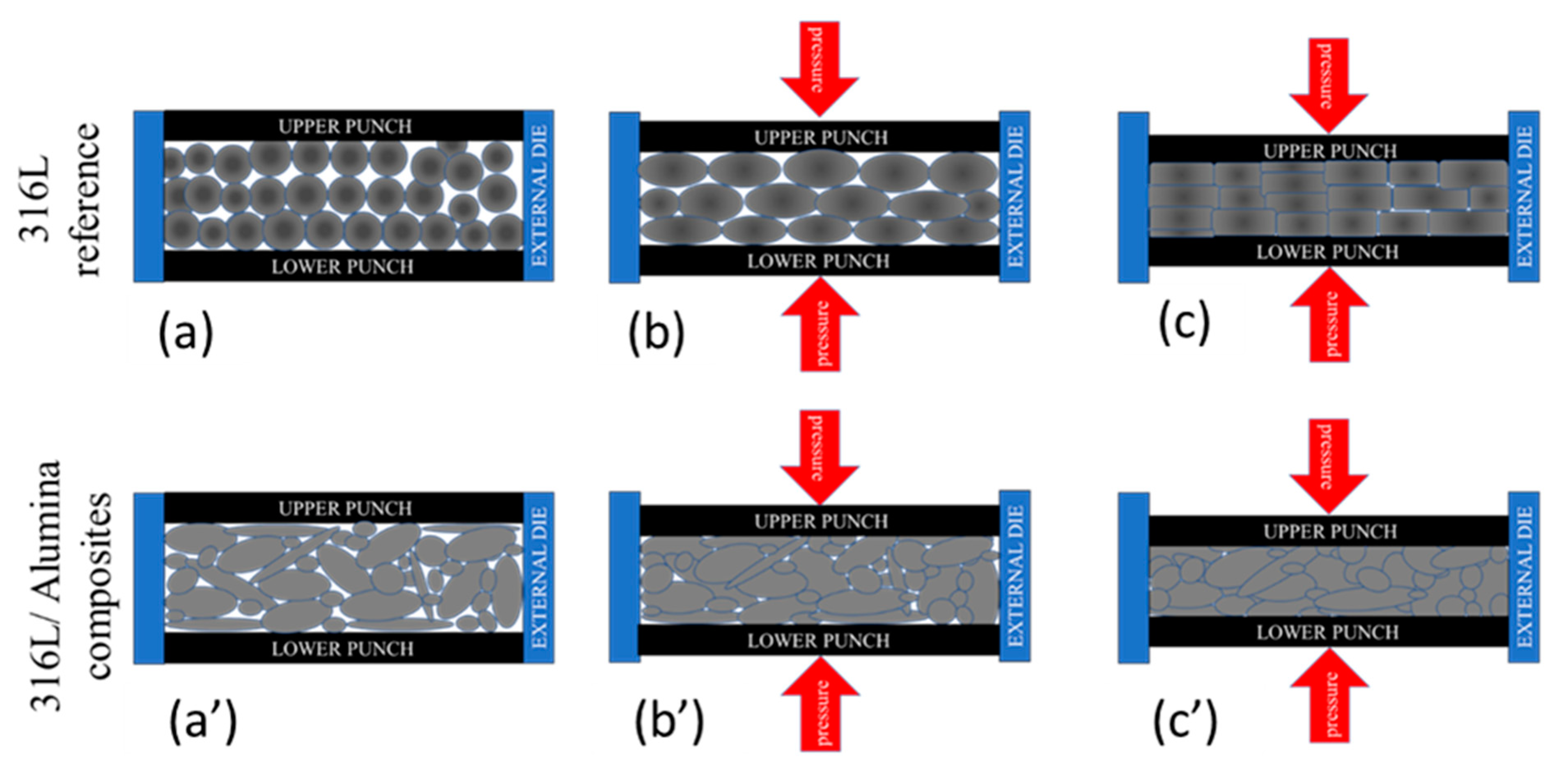
The sintered 316L sintered composite had the main lines of 2θ = 43.533°, 50.624° and 74.537° with an average deviation of 0.026° from the corresponding JPC2:03-065-5131 lines. Unlike the other sintered composites, the grains were preferentially distributed along with the (200) orientation (2θ = 50.624°), as can be observed from the peak intensity. This preferential crystallographic orientation is mainly related to a texture effect in the diffracted surface; similar behaviour was studied by Marattukalam et al. in their study on the effect of laser scanning strategies on the textural and mechanical properties, and site-specific grain orientation in selective laser-melted 316L SS [40]. This texture is a result of the globular grains’ deformation during the sintering process, as illustrated in Figure 8. The globular grains of 316L were flattened and elongated parallel to the upper and lower punches’ surfaces (Figure 8a–c). In the case of the 316L/0.33 wt% Al2O3 and 316L/1 wt% Al2O3, no texturing behaviour was observed because of the presence of different grain morphologies and sizes. These grains were harder because of plastic deformation during the milling process; on the other hand, the milled powders were randomly arranged and the small broken grains filled the spaces between the larger grains and minimised the plastic deformation by limiting the displacement of grains under pressure (Figure 8a’–c’).
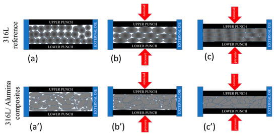
Figure 8.
Schematic representation of the grains’ texture under plastic deformation during the sintering process. (a,a’) Initial arrangement; (b,b’) applying pressure; (c,c’) sintered sample under pressure.
The sintered 316L/0.33 wt% Al2O3 samples had the main lines of 2θ = 43.536°, 50.692° and 74.536°, with an average deviation of 0.003° from the corresponding JPC2:03-065-513 lines. The sintered 316L/1 wt% Al2O3 had the main lines of 2θ = 43.547°, 50.660° and 74.539°, with an average deviation of 0.009° from the corresponding JPC2:03-065-513 lines. In all sintered composites, we observed that both the first (111) and the third (220) peaks shifted to the right, and the second peak (200) shifted to the left in comparison with the JPC2:03-065-5131 peaks.
It was proven by Chattopadhyay et al. in their study on the microstructure/phase evolution in mechanical alloying/milling of stainless steel and aluminium powder blends that no considerable changes in the lattice parameters of the face-centred cube structure were observed in 316L alloys with an aluminium percentage lower than 25 wt% [41]. Therefore, we assumed that the observed shifts of the diffracted peaks in all of the powders and sintered composites did not indicate any significant changes/distortions of the 316L FCC matrix.
3.2. Investigation of the Density and Mechanical Properties
The sintered reference 316L, the 316L/0.33 wt% Al2O3 and the 1 wt% Al2O3 composites showed high densities of 99.13%, 97.88% and 96.13%, respectively. The lower density values of the 316L/0.33 wt% Al2O3 and the 1 wt% Al2O3 composites compared with the 316L composite were related the addition of alumina.
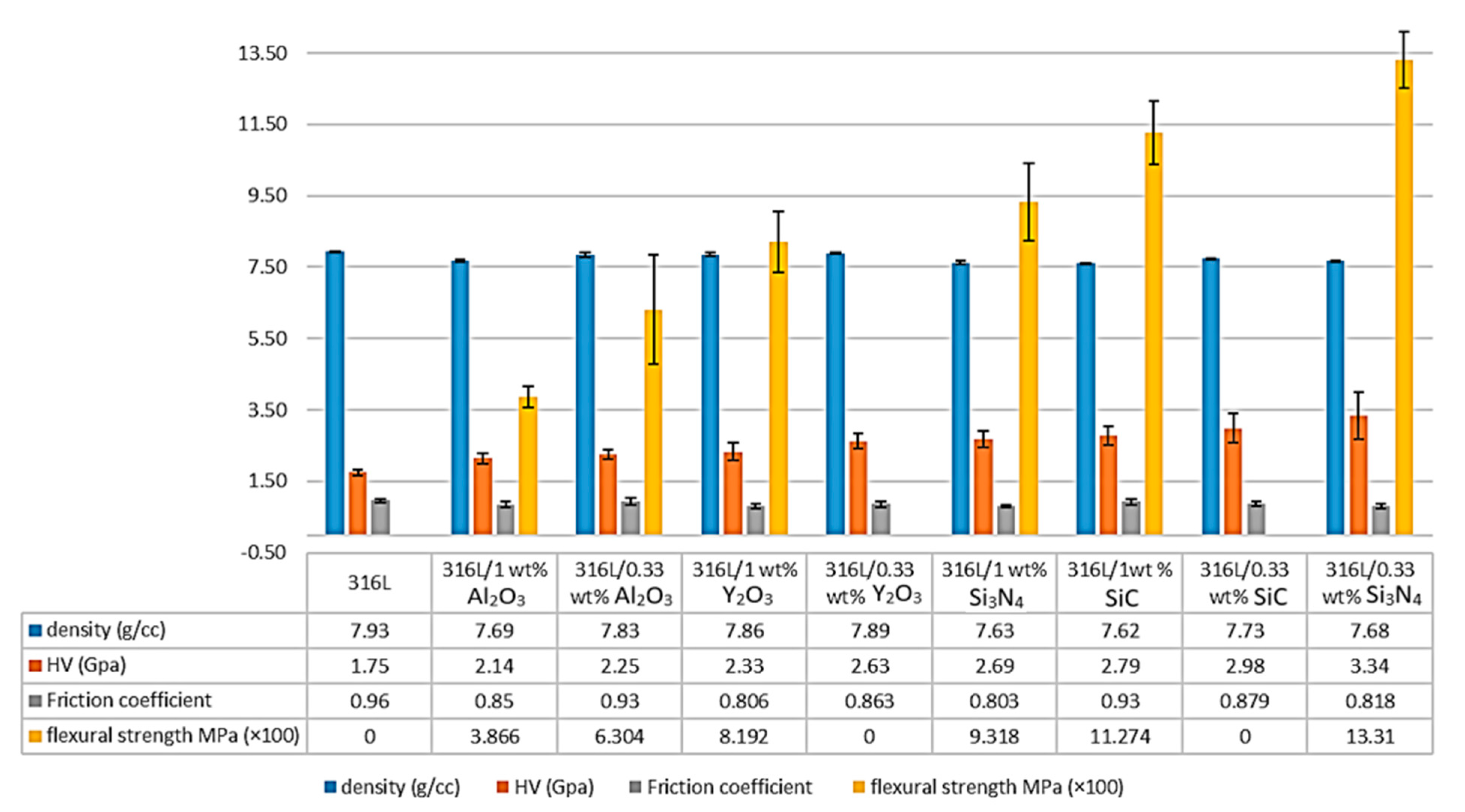
A significant increase in the composites’ microhardness was observed. It increased by 28.57% in the 316L/0.33 wt% Al2O3 and increased by 22.28% in the 1 wt% Al2O3 composite compared with the 316L reference alloy (Figure 9). This increase in the microhardness values was related to the addition of the harder nanosized alumina particles and to the presence of hardened particles as a result of the severe plastic deformation during the attrition milling process. Both the 316L/Al2O3 composites showed lower microhardness results compared with the other composites prepared by the same process [15,16,42,43] (Figure 9).

Figure 9.
Comparison of the density, microhardness, friction coefficient and the flexural strength of the 316/Al2O3 composites with other alloys prepared by the same process [15,16,42,43].
The lower microhardness values of the 1 wt% Al2O3 composite compared with the 0.33 wt% Al2O3 were a result of the nonuniform distribution of the alumina layer in the 316L/1 wt% Al2O3 composite. However, both composites showed much higher values compared with all the alumina-forming austenitic stainless steels studied by Zhang et al., where 200 HV was reported for the studied composites [44].
The flexural strength of the reference 316L, the 316L/0.33 wt% Al2O3 and the 316L/1 wt% Al2O3 samples were investigated by the three-point bending test (Figure 9). The reference 316L, the 316L/0.33 wt% Y2O3 and the 316L/0.3 wt% SiC showed high ductility and it was not possible to break the samples (data not presented in this work).
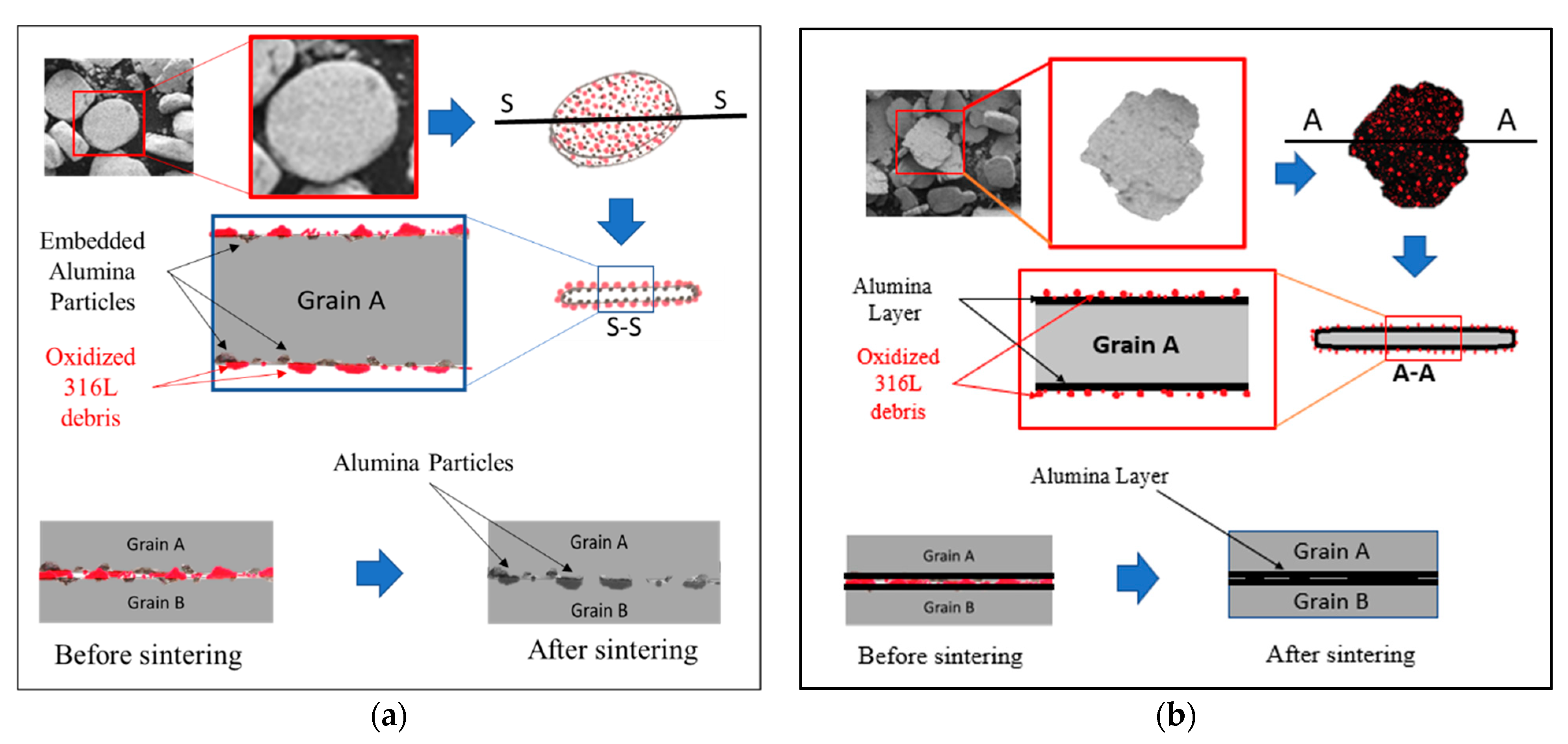
The 316L/1 wt% Al2O3 composite showed lower flexural strength, with an average of 386.6 MPa compared with the 316L/0.33 wt% Al2O3 composite, with an average of 630.4 MPa and the other composites (Figure 9). This decrease in the flexural strength of the 316L/1 wt% Al2O3 was related to the formation of a thin alumina layer on the surface of the 316L grains during the sintering process, which affected the contact between the steel grains, as illustrated in Figure 10.
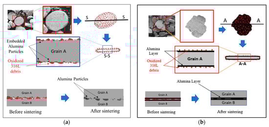
Figure 10.
Schematic representation of the sintering behaviour at the grain boundaries of the 0.33 wt% and 1 wt% alumina composites. (a) 0.33 wt% alumina; (b) 1 wt% alumina.
3.3. Effect of the Distribution of Alumina on the Contact Formation of the 316L Grains
In the case of the milled 316L/0.33 wt% Al2O3 powders, the alumina particles were homogenously distributed on the grains’ surfaces (Figure 3 and Figure 10a). During the sintering process, metallic necks started to form between the 316L grains and the 316L debris particles on the grains’ surfaces (Figure 3a and Figure 4a), which favoured the formation of 316L necks, as it is very possible for these to start melting first due to their small sizes (under 1 µm). These metallic necks developed to become metallic bridges surrounding the alumina particles and connecting the 316L grains. The alumina particles embedded in the 316L became partially embedded in the 316L grains’ boundary. Basically, the interface between two 316L grains (A and B) will be a combination of: (1) metallic bridges and (2) intermediate embedded alumina particles. It was expected that the grain boundaries would be rich with oxygen because of the presence of the oxidized 316L debris particles. Similar results were observed by elemental mapping of the grains’ interface in our previous study on the effect of adding Si3N4 on the morphological and structural properties of the 316L stainless steel for nuclear applications [16]. This oxygen richness in the interface favours the formation of chromium oxide, which will enhance the protection of the 316L grains along with the embedded alumina, as has been reported [27,28,29].
In the case of the milled 316L/1 wt% Al2O3 powders, the alumina particles were homogenously distributed and closely packed and embedded on the grains’ surfaces, forming a thin and continues alumina layer (Figure 10b). The thin alumina layer was not uniform in thickness because of the milling process and the tendency of alumina to agglomerate during wet milling. The 316L grains were connected through the intermediate embedding of the alumina thin layer that covered the steel grains’ surfaces during the sintering process (Figure 10b). Therefore, we assumed that the 316L/1 wt% Al2O3 showed lower flexural strength results compared with the 316L/0.33 wt% Al2O3 because of different contacts among the grains, considering that the bonding strength of 316L-Al2O3 was weaker than the metallic 316L-316L bond.
3.4. Tribological Properties of the Sintered Composites
The sintered 316L/0.33 wt% Al2O3 and 316L/1 wt% Al2O3 composites showed lower friction coefficient values of 0.93 and 0.85, respectively, compared with 0.96 for the reference 316L sample. This decrease in the friction coefficient was possibly related to the increase in the composite’s hardness (Figure 9). These obtained results are in agreement with the results of Kracun et al. in their study of the effect of Al2O3 nanoparticles on the tribological properties of stainless steel [45]. The addition of nanosized alumina particles increased the stainless steel’s hardness and decreased the value of the friction coefficient [45]. Figure 11 shows the related friction coefficient curves of the 316L/Al2O3 composites. The friction coefficient curve of 316L/0.33 wt% Al2O3 was somewhat more stable and uniform compared with the friction coefficient curve of 316L/1 wt% Al2O3. The nonuniformity of the latter was related to wearing of the alumina layer in the grain boundaries: the friction coefficient started low while the counterpart slid on the alumina layer. After the alumina layer wears out, the friction coefficient value increases as the 316L grains become softer. After the 316L grains wear out, another layer of alumina is exposed and the friction coefficient value decreases again. With time, the effect of the formation of the tribo-layer becomes larger, as can be observed in the last part of the friction coefficient curve of the 316L/1 wt% Al2O3 composite (Figure 11b).
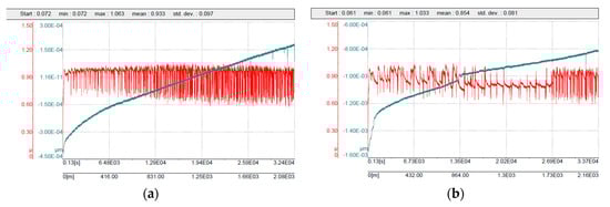
Figure 11.
Friction coefficient curves: (a) 316L/0.33 wt% Al2O3; (b) 316L/1 wt% Al2O3.
During the tribology test, the samples and the counterparts (Si3N4 balls) were damaged. An investigation of the wear track of the 316L/0.33 wt% Al2O3 (Figure 12) revealed the formation of a tribo-film (sliding layer). The high Si peak (Figure 12b) corresponding to Spot 2 was related to the formation of a sliding layer that was deposited by the eroded Si3N4 counterpart.
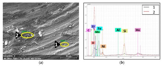
Figure 12.
EDS spectra with the associated SEM images of the tribological wear track of the 316L/0.33 wt% Al2O3. (a) SEM image of the wear track; (b) EDS spectra of the selected spots.
The investigation of the 316L/1 wt% Al2O3 composite’s wear track (Figure 13) revealed similar results to the 316L/0.33 wt% Al2O3 wear track. Spots 2 and 3 in Figure 13a are the sliding layers formed by the deposited Si3N4 counterpart’s debris. Similar results were observed in our previous study on the effect of the chemical composition on the final properties of ceramic dispersion-strengthened 316L/Y2O3 composites [42].
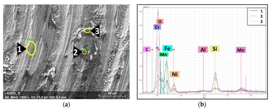
Figure 13.
EDS spectra with the associated SEM image of the tribological wear track of the 316L/1 wt% Al2O3. (a) SEM image of the wear track; (b) EDS spectra of the selected spots.
4. Conclusions
The Al2O3 dispersion-strengthened 316L stainless steel was successfully produced using attrition milling and spark plasma sintering. The intensive attrition milling produced significant morphological transformation of the globular starting powders and provided a homogeneous distribution of the nanosized alumina particles. The formation of α-Fe after milling was observed. The ferritic phase was transformed to the austenitic phase during the sintering process, as was confirmed by XRD. The following main conclusions can be drawn:
- (1)
- The addition of alumina reduced the composites’ density compared with the reference 316L alloy.
- (2)
- A thin alumina layer covering the surface of the 316L grains was detected after sintering in the case of the 316L/1 wt% Al2O3, where the EDS peak intensity of the 316L components decreased compared with the sintered reference sample, with the presence of high-intensity aluminium and oxygen peaks.
- (3)
- The addition of alumina nanosized particles and the severe plastic deformation during the intensive attrition milling induced significant morphological changes and increased the composites’ microhardness significantly.
- (4)
- The 316L/1 wt% Al2O3 composite showed lower microhardness values compared with the 316L/0.33 wt% Al2O3 because of the relatively less homogeneous distribution of the nanosized alumina particles. Nanosized Al2O3 tends to agglomerate during the milling process. However, both composites showed much higher values compared with other alumina-forming austenitic stainless steels [32,36].
- (5)
- The formation of a thin alumina layer in the grain boundaries of the 316L/1 wt% Al2O3 composite during the sintering process governed the contact formation between the steel grains, and resulted in lower flexural strength compared with the 316L/0.33 wt% Al2O3 composite, where there was no formation of an alumina layer. The 316L/0.33 wt% Al2O3 composite had higher values than the 316L/1 wt% Al2O3 composite.
- (6)
- The friction coefficient of the 316L/0.33 wt% Al2O3 and the 1 wt% Al2O3 decreased compared with the reference 316L alloy because of the increase in the composite’s hardness and the formation of a sliding layer from the eroded counterpart’s debris during the tribology test.
Author Contributions
Conceptualization, H.R.B.Z. and C.B.; methodology, K.B.; software, H.R.B.Z.; validation, K.B. and C.B.; formal analysis, H.R.B.Z.; investigation, H.R.B.Z. and Z.E.H.; resources, K.B.; data curation, H.R.B.Z.; writing—original draft preparation, H.R.B.Z.; writing—review and editing, C.B.; visualization, H.R.B.Z.; supervision, K.B. and C.B.; project administration, C.B.; funding acquisition, K.B. All authors have read and agreed to the published version of the manuscript.
Funding
This research received no external funding.
Institutional Review Board Statement
Not applicable.
Informed Consent Statement
Not applicable.
Data Availability Statement
Not applicable.
Acknowledgments
Haroune Rachid Ben Zine would like to thank the Young Researchers funding for their support and Filiz Cinar Sahin for sintering the composites.
Conflicts of Interest
The authors declare that they have no known competing financial interest or personal relationships that could have appeared to influence the work reported in this article.
References
- Yun, D.; Lu, C.; Zhou, Z.; Wu, Y.; Liu, W.; Guo, S.; Shi, T.; Stubbins, J.F. Current state and prospect on the development of advanced nuclear fuel system materials: A review. Mater. Rep. Energy 2021, 1, 100007. [Google Scholar] [CrossRef]
- Yvon, P.; Le Flem, M.; Cabet, C.; Seran, J.L. Structural materials for next generation nuclear systems: Challenges and the path forward. Nucl. Eng. Des. 2015, 294, 161–169. [Google Scholar] [CrossRef]
- Gong, X.; Short, M.P.; Auger, T.; Charalampopoulou, E.; Lambrinou, K. Environmental degradation of structural materials in liquid lead- and lead-bismuth eutectic-cooled reactors. Prog. Mater. Sci. 2022, 126, 100920. [Google Scholar]
- Banerjee, S. Overview of Indian activities on fusion reactor materials. J. Nucl. Mater. 2014, 455, 217–224. [Google Scholar] [CrossRef]
- Boutard, J.-L.; Alamo, A.; Lindau, R.; Rieth, M. Fissile core and Tritium-Breeding Blanket: Structural materials and their requirements. Comptes Rendus Phys. 2008, 9, 287–302. [Google Scholar] [CrossRef]
- Gong, X.; Li, R.; Sun, M.; Ren, Q.; Liu, T.; Short, M.P. Opportunities for the LWR ATF materials development program to contribute to the LBE-cooled ADS materials qualification program. J. Nucl. Mater. 2016, 482, 218–228. [Google Scholar] [CrossRef]
- Viswanathan, V.; Laha, T.; Balani, K.; Agarwal, A.; Seal, S. Challenges and advances in nanocomposite processing techniques. Mater. Sci. Eng. R Rep. 2006, 54, 121–285. [Google Scholar] [CrossRef]
- Gupta, R.K.; Birbilis, N. The influence of nanocrystalline structure and processing route on corrosion of stainless steel: A review. Corros. Sci. 2014, 92, 1–15. [Google Scholar] [CrossRef]
- Suryanarayana, C.; Al-Aqeeli, N. Mechanically alloyed nanocomposites. Prog. Mater. Sci. 2013, 58, 383–502. [Google Scholar]
- Di Gabriele, F.; Amore, S.; Scaiola, C.; Arato, E.; Giuranno, D.; Novakovic, R.; Ricci, E. Corrosion behavior of 12Cr-ODS steel in molten lead. Nucl. Eng. Des. 2014, 280, 69–75. [Google Scholar] [CrossRef]
- Peng, S.; Hou, J.; Yu, L.; Lu, Z. Effects of sintering temperature and Y2O3/Ti addition on microstructure and hardness of ODS-AlCrFeNi HEAs. Intermetallics 2022, 143, 107469. [Google Scholar] [CrossRef]
- Ghayoor, M.; Lee, K.; He, Y.; Chang, C.-H.; Paul, B.K.; Pasebani, S. Selective laser melting of austenitic oxide dispersion strengthened steel: Processing, microstructural evolution and strengthening mechanisms. Mater. Sci. Eng. A 2020, 788, 139532. [Google Scholar] [CrossRef]
- Guo, X.; Fan, Y.; Gao, W.; Tang, R.; Chen, K.; Shen, Z.; Zhang, L. Corrosion resistance of candidate cladding materials for supercritical water reactor. Ann. Nucl. Energy 2019, 127, 351–363. [Google Scholar] [CrossRef]
- De Luca, A.; Kenel, C.; Pado, J.; Joglekar, S.S.; Dunand, D.C.; Leinenbach, C. Thermal stability and influence of Y2O3 dispersoids on the heat treatment response of an additively manufactured ODS NieCreAleTi g/g′ superalloy. J. Mater. Res. Technol. 2021, 15, 2883–2898. [Google Scholar] [CrossRef]
- Ben Zine, H.R.; Sahin, F.C.; Czigány, Z.; Balázsi, K.; Balázsi, C. Novel SiC dispersion strengthened austenitic steels prepared by powder technology. Arch. Metall. Mater. 2019, 64, 1519–1526. [Google Scholar]
- Ben Zine, H.R.; Sahin, F.C.; Horváth, Z.E.; Czigány, Z.; Horváth, E.Z.; Balázsi, K.; Balázsi, C. Effect of Si3N4 Addition on the Morphological and Structural Properties of the 316L Stainless Steel for Nuclear Applications. Resolut. Discov. 2017, 2, 23–30. [Google Scholar] [CrossRef]
- Sakamoto, K.; Miura, Y.; Ukai, S.; Oono, N.H.; Kimura, A.; Yamaji, A.; Kusagaya, K.; Takano, S.; Kondo, T.; Ikegawa, T.; et al. Development of accident tolerant FeCrAl-ODS fuel cladding for BWRs in Japan. J. Nucl. Mater. 2021, 557, 153276. [Google Scholar] [CrossRef]
- Trtica, M.; Stasic, J.; Limpouch, J.; Gavrilov, P.; Chen, X.; Ciganovic, J. Surface behavior of 16Cr3Al ODS steel—Effects of high laser intensity 1014 W/cm2 in ambiences of air, helium and vacuum. Fusion Eng. Des. 2020, 150, 111360. [Google Scholar] [CrossRef]
- Weisenburger, A.; Müller, G.; Heinzel, A.; Jianu, A.; Muscher, H.; Kieser, M. Corrosion, Al containing corrosion barriers and mechanical properties of steels foreseen as structural materials in liquid lead alloy cooled nuclear systems. Nucl. Eng. Des. 2011, 241, 1329–1334. [Google Scholar] [CrossRef]
- Deevi, S.C. Advanced intermetallic iron aluminide coatings for high temperature applications. Prog. Mater. Sci. 2020, 118, 100769. [Google Scholar] [CrossRef]
- Huang, X.; Guzonas, D. Characterization of Ni–20Cr–5Al model alloy in supercritical water. J. Nucl. Mater. 2014, 445, 298–307. [Google Scholar] [CrossRef]
- Rivai, A.K.; Takahashi, M. Corrosion characteristics of materials in Pb–Bi under transient temperature conditions. J. Nucl. Mater. 2010, 398, 139–145. [Google Scholar] [CrossRef]
- Jun, J. Degradation behaviour of Al–Fe coatings in wet-seal area of molten carbonate fuel cells. J. Power Sources 2002, 112, 153–161. [Google Scholar] [CrossRef]
- Pawel, S.J.; Unocic, K.A. Unocic, Compatibility of an FeCrAl alloy with flowing Pb-Li in a thermal convection loop. J. Nucl. Mater. 2017, 492, 41–51. [Google Scholar] [CrossRef]
- Yu, H.; Wang, H.; Kondo, S.; Okuno, Y.; Kasada, R.; Oono-Hori, N.; Ukai, S. Radiation tolerance of alumina scale formed on FeCrAl ODS ferritic alloy. Nucl. Mater. Energy 2021, 29, 101102. [Google Scholar] [CrossRef]
- Lim, J.; Hwang, I.S.; Kim, J.H. Design of alumina forming FeCrAl steels for lead or lead–bismuth cooled fast reactors. J. Nucl. Mater. 2013, 441, 650–660. [Google Scholar] [CrossRef]
- Ritherdon, J.; Jones, A.R.; Wright, I.G. Oxidation of mechanically alloyed powders. Powder Met. 2003, 46, 319–323. [Google Scholar] [CrossRef]
- Wolski, K.; Thévenot, F.; Le Coze, J. Effect of nanometric oxide dispersion on creep resistance of ODS-FeAl prepared by mechanical alloying. Intermetallics 1996, 4, 299–307. [Google Scholar] [CrossRef]
- Ren, J.; Yu, L.; Liu, C.; Ma, Z.; Li, H.; Wang, Z.; Liu, Y.; Wang, H. Effects of Al addition on high temperature oxidation behavior of 16Cr ODS steel. Corros. Sci. 2021, 195, 110008. [Google Scholar] [CrossRef]
- Majumdar, S.; Paul, B.; Chakraborty, P.; Kishor, J.; Kain, V.; Dey, G.K. Formation of Al2O3/FeAl coatings on a 9Cr-1Mo steel, and corrosion evaluation in flowing Pb-17Li loop. J. Nucl. Mater. 2017, 486, 60e65. [Google Scholar] [CrossRef]
- Wang, J.; Long, D.; Yu, L.; Liu, Y.; Li, H.; Wang, Z. Influence of Al addition on the microstructure and mechanical properties of Zr-containing 9Cr-ODS steel. J. Mater. Res. Technol. 2021, 13, 1698–1708. [Google Scholar] [CrossRef]
- Ejenstam, J.; Szakálos, P. Long term corrosion resistance of alumina forming austenitic stainless steels in liquid lead. J. Nucl. Mater. 2015, 461, 164–170. [Google Scholar] [CrossRef]
- Pezzato, L.; Lorenzetti, L.; Tonelli, L.; Bragaggia, G.; Dabalà, M.; Martini, C.; Brunelli, K. Effect of SiC and borosilicate glass particles on the corrosion and tribological behaviour of AZ91D magnesium alloy after PEO process. Surf. Coat. Technol. 2021, 428, 127901. [Google Scholar] [CrossRef]
- Bahramian, A.; Raeissi, K.; Hakimizad, A. An investigation of the characteristics of Al2O3/TiO2 PEO nanocomposite coating. Appl. Surf. Sci. 2015, 351, 13–26. [Google Scholar] [CrossRef]
- Arrabal, R.; Mohedano, M.; Matykina, E.; Pardo, A.; Mingo, B.; Merino, M. Characterization and wear behaviour of PEO coatings on 6082-T6 aluminium alloy with incorporated α-Al2O3 particles. Surf. Coat. Technol. 2015, 269, 64–73. [Google Scholar] [CrossRef]
- Yukinori, Y.; Michael, B.P.; Michael, S.L.; Hongbin, B.; Philip, M.J.; Bruce, P.A. Development of Alumina-Forming Austenitic Stainless Steels. In Proceedings of the 22nd Annual Conference on Fossil Energy Materials, Pittsburgh, PA, USA, 8–10 July 2008. [Google Scholar]
- Pint, B.A.; More, K.L.; Wright, I.G. The use of two reactive elements to optimize oxidation performance of alumina-forming alloys. Mater. High Temp. 2003, 20, 375–386. [Google Scholar] [CrossRef]
- Al-Joubori, A.A.; Suryanarayana, C. Synthesis and stability of the austenite phase in mechanically alloyed Fe–Cr–Ni alloys. Mater. Lett. 2017, 187, 140–143. [Google Scholar] [CrossRef]
- Massalski, T.B.; Okamoto, H.; Subramanian, P.; Kacprzak, L.; Scott, W.W. (Eds.) Binary Alloy Phase Diagrams; American Society for Metals: Metals Park, OH, USA, 1986; Volume 1. [Google Scholar]
- Marattukalam, J.J.; Karlsson, D.; Pacheco, V.; Beran, P.; Wiklund, U.; Jansson, U.; Hjörvarsson, B.; Sahlberg, M. The effect of laser scanning strategies on texture, mechanical properties, and site-specific grain orientation in selective laser melted 316L SS. Mater. Des. 2020, 193, 108852. [Google Scholar] [CrossRef]
- Chattopadhyay, P.; Samanta, A.; Lojkowski, W.; Fecht, H.-J.; Manna, I. Microstructure/Phase Evolution in Mechanical Alloying/Milling of Stainless Steel and Aluminium Powder Blends. Met. Mater. Trans. A 2007, 38, 2298–2307. [Google Scholar] [CrossRef]
- Ben Zine, H.R.; Balázsi, K.; Balázsi, C. The effect of the chemical composition to the end-properties of ceramic dispersed strengthened 316l/Y2O3 composites. Period. Polytech. Chem. Eng. 2019, 63, 370–377. [Google Scholar] [CrossRef]
- Balázsi, C.; Ben Zine, H.R.; Furko, M.; Czigany, Z.; Almasy, L.; Ryukhtin, V.; Murakami, H.; Göller, G.; Yucel, O.; Sahin, F.C.; et al. Microstructural and magnetic characteristics of ceramic dispersion strengthened sintered stainless steels after thermal ageing. Fusion Eng. Des. 2019, 145, 46–53. [Google Scholar] [CrossRef]
- Zhang, S.; Dong, D.; Wang, Q.; Dong, C.; Yang, R. High-Temperature Oxidation Resistance of Alumina-Forming Austenitic Stainless Steels Optimized by Refractory Metal Alloying. Metals 2021, 11, 213. [Google Scholar] [CrossRef]
- Kračun, A.; Tehovnik, F.; Kafexhiu, F.; Kosec, T.; Feizpour, D.; Podgornik, B. Effect of Al2O3 nanoparticles on the tribological properties of stainless steel. Mater. Tehnol. 2019, 53, 607–615. [Google Scholar] [CrossRef]


Disclaimer/Publisher’s Note: The statements, opinions and data contained in all publications are solely those of the individual author(s) and contributor(s) and not of MDPI and/or the editor(s). MDPI and/or the editor(s) disclaim responsibility for any injury to people or property resulting from any ideas, methods, instructions or products referred to in the content. |
© 2023 by the authors. Licensee MDPI, Basel, Switzerland. This article is an open access article distributed under the terms and conditions of the Creative Commons Attribution (CC BY) license (https://creativecommons.org/licenses/by/4.0/).