Article

Multi-Perspective Evaluations of Laser-Removal Quality of Acrylic Polyurethane Coatings on Aluminum Alloy Substrate

1
College of Materials Science and Technology, Nanjing University of Aeronautics and Astronautics, Nanjing 211100, China
2
State-Owned Machinery Factory in Wuhu, Wuhu 241007, China
*
Author to whom correspondence should be addressed.
Coatings 2023, 13(2), 359; https://doi.org/10.3390/coatings13020359
Submission received: 29 November 2022 / Revised: 24 January 2023 / Accepted: 26 January 2023 / Published: 4 February 2023
(This article belongs to the Special Issue Surface Treatment for Metals and Alloys)

Abstract

:
Evaluation systems for objects after laser removal have not been systematically established, yet they have great significance for repairing engineering coating materials. In general, this paper mainly focused on the surface quality after laser removal, which was simulated by thermal models and characterized by microscopic, residual chemical compositions, and wettability. The laser removal threshold was considered to be a key indicator to regulate removal precision. Here, the thermal model was used to explore the threshold was 15 J/cm2, and the ablation P was 308 W at 100 kHz. Besides, the surface structure was observed through simulation before experiments. It also predicted the effect of laser power and overlapping on surface roughness, and therefore provided the theoretical reference for experiments. Then, two groups of samples were set up of the surface of acrylic polyurethane coatings on 2024 aluminum alloy with and without anodizing treatment, respectively. After the coatings were removed, microscopic morphologies demonstrated a wavy undulation structure with little residue. Meanwhile, the increments of roughness were less than 0.5 μm and the surfaces were with nice wettability. Evaluating the surface quality from the above aspects is meaningful and helpful for the non-destructive cleaning of aircraft skin coatings.

1. Introduction

In aerospace, 2024 aluminum alloy is commonly used in structural materials for aircraft skin, frame and rib beam due to its high strength, corrosion resistance, and comprehensive performance. It is necessary to spray the surface coatings to protect aircraft skin. Aside from providing traditional protection and decoration functions, the coatings also have high-temperature resistance, antioxidant, wear resistance, decay resistance, and other properties [1]. Nevertheless, aircraft skin coatings are easily damaged by external forces, space radiation, and various air flow scouring, which can lead to aging, cracking, functional failure, and shedding [2]. It is essential to remove the damaged coatings thoroughly for the recycling of materials. Conventional methods have been used, including mechanical grinding, chemical solvent cleaning, high-pressure water jets, and ultrasonic cleaning technologies. Presently, the coating detergent dichloromethane, characterized by high pollution and cost, is the main component of the solvent and has been discarded [3]. High-pressure water jets and ultrasonic cleaning are environmentally friendly methods, yet inefficiency is an obvious drawback that hinders the practical application of these methods [4]. Mechanical methods can barely meet industry standards due to low efficiency, low accuracy, and potential secondary damage to the surface, leading to limited applications in coating removal [5].
Laser technology is extensively used to remove oil stains, paints, particles, and coatings for its rapid, high precision, and efficiency [6]. Laser removal is an ideal method to non-destructively remove aircraft skin coatings by using a high-energy short-wavelength pulse laser. Compared to traditional methods, laser removal technology is non-contact, non-polluting, and economical [7]. Currently, the laser can effectively remove micron polymer particles without damaging the silicon substrate. Additionally, the research on polymer film substrate structure nano/microtextured by nanosecond laser pulses was explored [8,9,10,11]. Moreover, the research on aircraft skin after laser removal mainly focuses on surface integrity including mechanical properties, surface morphology characteristics, and surface microscopic characteristics [12,13,14]. Meanwhile, the finite element method (FEM) has been used to forecast the laser process effect in studies [15,16,17]. However, when the coatings are completely removed, the surface quality needs to be evaluated from multiple perspectives to ensure patched performance. Besides, researchers suggest that laser eliminates the organic coatings based on the ablation mechanism and vibration mechanism [18]. The specific removal mechanism has to be analyzed in experiments by different inspection methods.
In this work, the laser removal threshold was obtained and the increment of surface roughness induced by laser power and the overlapping ratio was established by the thermal model. Meanwhile, the influence of alumina layer induced by anodizing treatment on complete thresholds for acrylic polyurethane coatings was investigated through other expeiments, and surface quality after laser removal process was appraised from multiple perspectives. The laser complete thresholds and surface cleanliness were surveyed by morphology observation and chemical composition analysis. Moreover, the flatness and wettability of samples after removal process were evaluated using roughness and contact angle, respectively. Furthermore, the underlying mechanism of laser removal behavior was explored to further improve the efficiency of aircraft skin reparation.

2. Materials and Methods
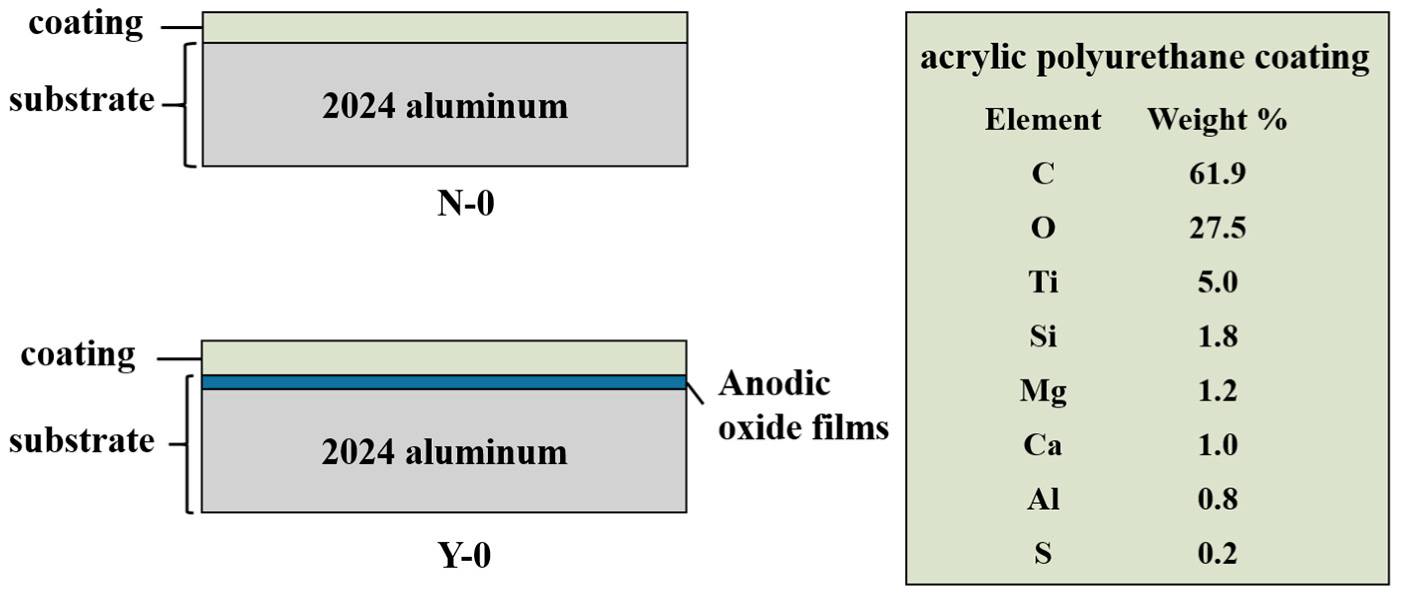
2.1. Materials

The 2024 aluminum alloy was picked as experimental material and cut into samples with sizes of 40 mm × 40 mm × 2 mm. The nominal chemical composition is shown in Table 1. Before laser removal, the samples were washed with acetone, which aimed to clean oil and grease. The anodic oxidation process was carried out on the sulfuric acid electrolyte, where the specimen was used as an anode and the stainless steel as a cathode. The thickness of the anodic coating (Al2O3) was about 5 ± 0.22 μm. A zinc yellow primer and top acrylic polyurethane coatings were sprayed on the surface of the substrates with a thickness of 70 ± 15 μm. The specimen was named Y-0 and the untreated 2024 aluminum alloy surface was sprayed with the same coatings as the control called N-0. The sectional view of the specimens and the main surface elemental components of the acrylic polyurethane coatings were characterized by EDS, as shown in Figure 1.

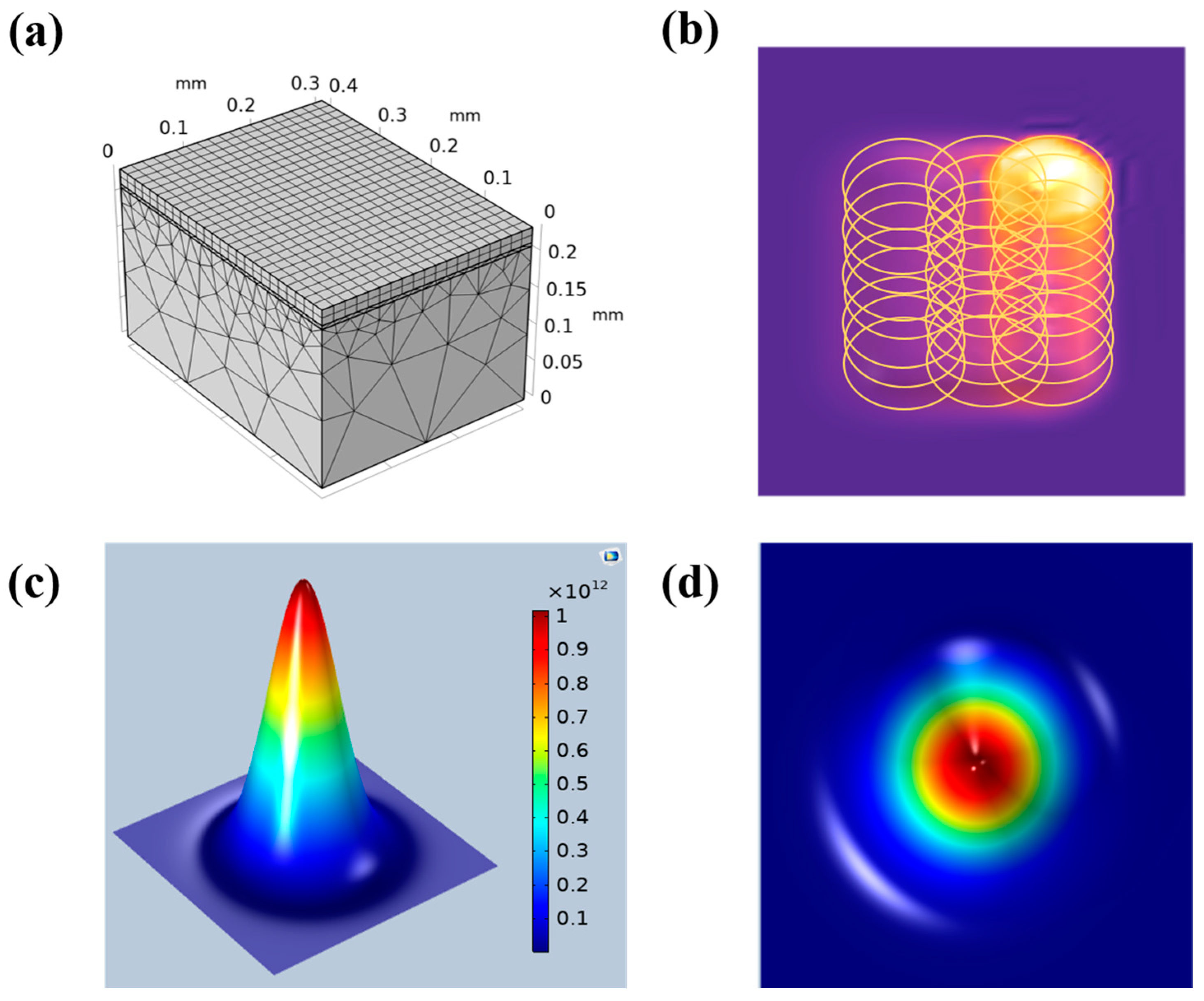
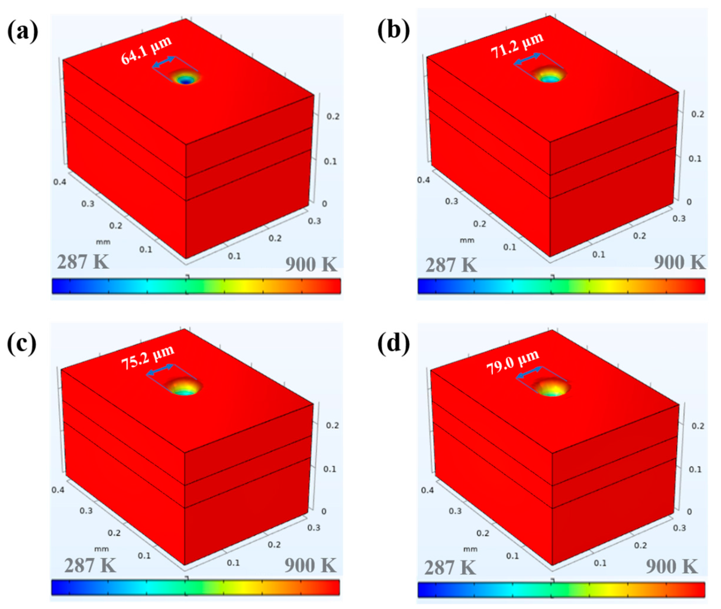
2.2. Thermal Modeling

The ablation threshold of acrylic polyurethane coatings was obtained by FEM before laser removal. COMSOL Multiphysics software has the advantage of multi-physical field coupling, covering multiple modules. Based on the FEM, the software uses equations of partial differential equations to complete the calculation and simulation.
The mechanisms for laser-removing coatings include vibration and ablation. The complicated mechanisms result in difficulty in modeling. In this work, our purpose is to effectively remove coatings, and we also consider the interaction between the laser beam and the surface layer. In the present work, the process was assumed to use ablation as the main mechanism for the laser removal process; hence, in the model, we did not consider the effect of vibration. To effectively simulate the laser removal process, four reasonable simplifications are made: (1) The materials are uniform and always isotropic; (2) Material physical parameters do not change with temperature; (3) The materials do not undergo chemical reactions or generate other substances; (4) The vibration mechanism and the absorption of energy by gasification molecules are not considered.
In this study, the geometry model was established in Figure 2a,b while the laser beam has an approximately Gaussian distribution in Equation (1), and the main view and top view are shown in Figure 2c,d [19]:
Q = PA f π p w R 2 e 2 x x t 2 + y y t 2 R 2 ,
where Q is the laser heat source, A is the absorption coefficient for 1064 nm laser, P is the laser power, f is the pulse frequency, pw is the laser duration time, and R is the radius of the laser spot.
In the laser removal process, the heat conduction between the coatings and the substrate conform to Fourier’s law, and the heat flux per unit volume is proportional to the temperature gradient, as shown in Equation (2) [20]:
Q = −k∇T,
where Q is the heat flux per unit volume, k is the heat conduction coefficient, and ∇T is the temperature gradient.
The heat transfer boundary conditions during the laser interaction with the model are shown below. The input heat qv is in the form of generalized inward heat flux in units of W/cm2 [21].
q v = Q × s t e p t ,
where s t e p t is a step function with a small transition region to increase the convergence of the model.
The model experiences certain heat exchange with the external environment: heat convection and heat radiation, of which the boundary constraints were given as Equations (4) and (5).
The heat convection of the model to the air is shown in Equation (4) [22]:
q v = h T e x t T ,
Additionally, h is the heat transfer coefficient between model and air.
The thermal radiation of the model to the surrounding environment is shown in Equation (5) [23]:
q v = ε σ T e x t 4 T 4 ,
where: ε is the surface emissivity of the material, σ is the Boltzmann constant, Text is the ambient temperature, and T is the temperature at the boundary of the model.
We add deformation geometry to COMSOL Multiphysics, and then apply deformation to all domains of the model as free deformation. After that, the initial grid conditions and displacement are set as follows:
The initial value of grid displacement is shown in Equation (6) [24]:
d X 0 = d Y 0 = d Z 0 = 0 ,
where, dX0, dY0 and dZ0 represent the displacement of the grid along the three axes, respectively.
In order to achieve laser removal of polyurethane coatings, a moving speed along the Z direction is added to the top surface of the grid as the removal speed [25], as shown in Equation (7) below [26]:
V = q v ρ × H S ,
where: ρ is the density of the coatings in unit of kg/m3, and HS is the heat of sublimation in the unit of J/(kg. K).

2.3. Laser Removal Experiments

The laser removal technique was accomplished in an ambient atmosphere using a nanosecond fiber laser (JICUI, Nanjing) with a maximum average power of 300 W, a wavelength of 1064 nm, a laser pulse width of 100 ns, and a maximum pulse rate of 1000 kHz. The diagram of laser removal technique is shown in Figure 3.The Gaussian beam passed through an isolator, homogenizer, and XY scanner. The final laser spot arrangement is shown in Figure 2. The overlapping ratio can be calculated as follows in Equation (8) [27]:
R = 1 v D × f ,
where D is the spot diameter in 50 μm, v is the scanning speed, and f is the pulse frequency. In this equation, R means the horizontal overlapping ratio. Additionally, the vertical line spacing is fixed at 0.025 mm.
Another crucial role parameter is the input laser energy, the equation of laser power density E below [28]:
E = 4 P f π D 2 ,
where P is the laser power in W, and E is the laser fluence in J/cm2. The experimental scheme is presented in Table 2 by orthogonal experiment.

2.4. Surface Quality Characterizations

The morphology characterizations and elemental analysis of the surface before and after removal were inspected with 3D microscopy (DOF, Leica, DVM8, Weztlar, Germany) and digital microscopy (SEM, EDS, TESCAN LYRA3). Fourier transform infrared spectroscopy (FTIR, Thermo Fisher Scientific, Nicolet iS20, Massachusetts, USA) was carried out to study and evaluate the chemical composition on surfaces. The infrared spectrum was embraced in a region of 600–3500 cm−1. The surface changes in the composition were calculated by X-ray photoelectron spectroscopy (XPS, Thermo Fisher Scientific, K-Alpha, Massachusetts, USA). The roughness and the wettability of the surfaces were measured to evaluate subsequent reuse by a surface roughness-measuring instrument (Mitutoyo SJ-210) and a contact angle-measuring instrument (DSA100, Kruss, Shanghai, China). The comparison of adhesive force was achieved using a commercial CSEM Revetest scratch tester. During testing, a Rockwell indenter was solid over the coated surface with a scratch speed of 3 mm min−1, a normal loading rate of 14.99 N min-1, and a scratch length of 3 mm with four scratch tests for each sample. The critical load-induced adhesion failure of the coatings was confirmed by optically observing the scratch track together with the variation in the friction force.

3. Results and Discussion

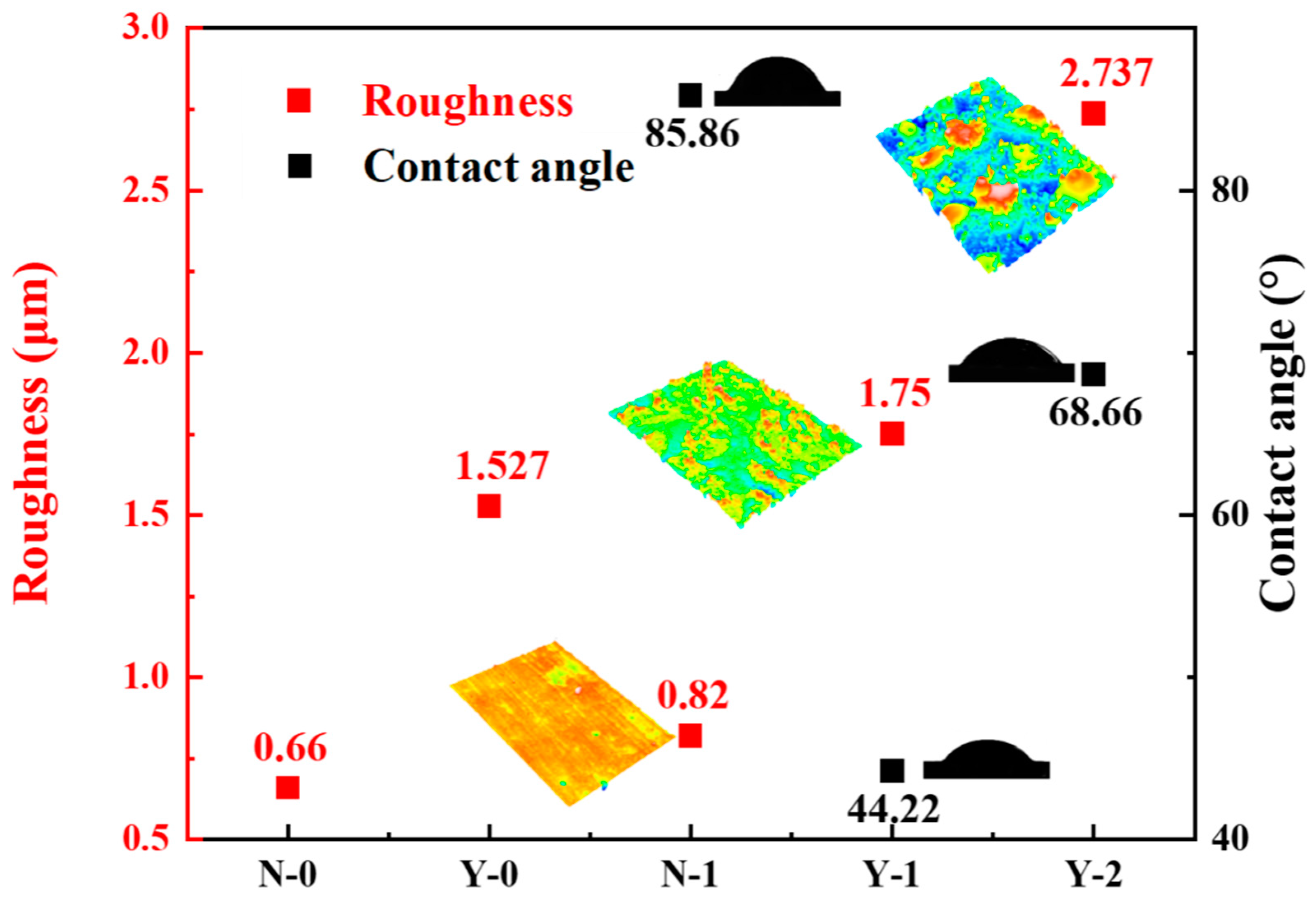
3.1. Simulation Analysis of Laser Ablation and Surface Roughness

Here, the ablation threshold of the coatings is analyzed by the square area calculation. When the scanning speed was set to 5000 mm/s at 100 kHz, the overlapping ratio was negative and a single ablative pit could be obtained. The laser beam diameter was 50 μm, the laser duration pw was 100 ns, and the relationship between laser power P and the diameter of the ablation pit DA was shown in the following Equation [29].
D A 2 = 2 r 0 2 ln P + ln 2 f π r 0 2 φ t h ,
In the study, r0 is the radius of the laser beam waist, and φth is the ablation threshold for coatings.
So, by measuring different laser power on laser ablative pit radius, we can determine the function relationship between DA2 and lnP. The ablative pit with different laser power at different laser power was shown in Figure 4. Then, the ablation threshold φth can be obtained by calculation. The slope and intercept are shown in Figure 5. The slope is 2 r 0 2 (30.3 ± 0.6) × 102, and it turns out the radius of the laser beam waist is 39 ± 3 μm. Finally, the intercept is 2 r 0 2 ln 2 f π r 0 2 φ t h (−109.9 ± 0.3) × 102, the result turns out that φth is 15 ± 3 J/cm2, and the ablation P is (3.08 ± 0.21) × 102 W at 100 kHz, which can be a valid reference for later experiments.
By simulating the laser removal treatment, the surface morphology and roughness were observed and recorded in Figure 6. Conversely, the surface roughness here is the height of the distance from the highest place to the lowest on the cross side in Rz. From the beginning, the surface was set to be smooth, so the value here represented the increment of surface roughness. With the increase in P, the circular holes owing to the Gaussian distribution of regular arrangement on the surface are deepened with a fixed form, as illustrated in Figure 6a. The circular Gaussian beams render wavy undulation, leading to regular array surfaces. Additionally, the wavy undulation structure is more obvious with the increase in laser energy. The surface roughness after laser treatment with different P and R (±0.02 mm) is shown below in Figure 6c. It demonstrates that the higher laser energy, the deeper the pit depth left by the laser beam, and so the rougher the surface. Besides, with the increase in the overlapping ratio, the surface would become rougher first and then smoother. The main reason is that, when R is less than 70%, the pits become more obvious. When it gets higher, the pits will be filled by a higher overlapped laser beam, which will finally reduce the surface roughness. For a removed surface, the increment of roughness is less than 0.5 μm, and then it is regarded as a reasonable range. So, for acrylic polyurethane coatings, when the P is less than 300 W or R is higher than 70%, the removed surface can be considered smooth.

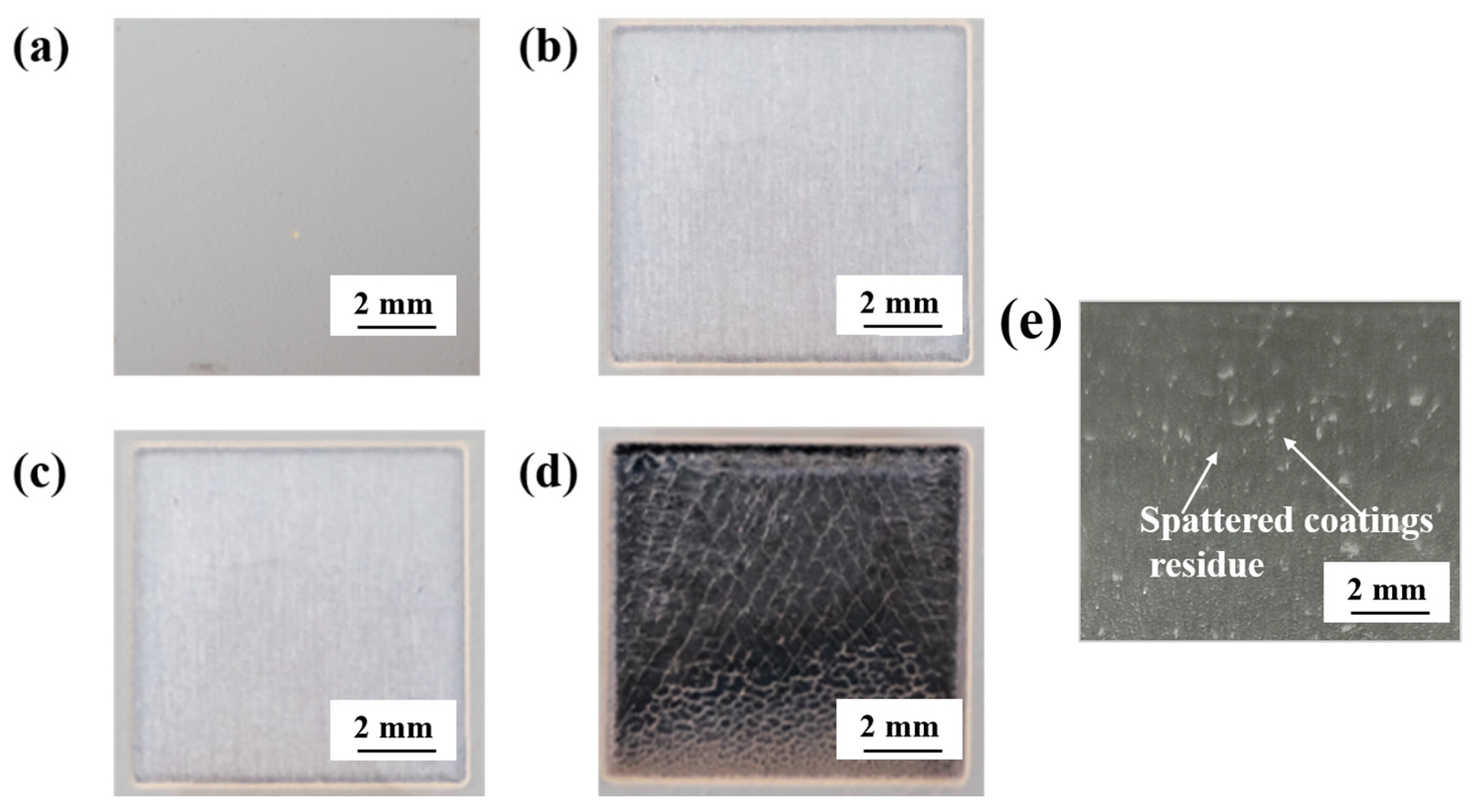
3.2. Surface Cleanliness Analysis

The surface quality is deeply bonded to laser fluence and overlapping ratio, while the appropriate laser removal process can obtain a non-destructive surface. To visually observe the surface quality, macroscopic morphology is demonstrated, as illustrated in Figure 7a–d. Before cleaning, the acrylic polyurethane coatings surface presents dark gray. The finalized complete removal thresholds were listed in Table 3. Therefore, for the acrylic polyurethane coatings under different substrates, the complete removal threshold for Y-0 sample is E at 14.5 J/cm2, and R is 87.6%; for th, N-0 sample the E is 12 J/cm2, and R is 87.4%. In this study, the samples after complete removal are called N-1 and Y-1, respectively, and the surface carbonized sample is Y-2 owing to excessive energy. The ablation threshold of coatings is a somewhat smaller than the simulation results because the force induced by thermal expansion is simplified in models. In this model, the coating with a thickness of 70 μm absorbed laser energy and were then vaporized, and the removal threshold was 15.8 J/cm2. In the actual removal process, the coating removal threshold is 14.5 J/cm2, and the error between the simulation and the experiments is less than 5%. The dominant mechanism in laser-removing coatings is the ablation mechanism. In Figure 7e, the spattered coatings residue after the laser removal process was caused by vibration. In contrast to the vaporized coatings, the presence of the speckle coatings is smaller, confirming that the ablation mechanism is largely active. As for the difference between N-1 and Y-1, it can be explained in Figure S1. Moreover, the overlap ratio R is higher in real experiments than in simulations, where surface smoothness is guaranteed. However, the carbonized surface is due to extensive R, which not only creates a rougher surface, but also destroys the surface.
The surface cleanliness for the processed specimens is evaluated through microscopic and three-dimensional optical images, as given in Figure 8. It is observed that surface element removal is relatively thorough, as z-axis microscopic images illustrated in Figure 8a,b,d,e. There is a chromatic aberration between Figure 8a and b, which is owing to newly generated Al2O3. However, this may not have a severe impact on the performance of the substrate. Additionally, the surface-specific difference can be obtained through the XPS results, as shown in Figure S2. Compared with the above two surfaces, carbonized surfaces can generate a large number of microfractures, resulting in a rough substrate, as shown in Figure 8c,f. Carbonization is mainly due to the excessively high overlapping ratio, causing an overwhelming concentration of energy. The carbonized surface is pure black for carbon deposition, as shown in Figure 8g,h. In Figure 8i, a lot of holes were formed on the surface of the regenerated layer because the residual air was unreleased. Generally, surface carbonization is caused by improper processing, which cannot achieve the purpose of repairing engineering coating materials. It is essential for a set of scientific parameters be used to avoid material failure in laser removal technology.
For further confirmation of chemical composition removal, validation was carried out with Fourier infrared experimental. FTIR experiments on acrylic polyurethane coatings have provided vibrations and spectral signatures, indicating different organic functional groups, as displayed in Figure 9, and the corresponding results are listed in Table 4. The as-received sample refers to the original acrylic polyurethane coatings. In the spectra of the as-received specimen, the broadband at 3750–3000 cm−1 is mainly assigned to the N-H stretching vibration from the NHCOO group, which disappears after laser removal. Additionally, the two peaks at 2964 cm−1 and 2875 cm−1, assigned to the C-H asymmetric stretching vibration from the alkyl chain. In specimens N-1, Y-1, and Y-2, only a small amount remained after laser removal. It has been reported that the alkyl chain was the main constituent of acrylic polyurethane [30]. The strong peaks observed at 1726 cm−1 and 1677 cm−1 are attributed to the presence of C = O stretching vibration and C = C stretching vibration, respectively. These bands have almost disappeared after laser removal. The peak at 1485 cm-1 is determined as a C = N stretching vibration. The bands at 1450–1350 cm−1 are assigned to COO-symmetric stretching, δ(CH3) scissoring, δ(CH2) scissoring, and CH2 deformation from the esters group, which almost vanished owing to the effects of laser removal [31]. The bands at 1300–1000 cm−1 are assigned to the C-O group and C-N group, with a relatively apparent group left after laser treatment [32]. The bands at 1000–650 cm−1 are assigned to C-H out-of-plane bending vibration in the FTIR spectra. The peak bands are determined to be organic functional groups in the spectral curve of the removed surface for Y-2 specimens which are similar to those in the spectral curves of the cleaned surfaces of N-1 as well as Y-1 specimens, indicating that the remaining bonds are mostly in the form of carbon chains. The effects of laser removing organic acrylic polyurethane coatings can clear the vast majority of functional groups because no prominent peaks can be identified along the approaching straight spectrum. Under reasonable parameters, laser processing can effectively remove aircraft skin coatings to a great extent.

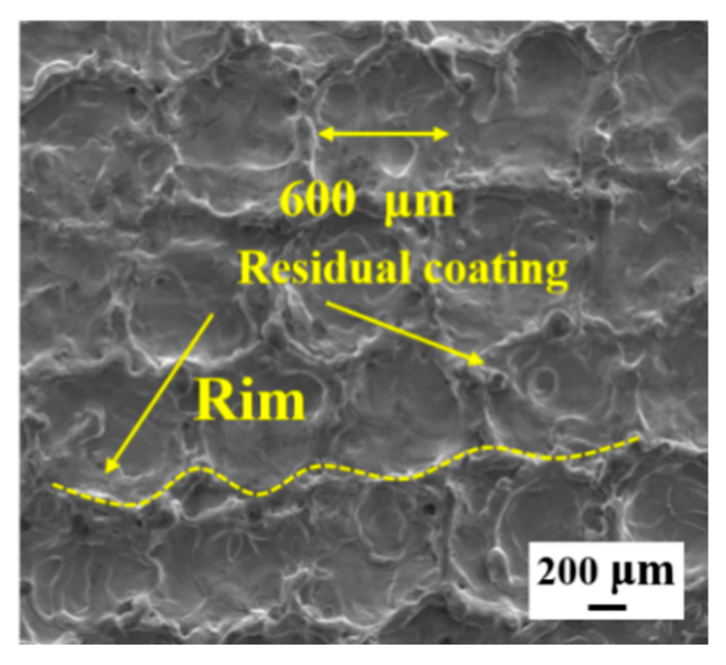
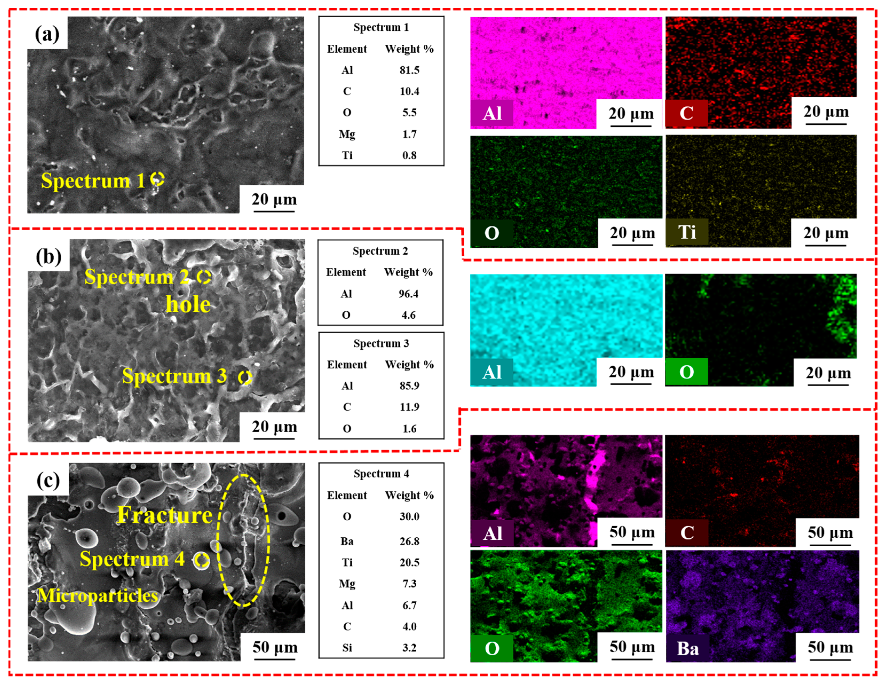
3.3. Analysis of Element Distributions and Surface Morphologies

In Figure 10, the SEM images reveal the surface morphologies of Y-1 and they equal those of the simulated model. During nanosecond laser removal treatment, high-energy and high-frequency Gaussian beams can lead to a circular spot structure, which corresponds to simulation results. It is precisely the circular surface structure that affects the roughness and wettability.
Regarding the trace residue after laser removal, this needs to be explored by microscopic element analysis. The surface observation by SEM, along with the elemental compositions of particles and mappings, indicates the residual difference after laser treatment, as displayed in Figure 11. When the laser fluence was 12 J/cm2, and the overlapping ratio was 87.4%, the surface morphologies were nearly contaminant-free, with some randomly distributed particles of some metal oxides, as depicted in Figure 11a. High frequency and fast scanning speed give the coatings the quality of being low vibration, while the dominant removal mechanism is the ablation effect [33]. The removal in this way usually leaves a portion of the residue. Spectrum 1 indicates that it occurs with residual trace primer coatings and high-melting oxides of magnesium oxide and titanium dioxide. From the mapping images, the N-1 surface presents homogeneity. Within this region, Al is the richest, followed by O, which is believed to be the result of upper coatings being cleaned and then below-aluminum alloys rapidly combining with oxygen in the air to form alumina during laser removal. The C and Ti regions are considered to constitute minor residue of the primer, as opposed to coming from substrates, because copper is the main alloying element in 2024 aluminum alloys. Figure 11b presents that a porous surface is attributed to the newly generated alumina while coatings disappear, as spectrum 2 and 3 depicted in Figure 11b. The EDS mappings of Al and O indicate a thinner alumina film layer than the N-1 specimen due to the protection of anodic oxide films. Compared to Y-1 specimen, the Y-2 specimen surface presents a fracture and plenty of large particles due to the higher scanning speed and higher frequency causing thermal expansion cracking during laser removal, as depicted in Figure 11c. For the Y-2 specimen, lower vibration between coatings and substrates is unable to separate them. Ultimately, the carbon is deposited on the surface and appears black. Furthermore, some coatings from the zinc yellow primer also remelt above the carbon, as spectrum 4 revealed. In addition to the oxygen content, the oxygen in the air is also marginally collected. As O and Al mappings illustrate, there is a thin layer of alumina at the crack, where oxygen is not as rich as at the surface. Nevertheless, C elements are decreased due to surface carbon deposition and the evaporation of carbon dioxide. Therefore, reasonable parameter settings can adjust the dominant removal mechanism of the laser removal to obtain a high-quality surface.

3.4. Effect of Anodic Oxide Films on Surface Quality

The influence of wavy undulation structures on roughness and wettability is compared by the change of surface roughness and water contact angle, as presented in Figure 12. The original roughnesses of the as-received N-0 specimen and Y-0 specimen were 0.660 μm and 1.527 μm, respectively (Ra). Due to the dense and porous aluminum oxide on the anodized substrate, the surface roughness of Y-0 specimen is more than twice that of the N-0 specimen. After laser removal, the roughness of N-1 specimen and Y-1 specimen is 0.820 μm and 1.750 μm, with increment values below 0.5 μm. The roughness increase is considered normative and feasible at less than 0.5 μm for N-1 and Y-1 specimens, which ensures surface flatness. However, the difference in roughness between the two is significantly narrower than that observed before laser processing. The roughness increase in Y-1 specimen surface is 9.64% smaller than that of the N-1 specimen. Compared to completely cleaned surfaces, the Y-2 carbonized surface is extremely coarse (2.737 μm) owing to the remelted particles and fractures. Specifically, the resulting oxides and carbides, combined with microcracks, are not evenly distributed, as shown in Figure 11c. In general, while the acrylic polyurethane coatings are removed, it is important to guarantee surface smoothness. Not only the roughness but also the wettability of the substrate surface are important indices to consider for surface quality [34]. The contact angles of N-1, Y-1, and Y-2 specimens correspond to 85.86°, 44.22°, and 68.66°, indicating good wettability after laser removal technology had been applied. The circular array structure is beneficial in reducing the contact angle for alumina with high surface energy. For Y-1 sample, the surface wavy undulation is regularly arrayed and deepened by high-energy pulses, an effect which becomes more pronounced due to the slow motion of the laser beam. While the contact angle of the Y-1 sample, in this structure it reduces by 48% compared to that of N-1 specimen. Therefore, compared with the untreated substrate, the anodized treatment substrate has a smaller surface roughness change and contact angle after coating removal, being flat and having excellent hydrophilicity. For different spraying methods, the roughness requirements have a certain range in order to ensure a good combination between coating and substrate. The surface after laser removal is under 2 μm, which is conducive to the subsequent respraying process. As occurs for surface wettability, the smaller the contact angle is, the better the wettability will be, a relationship which is conducive to the spread and extension of the coatings.
As for the remainder of functional groups, they can be explained in supplemental Figure S2. The disconnection energy E e of functional groups is mainly related to the energy of photoelectrons. According to Equation (11) [35]:
E e = n × c λ ,
where h means Planck constant 6.62 × 10⁻³⁴ J·s, c is the light speed 3 × 10⁸ m/s, and λ is the wavelength of 1064 nm in this experiment. The energy of a single photon is 1.24 eV, which is far less than 3.71 eV. However, multi-photon energy absorption leads to bond breaking and produces a large number of atoms, which are ionized by photons and continue to produce ions. The composite transfer of electrons and ions makes ultimate energy exceed 3.71 eV, a process also known as the multi-photon effect [36]. Thus, acrylic polyurethane molecules are in a state of dissociation as C-O chemical bonds are broken. The macroscopic performance of the disturbance of coating molecules is vaporizing as heating, and the functional groups with low-energy chemical bonds disappear.
The difference between O1s is related to the performance of the substrates. The reason for this was that, when the laser interacts with the coatings, some of the light is transmitted to the substrate. For a laser of 1064 nm wavelength, the absorption rate of alumina is 0.45 which is higher than that of aluminum at 0.15. Additionally, the removed threshold of alumina is 1.7 J/cm2, which is lower than that of acrylic polyurethane coatings [37,38,39]. Moreover, the specific heat of Al2O3 is low, so most of the photon energy transmitted to the underlying mechanism is absorbed by the substrate. The upward transmission of heat would thus be low, which would weaken the process of laser ablation. Eventually, the complete removal threshold of acrylic polyurethane coatings is higher on the anodized substrate. Although the energy of the photons is absorbed by Al2O3, the surface cleanliness of Y-1 is higher than that of N-1. On the whole, the presence of an alumina layer increases the removed threshold of the acrylic polyurethane coatings but protects the substrates.

4. Conclusions

The complete threshold, which is directly related to the substrate, can be divided into laser energy fluence and overlapping ratio. The simulation results have shown that the ablation threshold for acrylic polyurethane coatings was 15 J cm−2 at 100 kHz. The surface roughness would increase with higher laser power, and first, rise and then fall with an overlapping ratio going up. While the complete removal threshold coatings on substrates with and without anodized treatment were 14.5 J/cm2, 87.6%, and 12 J/cm2, 87.4%, respectively. The morphology of the laser removal surface ordered the wavy undulation structure from the Gaussian beam, resulting in a slight increase in the surface roughness. For the anodized treatment specimen, surface roughness increased from 1.527 μm to 1.750 μm, and for the specimen without treatment, it increased from 0.660 μm to 0.820 μm. Meanwhile, laser removal surfaces had fine wettability properties, while the contact angle of the anodized specimen was 48% less than that of the untreated specimen.
In the laser removal process, the accumulation of a large number of photons made the acrylic polyurethane molecules enter the dissociation state, which led to coating ablation. Meanwhile, the shockwave pressure and recoil thermal pressure created a vibrating separation between coatings and substrate. The alumina film, induced by anodizing treatment insulated the thermal and then diminished the ablation, making the vibration dominant. Ultimately, the surface after laser removal had less residue, and the newly formed alumina film was thinner than the untreated specimen, indicating the original alumina protection effect of substrates. This provides theoretical support and reference for the application of laser removal technology in the recycling of materials.

Supplementary Materials

The following supporting information can be downloaded at: https://www.mdpi.com/article/10.3390/coatings13020359/s1, Figure S1: Micro-scratch test of acrylic polyurethane coatings on different substrates: (a) 2024 aluminum alloy substrate, (b) anodized treated 2024 aluminum alloy substrate.; Table S1: The binding energy of the molecule bond.; Figure S2: High-resolution spectra C1s of specimens: (a) as received, (c) N-1, (e) Y-1, (g)Y-2 and O1s of specimens: (b) as received, (d) N-1, (f) Y-1, (h)Y-2.

Author Contributions

Conceptualization, X.H.; Methodology, J.T. and S.S.; Software, Z.H.; Validation, Z.S.; Writing—review & editing, Y.S. and W.X. All authors have read and agreed to the published version of the manuscript.

Funding

The authors acknowledge financial support from the National Natural Science Foundation of China (No. 52075246, U1937206), Natural Science Foundation of Jiangsu Province (No. BK20211568), Open Fund of Key Laboratory of Icing and Anti/De-icing (IADL20200107 and IADL20200407), Basic Research Project of Suzhou (SJC2022032), Shenyang Key laboratory of Aircraft Icing and Ice Protection (XFX20220301), Project Funded by the Priority Academic Program Development of Jiangsu Higher Education Institutions.

Institutional Review Board Statement

Not applicable.

Informed Consent Statement

Not applicable.

Data Availability Statement

Not applicable.

Conflicts of Interest

The authors declare no conflict of interest.

References

  1. Zhang, G.; Hua, X.; Huang, Y.; Zhang, Y.; Li, F.; Shen, C.; Cheng, J. Investigation on mechanism of oxide removal and plasma behavior during laser cleaning on aluminum alloy. Appl. Surf. Sci. 2020, 506, 144666. [Google Scholar] [CrossRef]
  2. Zhang, F.; Liu, H.; Suebka, C.; Liu, Y.; Liu, Z.; Guo, W.; Cheng, Y.; Zhang, S.; Li, L. Corrosion behaviour of laser-cleaned AA7024 aluminium alloy. Appl. Surf. Sci. 2018, 435, 452–461. [Google Scholar] [CrossRef]
  3. Chen, J.; Li, G.; Lin, H.; Liu, F. Covalent triazine framework nanoribbons via polar solvent-induced fragmentation for ultrafast and solar-cleaning membrane separation. Chem. Eng. J. 2022, 429, 132401. [Google Scholar] [CrossRef]
  4. Su, B.; Yao, X.; Gan, N.; Wang, P.; Cui, X. An experimental measurement research on impact load of high speed water jet acting on a rigid target by a Hopkinson pressure bar. Ocean Eng. 2022, 254, 111397. [Google Scholar] [CrossRef]
  5. Luo, H.; Wang, Z. A new ultrasonic cleaning model for predicting the flux recovery of the UF membrane fouled with humic acid. J. Environ. Chem. Eng. 2022, 10, 107156. [Google Scholar] [CrossRef]
  6. Song, H.; Wu, B. Physics-based modeling and micro-burr removal mechanism analysis for laser-induced plasma deburring. J. Manuf. Process. 2022, 75, 1217–1229. [Google Scholar] [CrossRef]
  7. Singh, P.K.; Li, F.-Y.; Huang, C.-K.; Moreau, A.; Hollinger, R.; Junghans, A.; Favalli, A.; Calvi, C.; Wang, S.; Wang, Y.; et al. Vacuum laser acceleration of super-ponderomotive electrons using relativistic transparency injection. Nat. Commun. 2022, 13, 54. [Google Scholar] [CrossRef]
  8. Kudryashov, S.I.; Allen, S.D. Removal versus ablation in KrF dry laser cleaning of polystyrene particles from silicon. J. Appl. Phys. 2002, 92, 5159. [Google Scholar] [CrossRef]
  9. Kudryashov, S.I.; Allen, S.D.; Shukla, S.D. Experimental and theoretical studies of laser cleaning mechanisms for submicrometer particulates on Si Surfaces. Part. Sci. Technol. 2006, 24, 281–299. [Google Scholar] [CrossRef]
  10. Krylach, I.V.; Kudryashov, S.I.; Fokina, M.I.; Sitnikova, V.E.; Olekhnovich, R.O.; Moskvin, M.K.; Shchedrina, N.N.; Gonchukov, S.A.; Odintsova, G.V.; Uspenskaya, M.V. Directional autonomous water flow in laser-engineered microfluidic gradient structures on polymethylmetacrylate-coated steel surface. Laser Phys. Lett. 2020, 17, 085602. [Google Scholar] [CrossRef]
  11. Krylach, I.V.; Fokina, M.I.; Kudryashov, S.I.; Veniaminov, A.V.; Olekhnovich, R.O.; Sitnikova, V.E.; Moskvin, M.K.; Borodina, L.N.; Shchedrina, N.N.; Shelygina, S.N.; et al. Microfluidic water flow on laser-patterned MicroCoat®–Coated steel surface. Appl. Surf. Sci. 2022, 581, 152258. [Google Scholar] [CrossRef]
  12. Guo, Z.; Hu, K.; Cao, T.; Liu, S.; Yan, J.; Li, Z.; Xu, Q.; Corkum, P.B.; Peng, J. Energy deposition and incubation effects of nonlinear absorption of ultrashort laser pulses in dielectrics. Opt. Express 2022, 30, 10317. [Google Scholar] [CrossRef]
  13. Zhou, Y.; Gao, Y.; Wu, B.; Tao, S.; Liu, Z. Deburring Effect of Plasma Produced by Nanosecond Laser Ablation. J. Manuf. Sci. Eng. 2014, 136, 024501. [Google Scholar] [CrossRef]
  14. Dlott, D.D. Ultra-low threshold laser ablation investigated by time-resolved microscopy. Appl. Surf. Sci. 2002, 197–198, 3–10. [Google Scholar] [CrossRef]
  15. Li, Z.; Zhang, D.; Su, X.; Yang, S.; Xu, J.; Ma, R.; Shan, D.; Guo, B. Removal mechanism of surface cleaning on TA15 titanium alloy using nanosecond pulsed laser. Opt. Laser Technol. 2021, 139, 106998. [Google Scholar] [CrossRef]
  16. He, Z.; Shen, Y.; Tao, J.; Chen, H.; Zeng, X.; Huang, X.; El-Aty, A.A. Laser shock peening regulating aluminum alloy surface residual stresses for enhancing the mechanical properties: Roles of shock number and energy. Surf. Coat. Technol. 2021, 421, 127481. [Google Scholar] [CrossRef]
  17. Zhu, G.; Wang, S.; Cheng, W.; Ren, Y.; Wen, D. Corrosion and wear performance of aircraft skin after laser cleaning. Opt. Laser Technol. 2020, 132, 106475. [Google Scholar] [CrossRef]
  18. Cheng, Y.; Jin, X.; Li, S.; Zeng, L. Fresnel absorption and inverse bremsstrahlung absorption in an actual 3D keyhole during deep penetration CO2 laser welding of aluminum 6016. Opt. Laser Technol. 2012, 44, 1426–1436. [Google Scholar] [CrossRef]
  19. Farrashbandi, N.F.; Gholamzadeh, L.; Eslami-Kalantari, M.; Sharifian, M.; Sid, A. Investigation of the effect of laser pulse length on the inverse bremsstrahlung absorption in laser–fusion plasma. High Energy Density Phys. 2015, 16, 32–35. [Google Scholar] [CrossRef]
  20. Shan, T.; Yin, F.; Wang, S.; Qiao, Y.; Liu, P. Surface integrity control of laser cleaning of an aluminum alloy surface paint layer. Appl. Opt. 2020, 59, 9313–9319. [Google Scholar] [CrossRef] [PubMed]
  21. Liu, B.; Mi, G.; Wang, C. Modification of TA15 alloy surface by high-pulse-frequency laser cleaning. J. Laser Appl. 2020, 32, 032019. [Google Scholar] [CrossRef]
  22. Wang, W.; Sun, L.; Lu, Y.; Qi, L.; Wang, W.; Qiao, H. Laser induced breakdown spectroscopy online monitoring of laser cleaning quality on carbon fiber reinforced plastic. Opt. Laser Technol. 2022, 145, 107481. [Google Scholar] [CrossRef]
  23. Francia, E.D.; Lahoz, R.; Neff, D.; de Caro, T.; Angelini, E.; Grassini, S. Laser-cleaning effects induced on different types of bronze archaeological corrosion products: Chemical-physical surface characterisation. Appl. Surf. Sci. 2022, 573, 150884. [Google Scholar] [CrossRef]
  24. Xu, M.; Shi, F.; Zhou, L.; Dai, Y.; Peng, X.; Liao, W. Investigation of laser-induced damage threshold improvement mechanism during ion beam sputtering of fused silica. Opt. Express 2017, 25, 29260–29271. [Google Scholar] [CrossRef]
  25. Kearns, A.; Fischer, C.; Watkins, K.G.; Glasmacher, M.; Kheyrandish, H.; Brown, A.; Steen, W.M.; Beahan, P. Laser removal of oxides from a copper substrate using Q-switched Nd:YAG radiation at 1064 nm, 532 nm and 266 nm. Appl. Surf. Sci. 1998, 127–129, 773–780. [Google Scholar] [CrossRef]
  26. Li, R.; Yue, J.; Shao, X.; Wang, C.; Yan, F.; Hu, X. A study of thick plate ultra-narrow-gap multi-pass multi-layer laser welding technology combined with laser cleaning. Int. J. Adv. Manuf. Technol. 2015, 81, 113–127. [Google Scholar] [CrossRef]
  27. Zhang, S.; Yan, Q.; Lin, J.; Zhang, Q.; Ding, X.; Lu, Y.; Guo, L.; Kovalenko, V.S.; Fan, L.; Yao, J. Blind-zone formation in laser shockwave nano-cleaning. Opt. Express 2021, 29, 27587. [Google Scholar] [CrossRef]
  28. Shi, T.; Wang, C.; Mi, G.; Yan, F. A study of microstructure and mechanical properties of aluminum alloy using laser cleaning. J. Manuf. Process. 2019, 42, 60–66. [Google Scholar] [CrossRef]
  29. Pobelov, I.V.; Lauritzen, K.P.; Yoshida, K.; Jensen, A.; Mészáros, G.; Jacobsen, K.W.; Strange, M.; Wandlowski, T.; Solomon, G.C. Dynamic breaking of a single gold bond. Nat. Commun. 2017, 8, 15931. [Google Scholar] [CrossRef]
  30. Lu, Y.F.; Song, W.D.; Hong, M.H.; Teo, B.S.; Chong, T.C.; Low, T.S. Laser removal of particles from magnetic head sliders. J. Appl. Phys. 1996, 80, 499–504. [Google Scholar] [CrossRef]
  31. Jiang, J.; Shen, Y.; Wang, Z.; Tao, J.; Liu, W.; Chen, H.; Liu, S.; Xie, X.; Zeng, C. Anti/de-icing performance of the one-step electrodeposited superhydrophobic surfaces: Role of surface polarity regulated by hydrocarbon radical length. Chem. Eng. J. 2022, 431, 133276. [Google Scholar] [CrossRef]
  32. Harper, A.F.; Diemer, P.J.; Jurchescu, O.D. Contact patterning by laser printing for flexible electronics on paper. npj Flex. Electron. 2019, 3, 11. [Google Scholar] [CrossRef]
  33. Xu, J.; Sun, T.T.; Jiang, S.; Munroe, P.; Xie, Z.-H. Antimicrobial and biocorrosion-resistant MoO3-SiO2 nanocomposite coating prepared by double cathode glow discharge technique. Appl. Surf. Sci. 2018, 447, 500–511. [Google Scholar] [CrossRef]
  34. Liu, Y.; Liu, J.; Sun, H.; Ju, J.; Hu, X.; Wang, C.; Leng, Y. Aluminum-target-assisted femtosecond-laser-filament-induced water condensation and snow formation in a cloud chamber. Sci. Rep. 2018, 8, 18080. [Google Scholar] [CrossRef] [PubMed]
  35. Yuan, J.; Liang, L.; Lin, G.; Li, X.; Jiang, M. Experimental study on the laser-matter-plume interaction and its effects on ablation characteristics during nanosecond pulsed laser scanning ablation process. Opt. Express 2019, 27, 23204–23216. [Google Scholar] [CrossRef] [PubMed]
  36. Ashraf, M.; Shaikh, N.M.; Kandhro, G.A.; Murtaza, G.; Iqbal, J.; Iqbal, A.; Lashari, S.A. Energy penetrated and inverse bremsstrahlung absorption co-efficient in laser ablated germanium plasma. J. Mol. Struct. 2020, 1203, 127412. [Google Scholar] [CrossRef]
  37. Tian, Z.; Lei, Z.; Chen, X.; Chen, Y. Evaluation of laser cleaning for defouling of marine biofilm contamination on aluminum alloys. Appl. Surf. Sci. 2020, 499, 144060. [Google Scholar] [CrossRef]
  38. Martinez-Calderon, M.; Haase, T.A.; Novikova, N.I.; Wells, F.S.; Low, J.; Willmott, G.R.; Broderick, N.G.R.; Aguergaray, C. Turning industrial paints superhydrophobic via femtosecond laser surface hierarchical structuring. Prog. Org. Coat. 2022, 163, 106625. [Google Scholar] [CrossRef]
  39. Hossain, S.; Shah, S.; Faisal, M. Ultra-high birefringent, highly nonlinear Ge20Sb15Se65 chalcogenide glass photonic crystal fiber with zero dispersion wavelength for mid-infrared applications. Optik 2020, 225, 165753. [Google Scholar] [CrossRef]
Figure 1. Sectional view of the specimens and elemental composition of superficial acrylic polyurethane coatings.
Coatings 13 00359 g001
Figure 2. (a,b) Simulation model, and (c,d) diagram for Gaussian distribution of laser beam.
Coatings 13 00359 g002
Figure 3. The two-dimension galvanometer spreads the light spot to the entire processing surface.
Coatings 13 00359 g003
Figure 4. The ablative pit with different laser power at (a) 150 W (b) 200 W (c) 250 W (d) 300W (corresponding to 5000 mm/s).
Coatings 13 00359 g004
Figure 5. The relationship between InP and D2 (corresponding to 100 kHz).
Coatings 13 00359 g005
Figure 6. The simulation morphology of (a) surface, (b) cross section; (c) the influence of laser energy and overlapping ratios on surface roughness.
Coatings 13 00359 g006
Figure 7. The macroscopic images of the samples before and after laser treatment for (a) N-0, (b) N-1, (c) Y-1, and (d) Y-2 samples; (e) the spattered coatings residue on the platform after laser removal.
Coatings 13 00359 g007
Figure 8. Surface microscopic and three-dimension optical images of the specimens after laser removal with (a,d) N-1 (12 J/cm2, 87.4%), (b,e) Y-1 (14.5 J/cm2, 87.6%) and (c,f,g) Y-2 (7 J/cm2, 96.5%), (h,i) microscopic images of regenerated Al2O3 from Y-1 specimen.
Coatings 13 00359 g008
Figure 9. FTIR spectra of original acrylic polyurethane coatings and residue on the laser removal surfaces.
Coatings 13 00359 g009
Figure 10. The microscopic structure of the surface of the Y-1 sample.
Coatings 13 00359 g010
Figure 11. Microscopic SEM images, particle elements, and mapping of the surface after laser removal at laser removal parameters of specimens: (a) N-1 (12 J/cm2, 87.4%) (b) Y-1 (14.5 J/cm2, 87.6%) and (c) Y-2 (7 J/cm2, 96.5%).
Coatings 13 00359 g011
Figure 12. The surface roughness and water contact angle of different specimens.
Coatings 13 00359 g012
Table 1. The chemical composition of 2024 aluminum alloy.
ElementCuMnMgCrSiZnAl
Weight %3.800.301.200.100.500.25Balance
Table 2. Experimental parameters of laser removal technology.
ParameterSymbolValue (N0)Value (Y0)Unit
Wavelengthλ10641064nm
Laser powerP150–300240–300W
Scanning speedv600–1000400–700mm s−1
Pulsed widthPW100100ns
frequencyf100–300100–300kHz
Laser beam spot diameter D5050μm
Table 3. Laser removal parameters of different specimens.
SpecimenP (W)V (mm s−1)f (kHz)E (J cm−2)R (%)
N-13008001271287.4
Y-130065010514.587.6
Y-2270340195796.5
Table 4. Peak assignments (cm−1) for FTIR spectra of acrylic polyurethane coatings.
Wavenumber (cm−1)Vibrational Assignment
3750–3000N-H stretching vibration
2700–3000C-H asymmetric stretching vibration
1726C = O stretching vibration
1677C = C stretching vibration
1485C = N stretching vibration
1450–1350COO-symmetric stretching, δ(CH3) scissoring, δ(CH2) scissoring, and CH2 deformation
1300–1000C-O group, C-N group
1000–650C-H out-of-plane bending vibration
Disclaimer/Publisher’s Note: The statements, opinions and data contained in all publications are solely those of the individual author(s) and contributor(s) and not of MDPI and/or the editor(s). MDPI and/or the editor(s) disclaim responsibility for any injury to people or property resulting from any ideas, methods, instructions or products referred to in the content.

