Review

A Review of Research Progress on the Fretting Fatigue Mechanism and Protection Measures of Metal Matrix Composites

1
Construction and Application Research Center, Naval Aeronautical University, Yantai 264001, China
2
School of Materials Science and Engineering, Southwest Jiaotong University, Chengdu 610031, China
3
School of Intelligent Manufacturing and Equipment, Chengdu Textile College, Chengdu 611731, China
*
Authors to whom correspondence should be addressed.
Coatings 2023, 13(2), 365; https://doi.org/10.3390/coatings13020365
Submission received: 26 November 2022 / Revised: 25 January 2023 / Accepted: 26 January 2023 / Published: 6 February 2023

Abstract

:
The performance characteristics of metal matrix composites (MMCs) and the need to study their fretting fatigue and wear during service are discussed. Four main elements of the study of fretting fatigue wear of MMCs (aluminum, copper, titanium, iron, magnesium, nickel, etc.) are discussed. These are factors influencing fretting fatigue, mechanism research, life prediction, and the development process of protection methods, respectively. Factors such as internal crack nucleation and development, loading conditions, and working environment are analyzed and discussed. The development trend of fretting fatigue research is outlined from several perspectives such as the fretting fatigue mechanism, research methods, and protection methods. In particular, the current state of research and the results achieved are highlighted, and some of the issues that remain to be studied are illustrated. The combined effects of fretting, fatigue and wear, the accuracy and applicability of fretting fatigue life prediction, the dispersion of the strengthening phase, and interface problems of MMCs themselves, etc., are all issues that need further research. The review summarizes some of the existing results and provides some reference help for subsequent developments.

1. Introduction

MMCs generally have a higher specific modulus, strength, and wear resistance than traditional alloys and show excellent performance in high-temperature environments. MMCs are widely used in transportation, the marine industry, medical facility, and aerospace, etc. MMCs together with polymer matrix composites, ceramic matrix composites, and carbon composites make up the modern composite system. MMCs are classified by the type of reinforcement, such as fiber reinforced (both continuous and short cut), whisker reinforced and particle reinforced, etc. MMCs can be classified as Al-based, Mg-based, Cu-based, Ti-based, etc., according to the metal or alloy matrix. MMCs aim to combine the metallic materials with the properties of reinforcing particles [1]. Metals or alloys are used as the composite matrix, while the reinforcement can be a combination of soft lubricants (such as graphite, etc.) and solid reinforcements (such as SiC, WC, etc.). Metal powders can also form metal matrix composites with each other [2], such as ZnO, Ti, Ag/TiO2, etc. The addition of reinforcements improves various properties of the composite such as strength, plasticity, wear resistance, corrosion resistance, and mechanical properties. The reinforcements in MMCs, depending on the type and size etc., can lead to different wear resistance [3,4].
In recent years, the use of MMCs in various equipment components has become increasingly common. MMCs are in service, for example, in ships, aerospace, and automobiles, where a variety of structures are fixed by riveted joints or bolts. These components are subject to vibration during operation and fretting fatigue will occur under the combined effect of cyclic loads and frictional forces, as the contact area at the contact interface experiences oscillatory movements of small amplitude [5]. Zhang et al. [6] indicate that during fretting, severe plastic deformation of surfaces or sub-surfaces can occur, causing surface wear. It also promotes the sprouting and expansion of cracks on surfaces and sub-surfaces, which is likely to lead to catastrophic failure. Chen [7], Han [8], and Iyer et al. [9] concluded that friction promotes the creation of cracks, which damage the material and lead to a reduction in fatigue life. Frictional wear behavior is influenced by many factors. External loads promote crack initiation and expansion. Friction affects the wear of surfaces and the generation of debris during fretting. These factors are influenced by the surface roughness, the external environment and cyclic loads [10,11,12,13]. Various surface modification techniques can modify the microstructure of MMCs and the dispersion of the reinforcing particles, thereby improving the wear resistance of MMCs. Therefore, it is important to go through a systematic review of MMCs.
So far, much work has been conducted on the fretting fatigue properties of various MMCs. MMCs can effectively enhance wear resistance by virtue of various reinforcements. Lu et al. [14] prepared carbon nanotubes (CNTs) Al matrix composites with enhanced wear resistance. Balakrishnan et al. [15] synthesized TiC/Al matrix composites with enhanced mechanical properties. Navazani [16] prepared ZrO2-reinforced Mg matrix composites with improved microhardness and tensile mechanical properties due to homogeneous dispersion and grain refinement of the reinforcing phase. Ahmadkhaniha et al. [17] fabricated Al oxide nanoparticles (Al2O3)-reinforced Al matrix composites which showed excellent wear behavior. Many researchers have reinforced various particles such as SiC [18], Al2O3 [19], TiC [15], SiO2 [20], ZrO2 [16], and CNT [14] into magnesium alloys. Different external factors can also influence the fretting fatigue conditions, such as the external environment, load, cyclic displacement, and amplitude, etc. Cai et al. [21,22,23] and Shen et al. [24] studied the influence of different angular displacement amplitudes, loads, and external conditions on fretting wear.
MMCs have a variety of superb properties such as high mechanical properties, electrical and thermal conductivity, and damage resistance which can be used in many industries such as automobiles, ships, railways, and aerospace with broad application prospects. The fretting fatigue of alloys has been very well studied. In addition, many investigations have been conducted on MMCs as well, but this is also very valid for fretting fatigue studies on MMCs. Therefore, the motivation for the work carried out in this paper is to provide a review of the progress of research into the mechanisms of fretting fatigue and protective measures for MMCs. This paper provides a reference for the subsequent research on fretting fatigue of MMCs.

2. Influencing Factors for Fretting Damage in MMCs
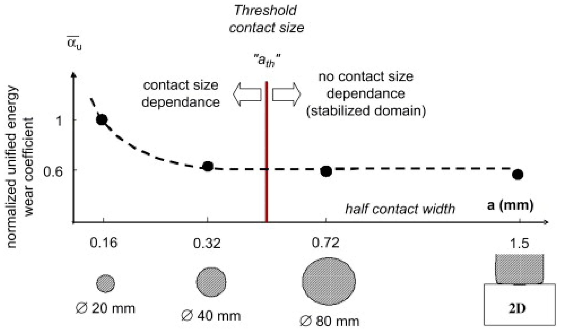
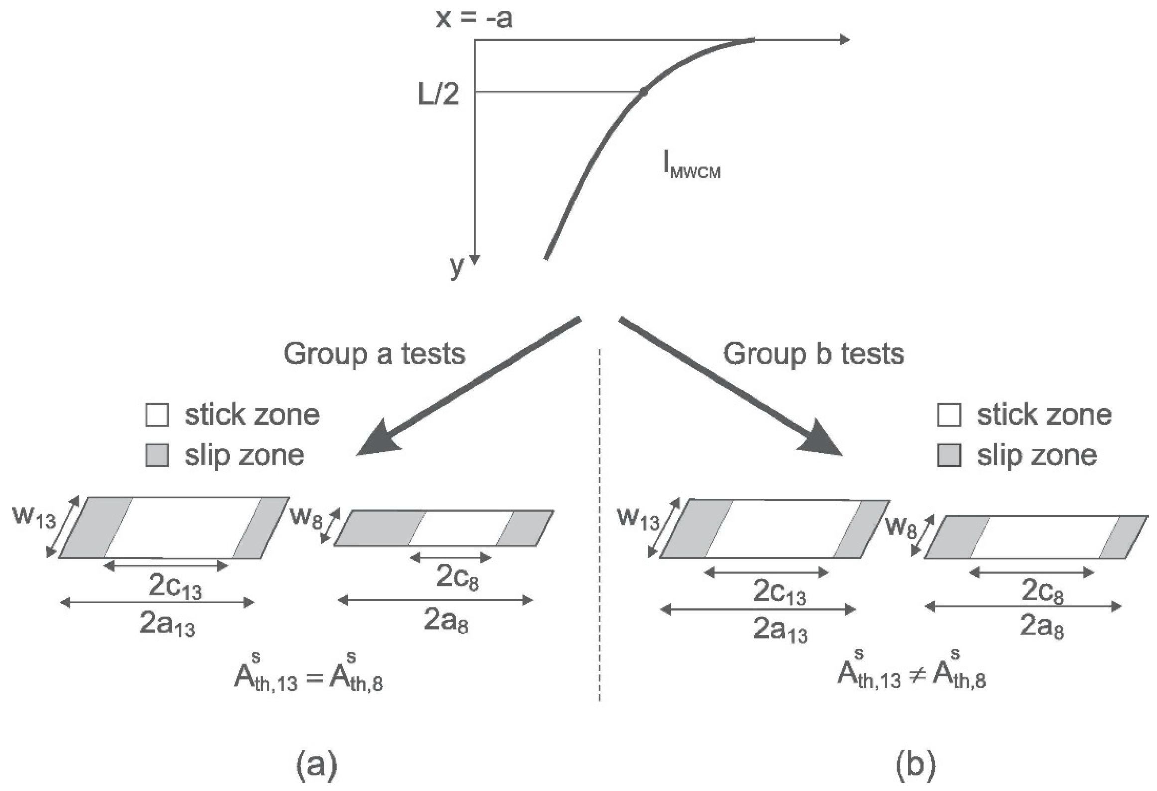
2.1. Size Effect

The same external and loading conditions lead to different fretting wear conditions due to the different contact size. The size effect is an important physical–theoretical issue. It is the change in reaction caused by an increase or decrease in spatial dimensions while geometry and all other features remain constant. The effect of contact dimensions on the fatigue life of micro-actuators is usually considered [1,25]. Differences in contact size result in different stress gradients and a consequent reduction in fretting life. The effect of the fatigue life is therefore related to the change in the stress gradient. Previous studies have shown that the wear rate decreases as the contact size increases [26,27,28] (Figure 1). S. Fouvry et al. [26] derived a unified energy wear equation. The normalized unified energy wear coefficient expressed the degree of wear and was found to be inversely proportional to the contact size. There are two explanations for the effect of wear rate with contact size on wear rate. The first is the Third Body Theory (TBT), where debris is generated during fretting friction and the amount of debris shed increases with the contact area. The increased amount of debris can reduce the wear rate of the contact surface [27,28]. Another is the concept of contact oxidation (COC) [29,30,31], where the mutual drive between the adhesive wear zone and the grinding wear zone within the fretting interface affects overall wear rate of the fretting contact. Grinding wear has a higher wear rate than adhesive wear. Therefore, the higher the proportion of grinding abrasive wear in the fretting process, the more severe the overall wear rate will be.
Cardoso et al. [32] analyzed the effect of the volume of material subjected to forces in contact and the fretting damaged area of the sliding zone on friction. Friction fatigue tests were completed with different thicknesses of specimens (Figure 2). IMWCM is a multi-axial fatigue criterion using the parameters of the modified Wohler curve method and is related to different loading conditions. L/2 is half of the critical distance in the theory of critical distances (TCD). Ath is the theoretical value from different experiments. The stress gradient effect was separated from the size effect in the experiments shown in Figure 2. The results show that the stress gradient on the subsurface has a significant effect on fatigue life, while frictional damage due to relative sliding between contact surfaces has a smaller effect on fatigue life.

2.2. High Temperature Effects

Temperature is also a very important influence on the fretting wear of the MMCs. Hager et al. [34] experimentally analyzed the frictional wear of Ti6Al4V in a high-temperature environment. The results show that temperature has a large influence on fretting friction. Rybiak et al. [35] experimentally investigated the frictional wear properties of steel in the different temperature ranges. The results show that the increase in temperature leads to a transition from mixed fretting wear to gross slip, which has a detrimental effects on fatigue life. As the temperature increases, the wear mechanism changes from adhesive wear to third-body grinding. Wang et al. [36] showed that both temperature and load factors influenced the frictional wear behavior of SAF2507 steel. The protective oxide film on the alloy is destroyed during fretting friction, thus exposing a new surface. Under local high pressure and temperature, the new surface is rapidly oxidized to produce a new oxide layer. Wear debris in the sliding contact area is gradually transformed during the friction process into a surface oxide layer with a low coefficient of friction (COF), called the “glaze” layer [37,38,39,40]. It is particularly effective in reducing damage from frictional wear and weakening the development and extension of fatigue cracks [41].
The COF decreases as the temperature increases and the wear mechanism of the MMCs changes accordingly. However, the wear rate increases due to the gradual softening of the MMCs matrix as the temperature increases. Nisar et al. [42] analyzed the high temperature frictional wear behavior of SiC-reinforced Al matrix composites. The fretting wear mechanism of MMCs changes gradually with increasing temperature. As the temperature increases, MMCs change from the mixed state to the full slip state. In addition, abrasion, debris, delamination, and oxidation, etc., will occur. Hager et al. [43] reported a similar wear surface pattern. Alloys subjected to high temperature loads at 300 ℃ and 100 N for 20 min undergo considerable softening, leading to severe plastic deformation, which leads to maximum wear.

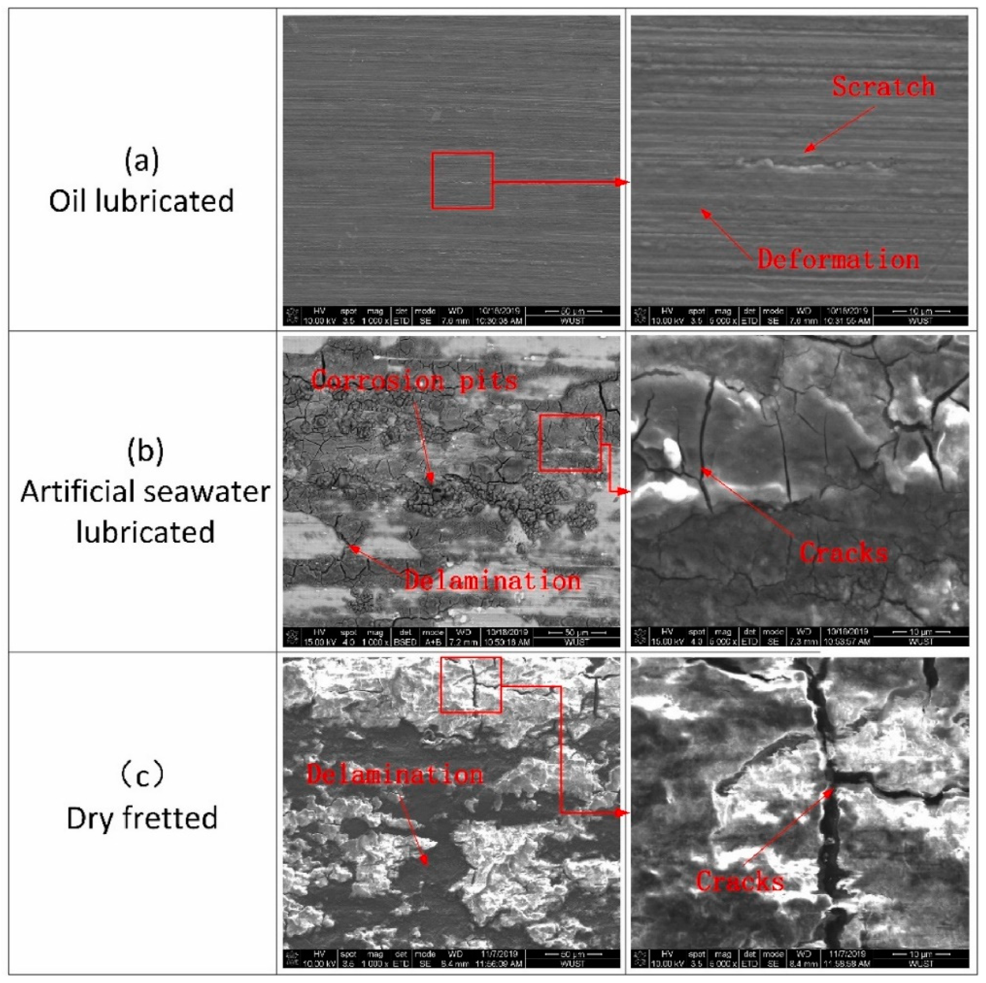
2.3. External Environment

Fretting wear is strongly dependent on the contact environment. Environmental conditions can lead to severe fretting damage behavior. MMCs are widely used in their respective environments and different external environments can have different effects on fretting wear. Through recent research on fretting, other researchers have reviewed fretting damage in several different working environments; respectively, vacuum, atmospheric, water, and oil environments.
Chen et al. [44] experimentally investigated the fretting wear behavior of Al matrix composites under the same external loading conditions in vacuum and atmospheric conditions, respectively. The COF of MMCs gradually increases as the fretting process in the atmosphere proceeds and frictional wear leads to severe surface oxidation. The oxide particles are also severely damaged due to fretting friction causing severe damage to the surface. When new wear surfaces are exposed, they are quickly oxidized and the COF increases with the wear cycle; thus, in vacuum, the COF gradually stabilizes as the fretting process proceeds. According to the energy criterion [45], wear surfaces in a vacuum dissipate more energy; thus, in vacuum, with this dissipated energy, larger plastic deformation layers tend to form. During the initial trial phase of the frictional wear cycle, the cycle is in a slip state and then becomes stick–slip. As the friction cycle increases, the surface of the composite forms an oxide layer, which prevents capillary slip on the wear surface, leading to an increase in friction and COF.
In an oil-lubricated microwear environment, external loads cause hard particles in the MMCs to be embedded within the surface, resulting in a severe ploughing effect during the fretting. The oil-lubricated surface effectively reduces shear stresses and hinders the creation and extension of cracks, making cracking and delamination virtually undetectable (Figure 3a). Thus, the dominant wear mechanism in an oil-lubricated environment is reciprocal micro-cutting wear from debris. As can be seen in Figure 3b, there are very visible cracks, corrosion pits, and delamination in the SEM image of the seawater lubricated wear surface. The strong permeability of molecules promotes crack growth [46,47]. Water molecules penetrate into microcracks and internal defects, where their growth is accelerated by shear forces. Extended cracking leads to the shedding of corrosion-generated compounds that are distributed on the wear surface as a solid lubricant [48,49], resulting in a reduction of COF but also in surface wear. Therefore, the wear mechanisms of MMCs in seawater are mainly corrosion, cracking, delamination and abrasion. In the dry fretting environment, an oxide layer exists on the surface of MMCs, which is destroyed to form a layer of oxide debris, and the wear surface is mainly characterized by cracking and delamination (Figure 3c). Due to the dry contact environment, the contact surfaces reciprocate under load during fretting and the friction process generates high heat. This promotes the creation and extension of cracks, which can lead to material delamination and wear debris. The generation of frictional heat leads to an increase in temperature in the contact zone, which promotes the oxidation process between the surface and the fragments. In addition, bulk oxidized particles are formed, which isolate the MMCs from direct surface contact and reduce the COF and acts as a solid lubricant to reduce friction. However, it can lead to a more obvious ploughing effect [50]. Therefore, the main mechanisms of wear under dry conditions are cracking, delamination, oxide, and abrasion.

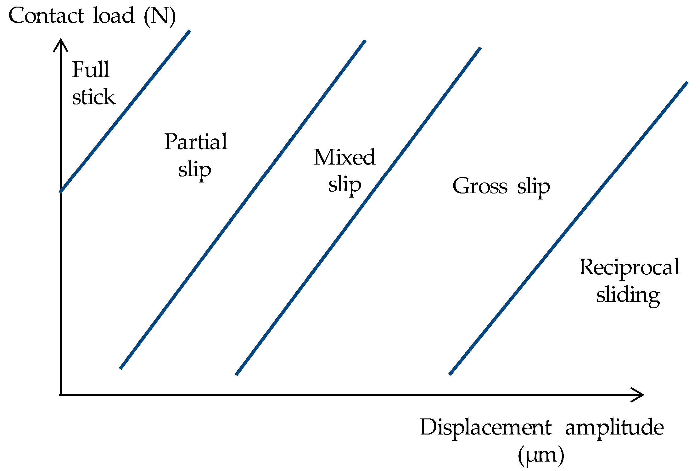
2.4. Relative Displacement Amplitude

Nishioka and Hirakawa [52,53] first found that an increase in relative sliding damaged carbon steel, leading to a reduction in fatigue life. Thereafter, Vingsbo and Soderberg [45] further experimentally verified the effect of relative slip on fatigue life. Favrow et al. [54] and Anton et al. [55] experimentally investigated the effect of relative slip on friction fatigue behaviour and found that relative slip played a major role in fretting wear. Jin and Mall [56,57] carried out similar experiments and found that relative slip affects friction fatigue life and damage mechanisms by changing the contact state.
As shown in Figure 4, the frictional wear state gradually changes from full stick to reciprocal sliding as the contact load or displacement amplitude increases [58]. Where two contact surfaces are the subject of fretting friction, if the relative slip is small, partial slip will occur and cracking will be observed mainly in the contact edge area. As cyclic loading progresses, the cracks gradually expand to increase in critical size, eventually leading to the damage of the MMCs [45,59]. A large relative slip can result in a large slip between the contact surfaces. Fretting friction wear is a case where debris and particles are generated in the MMCs during fretting. The particles produced during the wear process are partly thrown out and partly left on the contact surface, which leads to more severe wear conditions [60,61]. During fretting, the combined effect of external loads and relative slip can damage the contact surfaces. When the contact surfaces are damaged, they are more susceptible to corrosion, and this phenomenon is called friction corrosion [62].
There are several different states of contact during fretting fatigue: full stick, partial slip, mixed slip, cross slip, and reciprocal sliding. Nowell et al. [64] and Venkatesh et al. [65] stated that the reason for the variation in slip amplitude is due to the variation in tangential forces, which can effectively influence the fretting crack extension process. Lee et al. [66] also found that the increase in cyclic loading led directly to an increase in shear stress, and that there was a direct relationship between tangential forces and relative slip, which in turn led to an increase in relative slip on the contact surface. Thus, as the cyclic load applied in the fretting test increases, the fatigue life of the fretting decreases, possibly in part due to increased relative slip. In the partial slip condition, the fretting fatigue damage process is dominated by the processes of crack emergence nucleation and crack growth extension. Surface damage from fretting fatigue is mainly influenced by relative slip, while cyclic loading has relatively little effect on it. Crack extension away from the contact zone is mainly influenced by the applied cyclic load. Under total sliding conditions, wear increases rapidly with increasing sliding amplitude, making it easier to wear away microcracks and therefore increasing fatigue life again [67]. Under high cyclic fatigue conditions [68,69], relative slip plays the more important role of influence than cyclic loading. Most of the fatigue life is consumed in the vicinity of the contact zone by crack sprouting and expansion, while less fatigue life is consumed on crack expansion away from the contact zone.

2.5. Cyclic Loads and the Number of Cycles

Conditions such as the roughness of the contact zone, contact area, contact force, etc., greatly influence the frictional behavior of MMCs, which is mainly influenced by the cyclic load and the number of cycles (Figure 5). Nix and Lindley [70] stated that surface stresses generated by shear and contact loads dominated crack generation and extension. The main wear mechanisms for fretting damage are abrasion, cracking, and delamination. The COF varies with different loads as the number of fretting in microwear increases. Patel [71] showed that the degree of damage caused by friction is determined by the cyclic load and the number of cycles. In the low cycle condition, the adhesion to resist deformation increases and the reinforcing particles in the MMCs hinder crack extension. In high cyclic conditions, composites are subject to severe fretting wear damage. They are therefore susceptible to delamination and tilt cracking, which dominates the surface or sub-surface of the composite, counteracting the higher resistance of the composite to fatigue crack emergence.
It has been reported [73] that fretting generates significant localized heat in the fretting contact surface. Under low cycle loading, the heat can be dissipated sufficiently due to the small loading cycles, so that the temperature in the contact area does not rise significantly. In contrast, under high cyclic loading conditions, repeated relative sliding friction generates a large amount of heat, resulting in a significant increase in temperature. In addition, the thermal conductivity of the MMCs is generally poorer than that of the alloy [73]. As a result, the local temperature in the contact zone of MMCs is much higher than that of their alloy counterparts. Due to the massive generation of frictional heat, the lower heat dissipation capacity during fretting leads to local temperature rises of several hundred degrees in the contact zone [74]. The increase in temperature softened the MMCs matrix and weakened the reinforced particle interface energy, leading to the promotion of crack extension. In the high circumferential cycling state, cracks tend to connect through the interface with microcracks near the reinforcing particles, increasing the rate of crack expansion. As a result, MMCs have a higher fatigue strength under low cycle conditions under fretting conditions. The increase in the number of cycles results in lower fatigue life.
Compared to normal fatigue, the effect of local contact stresses leads to accelerated nucleation of microcracks, which shortens the initiation stage of fatigue cracks and leads to earlier fracture. As the amplitude of the cyclic load increases, the difference in life becomes progressively smaller. When the amplitude of the cyclic stress is sufficiently high, severe local plastic deformation occurs, which leads to stress concentrations in hard particles etc., thus promoting the emergence and expansion of microcracks. Therefore, fretting fatigue crack extension is mainly divided into micro-crack sprouting and extension caused by local contact stresses, and macro-crack extension caused by cyclic stresses [75].

3. Mechanisms of Fretting Fatigue in MMCs

3.1. Fretting Fatigue
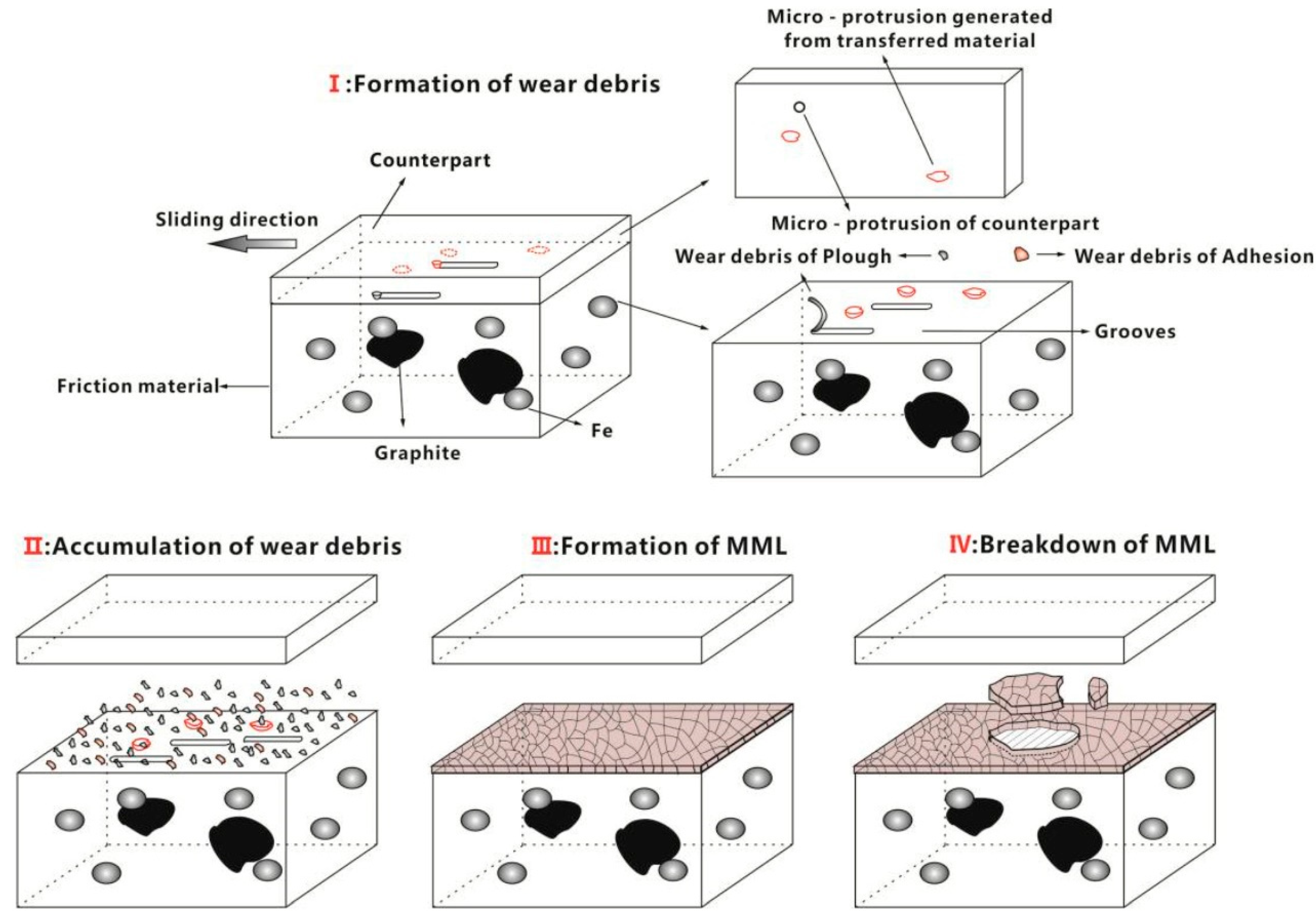
Fretting describes small oscillatory movements which occur in contact surfaces subjected to cyclic loads. Fretting fatigue occurs when repetitive loading on contacting objects causes the metal interface to slide relative to each other [76]. Fretting fatigue is the combined effect of fretting, friction, and fatigue. Fretting leads to degradation of contact surfaces or sub-surfaces and the merging of micro-cracks to form macroscopic large cracks, which greatly reduce the fatigue life of the material. Fretting fatigue usually occurs where joint components are subjected to reciprocal vibrations or relative sliding movements caused by cyclic loads. Fretting produce contact surface wear, sub-surface damage, adhesion, and local plastic deformation, which significantly reduce fretting fatigue life [67]. The contact slip zone within the partial slip zone is usually the location of crack initiation and wear on the contact surface of MMCs is usually low. Therefore, the percentage of partial slip zone affects the fretting fatigue life.
The surface alternating shear stress caused by friction generated by oscillating motion is an important factor in the formation of fretting fatigue cracks [76]. Compared to normal fatigue, fretting fatigue produces surface material loss and fatigue crack nucleation, shortening the stage of fatigue crack initiation and significantly shortening the life of the component, leading to premature material fracture [77]. Gutkin et al. [78] investigated the expansion characteristics of fatigue cracks in interference fit shafts and showed that the crack expansion was much faster under interference conditions than under plane fatigue conditions. Lee et al. [79] found that even below the micro-wear limit, many tiny fretting fatigue cracks can still occur at the contact edges. Kubota and Hirakawa et al. [60,80] observed fretting fatigue cracks in sub-surfaces due to fretting friction at contact edges.
Fretting fatigue is generally considered to be the most harmful of the different damage modes (wear from total sliding, fretting fatigue from local relative sliding and “no damage” from sticking). It leads to cracks in the edge of contact (EOC) region, where high stress gradients and local relative motion can mask microcracks until a critical length is reached [81]. Fretting fatigue allows internal tensile and shear stresses to increase, creating surface defects. Stress concentrations are created at defects and hard particles [82]. Fretting fatigue cracking begins in stress concentrated surface defects when the relative slip process throws fretting debris out of the contact zone. As the stress concentration in the fretting zone increases, micro-cracks sprout and begin to expand, eventually leading to material failure. Typically, during fretting, the contact surfaces are subjected to an externally applied cyclic load in the contact zone and the contact surfaces are displaced relative to each other, creating friction in the contact zone. The sum of normal loads, cyclic axial loads and frictional forces can create local stresses at the contact interface, thus promoting microcrack nucleation [83].

3.2. Fretting Wear

Fretting wear of MMC is complicated by the presence of reinforcements, with different reinforcing particles leading to different strengthening effects. The reinforcement may enhance the wear resistance due to its strengthening effect on the matrix. However, the reinforcement may also become part of the wear debris enhancing wear. Hard reinforcements such as ceramic particles provide a high resistance to micro-cutting of the composite material, thereby reducing the rate at which chips are cut from the composite surface during micro-abrasion. Kumar et al. [1] experimentally investigated the wear behaviour and mechanical properties of composites reinforced with SiC and MgO reinforcing particles. The results show that the wear resistance of MMCs decreases with increasing reinforcing particle content. The wear rate is lowest for the matrix alloy compared to the MMCs. Vedrtnam and Kumar [84] investigated the wear behavior of SiC reinforced Al matrix composites. The results showed that the content of the reinforcement was the most influential factor affecting the wear rate of MMCs. Factors such as applied load and relative slip were less influential. The addition of reinforcements to MMCs can limit the flow of plastic deformation [85,86].
Fretting damage usually results in surface spalling due to surface wear; spalling is caused by surface wear and sub-surface cracks, which ultimately lead to the failure of the MMCs [42]. Three fretting states were identified based on the fretting conditions, namely, partial slip mechanism, mixed stick–slip mechanism, and total slip mechanism [87]. The partial slip state is characterized by partial adhesion of the contact surfaces and severe damage to localized areas during wear, resulting in visible wear debris. The mixed stick–slip state is characterized by the coexistence of plastic deformation and flaking particles, which interact to produce debris, oxidation, and delamination, leading to more severe wear. The total sliding state is also characterized by oxidation, abrasion, and delamination wear [88,89].
Delamination is due to the extension of cracks on the surface, resulting in flake fragments [90], deep grooves, pits, and shrinkage [91]. Zhou et al. [92] observed that in MMCs, defects such as weak reinforcing particle–matrix bonding interfaces and surface oxidation resulted in cracks extending and interconnecting along the locations of these defects, ultimately leading to delamination of the surface. Adhesive wear is characterized by the formation of pits and tips due to plastic deformation caused by fretting [93]. There are usually fewer pits in adhesive wear than in delamination [91]. The presence of many grooves indicates a micro-cutting or micro-milling effect, which is described as the cause of abrasive wear [94]. Mishra et al. [95] found that grooves are shallower in abrasive wear than in delamination wear. Fretting wear is characterized by light scratches and loose debris caused by oxide chips, which are caused by cyclic stresses due to sliding between two surfaces. Tripathi et al. [96] experimentally investigated Cr matrix composites reinforced with BN, graphene, and diamond, respectively. Hard oxides appear in the BN and the diamond due to their hard grains and nailing effect. These lead to the appearance of stress concentrations, showing microcracks, micro-ploughs, and chip wear. In graphene, agglomeration occurs due to the poor dispersion of graphene [97], leading to delamination in wear.

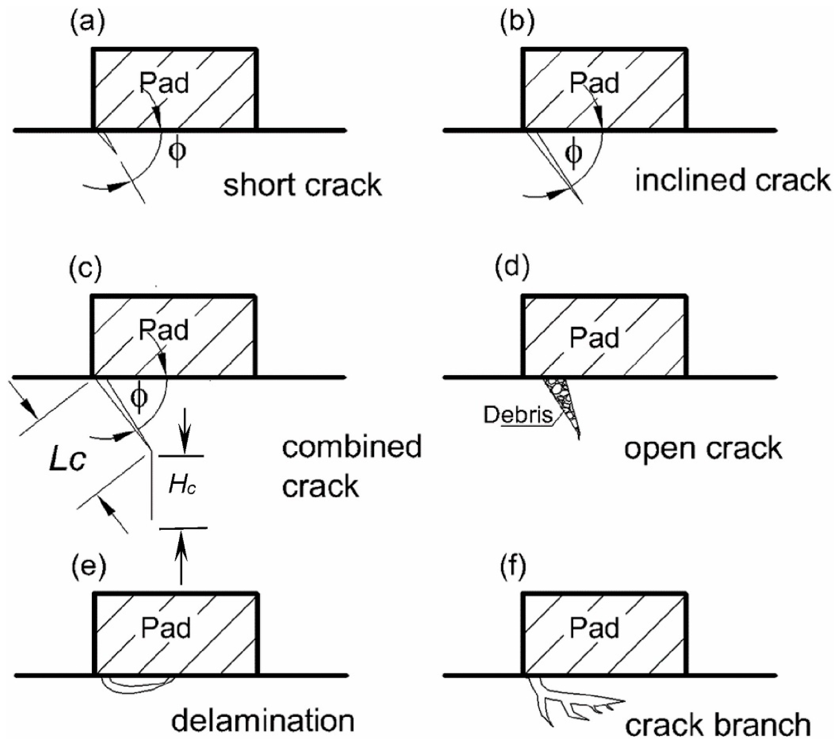
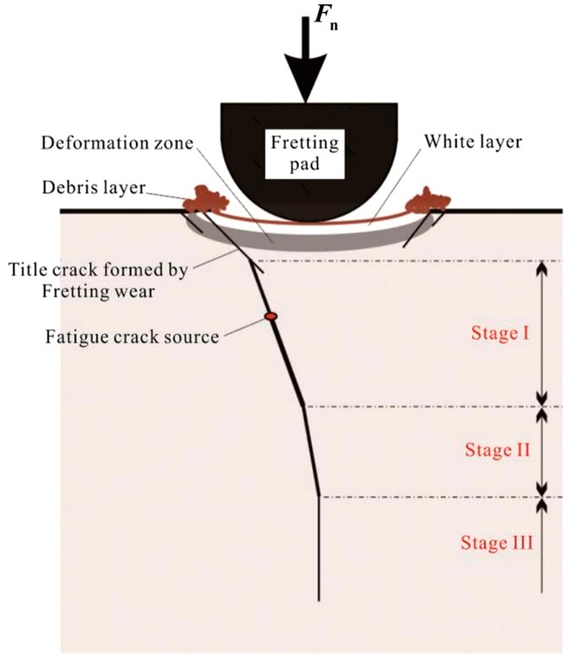
3.3. Fretting Fatigue Crack Sprouting and Extension

Under fatigue conditions, the microstructure of the MMCs usually hinders the initiation and extension of fatigue cracks [72]. The relationship between fatigue cracking and misaligned structures has been reported by many researchers [98,99,100]. In the composites, the reinforcing phase is dispersed in the microstructure. As cyclic loading proceeds, dislocations gradually increase, and dislocation cells begin to deform. The enhanced phase will act as a peg to the dislocation, causing the slip of the dislocation to be impeded. As cyclic loading continues, the density of dislocations increases considerably. Dislocations are tightly entangled with the reinforced phase and accumulate in localized areas. As cyclic loading approaches fatigue life, the number of dislocations increases dramatically, creating a high density dislocation zone around the reinforcing phase. Thus, fatigue crack nucleation sprouts locally in the area below the contact zone due to stress concentrations caused by dislocation configurations in the local damage zone. In other words, as the cycle loading period increases, the dislocations entangle and pile up with the reinforcing phases, resulting in a gradual increase in dislocation density. As the loading cycle increases, the dislocation cell deforms severely and begins to split into smaller sized dislocation cells. These changes lead to localized areas of stress concentration, resulting in the formation of free sources of cracking in the dislocation cells, producing numerous microcracks.
Typically, friction can be divided into several different states: partial slip state (PSS), mixed friction state (MFS), and slip state (SS) [23,101]. C. Q. et al. [102] found that fretting wear promotes early crack initiation and influences crack expansion under cyclic fatigue loading. Fretting fatigue cracking was categorized by finite element analysis into six categories, as shown in Figure 6.
(1)
Short cracks (Figure 6a)
Very high stress concentrations are generated around the contact area, causing tiny, short cracks to start sprouting. At this point, the stress concentrations are caused by partial adhesion of the area. Adhesive wear is therefore probably the main cause of such short cracks.
(2)
Inclined cracks (Figure 6b)
Inclined cracks are the result of the extension of the fracture mode, which is present at relatively weak locations around the contact area. Localized areas of plastic deformation and stress concentrations caused by contact zones provide the driving force for Inclined cracks.
(3)
Combined cracking (Figure 6c)
Combined cracking is the result of inclined crack propagation as the initial crack extends out of a highly stress concentrated fretting contact zone. Outside the contact affected zone, the contact load acts in conjunction with the axial load, resulting in a change of direction of crack propagation and a reoriented second segment of crack until the final fracture. Thus, the external load determines the dimensions of the first section length Lc of the crack. Higher loads lead to a premature redirection of the crack propagation and therefore Lc decreases with increasing axial load.
(4)
Open cracks (Figure 6d)
Crack openings depend on cyclic loading and debris within the crack can lead to crack opening and expansion, resulting in damage to the MMCs in the fretting and a significant reduction in fatigue life.
(5)
Delamination (Figure 6e)
Delamination consists of the merging of two short cracks. Delamination is often found during fretting in composites, where the delamination is usually parallel to the contact surface, which facilitates the formation of fragments. Delamination is caused by high shear stresses on the surface and subsurface which promote crack extension.
(6)
Branching cracks (Figure 6f)
Owing to the existence of high stress concentration zones in the reinforcing phase attachments in the composite, the inclined cracks are affected by the high stress concentration and produce some bottom sub-cracks.
Peng et al. [72] proposed a model for fretting crack extension through experiments (such as Figure 7). In the first stage, influenced by local stresses in the contact micro-zone, the main crack sprouts and combines with the tangential crack on the surface to form an initial crack at an angle to the contact surface. In the second stage, after a certain depth of crack extension, the crack extension process is influenced by the stresses within the contact surface and the direction of crack extension shifts. In the third stage, the crack is only influenced by internal stresses and the crack transitions to a direction perpendicular to the contact surface. The first and second stages of crack initiation and expansion are key to fatigue life.

4. MMCs Fretting Fatigue Life Prediction
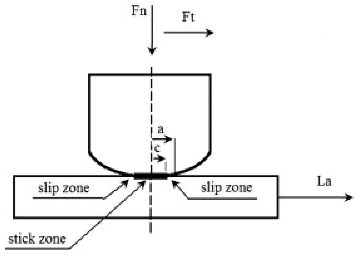
Life prediction of fretting fatigue involves the fields of tribology, fatigue and fracture mechanics, elastic-plastic mechanics, the finite element method, and metallographic science. Regarding the calculation method of fretting fatigue and life, scholars from various countries have proposed various fretting fatigue life prediction methods based on numerous experiments and studies, but all of them have certain limitations.

4.1. Ruiz Criterion

Ruiz et al. [103,104] have proposed a very effective criterion for fretting fatigue damage. As the relative slip ( s ) and shear stresses ( τ fric ) at the contact surface affect the degree of damage to the contact surface, Ruiz introduced the concept of the fatigue-fretting damage parameter (FFDP), which is defined as:
FFDP = σ tan · τ fric · s
where σ tan is the maximum tangential stress. Ziaei has made some modifications to the Ruiz criterion [105]. Firstly, a specific definition of the physics of the frictional work generated during fretting is given:
W fric * =   τ fric · ds
where s is the slip. Assuming that the load remains constant during the load cycle and a straight sliding trajectory, Equation (2) for the shaft–hub connection (SHC) simplifies to:
W fric * = 2 · s a · | τ fric |
where s a is the slip amplitude. In addition, Ziaei discovered some shortcomings of the Ruiz criterion and introduced a maximum principal stress to improve its shortcomings.
m F F D P = W fric * · σ 1
The modified fatigue fretting parameters (mFFDP) enable the prediction of shaft failure locations in polygon and shrink fit SHC finite element analysis (FEA).

4.2. Smith–Watson–Topper (SWT) Models

Smith proposed an appropriate relational equation with a range of cyclic strains and a maximum stress as a correction for the average stress of a machine load under uniaxial loading conditions [106]. The maximum fretting fatigue stress ( σ max , ff ) perpendicular to the contact surface can be defined as:
σ max , ff = σ max + 2 p 0 μ f t , max / f n , max
where σmax is the maximum machine axial stress, p 0 is the maximum Hertzian pressure, μ is the coefficient of friction under slip conditions, f n , max is the maximum normal contact load, and f t , max is the maximum tangential load.
The total strain amplitude for fretting fatigue is defined as:
ε a , F F = 1 2 v 2 v 3 E ( σ a + σ a , F t )
where v is Poisson’s ratio, E is Young’s modulus, and σ a is the machine axial stress amplitude, σ a , F t is the tangential stress amplitude.
Tangential stresses on the surface of the contact zone in Figure 8:
(1)
In the sliding belt:
σ F t , s l i p = 3 μ F n 2 π a 2 ( 1 ρ 2 a 2 ) 1 / 2                           c ρ α
(2)
Viscous zone:
σ F t , s t i c k = 3 μ F n 2 π a 2 [ ( 1 ρ 2 a 2 ) 1 / 2 c a [ ( 1 ρ 2 c 2 ) 1 / 2 ]                     0 ρ c
where ρ is the distance to the centre point of contact, a is the half-length of the contact area, and c is the half-length of the adhesive area.
Buciumeanu et al. [106] showed a good correlation between SWT parameters in predicting lifetime and experimental results. Critical plane based SWT method is a very effective physical method for crack initiation and extension in materials. The SWT method is based on the critical plane method, and it is very effective in predicting fatigue life of contact geometries.

4.3. The SWT Model Based on the Critical Plane

Shi et al. [107] proposed a fretting fatigue prediction method that takes into account cyclic strain and stress variation based on the critical plane method. The SWT parameter depends on the maximum normal stress and strain amplitude on the critical plane by
P S W T = σ m a x ε a
where σ m a x and ε a are the maximum directional stress and normal strain amplitude on the critical surface, respectively.
Formal relationship between the parameter PSWT and fatigue life:
P S W T = ( σ f ) 2 E ( 2 N f ) 2 b + σ f ε f ( 2 N f ) b + c
where σ f and b are fatigue strength coefficients and fatigue strength indices, ε f and c are fatigue ductility coefficients and fatigue ductility indices and E is the modulus of elasticity. In particular, in order to better characterize the stress gradient along the vertical sliding direction, the stress distribution along the two paths was determined, for which either the stress or strain can be expressed by [108]:
σ θ = σ x + σ y 2 + σ x σ y 2 cos 2 θ + τ x y sin 2 θ
τ θ = σ x σ y 2 sin 2 θ + τ x y cos 2 θ
ε θ = ε x + ε y 2 + ε x ε y 2 cos 2 θ + γ x y 2 sin 2 θ
γ θ = ( ε x ε y ) sin 2 θ + γ x y cos 2 θ
where θ represents the plane that is perpendicular to the contact surface. σx and σy are the partial stresses in parallel and vertical contact directions, respectively.

4.4. Fretting Fatigue Damage Criteria

Li et al. [67] also developed a friction fatigue damage criterion for planar surfaces and proposed a unified criterion for fretting fatigue in planes, with fretting-related damage parameters (FRD), expressed as follows:
FRD = α + β Q μ P
where α and β denote the influencing factors of the fretting damage parameters, α 1 , β > 0 , μ is the COF, Q is the tangential force amplitude, and P is the standard load.
As shown in Figure 9, using this fretting damage parameter, the following fretting fatigue damage criterion is established as:
FRD · D P F F = f ( N f )
Therefore, the following relationships exist:
FRD · D P F F = D P P F
Substitute Equation (1) into Equation (3):
α + β Q μ P = D P P F D P F F
where Q / μ P and D P P F / D P F F are known, and the coefficients α and β can be determined by fretting experimental data.
The fretting fatigue damage parameters are also related to the plane fatigue damage parameters. Fretting friction effects can lead to a significant reduction in fatigue life. This means that the value of Q / μ P represents the strength of the fretting fatigue under the fretting fatigue damage parameter. The critical plane method is therefore effective in predicting crack initiation and extension, and in predicting fretting fatigue life.

4.5. Multi-Axis Fatigue Model

To simulate wear, the local part of Archard’s law [109,110] or the dissipated friction energy relation [111,112] is used. Debris shedding occurs when the material is worn due to fretting damage during fretting. The material loss at the contact surface can be expressed in terms of vertical displacement as follows:
Δ h i , j = k = 1 n inc α q ( x j , t k ) Δ s ( x j , t k ) Δ N
where Δ h i , j is the wear depth at distance from the contact surface during fretting wear. α is the dissipative energy wear factor, while q ( x j , t k ) and Δ s ( x j , t k ) are the contact shear and relative sliding increments respectively.
In the process of fatigue life prediction, it is necessary to apply the incremental damage formula to the multi-axial fatigue parameters to supplement the non-constant stress in the contact area during the wear process [112,113], usually using the simpler Miner’s linear damage rule:
D n = i = 1 n Δ N N f , i
where D n is the accumulated damage from simulated micro-cycles and N f , i is the fatigue life at the specific stress state under the simulated micro-cycles.
Araújo et al. [33] constructed a multi-axial fatigue model (as in Figure 10) by considering the critical distance that varies with fatigue life based on the critical plane criterion. This model is effective in estimating the fretting fatigue life for different external loading states. Due to the many factors that affect the fretting fatigue life and the fretting fatigue strength of the material, it is still difficult to analyze these factors quantitatively. Therefore, the prediction and simulation of fretting fatigue life of MMCs must still be based on experiments.

5. MMCs Fretting Fatigue Protection Method Research

Due to the many factors influencing the fretting fatigue of MMCs, different protective measures can be taken. At present, fretting fatigue damage of MMCs can be controlled in the following three aspects:
(1)
Surface modification technology: The damage resistance of materials is often closely related to the surface properties of the material. Therefore, considerable work has been conducted to investigate the use of surface modification techniques in improving the resistance of materials to fretting fatigue, mainly by reducing the COF or increasing the hardness and yield strength of the fretting contact surface to improve the material’s resistance to fretting fatigue damage performance. Commonly used methods [114,115,116,117] are surface mechanical strengthening, surface heat treatment, chemical heat treatment, electrochemical treatment, thermal spray technology, dry film lubrication layer, ion coating and ion implantation technology, chemical vapor deposition, and physical vapor deposition.
The reduction In fatigue life is the result of local stress concentrations generated by fretting and crack sprouting due to fretting accelerated initial crack expansion [118]. Surface treatment techniques enhance the resistance of materials to fretting damage mainly by reducing stress concentrations and reducing crack sprouting. For example, surface mechanical strengthening can generate residual stresses on the surface of MMCs, which, to some, extent increases the difficulty of crack initiation. In addition, in the zone of accumulation of residual stresses, which can lead to hindered extension of pre-existing cracks (as in Figure 11), the peening process causes surface and sub-surface grain deformation in the contact zone, which leads to blocked or deflected crack extension [119]. Prakash et al. [120] performed oil peen on alloy AA6063-T6 and found that the peened specimens were 11–50% more resistant to fretting wear than specimens that the un-peened specimens. Chen et al. [121] performed a heat treatment on SiC-reinforced Al-matrix composites and demonstrated that the heat treatment effectively improved the fretting wear properties of the composites.
Many studies have shown that in the case of fretting wear, making the contact surfaces harder is a straightforward and effective way of improving resistance to fretting wear [123,124]. The hardness of the contact surface can have a direct effect on crack initiation and extension during fretting [125]. Therefore, in addition to increasing the surface residual stress of MMCs, enhancing the hardness of their contact surfaces is a way to obtain high resistance to fretting wear. The increased hardness of the contact surfaces can directly and effectively impede crack extension and resist local fatigue effects [122]. Li et al. [126] experimentally prepared a WC-reinforced metal-based composite coating. The results showed a fourfold increase in surface hardness and a significant improvement in the fretting wear resistance.
Fretting damage and crack formation are interacting with each other, and surface modification techniques are used to enhance the resistance of materials to fretting damage. The main improvement is made by reducing the COF, reducing stress concentration, and crack sprouting or increasing the hardness of the fretting contact surface. Reducing the COF can directly and effectively reduce damage to the fretting contact by reducing the debris and delamination generated in wear, as shown in Figure 12. The small particles produced by wear gradually accumulate and pass through each other, forming a mechanical mixture layer (MML) on the surface, which slows down the increase in wear. Reducing stress concentration and increasing residual stress can effectively refine grains, impede crack sprouting, and hinder crack expansion, thus increasing the energy consumed by crack growth. Increasing the contact surface hardness of the MMCs can have a direct effect on cracking under fretting conditions.
(2)
Material selection: due to the dominant role of adhesion and surface fatigue in fretting fatigue, the selection of material vice must consider the anti-adhesion and surface fatigue properties of the material, then consider the overall fatigue properties and corrosion resistance of the material.
MMCs aim to combine the metallic materials with the properties of reinforcing particles [1]. Composites reinforced by various particles have very excellent physical, mechanical, and morphological properties [127]. The ductility of composites is severely lost due to the stiffness of ceramic particles to tensile loads [128]. Reinforcing particles with a high melting point and hardness can effectively enhance the micro-abrasive wear properties of MMCs [129]. TiC particles, for example, are less likely to react with the matrix alloy in MMCs and have been used as an excellent reinforcing particle by virtue of their high melting point and hardness [130]. The nailing action of TiC particles in MMCs results in grain refinement and massive dislocations in the matrix. The fine-grained and dislocation-reinforced MMCs will have high mechanical properties and resistance to fretting wear due to the TiC particle reinforcement.
MMCs generally have better mechanical properties than alloys and those reinforced with hard particles, such as ceramic particles, have higher strength, hardness, and wear resistance than conventional alloys. Hard particles can lead to stress concentration, which allows MMCs to achieve finer grain size. WC is often used as a reinforcing particle for nickel matrix composites [131]. Xin et al. [132] prepared WC particle-reinforced composites by laser treatment and showed an increase in wear resistance of over 63%. Fernández et al. [133] found that laser-melted composites reinforced with WC particles formed an oxide layer on the surface plane, reducing the COF and significantly enhancing wear resistance. MMCs prepared by the SiC particles can also be effective in improving the fretting wear resistance [134]. Hozumi et al. [135] experimentally found that aluminum–silicon alloy matrix composites exhibited good wear resistance properties. Hard ceramic particles employed as reinforcing particles can improve the wear resistance of MMCs effectively. However, the unavoidable disadvantage is the large difference in the coefficient of thermal expansion between the ceramic phase and the metal matrix. Under the influence of different temperatures, it is susceptible to extensive sprouting and expansion of cracks, which can lead to failure damage of MMCs.
(3)
Structural design: The main reasons for fretting fatigue failure of the design and/or processes of mechanical parts are as follows: (a) the friction vice material or surface treatment (including heat treatment) process is not properly selected; (b) the parts of the tribological structure design (including lubrication system) is not reasonable; (c) the parts of the processing or installation accuracy does not meet the requirements. Improving the structural design is one of the effective measures to control the fretting fatigue damage of MMCs, which should be considered in the design of some common forms of coupling structures and has received attention by many researchers.
Press-fit shaft–hub joints are a common method of assembling mechanical parts. As the joint is a crimp joint, this exposes it to a high level of axial pressure. As a result, with changes in external loads, large deformations at the joint and fretting crack nucleation can occur at lower loads [60,79], which can eventually lead to catastrophic failure situations. In 1967, Nishioka et al. [136] changed the geometry of the press-fit part of the indenter to improve the bending fretting fatigue strength of the joint. In 1998, Hirakawa et al. [80] showed that adding stress relief grooves to the axles of electric buses could increase the fatigue life of the axles by 50%. Juuma [137,138] further investigated the effects of contact loads, relative slip, and the shape of the shaft–hub on the fretting fatigue limit of shaft–hub couplings between 1999 and 2000. It was confirmed that hubs located at rounded shaft shoulders could improve the fretting fatigue life.
Due to the complex operating conditions of aircraft engines, the influence of fretting fatigue design in aircraft engines is crucial. During aircraft engine operation, the contact area between the blade root and the rotor is subjected to high levels of pressure and volumetric stresses (as in Figure 13). These two bodies are subjected to very small relative displacements, which makes it likely that fretting friction damage will occur. Anandavel and Prakash [139,140] constructed three-dimensional finite element models to investigate the effects of three-dimensional loads and tilt angles on fretting friction in dovetails.
Bolts and rivets are commonly used for structural components that can withstand high working loads, which allow the joining of different materials and allow for joint disassembly. Due to their geometrical discontinuities, bolts and rivets are particularly susceptible to high stresses, which can lead to the development of fatigue cracks (as in Figure 14). In addition, due to the small relative displacements that can occur between bolts and rivets as mechanical connections, they are susceptible to fretting fatigue and wear at the joint position, which can lead to sudden structural damage. Sandifer’s first experimental study of fretting fatigue damage to bolted and riveted joints was carried out in 1973 [141]. In 2009, Wagle and Kato [142] further investigated the effect of torque on fretting fatigue in bolts and rivets. Jayaprakash et al. [143] investigated different shear and compressive stresses to predict the fretting fatigue life of bolted joints [144,145]. The results showed that the introduction of grooves at the edges of the contact zone could effectively improve the fretting fatigue life of the joint. Chakherlou et al. [2,146] carried out experimental and numerical studies to investigate the effect of bolt torque and COF on the fretting fatigue performance of joints. The results confirmed that increasing the torque of the bolted joint can effectively improve the fretting fatigue life.

6. Summary and Outlook

MMCs not only have all the problems of pure fatigue, but also frictional heat generation, frictional chemical reaction, change of contact due to wear, and change of COF between contact surfaces during cycling, which are not found in pure fatigue. As well as the dispersion distribution of reinforced phases and interface problems that exist in MMCs, the influencing factors are complex. Therefore, further exploration of the fretting fatigue mechanism of MMCs, accurate prediction of fretting fatigue life, and protection of materials against fretting fatigue need to be carried out in depth, mainly in the following aspects:
(1)
For different fields, this paper goes beyond the scope of research on fretting fatigue limited to the fretting wear mechanism. The research on the fretting fatigue mechanism of MMCs will be more in-depth and systematic for industries with special working conditions, such as transportation and nuclear power. Inevitably, various defects or damage will occur in the production and use of the MMCs structure itself, which will inevitably lead to a reduction in the fatigue life of the material. Therefore, the effects of various defects or damages on the fretting fatigue life of MMCs will become one of the key technical problems in the field of fretting fatigue research of MMCs;
(2)
To improve the prediction accuracy and engineering applicability of the fretting fatigue life prediction method for MMCs. At present, based on the experimental and theoretical analysis, various scholars have proposed many methods and models for predicting the fretting fatigue life of MMCs. However, many of these methods have only been experimentally validated to a limited extent. Therefore, it is the future research direction to find a suitable fretting fatigue life prediction model to meet the requirements of engineering prediction accuracy and keep the engineering adaptability;
(3)
Fretting fatigue failure occurs under the combined action of many conditions. At present, the research on MMCs service environment characterization and fault mechanism is mostly limited to single factor simulation. The interaction law between complex factors is still not revealed. The study of fatigue under near-service conditions and fretting fatigue of engineering structures has been recently developed. With the emergence of the new fretting fatigue experimental device, the experimental design idea has been simplified from practical conditions to laboratory conditions. Inevitably, it comes down to the fatigue research of MMCs and fretting fatigue research of engineering structures under near service conditions;
(4)
Fretting fatigue damage of MMCs is strongly related to the surface properties of the material. The use of surface engineering techniques can improve the fretting fatigue resistance of traditional materials and enhance new materials. Surface treatment techniques are always a simple and effective way to improve the fretting fatigue resistance of materials. Therefore, it is essential to carry out more research on fretting damage protection techniques;
(5)
The dispersion distribution of the reinforcing phase and the interface between the reinforcing phase and the MMCs, which are crucial factors affecting MMCs. Therefore, the MMC fretting fatigue damage analysis must consider the dispersion distribution of reinforcing phase and the MMC interface. Then consider the fretting fatigue performance of MMCs. Combining the study of the dispersion distribution of the reinforcing phase and the interfacial problems existing in the MMCs will also become a new research hotspot.

Author Contributions

Investigation, T.L., W.L., Z.L., S.W., C.L. and J.J.; Writing—original draft preparation, T.L.; Writing—review and editing, T.L., C.L., J.J. and X.J.; Project administration, X.J. All authors have read and agreed to the published version of the manuscript.

Funding

This research received no external funding.

Institutional Review Board Statement

Not applicable.

Informed Consent Statement

Not applicable.

Data Availability Statement

The datasets generated or analyzed during this study are available from the corresponding author on reasonable request.

Conflicts of Interest

The authors declare no conflict of interest.

References

  1. Kumar, S.M.; Pramod, R.; Govindaraju, H. Evaluation of Mechanical and Wear Properties of Aluminium AA430 Reinforced with SiC and Mgo. Mater. Today Proc. 2017, 4, 509–518. [Google Scholar] [CrossRef]
  2. Muflikhun, M.A.; Chua, A.Y.; Santos, G.N.C. Statistical Design Analysis of Silver-Titanium Dioxide Nanocomposite Materials Synthesized via Horizontal Vapor Phase Growth (HVPG). Key Eng. Mater. 2017, 735, 210–214. [Google Scholar] [CrossRef]
  3. Sijo, M.; Jayadevan, K. Analysis of Stir Cast Aluminium Silicon Carbide Metal Matrix Composite: A Comprehensive Review. Procedia Technol. 2016, 24, 379–385. [Google Scholar] [CrossRef]
  4. Srivyas, P.D.; Charoo, M.S. Role of Reinforcements on the Mechanical and Tribological Behavior of Aluminum Metal Matrix Composites–A Review. Mater. Today Proc. 2018, 5, 20041–20053. [Google Scholar] [CrossRef]
  5. Ke, J.; Liu, X.-B.; Liang, J.; Liang, L.; Luo, Y.-S. Microstructure and fretting wear of laser cladding self-lubricating anti-wear composite coatings on TA2 alloy after aging treatment. Opt. Laser Technol. 2019, 119, 105599. [Google Scholar] [CrossRef]
  6. Zhang, P.; Liu, X.; Lu, W.; Zhai, W.; Zhou, M.; Wang, J. Fretting wear behavior of CuNiAl against 42CrMo4 under different lubrication conditions. Tribol. Int. 2018, 117, 59–67. [Google Scholar] [CrossRef]
  7. Chen, Y.; Han, L.; Chrysanthou, A.; O’Sullivan, J. Fretting wear in self-piercing riveted aluminium alloy sheet. Wear 2003, 255, 1463–1470. [Google Scholar] [CrossRef]
  8. Han, L.; Chrysanthou, A.; O’Sullivan, J. Fretting behaviour of self-piercing riveted aluminium alloy joints under different interfacial conditions. Mater. Des. 2006, 27, 200–208. [Google Scholar] [CrossRef]
  9. Iyer, K.; Brittman, F.L.; Hu, S.J.; Wang, P.C.; Hayden, D.B.; Marin, S.P. Fatigue and Fretting of Self-Piercing Riveted Joints. Manufacturing 2002, 3641, 401–415. [Google Scholar] [CrossRef]
  10. Eden, E.M.; Rose, W.N.; Cunningham, P.L. The Endurance of Metals: Experiments on Rotating Beams at University College, London. Proc. Inst. Mech. Eng. 1911, 81, 839–974. [Google Scholar] [CrossRef]
  11. Warlow-Davies, E.J. Fretting Corrosion and Fatigue Strength: Brief Results of Preliminary Experiments. Proc. Inst. Mech. Eng. 1941, 146, 32–38. [Google Scholar] [CrossRef]
  12. Tomlinson, G.A.; Thorpe, P.L.; Gough, H.J. An Investigation of the Fretting Corrosion of Closely Fitting Surfaces. Proc. Inst. Mech. Eng. 1939, 141, 223–249. [Google Scholar] [CrossRef]
  13. Chandrasekaran, V.; Yoon, Y.I.; Hoeppner, D.W. Analysis of Fretting Damage Using Confocal Microscope. ASTM Spec. Tech. Publ. 2000, 1367, 337–351. [Google Scholar]
  14. Lu, D.; Jiang, Y.; Zhou, R. Wear performance of nano-Al2O3 particles and CNTs reinforced magnesium matrix composites by friction stir processing. Wear 2013, 305, 286–290. [Google Scholar] [CrossRef]
  15. Balakrishnan, M.; Dinaharan, I.; Palanivel, R.; Sivaprakasam, R. Synthesize of AZ31/TiC magnesium matrix composites using friction stir processing. J. Magnes. Alloy. 2015, 3, 76–78. [Google Scholar] [CrossRef]
  16. Navazani, M.; Dehghani, K. Fabrication of Mg-ZrO2 surface layer composites by friction stir processing. J. Mater. Process. Technol. 2016, 229, 439–449. [Google Scholar] [CrossRef]
  17. Ahmadkhaniha, D.; Sohi, M.H.; Salehi, A.; Tahavvori, R. Formations of AZ91/Al2O3 nano-composite layer by friction stir processing. J. Magnes. Alloy. 2016, 4, 314–318. [Google Scholar] [CrossRef]
  18. Naser, A.Z.; Darras, B.M. Experimental investigation of Mg/SiC composite fabrication via friction stir processing. Int. J. Adv. Manuf. Technol. 2016, 91, 781–790. [Google Scholar] [CrossRef]
  19. Azizieh, M.; Kokabi, A.; Abachi, P. Effect of rotational speed and probe profile on microstructure and hardness of AZ31/Al2O3 nanocomposites fabricated by friction stir processing. Mater. Des. 2011, 32, 2034–2041. [Google Scholar] [CrossRef]
  20. Khayyamin, D.; Mostafapour, A.; Keshmiri, R. The effect of process parameters on microstructural characteristics of AZ91/SiO2 composite fabricated by FSP. Mater. Sci. Eng. A 2013, 559, 217–221. [Google Scholar] [CrossRef]
  21. Cai, Z.; Zhu, M.; Shen, H.; Zhou, Z.; Jin, X. Torsional fretting wear behaviour of 7075 aluminium alloy in various relative humidity environments. Wear 2009, 267, 330–339. [Google Scholar] [CrossRef]
  22. Cai, Z.-B.; Zhu, M.-H.; Lin, X.-Z. Friction and wear of 7075 aluminum alloy induced by torsional fretting. Trans. Nonferr. Met. Soc. China 2010, 20, 371–376. [Google Scholar] [CrossRef]
  23. Mo, J.; Zhu, M.; Zheng, J.; Luo, J.; Zhou, Z. Study on rotational fretting wear of 7075 aluminum alloy. Tribol. Int. 2009, 43, 912–917. [Google Scholar] [CrossRef]
  24. Shen, M.; Zhu, M.; Cai, Z.; Xie, X.; Zuo, K. Dual-rotary fretting wear behavior of 7075 aluminum alloy. Tribol. Int. 2012, 48, 162–171. [Google Scholar] [CrossRef]
  25. Shinde, S.; Hoeppner, D.W. Quantitative analysis of fretting wear crack nucleation in 7075-T6 aluminum alloy using fretting maps. Wear 2005, 259, 271–276. [Google Scholar] [CrossRef]
  26. Fouvry, S.; Paulin, C.; Deyber, S. Impact of contact size and complex gross–partial slip conditions on Ti–6Al–4V/Ti–6Al–4V fretting wear. Tribol. Int. 2009, 42, 461–474. [Google Scholar] [CrossRef]
  27. Merhej, R.; Fouvry, S. Contact size effect on fretting wear behaviour: Application to an AISI 52100/AISI 52100 interface. Lubr. Sci. 2009, 21, 83–102. [Google Scholar] [CrossRef]
  28. Fouvry, S.; Merhej, R. Introduction of a power law formulation to quantify the contact size effects on friction and wear responses of dry oscillating sliding contacts: Application to a chromium steel interface. Wear 2013, 301, 34–46. [Google Scholar] [CrossRef]
  29. Fouvry, S.; Arnaud, P.; Mignot, A.; Neubauer, P. Contact size, frequency and cyclic normal force effects on Ti–6Al–4V fretting wear processes: An approach combining friction power and contact oxygenation. Tribol. Int. 2017, 113, 460–473. [Google Scholar] [CrossRef]
  30. Warmuth, A.; Pearson, S.; Shipway, P.; Sun, W. The effect of contact geometry on fretting wear rates and mechanisms for a high strengthsteel. Wear 2013, 301, 491–500. [Google Scholar] [CrossRef]
  31. Arnaud, P.; Baydoun, S.; Fouvry, S. Modeling adhesive and abrasive wear phenomena in fretting interfaces: A multiphysics approach coupling friction energy, third body and contact oxygenation concepts. Tribol. Int. 2021, 161, 107077. [Google Scholar] [CrossRef]
  32. Cardoso, R.; Ferry, B.; Montebello, C.; Meriaux, J.; Pommier, S.; Araújo, J. Study of size effects in fretting fatigue. Tribol. Int. 2020, 143, 106087. [Google Scholar] [CrossRef]
  33. Araújo, J.; Castro, F.; Matos, I.; Cardoso, R. Life prediction in multiaxial high cycle fretting fatigue. Int. J. Fatigue 2020, 134, 105504. [Google Scholar] [CrossRef]
  34. Hager, C.; Sanders, J.; Sharma, S. Effect of high temperature on the characterization of fretting wear regimes at Ti6Al4V interfaces. Wear 2006, 260, 493–508. [Google Scholar] [CrossRef]
  35. Rybiak, R.; Fouvry, S.; Bonnet, B. Fretting wear of stainless steels under variable temperature conditions: Introduction of a ‘composite’ wear law. Wear 2010, 268, 413–423. [Google Scholar] [CrossRef]
  36. Wang, M.; Wang, Y.; Liu, H.; Wang, J.; Yan, F. Interrelated effects of temperature and load on fretting behavior of SAF 2507 super duplex stainless steel. Tribol. Int. 2019, 136, 140–147. [Google Scholar] [CrossRef]
  37. Stott, F.; Wood, G. The influence of oxides on the friction and wear of alloys. Tribol. Int. 1978, 11, 211–218. [Google Scholar] [CrossRef]
  38. Stott, F.; Lin, D.; Wood, G. The structure and mechanism of formation of the ‘glaze’ oxide layers produced on nickel-based alloys during wear at high temperatures. Corros. Sci. 1973, 13, 449–469. [Google Scholar] [CrossRef]
  39. Jiang, J.; Stott, F.; Stack, M. Some frictional features associated with the sliding wear of the nickel-base alloy N80A at temperatures to 250 °C. Wear 1994, 176, 185–194. [Google Scholar] [CrossRef]
  40. Hager, C.; Sanders, J.; Sharma, S.; Voevodin, A.; Segall, A. The effect of temperature on gross slip fretting wear of cold-sprayed nickel coatings on Ti6Al4V interfaces. Tribol. Int. 2009, 42, 491–502. [Google Scholar] [CrossRef]
  41. Jiang, J.; Stott, F.; Stack, M. The role of triboparticulates in dry sliding wear. Tribol. Int. 1998, 31, 245–256. [Google Scholar] [CrossRef]
  42. Nisar, M.; Charoo, M.S. Optimization of Fretting Wear Parameters and Effect of High Temperature on Fretting Wear Behavior of Al6061 Alloy and Al6061-SiC Composite. Silicon 2021, 14, 3949–3961. [Google Scholar] [CrossRef]
  43. Hager, C.; Hu, J.; Muratore, C.; Voevodin, A.; Grandhi, R. The mechanisms of gross slip fretting wear on nickel oxide/Ti6Al4V mated surfaces. Wear 2010, 268, 1195–1204. [Google Scholar] [CrossRef]
  44. Chen, R.; Wang, H.H.; Zhang, D.; Zhang, G.D. Fretting Wear of SiC and Ni3Al Particles Reinforced Al Alloy Matrix Composites. Key Eng. Mater. 2007, 351, 75–80. [Google Scholar] [CrossRef]
  45. Zhang, P.; Zeng, L.; Mi, X.; Lu, Y.; Luo, S.; Zhai, W. Comparative study on the fretting wear property of 7075 aluminum alloys under lubricated and dry conditions. Wear 2021, 474, 203760. [Google Scholar] [CrossRef]
  46. Jia, J.; Lu, J.; Zhou, H.; Chen, J. Tribological behavior of Ni-based composite under distilled water lubrication. Mater. Sci. Eng. A 2004, 381, 80–85. [Google Scholar] [CrossRef]
  47. Li, X.; Shi, T.; Li, B.; Chen, X.; Zhang, C.; Guo, Z.; Zhang, Q. Subtractive manufacturing of stable hierarchical micro-nano structures on AA5052 sheet with enhanced water repellence and durable corrosion resistance. Mater. Des. 2019, 183, 108152. [Google Scholar] [CrossRef]
  48. Ding, H.; Zhou, G.; Dai, Z.; Bu, Y.; Jiang, T. Corrosion wear behaviors of 2024Al in artificial rainwater and seawater at fretting contact. Wear 2009, 267, 292–298. [Google Scholar] [CrossRef]
  49. Yang, K.; Ma, H.; Zhao, W.; Li, X.; Liu, H. Investigation of the preparation and tribological behavior of a frictional interface covered with sinusoidal microchannels containing SnAgCu and Ti3SiC2. Tribol. Int. 2020, 150, 106368. [Google Scholar] [CrossRef]
  50. Varenberg, M.; Halperin, G.; Etsion, I. Different aspects of the role of wear debris in fretting wear. Wear 2002, 252, 902–910. [Google Scholar] [CrossRef]
  51. Vingsbo, O.; Söderberg, S. On Fretting Maps. Wear 1988, 126, 131–147. [Google Scholar] [CrossRef]
  52. Nishioka, K.; Hirakawa, K. Fundamental Investigations of Fretting Fatigue: (Part 2, Fretting Fatigue Testing Machine and Some Test Results). Bull. JSME 1969, 12, 180–187. [Google Scholar] [CrossRef]
  53. Nishioka, K.; Hirakawa, K. Fundamental Investigations of Fretting Fatigue: (Part 5, The Effect of Relative Slip Amplitude). Bull. JSME 1969, 12, 692–697. [Google Scholar] [CrossRef]
  54. Favrow, L.; Werner, D.; Pearson, D.; Brown, K.; Lutian, M.; Annigeri, B.; Anton, D. Fretting Fatigue Testing Methodology Incorporating Independent Slip and Fatigue Stress Control; ASTM International: West Conshohocken, PA, USA, 2000; Volume 391. [Google Scholar]
  55. Anton, D.; Lutian, M.; Favrow, L.; Logan, D.; Annigeri, B. The Effects of Contact Stress and Slip Distance on Fretting Fatigue Damage in Ti-6Al-4V/17-4PH Contacts; ASTM International: West Conshohocken, PA, USA, 2000; Volume 119. [Google Scholar]
  56. Jin, O.; Mall, S. Effects of independent pad displacement on fretting fatigue behavior of Ti–6Al–4V. Wear 2002, 253, 585–596. [Google Scholar] [CrossRef]
  57. Jin, O.; Mall, S. Influence of Contact Configuration on Fretting Fatigue Behavior of Ti-6Al-4V under Independent Pad Displacement Condition. Int. J. Fatigue 2002, 24, 1243–1253. [Google Scholar] [CrossRef]
  58. Zhou, Z.; Nakazawa, K.; Zhu, M.; Maruyama, N.; Kapsa, P.; Vincent, L. Progress in fretting maps. Tribol. Int. 2006, 39, 1068–1073. [Google Scholar] [CrossRef]
  59. Hills, D.A. Mechanics of fretting fatigue. Wear 1994, 175, 107–113. [Google Scholar] [CrossRef]
  60. Kubota, M.; Niho, S.; Sakae, C.; Kondo, Y. Effect of Understress on Fretting Fatigue Crack Initiation of Press-Fitted Axle. JSME Int. J. Ser. A 2003, 46, 297–302. [Google Scholar] [CrossRef]
  61. Fouvry, S.; Kapsa, P.; Vincent, L. An elastic–plastic shakedown analysis of fretting wear. Wear 2001, 247, 41–54. [Google Scholar] [CrossRef]
  62. Geringer, J.; Macdonald, D. Friction/fretting-corrosion mechanisms: Current trends and outlooks for implants. Mater. Lett. 2014, 134, 152–157. [Google Scholar] [CrossRef]
  63. Ma, L.; Eom, K.; Geringer, J.; Jun, T.-S.; Kim, K. Literature Review on Fretting Wear and Contact Mechanics of Tribological Coatings. Coatings 2019, 9, 501. [Google Scholar] [CrossRef] [Green Version]
  64. Nowell, D.; Dini, D.; Hills, D. Recent developments in the understanding of fretting fatigue. Eng. Fract. Mech. 2006, 73, 207–222. [Google Scholar] [CrossRef]
  65. Venkatesh, T.A.; Conner, B.P.; Suresh, S.; Giannakopoulos, A.E.; Lindley, T.C.; Lee, C.S. An experimental investigation of fretting fatigue in Ti-6Al-4V: The role of contact conditions and microstructure. Met. Mater. Trans. A 2001, 32, 1131–1146. [Google Scholar] [CrossRef]
  66. Lee, H.; Mall, S. Investigation into effects and interaction of various fretting fatigue variables under slip-controlled mode. Tribol. Int. 2006, 39, 1213–1219. [Google Scholar] [CrossRef]
  67. Li, X.; Zuo, Z.; Qin, W. A fretting related damage parameter for fretting fatigue life prediction. Int. J. Fatigue 2015, 73, 110–118. [Google Scholar] [CrossRef]
  68. Nicholas, T. Critical issues in high cycle fatigue. Int. J. Fatigue 1999, 21, 221–231. [Google Scholar] [CrossRef]
  69. Suresh, S. Fatigue of Materials; Cambridge University Press: Cambridge, UK, 1998. [Google Scholar]
  70. Nix, K.; Lindley, T. The influence of relative slip range and contact material on the fretting fatigue properties of 3.5NiCrMoV rotor steel. Wear 1988, 125, 147–162. [Google Scholar] [CrossRef]
  71. Patel, M.; Murugesan, J. Fretting Wear and Corrosion Behaviour of an Al–ZrO2/Ni Hybrid Composite Developed by Friction Stir Processing. Trans. Indian Inst. Met. 2022, 75, 1525–1534. [Google Scholar] [CrossRef]
  72. Peng, J.; Zhu, M.; Cai, Z.; Liu, J.; Zuo, K.; Song, C.; Wang, W. On the damage mechanisms of bending fretting fatigue. Tribol. Int. 2014, 76, 133–141. [Google Scholar] [CrossRef]
  73. Antoniou, R.; Radtke, T. Mechanisms of fretting-fatigue of titanium alloys. Mater. Sci. Eng. A 1997, 237, 229–240. [Google Scholar] [CrossRef]
  74. Waterhouse, R.; Taylor, D. Fretting debris and the delamination theory of wear. Wear 1974, 29, 337–344. [Google Scholar] [CrossRef]
  75. Peng, J.; Song, C.; Shen, M.; Zheng, J.; Zhou, Z.; Zhu, M. An experimental study on bending fretting fatigue characteristics of 316L austenitic stainless steel. Tribol. Int. 2011, 44, 1417–1426. [Google Scholar] [CrossRef]
  76. Waterhouse, R.B. Fretting fatigue. Int. Mater. Rev. 1992, 37, 77–98. [Google Scholar] [CrossRef]
  77. Song, C.; Shen, M.X.; Lin, X.F.; Liu, D.W.; Zhu, M.H. An investigation on rotatory bending fretting fatigue damage of railway axles. Fatigue Fract. Eng. Mater. Struct. 2014, 37, 72–84. [Google Scholar] [CrossRef]
  78. Gutkin, R.; Alfredsson, B. Growth of fretting fatigue cracks in a shrink-fitted joint subjected to rotating bending. Eng. Fail. Anal. 2008, 15, 582–596. [Google Scholar] [CrossRef]
  79. Lee, D.-H.; Kwon, S.-J.; Ham, Y.-S.; You, W.-H. Characterization of fretting damage in a press-fitted shaft below the fretting fatigue limit. Procedia Eng. 2010, 2, 1945–1949. [Google Scholar] [CrossRef]
  80. Hirakawa, K.; Toyama, K.; Kubota, M. The analysis and prevention of failure in railway axles. Int. J. Fatigue 1998, 20, 135–144. [Google Scholar] [CrossRef]
  81. Hutson, A.; Sathish, S.; Nicholas, T. Progression of fretting fatigue damage in Ti–6Al–4V. Tribol. Int. 2006, 39, 1197–1205. [Google Scholar] [CrossRef]
  82. Lietch, L.C.; Lee, H.; Mall, S. Fretting fatigue behavior of Ti–6Al–4V under seawater environment. Mater. Sci. Eng. A 2005, 403, 281–289. [Google Scholar] [CrossRef]
  83. Zalnezhad, E.; Sarhan, A.A.D.; Jahanshahi, P. A new fretting fatigue testing machine design, utilizing rotating–bending principle approach. Int. J. Adv. Manuf. Technol. 2014, 70, 2211–2219. [Google Scholar] [CrossRef]
  84. Vedrtnam, A.; Kumar, A. Fabrication and wear characterization of silicon carbide and copper reinforced aluminium matrix composite. Mater. Discov. 2017, 9, 16–22. [Google Scholar] [CrossRef]
  85. Gargatte, S.; Upadhye, R.R.; Dandagi, V.S.; Desai, S.R.; Waghamode, B.S. Preparation & Characterization of Al-5083 Alloy Composites. J. Miner. Mater. Charact. Eng. 2013, 01, 8–14. [Google Scholar] [CrossRef]
  86. Wang, H.; Wang, S.; Liu, G.; Wang, Y. AlSi11/Si3N4 Interpenetrating Composites Tribology Properties of Aluminum Matris Composites. Adv. Mater. Phys. Chem. 2012, 4, 130–133. [Google Scholar] [CrossRef]
  87. Zhu, M.; Zhou, Z. On the mechanisms of various fretting wear modes. Tribol. Int. 2011, 44, 1378–1388. [Google Scholar] [CrossRef]
  88. Hu, Q.; McColl, I.; Harris, S.; Waterhouse, R. The role of debris in the fretting wear of a SiC reinforced aluminium alloy matrix composite. Wear 2000, 245, 10–21. [Google Scholar] [CrossRef]
  89. Stachowiak, G.W. Wear: Materials, Mechanisms and Practic; John Wiley & Sons: Hoboken, NJ, USA, 2006. [Google Scholar]
  90. Kumar, M.; Prasanna, K.; Sadashivappa, G.P.P.; Basavarajappa, S. Dry Sliding Wear Behaviour of Garnet Particles Reinforced Zinc–Aluminium Alloy Metal Matrix Composites. Mater. Sci. 2006, 12, 209–213. [Google Scholar]
  91. Rao, D.S.; Ramanaiah, N. Evaluation of Wear and Corrosion Properties of AA6061/TiB2 Composites Produced by FSP Technique. J. Miner. Mater. Charact. Eng. 2017, 05, 353–361. [Google Scholar] [CrossRef]
  92. Zhou, H.; Yao, P.; Xiao, Y.; Fan, K.; Zhang, Z.; Gong, T.; Zhao, L.; Deng, M.; Liu, C.; Ling, P. Friction and wear maps of copper metal matrix composites with different iron volume content. Tribol. Int. 2019, 132, 199–210. [Google Scholar] [CrossRef]
  93. Gladston, J.A.K.; Dinaharan, I.; Sheriff, N.M.; Selvam, J.D.R. Dry sliding wear behavior of AA6061 aluminum alloy composites reinforced rice husk ash particulates produced using compocasting. J. Asian Ceram. Soc. 2018, 5, 127–135. [Google Scholar] [CrossRef]
  94. Ghosh, S.; Sahoo, P.; Goutam, S. Wear Behaviour of Al-SiCp Metal Matrix Composites and Optimization Using Taguchi Method and Grey Relational Analysis. J. Miner. Mater. Charact. Eng. 2012, 11, 1085–1094. [Google Scholar] [CrossRef]
  95. Mishra, P.; Mishra, P.; Rana, R. Effect of Rice Husk ash Reinforcements on Mechanical properties of Aluminium alloy (LM6) Matrix Composites. Mater. Today Proc. 2018, 5, 6018–6022. [Google Scholar] [CrossRef]
  96. Tripathi, P.; Ramkumar, J.; Balani, K. Microscratching and fretting of electro-co-deposited Cr-based composite coatings with BN, graphene, and diamond reinforcements. J. Mater. Sci. 2021, 56, 6148–6166. [Google Scholar] [CrossRef]
  97. Muflikhun, M.A.; Castillon, G.B.; Santos, G.N.C.; Chua, A.Y. Micro and Nano Silver-Graphene Composite Manufacturing via Horizontal Vapor Phase Growth (HVPG) Technique. Mater. Sci. Forum 2017, 901, 3–7. [Google Scholar] [CrossRef]
  98. Mayama, T.; Sasaki, K.; Kuroda, M. Quantitative evaluations for strain amplitude dependent organization of dislocation structures due to cyclic plasticity in austenitic stainless steel 316L. Acta Mater. 2008, 56, 2735–2743. [Google Scholar] [CrossRef]
  99. Yaguchi, H.; Mitani, H.; Nagano, K.; Fujii, T.; Kato, M. Fatigue-damage evaluation in aluminum heat-transfer tubes by measuring dislocation cell-wall thickness. Mater. Sci. Eng. A 2001, 315, 189–194. [Google Scholar] [CrossRef]
  100. Gaudin, C.; Feaugas, X. Cyclic creep process in AISI 316L stainless steel in terms of dislocation patterns and internal stresses. Acta Mater. 2004, 52, 3097–3110. [Google Scholar] [CrossRef]
  101. Zheng, J.; Luo, J.; Mo, J.; Peng, J.; Jin, X.; Zhu, M. Fretting wear behaviors of a railway axle steel. Tribol. Int. 2010, 43, 906–911. [Google Scholar] [CrossRef]
  102. Hu, C.; Du, H. Fretting fatigue behaviours of SiC reinforced aluminium alloy matrix composite and its monolithic alloy. Mater. Sci. Eng. A 2022, 847, 143347. [Google Scholar] [CrossRef]
  103. Ruiz, C.; Chen, K.C. Life Assessment of Dovetail Joints between Blades and Discs in Aero-Engines. Mech. Eng. Publ. 1986, 187–194. [Google Scholar]
  104. Ruíz, C.; Wang, Z.; Webb, P. Techniques for the Characterization of Fretting Fatigue Damage. Astm Spec. Tech. Publ. 1992, 1159, 170. [Google Scholar]
  105. Vidner, J.; Leidich, E. Enhanced Ruiz criterion for the evaluation of crack initiation in contact subjected to fretting fatigue. Int. J. Fatigue 2007, 29, 2040–2049. [Google Scholar] [CrossRef]
  106. Buciumeanu, M.; Crudu, I.; Palaghian, L.; Miranda, A.; Silva, F. Influence of wear damage on the fretting fatigue life prediction of an Al7175 alloy. Int. J. Fatigue 2009, 31, 1278–1285. [Google Scholar] [CrossRef]
  107. Shi, L.; Wei, D.-S.; Wang, Y.-R.; Tian, A.-M.; Li, D. An investigation of fretting fatigue in a circular arc dovetail assembly. Int. J. Fatigue 2016, 82, 226–237. [Google Scholar] [CrossRef]
  108. Sem, M. Tech–I. Mechanical Behavior of Materials. I Semester 1999, 3, 3. [Google Scholar]
  109. McColl, I.R.; Ding, J.; Leen, S.B. Finite element simulation and experimental validation of fretting wear. Wear 2004, 256, 1114–1127. [Google Scholar] [CrossRef]
  110. Ding, J.; Leen, S.B.; McColl, I.R. The effect of slip regime on fretting wear-induced stress evolution. Int. J. Fatigue 2004, 26, 521–531. [Google Scholar] [CrossRef]
  111. Fouvry, S.; Liskiewicz, T.; Kapsa, P.; Hannel, S.; Sauger, E. An energy description of wear mechanisms and its applications to oscillating sliding contacts. Wear 2003, 255, 287–298. [Google Scholar] [CrossRef]
  112. Garcin, S.; Fouvry, S.; Heredia, S. A FEM fretting map modeling: Effect of surface wear on crack nucleation. Wear 2015, 330, 145–159. [Google Scholar] [CrossRef]
  113. Madge, J.; Leen, S.; McColl, I.; Shipway, P. Contact-evolution based prediction of fretting fatigue life: Effect of slip amplitude. Wear 2007, 262, 1159–1170. [Google Scholar] [CrossRef]
  114. Lin, X.-z.; Zhu, M.-h.; Zheng, J.-f.; Luo, J.; Mo, J.-l. Fretting Wear of Micro-Arc Oxidation Coating Prepared on Ti6Al4V Alloy. Nonferr. Metal Soc. 2010, 20, 537–546. [Google Scholar] [CrossRef]
  115. Ding, H.; Fridrici, V.; Geringer, J.; Fontaine, J.; Kapsa, P. Low-friction study between diamond-like carbon coating and Ti 6Al 4V under fretting conditions. Tribol. Int. 2019, 135, 368–388. [Google Scholar] [CrossRef]
  116. Zhang, X.; Liu, D.; Lin, Y.-C.; Dong, H.; Xiaohua, Z. The Effect of Modulation Ratio of Cu/Ni Multilayer Films on the Fretting Damage Behaviour of Ti-811 Titanium Alloy. Materials 2017, 10, 585. [Google Scholar] [CrossRef]
  117. Liu, W.; Xia, H.; Liu, Y.; Song, Z.; Xu, X. The performances of a thermally sprayed Fe/Ni composite coating to resist fretting fatigue under rotational bending loads. Surf. Coatings Technol. 2013, 217, 58–63. [Google Scholar] [CrossRef]
  118. Zalnezhad, E.; Sarhan, A.A.D.; Hamdi, M. Fretting fatigue life evaluation of multilayer Cr–CrN-coated Al7075-T6 with higher adhesion strength—Fuzzy logic approach. Int. J. Adv. Manuf. Technol. 2013, 69, 1153–1164. [Google Scholar] [CrossRef]
  119. Wang, G.; Wang, S.; Yang, X.; Yu, X.; Wen, D.; Chang, Z.; Zhang, M. Fretting wear and mechanical properties of surface-nanostructural titanium alloy bone plate. Surf. Coatings Technol. 2021, 405, 126512. [Google Scholar] [CrossRef]
  120. Prakash, N.A.; Gnanamoorthy, R.; Kamaraj, M. Fretting wear behavior of fine grain structured aluminium alloy formed by oil jet peening process under dry sliding condition. Wear 2012, 294, 427–437. [Google Scholar] [CrossRef]
  121. Chen, R.; Iwabuchi, A.; Tomoharu, S. The Effect of a T6 Heat Treatment on the Fretting Wear of a SiC Particle-Reinforced A356 Aluminum Alloy Matrix Composite. Wear 2000, 238, 110–119. [Google Scholar] [CrossRef]
  122. Li, K.; Fu, X.-S.; Li, R.-D.; Gai, P.-T.; Li, Z.-Q.; Zhou, W.-L.; Chen, G.-Q. Fretting fatigue characteristic of Ti–6Al–4V strengthened by wet peening. Int. J. Fatigue 2016, 85, 65–69. [Google Scholar] [CrossRef]
  123. Zalnezhad, E.; Sarhan, A.A.; Hamdi, M. Investigating the fretting fatigue life of thin film titanium nitride coated aerospace Al7075-T6 alloy. Mater. Sci. Eng. A 2013, 559, 436–446. [Google Scholar] [CrossRef]
  124. Sarhan, A.A.; Zalnezhad, E.; Hamdi, M. The influence of higher surface hardness on fretting fatigue life of hard anodized aerospace Al7075-T6 alloy. Mater. Sci. Eng. A 2013, 560, 377–387. [Google Scholar] [CrossRef]
  125. Ghosh, A.; Leonard, B.; Sadeghi, F. A stress based damage mechanics model to simulate fretting wear of Hertzian line contact in partial slip. Wear 2013, 307, 87–99. [Google Scholar] [CrossRef]
  126. Li, C.; Li, S.; Liu, C.; Zhang, Y.; Deng, P.; Guo, Y.; Wang, J.; Wang, Y. Effect of WC addition on microstructure and tribological properties of bimodal aluminum composite coatings fabricated by laser surface alloying. Mater. Chem. Phys. 2019, 234, 9–15. [Google Scholar] [CrossRef]
  127. Prakash, J.U.; Ananth, S.; Sivakumar, G.; Moorthy, T. Multi-Objective Optimization of Wear Parameters for Aluminium Matrix Composites (413/B4C) using Grey Relational Analysis. Mater. Today Proc. 2018, 5, 7207–7216. [Google Scholar] [CrossRef]
  128. Krishnan, M.N.; Suresh, S.; Vettivel, S. Characterization, formability, various stresses and failure analysis on workability of sintered Mg-5%B4C composite under triaxial stress state condition. J. Alloys Compd. 2018, 747, 324–339. [Google Scholar] [CrossRef]
  129. Habibnejad-Korayem, M.; Mahmudi, R.; Poole, W. Enhanced properties of Mg-based nano-composites reinforced with Al2O3 nano-particles. Mater. Sci. Eng. A 2009, 519, 198–203. [Google Scholar] [CrossRef]
  130. Muvvala, G.; Karmakar, D.P.; Nath, A.K. In-process detection of microstructural changes in laser cladding of in-situ Inconel 718/TiC metal matrix composite coating. J. Alloys Compd. 2018, 740, 545–558. [Google Scholar] [CrossRef]
  131. Fan, X.H.; Geng, L.; Xu, B.; Li, J. Laser Cladding NiCrBSi+2%B4C Coating on Ti-6Al-4V. Adv. Mater. Res. 2009, 79, 473–476. [Google Scholar] [CrossRef]
  132. Tong, X.; Li, F.-H.; Kuang, M.; Ma, W.-Y.; Chen, X.-C.; Liu, M. Effects of WC particle size on the wear resistance of laser surface alloyed medium carbon steel. Appl. Surf. Sci. 2012, 258, 3214–3220. [Google Scholar] [CrossRef]
  133. Fernández, M.; García, A.; Cuetos, J.; González, R.; Noriega, A.; Cadenas, M. Effect of actual WC content on the reciprocating wear of a laser cladding NiCrBSi alloy reinforced with WC. Wear 2015, 324, 80–89. [Google Scholar] [CrossRef]
  134. Alidokht, S.; Manimunda, P.; Vo, P.; Yue, S.; Chromik, R. Cold spray deposition of a Ni-WC composite coating and its dry sliding wear behavior. Surf. Coatings Technol. 2016, 308, 424–434. [Google Scholar] [CrossRef]
  135. Goto, H.; Uchijo, K. Fretting wear of Al–Si alloy matrix composites. Wear 2004, 256, 630–638. [Google Scholar] [CrossRef]
  136. Nishioka, K.; Komatsu, H. Researches on Increasing the Fatigue Strength of Press-Fitted Shaft Assembly. Bull. JSME 1966, 10, 880–889. [Google Scholar] [CrossRef]
  137. Juuma, T. Torsional Fretting Fatigue Strength of a Shrink-Fitted Shaft. Wear 1999, 231, 310–318. [Google Scholar] [CrossRef]
  138. Juuma, T. Torsional fretting fatigue strength of a shrink-fitted shaft with a grooved hub. Tribol. Int. 2000, 33, 537–543. [Google Scholar] [CrossRef]
  139. Anandavel, K.; Prakash, R.V. Effect of three-dimensional loading on macroscopic fretting aspects of an aero-engine blade–disc dovetail interface. Tribol. Int. 2011, 44, 1544–1555. [Google Scholar] [CrossRef]
  140. Conner, B.P.; Nicholas, T. Using a Dovetail Fixture to Study Fretting Fatigue and Fretting Palliatives. J. Eng. Mater. Technol. 2006, 128, 133–141. [Google Scholar] [CrossRef]
  141. Sandifer, J.P. Evaluation of methods for reducing fretting fatigue damage in 2024-t3 aluminum lap joints. Wear 1973, 26, 405–412. [Google Scholar] [CrossRef]
  142. Wagle, S.; Kato, H. Ultrasonic detection of fretting fatigue damage at bolt joints of aluminum alloy plates. Int. J. Fatigue 2009, 31, 1378–1385. [Google Scholar] [CrossRef]
  143. Jayaprakash, M.; Mutoh, Y.; Yoshii, K. Fretting fatigue behavior and life prediction of automotive steel bolted joint. Mater. Des. 2011, 32, 3911–3919. [Google Scholar] [CrossRef]
  144. Mutoh, Y.; Jayaprakash, M. Tangential stress range–compressive stress range diagram for fretting fatigue design curve. Tribol. Int. 2011, 44, 1394–1399. [Google Scholar] [CrossRef]
  145. Mutoh, Y.; Jayaprakash, M.; Asai, K.; Ichikawa, K. Effect of contact pad rigidity and fretting fatigue design curve. Trans. Indian Inst. Met. 2010, 63, 181–186. [Google Scholar] [CrossRef]
  146. Chakherlou, T.; Razavi, M.; Abazadeh, B. Finite element investigations of bolt clamping force and friction coefficient effect on the fatigue behavior of aluminum alloy 2024-T3 in double shear lap joint. Eng. Fail. Anal. 2013, 29, 62–74. [Google Scholar] [CrossRef]
  147. Huang, L.; Bonnen, J.; Lasecki, J.; Guo, H.; Su, X. Fatigue and fretting of mixed metal self-piercing riveted joint. Int. J. Fatigue 2016, 83, 230–239. [Google Scholar] [CrossRef]
Figure 1. Evolution of the energy wear rate and contact dimensions [26].
Coatings 13 00365 g001
Figure 2. Schematic representation: (a) Group a tests with the same slip areas for different widths, (b) Group b tests with different slip zone zones [33].
Coatings 13 00365 g002
Figure 3. SEM images of wear scars in different environments: (a) oil lubricated; (b) artificial seawater lubricated; (c) dry fretted [51].
Coatings 13 00365 g003
Figure 4. Schematic diagram of fretting according to contact load and displacement amplitude [58,63].
Coatings 13 00365 g004
Figure 5. S-N curves for bending fretting fatigue at different normal loads [72].
Coatings 13 00365 g005
Figure 6. Schematic diagram of six fretting fatigue cracks [102].
Coatings 13 00365 g006
Figure 7. Three-stage crack extension model [72].
Coatings 13 00365 g007
Figure 8. Schematic diagram of the contact zone [106].
Coatings 13 00365 g008
Figure 9. Rationale for establishing fretting fatigue criterion [67].
Coatings 13 00365 g009
Figure 10. Finite element models in wear life analysis [33].
Coatings 13 00365 g010
Figure 11. Schematic diagram of crack expansion in un-peened and peened samples [122].
Coatings 13 00365 g011
Figure 12. Schematic diagram of the delamination wear process [92].
Coatings 13 00365 g012
Figure 13. Loads acting on the rotor: (a) centrifugal and aerodynamic loads on the blades; (b) 3D forces and moments at the CG of the blades [139].
Coatings 13 00365 g013
Figure 14. Schematic diagram of failure modes and fretting zones: (a) fretting between plates; (b) fretting between plates and rivets [147].
Coatings 13 00365 g014
Disclaimer/Publisher’s Note: The statements, opinions and data contained in all publications are solely those of the individual author(s) and contributor(s) and not of MDPI and/or the editor(s). MDPI and/or the editor(s) disclaim responsibility for any injury to people or property resulting from any ideas, methods, instructions or products referred to in the content.

