Abstract
The development of wearable technology has promoted the research of new power supply sources to feed wearable devices without the need of batteries. Wearable thermoelectric generators (wTEGs) can generate energy using the thermal gradient between the human body and the ambient temperature. The most comfortable way to adapt wTEGs to the human body is by using textiles, which are flexible and breathable. In this work, we have developed a method to coat textiles with conductive polymers by electrodeposition on fabrics previously coated with multi-walled carbon nanotubes (MWCNT). The results show that the fabrics coated with polyaniline: sulfuric acid (PANI:H2SO4) present a very low thermal stability, and the variation of the electrical conductivity under wearable stress is not suitable for their use in smart textiles. However, the fabrics coated with poly (3,4-ethylenedioxythiophene: perchlorate) (PEDOT:ClO4) and polypyrrole: perchlorate (PPy:ClO4) show a good thermal stability, positive evolution of the electrical conductivity as a function of the twist angle, bending cycles, and bending radius, demostrating their potential use in practical wearable applications to coat fabrics by electrochemical deposition.
1. Introduction
The concept of the internet of things (IoT) has promoted extensive research on portable electronics, such as smart fabrics, implantable medical devices, and sensors that can monitor daily human activities [1,2]. Most of these devices need a power supply, being batteries the preeminent source due to their readiness and high-power bandwidth. However, the need of batteries to be recharged periodically and, eventually, replaced prevents them from being the ideal candidate. Hence, the key challenge is the design of suitable and sustainable power sources for wearable electronic devices. The daily activities of the human body can provide continuous energy, with an estimated generation of 100 W of power through breathing, heating, blood transport, and walking [3]. Therefore, converting part of the power generated by the human body into useful energy through triboelectric nanogenerators (TENGs) [4,5], piezoelectric nanogenerators [6], and thermoelectric generators (TEGs) [7] can be the key to supply consistent and uninterrupted energy for portable devices. For the development of wearable electronics, a self-powered direct-current (DC) power supply is needed, and only TEGs can produce DC power permanently [8,9]. Wearable TEGs (wTEGs) conduct the direct conversion from heat energy to electricity using the dissipated human heat when the generator is placed on the skin.
In an ideal scenario, thermoelectric materials (TE) used in the manufacturing of wTEGs must have an excellent figure of merit (zT) and excellent mechanical properties at room temperature. From the point of view of the zT value, an ideal TE material should have high Seebeck coefficient (α) to ensures a large thermovoltage, high electrical conductivity (σ) to minimize the Joule heating effect, and low thermal conductivity (κ) to create a large temperature gradient [10]. From the point of view of wearability, TE materials should be stable above 30% mechanical strain in order to meet the dynamic motions of the human body (bending, stretching, and folding) [11]. Generally, inorganic TE materials are rigid and hard to be used in wearable devices. Therefore, it is necessary to look for new strategies to improve their mechanical properties and comfort [12,13]. In contrast, organic TE materials present better mechanical properties, lower production cost, less toxicity, and easy modification when compared with their inorganic counterparts [14].
The integration of organic thermoelectrics—such as conductive polymers—in textiles represents a good alternative due to the flexibility, breathability, usability, and comfortable sensation of fabrics [15,16,17]. So, applying coatings of conducting polymers by electrodeposition on textile fabrics to obtain wTEG is favored in comparison to other methodologies due to obvious advantages from the processing point of view. The elasticity and plasticity of conductive polymers are similar to those of ordinary yarns, which should prevent delamination and fragmentation when bending or twisting coated textiles [16]. Nevertheless, not all the coating methods for textiles with conductive polymers offer the same stability against use. Dip coating of textiles is the most widely used method of deposition of conductive polymers on textiles because of its simplicity and low cost. However, this technique produces non-uniform areas in which the conductive polymer agglomerates. These areas can be long-term points of debonding and delamination during textile processing or daily use [15,18]. Another way to coat textiles with conductive polymers is by in situ polymerization. Although this method is simple, it is difficult to control the mass transport during the polymerization reaction. As a consequence, control over the growth of the conductive coating is lost, resulting in a low degree of coating uniformity. The loss of uniformity has consequences on the stability of the coating on the textile fibers and the electric properties of the final textile [15].
In this work, we developed a method for coating textiles based on electrodeposition of three conductive polymers, namely, poly (3,4-ethylenedioxythiophene) (PEDOT), polypyrrole (PPy), and polyaniline (PANI), and their properties were compared. This work provides a new angle of knowledge to improve the stability of the conductive polymer coatings on textiles fabrics by optimizing the electrodeposition conditions. We provide a comprehensive study of the conductive fabrics as a function of the polymerization conditions, establishing structure—property relationships from the structural, thermal, morphological, and thermoelectric analysis.
2. Materials and Methods
2.1. Materials
Aniline 99.5%, pyrrole 98%, poly(diallyl dimethylammonium chloride) (PDADMAC, Mw = 105 g mol−1, 20 wt% in water) and sodium deoxycholate (DOC, ≥97% by titration) were purchased from Sigma-Aldrich (Madrid, Spain). 3,4-Ethylenedioxytiophene (EDOT), 97% lithium perchlorate (LiClO4), and acetonitrile (ACN) were purchased from Alfa Aesar. Multiwalled carbon nanotubes (MWCNTs, 12−15 nm outer and 4 nm inner wall diameter, >1 μm length, C ≥ 95 wt%) were obtained from Bayer MaterialScience (Leverkusen, Germany). Sulfuric acid 96% was obtained from VWR Chemicals. Felt fabric (made by polyester fibers), with a grammage 140 g m−2 and 0.8 mm thickness, was purchased from MW Materials World (Barcelona, Spain). Felt fabric has been used due to its chemical stability against sulfuric acid and organic solvents. In addition, the thickness of felt fabric is higher than other natural fabrics, and this is very important to establish a higher thermal gradient for the thermoelectric generator. So, applying coatings of conducting polymers with conductive polymers to obtain wTEG is favored in comparison to other methodologies due to obvious advantages from the processing point of view. All chemicals except felt fabric were used as received. The fabric was washed with ethanol in an ultrasound bath for 15 min.
2.2. Fabrics Preparation
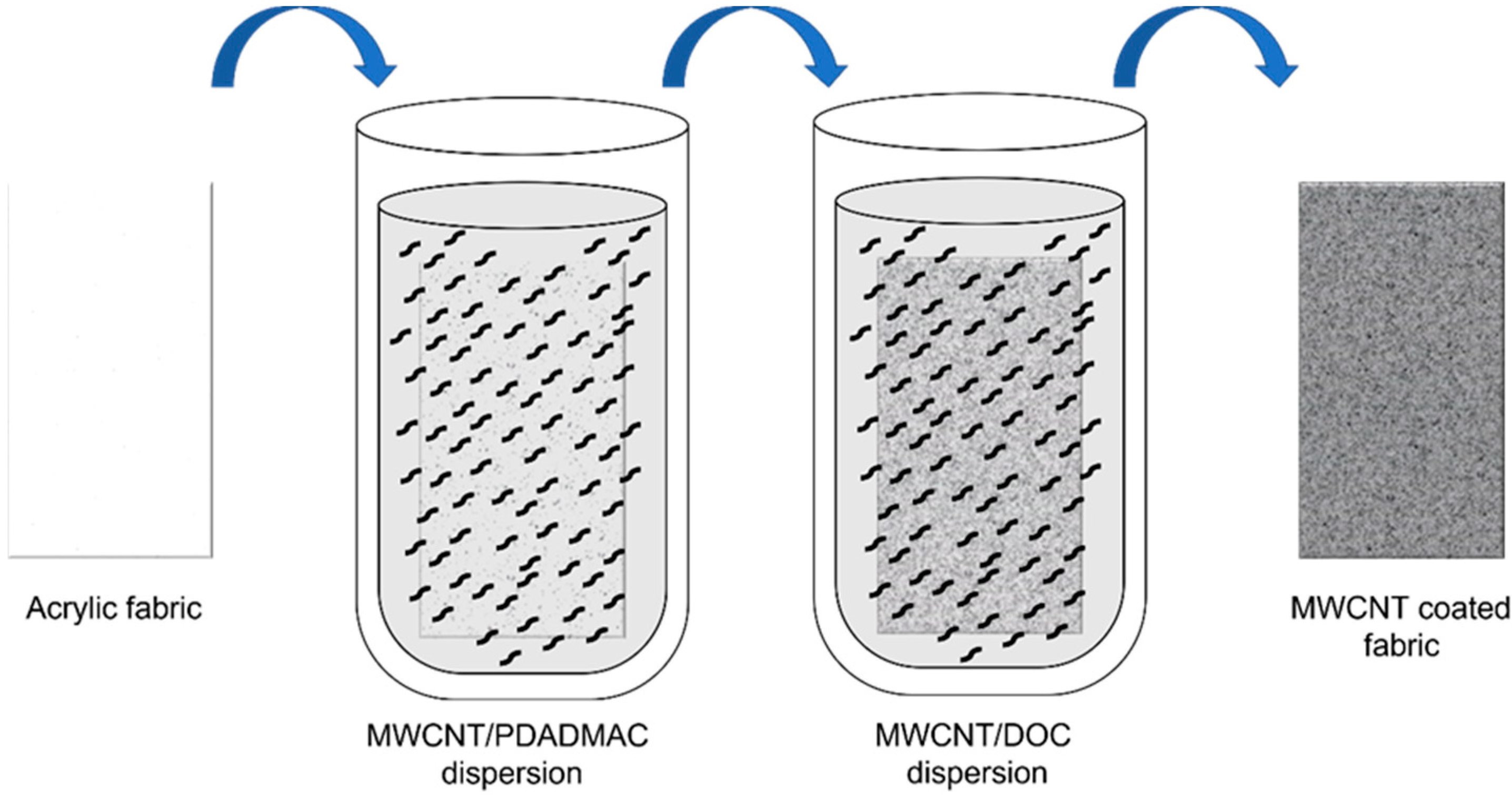
Two MWCNT dispersions (0.05 wt%) were prepared in an aqueous medium using PDADMAC (0.25 wt%) as a cationic stabilizer and DOC (0.25 wt%) as an anionic stabilizer [19]. First, the weighed quantity of carbon nanotubes and surfactant, together with 1 mL of low conductivity water, were introduced into a ball mill mortar, and a pre-dispersion was carried out by ball-milling for 30 min, obtaining a mixture with a paste texture. Next, the paste was introduced into a beaker containing the rest of the water and homogenized in an ultrasound bath for 15 min. Then, the dispersions were ultrasonicated (10 min, ½-inch tip, 90% amplitude, 1.0/0.1 s pulse/pause sequence, BRANSON SFX 550 (Branson Ultrasonics, Brookfield, CT, USA) to obtain a homogeneous dispersion of the nanotubes in the aqueous medium. After preparation of the nanotube dispersions, the fabrics were dipped in a solution of MWCNT/PDADMAC for 2 min, and the fabric was then washed with water and drained. The MWCNT coating on the felt fabric is produced thanks to the electrostatic interaction between functionalized carbon nanotubes with positive and negative charges. Therefore, the coating degree will depend on the number of charges to neutralize. In the optimization prior to this work, we studied different dipping times and observed that 2 min was the optimal time for all the positive (negative) charges to be neutralized by the negative (positive) charges of the next layer. Shorter times led to excessively high electrical resistance, and longer times led to a too long layer-by-layer process without noticeable improvements in the electrical conductivity of the final felt fabric [20]. Afterward, the fabric was immersed in a solution of MWCNT/DOC, and the non-attached substance were removed by several washing steps and drained. These two sequential depositions of MWCNTs, schematically depicted in Figure 1, correspond to one cycle called bilayer (BL).
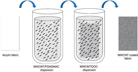
Figure 1.
Schematic process of layer-by-layer (LbL) coating of felt fabrics with MWCNT.
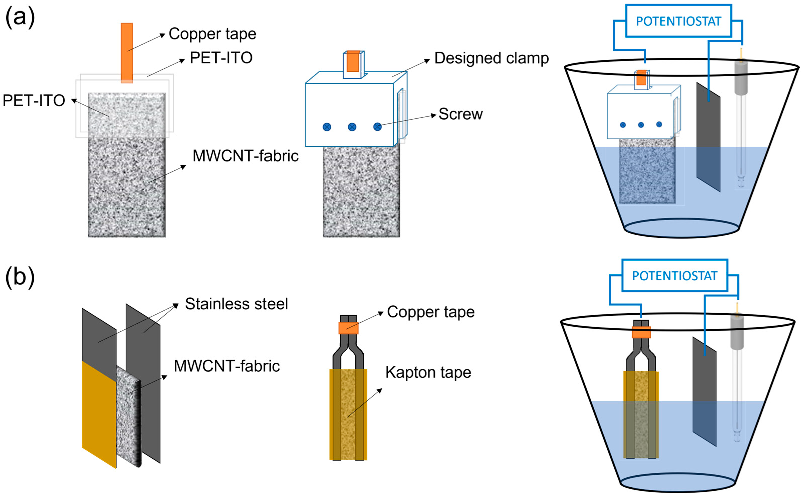
The synthesis of poly (3,4-ethylenedioxythiophene) (PEDOT) and polypyrrole (PPy) on MWCNT–fabrics was carried out by electrochemical polymerization applying a constant current intensity of 6 mA up to 2 h [20]. In contrast, the electrosynthesis of polyaniline (PANI) was carried out using a constant voltage of 2 V. Accordingly, the composition of the solutions for the electrosynthesis of the different conductive polymers is different. For the electrodeposition of PEDOT, a 0.01 M solution of EDOT and 0.1 M of LiClO4 in acetonitrile were used. For the electrodeposition of PPy, the concentration of the monomer, pyrrole, was 0.1 M, and the dopant, LiClO4, 0.1 M, in acetonitrile as solvent. The electrodeposition of PANI was carried out in an aqueous medium with a concentration of 0.5 M of aniline and 1.0 M of H2SO4. Three electrodes formed the electrochemical cell: a counter electrode (platinum), a reference electrode (Ag/AgCl), and the MWCNT–fabric as the working electrode. Two clamps have been designed to hold the carbon nanotube coated textile to avoid contact between the electrochemical solution and the copper electrodes. For the electrodeposition of PEDOT and PPy, the MWCNT–fabric was placed between two pieces of polyethylene terephthalate–indium tin oxide (PET–ITO), one of them connected to a copper tape. Then, PET–ITO sheets with the fabric were held with a clamp, as shown in Figure 2a. In the case of PANI electrodeposition, it was not possible to use this clamp because of the presence of sulfuric acid damages the ITO layer [21]. For this reason, for the electrosynthesis of PANI, the MWCNT-fabric was placed between two stainless steel sheets (Figure 2b), which, on their external part, have an insulating coating that inhibits polymerization and, therefore, electrochemical polymerization only occurs in the part of the steel that is in contact with the fabric. After polymerization, the MWCNT–fabric coated with conductive polymer was rinsed several times with acetonitrile and ethanol to remove the monomers that had not reacted.

Figure 2.
Clamps designed and electrochemical vessel for: (a) electrodeposition of PEDOT and PPy, and (b) electrodeposition of PANI on MWCNT coated fabrics.
2.3. Characterization
Electrical conductivity was evaluated using the Van der Pauw method. In this technique, the electrical conductivity is obtained from the measurement of four-point resistance in two different geometries of the contact arrangement, as shown in Figure S1. For the first resistance measurement, a current IAB was driven from two contacts, A and B. The potential difference VCD between the other contacts, C and D, was measured, obtaining the resistance R1. The second resistance, R2, was determined by driving the current from A to C, IAC, and measuring the voltage between B and D, VBD. According to the Ohm law, the voltage and current values were plotted, giving a linear trend. The electrical conductivity of the sample was obtained by solving the van der Pauw equation [22]:
where d is the sample thickness previously measured, and σ is the electrical conductivity. A Keithley 2400 Source Meter was used as a driving source and voltage measurer.
The Seebeck coefficient has been determined using a homemade device. This device consists of a Peltier as a heater and a copper block cooled by water flow, which acts as a cooler. The sample is placed between these moduli, creating a temperature difference, and the resulting voltage is recorded. The Seebeck coefficient can be determined as the ratio between the electrical potential, ΔV, and the temperature difference, ΔT:
A lakeshore 340 was used as temperature controller. Two PT100 detectors were used to accurately measure the temperature. To record the potential data, an Agilent 34401A Multimeter (Agilent Technologies, Santa Clara, CA, USA) was employed. Both instruments are controlled together using LabView Software (version 2013). Figure S2 shows a schematic of the homemade setup developed for the Seebeck coefficient measurements.
ζ-potential was measured in a Zetasizer Nano ZS (Malvern Instruments, Madrid, Spain) equipment to determine the surface charge of carbon nanotubes. The solutions were diluted to 0.1% by volume with 0.1 mM KCl to keep the ionic strength constant.
Scanning electron microscopy (SEM) images were recorded in a Hitachi S4800 electron microscope (Tokyo, Japan) at an accelerating voltage of 10 kV and a working distance of 15 mm. Tiny sample pieces were placed in the sample holder with carbon adhesive tape and were metalized with Au–Pd coating before observation.
Raman scattering measurements were carried out at room temperature in a backscattering configuration using a Horiba MTB XPlora spectrometer (Horiba Scientific, Kyoto, Japan) coupled to a confocal microscope. An Ar/Kr laser provided the excitation line of 514.53 nm focused onto the sample using a 100x microscope objective. With this technique, we can identify the vibrational modes of carbon nanotubes and conducting polymers.
TGA measurements were performed on a TGA 550 (TA Instruments, Cerdanyola del Valles, Spain) from TA Instruments using platinum pans under a 50 mL min−1 flow of air. The fabrics were tested from room temperature until 700 °C with a ramp of 10 °C min−1.
3. Results and Discussion
In this work, we have developed a method for coating textiles with conductive polymers by electrodeposition. The adhesion of conductive polymers to flexible substrates is generally low [23] and, therefore, we first coated the fibers with carbon nanotubes (CNTs) using the layer-by-layer (LbL) technique. Compatibilizing agents used to disperse carbon nanotubes help to firmly adhere CNTs to textile fibers [24]. After coating with carbon nanotubes, the fabric can be used as a working electrode and conductive polymers can be electrodeposited.
The felt fabric was coated with multiwalled carbon nanotubes (MWCNTs) by layer-by-layer deposition (LbL) to obtain a conductive material. Since the LbL technique is based on the electrostatic interaction between a positive and a negative charge, it is necessary to functionalize the surface of the carbon nanotubes to optimize the coating process. The functionalization of CNT can be of two types: covalent (chemical functionalization), which is based on the covalent bonding of the carbon nanotube with functional groups in the end caps or defects in their sidewalls [25,26,27]; and non-covalent (physical functionalization), which is capable of modifying the interfacial properties of carbon nanotubes through π–π or hydrophobic interactions [25,28,29]. Generally, chemical functionalization degrades the conjugated structure of the nanotubes since they tend to modify the hybridization of sp2 to sp3 and, therefore, decrease the electronic performance of the nanotubes [25]. For this reason, for the functionalization of nanotubes with positive and negative charges, a non-covalent method was chosen, using cationic and anionic surfactants, respectively. Furthermore, for a better tensioactive–nanotube interaction, a mechanochemical method has been used to disperse the carbon nanotubes in water [30].
Two MWCNT dispersions (0.05 wt%) were prepared in an aqueous medium using PDADMAC (0.25 wt%) as a cationic stabilizer and DOC (0.25 wt%) as an anionic stabilizer. The ζ-potential values measured for the dispersions of MWCNT/PDADMAC and MWCNT/DOC were (+32.6 ± 0.8) mV and (−45.2 ± 1.1) mV, respectively. These ζ-potential values indicate that the carbon nanotubes with PDADMAC have a positive surface charge due to the cationic polyelectrolyte, while the MWCNTs with DOC have a negative surface charge due to the coating with the anionic surfactant. This difference in surface charge allows the layer-by-layer method to coat textiles with MWCNT as a result of the electrostatic interaction between MWCNT/PDADMAC and MWCNT/DOC.
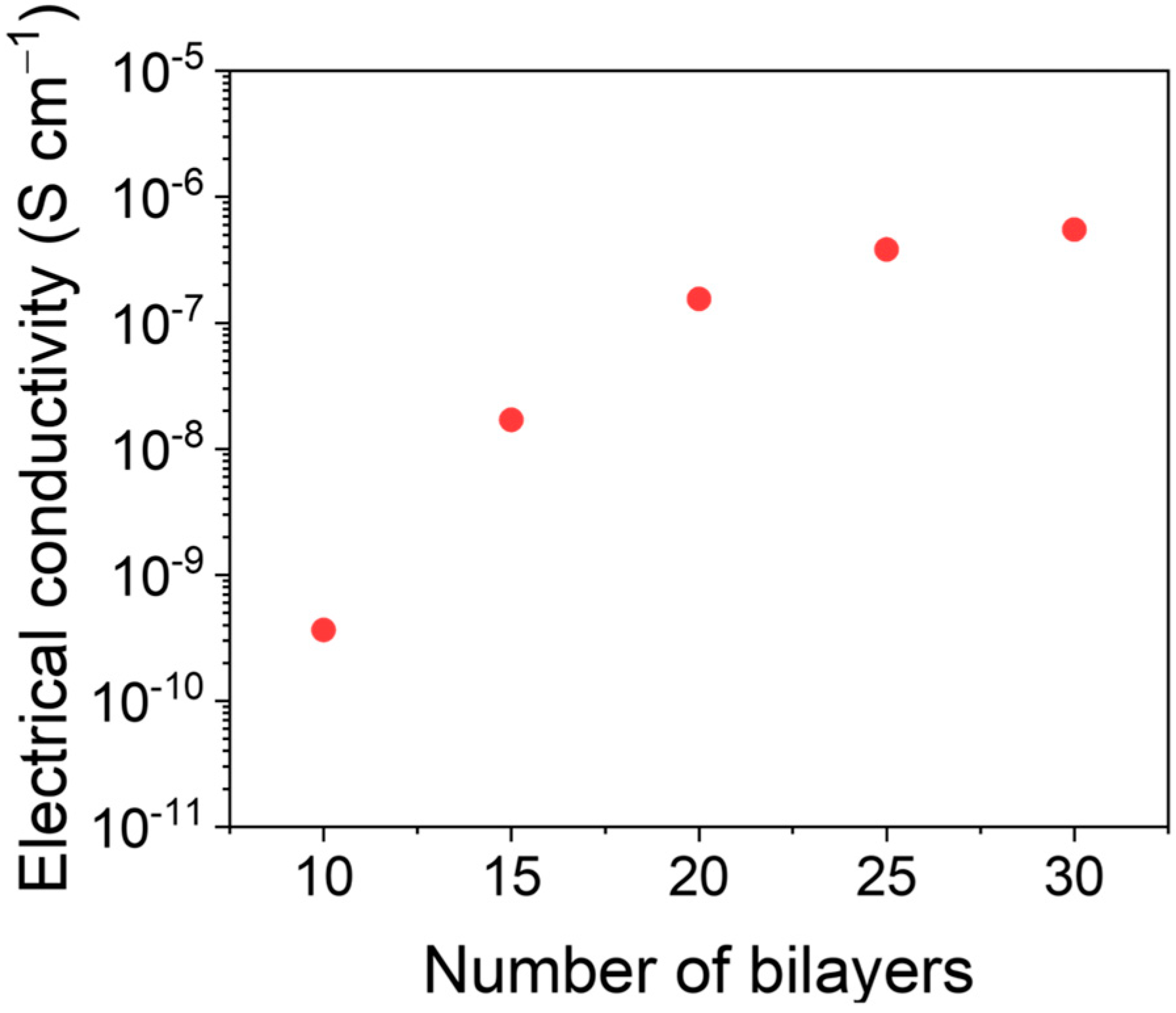
The assembly of MWCNT bilayers (BLs) is controlled by the electrostatic interaction between PDADMAC and DOC. The electrical conductivity was evaluated as a function of the number of bilayers (from 10 to 30) deposited on the fabrics. Figure 3 shows the electrical conductivity as a function of the number of MWCNT on the felt fabric. The electrical conductivity increases until 20 BLs and reaches a plateau at a value around 1.5 × 10⁻⁷ S cm−1, due to a saturation of the fabric with MWCNTs. Since no significant improvement in the conductivity was observed after 20 BLs, we used this value in the subsequent electrodeposition experiments.

Figure 3.
Electrical conductivity as a function of the number of bilayers of MWCNTs onto felt fabric.
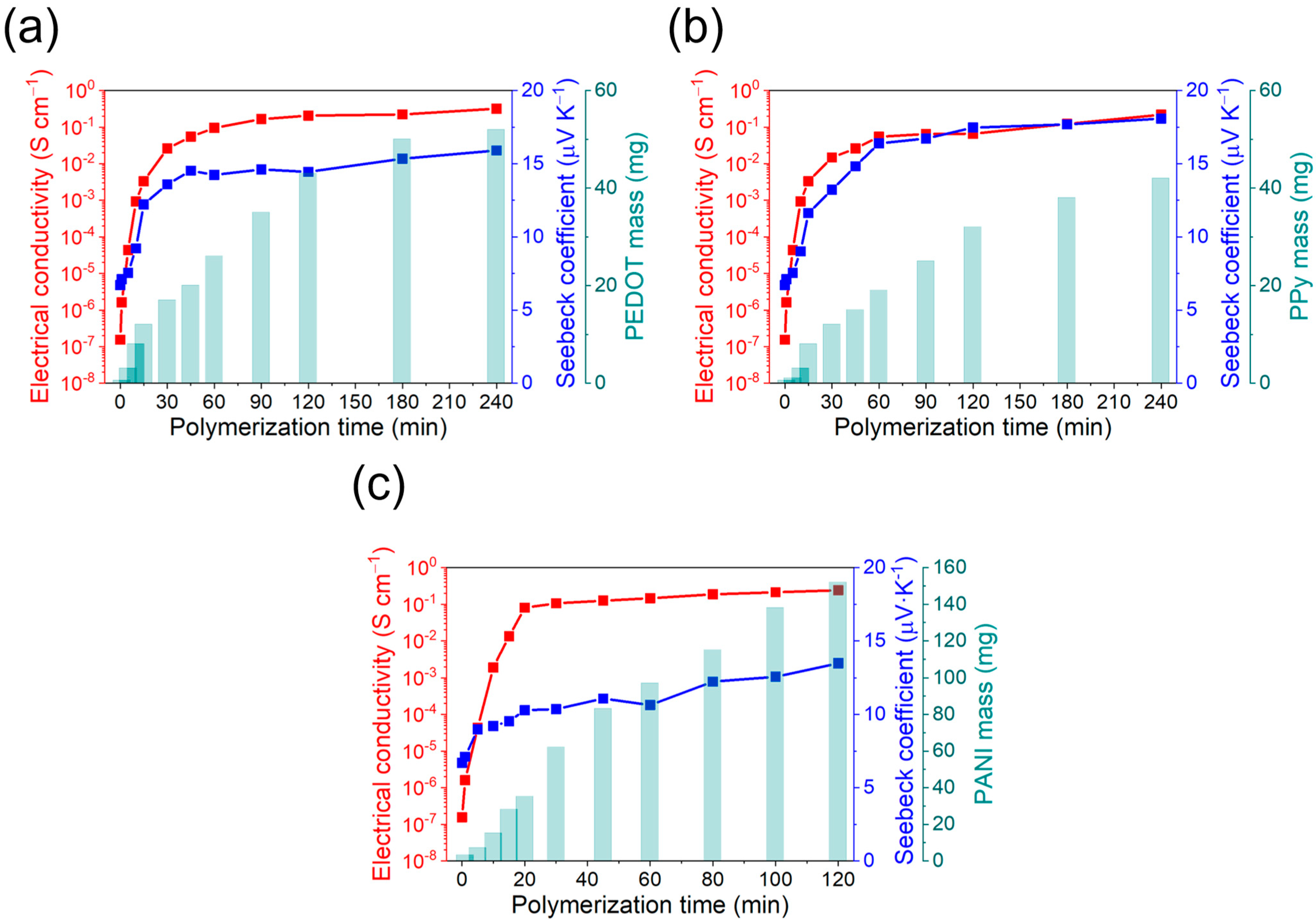
During electropolymerization, an electric current of known potential or intensity is passed through a solution containing the monomer, the dopant, and the solvent, inside an electrolytic cell. The coating of the conductive polymer is generated simultaneously by applying an anodic current that polymerizes the monomer over the working electrode. By controlling the synthesis parameters (potential, intensity, concentration), it is possible to control the quantity of polymer produced and obtain a high reproducibility of the properties [31]. The prepared fabric-MWCNTs were coated with different conductive polymers by electropolymerization. For the case of the PEDOT and PPy deposition, chronopotentiometry was used, while chronoamperometry was used to synthesize PANI. The homogeneity of the fabrics coating with conductive polymers and their thermoelectric properties will depend on the polymerization time. It was therefore necessary to determine the optimal value. For this purpose, the electrical conductivity, the Seebeck coefficient, and the polymer mass deposited as a function of the polymerization time were followed. The corresponding results are shown in Figure 4.
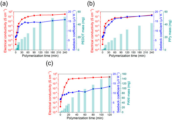
Figure 4.
Electrical conductivity, Seebeck coefficient, and polymer mass deposition as a function of the polymerization time for: (a) PEDOT:ClO4, (b) PPy:ClO4, and (c) PANI:H2SO4.
In general, the mass of conductive polymer deposited on the MWCNT-fabric increases rapidly in the first moments of polymerization and eventually stabilizes. This stabilization is explained because the new generated polymeric chains do not remain attached to the fabric, but in the solution. Regarding electrical conductivity, a similar trend can be observed, with a rapid increase at the initial steps of the polymerization and a stabilization after 30 min, although the mass of polymer deposited increases. The Seebeck coefficient also changes with the polymerization time with an initial value of 7 μV K−1, which corresponds to the Seebeck coefficient of the fabric coated with MWCNTs. However, at higher polymerization times, the Seebeck coefficient achieves a stable value of around 15 μV K−1, corresponding to a highly doped conductive polymer [32].
The optimal polymerization time was decided to be once the electrical conductivity and Seebeck coefficient are maximum with the minimum mass of conductive polymer deposited. These conditions are important because, at high amounts of conductive polymer coating, the felt fibers can worsen the mechanical properties of the final fabric [33]. For the case of PEDOT:ClO4 and PPy:ClO4 coatings, the values of electrical conductivity and Seebeck coefficient stabilize after 60 min of electrochemical polymerization. Although the amount of mass deposited on the fabric increases at longer polymerization times, the thermoelectric properties remain the same. Therefore, an optimal value is reached after 60 min of deposition with an electrical conductivity of 0.1 S cm−1 and a Seebeck coefficient of 14.5 μV K−1 for the PEDOT:ClO4 coating and electrical conductivity of 0.05 S cm−1 and Seebeck coefficient of 16.4 μV K−1 for the Ppy:ClO4 coating. A similar trend is found in the case of the electrochemical deposition of polyaniline. In this case, after 20 min of polymerization, a plateau is reached in the thermoelectric properties despite the deposited mass of PANI increases. The electrical conductivity was 0.08 S cm−1, and the Seebeck coefficient was 12.3 μV K−1. Therefore, the highest thermoelectric efficiency is for PEDOT:ClO4 with a power factor (P = S2σ) of 2.1 10−3 μW m−1 K−2.
The scanning electron microscopy (SEM) images, presented in Figure 5, indicate that the pristine fabric has a practically smooth surface. After deposition of multiwalled carbon nanotubes by LbL, the surface of the fibers becomes rougher. Even at higher magnifications, small threads can be observed, which correspond to the MWCNTs and amorphous agglomerates due to the interaction between the PDADMAC and DOC. Once the fabric fibers are coated with MWCNTs, the fabric acquires a certain electrical conductivity, as shown in Figure 3 and, therefore, it is possible to electropolymerize conductive polymers on the fibers. After the electrodeposition of PEDOT:ClO4, it is observed that the polymer is distributed around the felt fibers coated with MWCNTs with a globular morphology, typical of conductive polymers obtained by electrochemical deposition [34,35]. The electrodeposition of Ppy:ClO4 also takes place around the fibers of Felt-MWCNTs, but a lower degree of coating can be seen since a greater number of uncoated areas are observed. Similar to PEDOT:ClO4, polypyrrole also depicts a globular morphology. After the electrochemical deposition of PANI:H2SO4, it is observed that the coating of the fibers is not homogeneous, and some exfoliation of the layer of MWCNTs deposited on the felt yarn was found. This may be due to the presence of sulfuric acid during the electrochemical polymerization process, which remove the compatibilizing agents that allow the adhesion of MWCNT to the felt fiber, and therefore, the MWCNTs are no longer uniformly attached to the fiber surface.
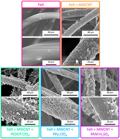
Figure 5.
SEM images of uncoated felt fabric, felt-MWCNTs fabric, and felt-MWCNTs-PEDOT:ClO4, felt-MWCNTs-Ppy:ClO4, and felt-MWCNTs-PANI:H2SO4 fabrics.
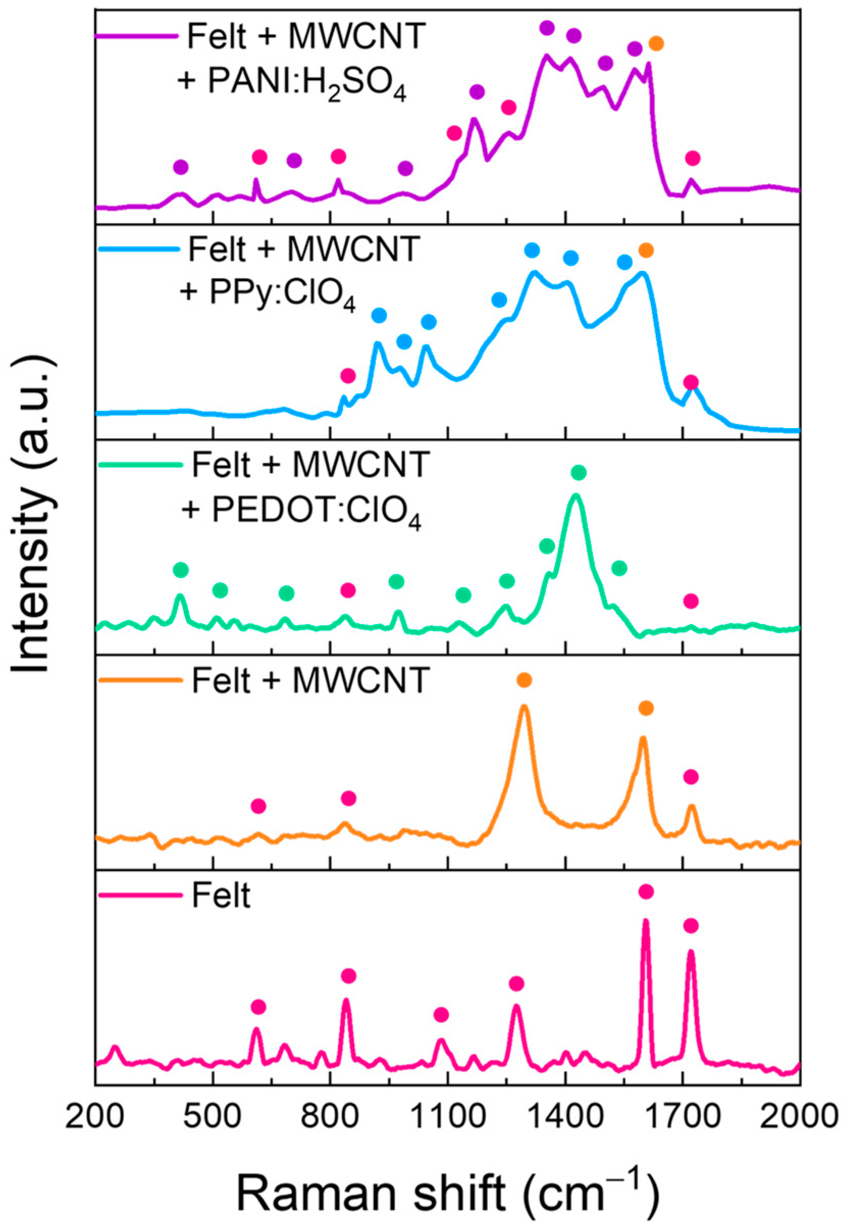
Raman spectroscopy was conducted to obtain information about the composition of the felt fibers coating. Figure 6 shows the Raman spectra of the pristine fabric and the fabric with the different coatings. The main peaks of each sample have been marked with points. The assignation of peaks is detailed in Table 1.
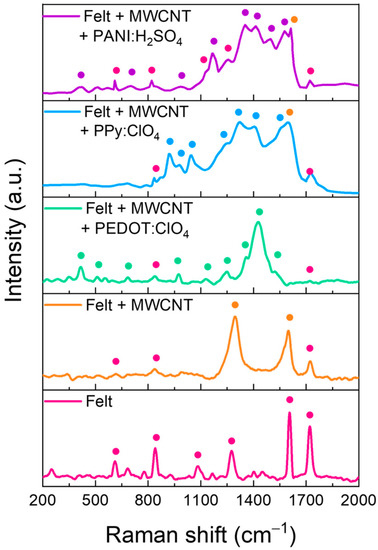
Figure 6.
Raman spectra of felt fabric coated with MWCNTs and after polymers electrodeposition.

Table 1.
Assignation of Raman modes for each material.
Raman spectra of the felt fabric present the typical peaks of polyester, including an aromatic ring in its monomeric unit since two intense peaks appear at 1604 and 1720 cm−1, corresponding to the stretching of the aromatic ring and the carbonyl group, respectively. When the fibers are coated with MWCNTs by LbL, the corresponding Raman spectra show the D and G bands. The first is related to the disorder in sp2-hybridized carbon systems, and the second is related to sp2 vibrations of the graphite crystal and associated with an ordered graphitic structure [36]. However, small peaks related to some felt fibers are also observed. This indicates that the coating with MWCNTs does not cover completely the fibers. After the electrodeposition of PEDOT:ClO4, the residual peaks of the felt fabric decrease in intensity, and practically only the peaks related to the PEDOT polymer chain are observed, see Table 1. On the other hand, after the electrodeposition of Ppy:ClO4, the peaks corresponding to the polypyrrole polymer chain are observed, together with some residual peaks of felt and MWCNTs. For the case of the felt fibers-MWCNTs coated with PANI:H2SO4, the Raman spectrum shows the peaks corresponding to the PANI polymeric chains and numerous peaks corresponding to the felt fibers indicating a poor coverage of the felt fabrics.
These results suggest that the electrochemical coating of the fibers with PEDOT is the most homogeneous since the presence of peaks derived from the felt fabric is residual. On the other hand, the electrodeposition of PANI on the fibers is the one that gives the worst result since the presence of felt peaks is detected. Furthermore, these results agree with the SEM images in Figure 5. Therefore, this methodology is more suitable for the electrochemical coating of felt fibers with PEDOT and PPy, but not for PANI.
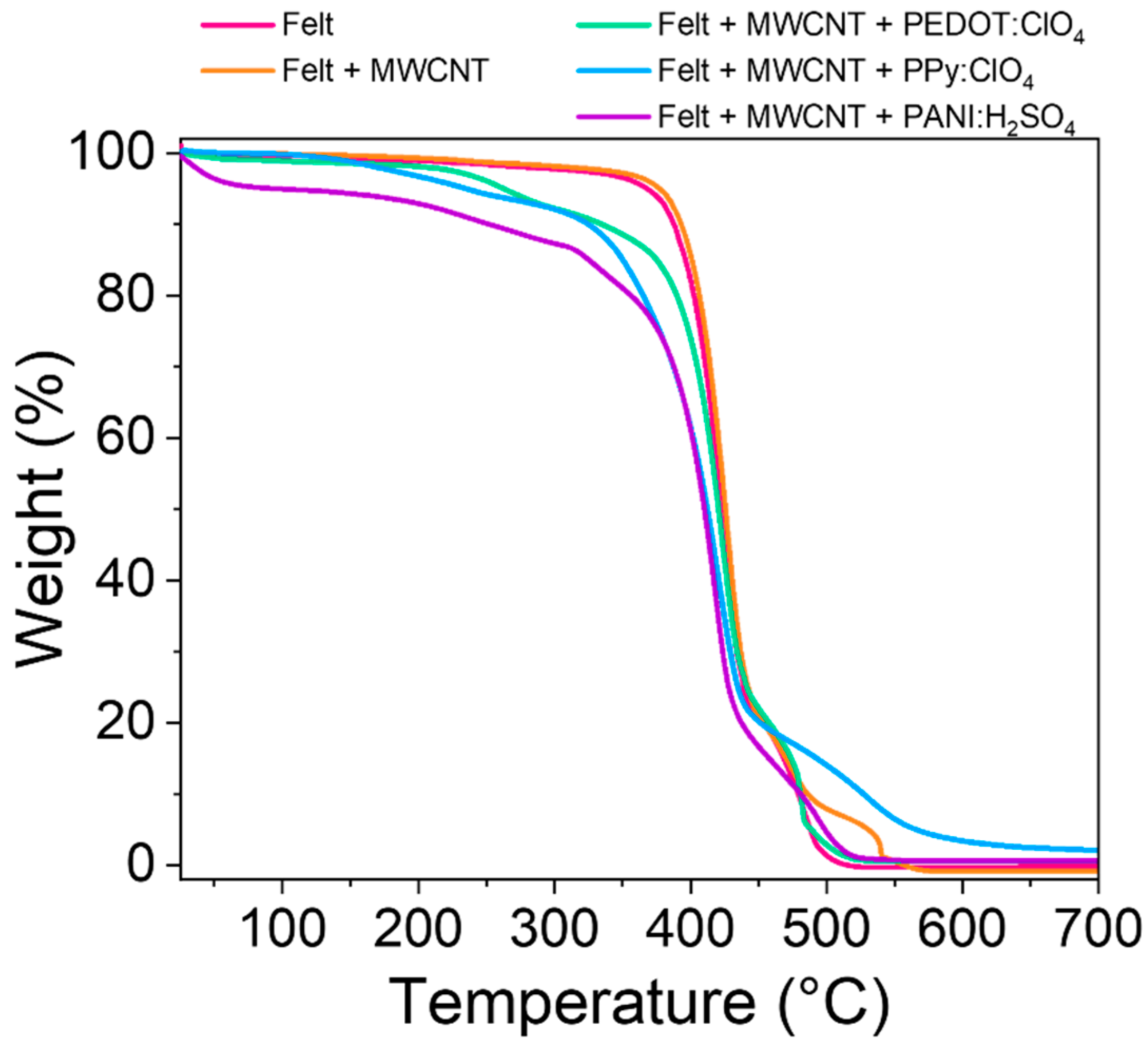
Another important parameter is the thermal stability of the fabrics obtained. This parameter was studied through thermogravimetric analysis (TGA) of the felt and the felt after the different coatings. Figure 7 shows the thermograms of the different samples studied.
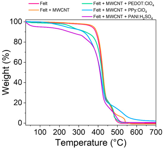
Figure 7.
TGA curves of pristine felt fabric and the felt fabric coated with MWCNT, PEDOT:ClO4, PPy:ClO4, and PANI:H2SO4.
The pristine felt shows an abrupt drop at 450 °C due to the decomposition of the polymeric chains [37]. After coating the fibers with multiwall carbon nanotubes, the thermal stability of the textile increases slightly since the temperature at 5% loss weight (T5%) increases practically 10 °C (Table 2) [38]. The electrochemical coating of felt-MWCNTs fibers with conductive polymers decreases the thermal stability of the fabric. Coating the fibers with PEDOT:ClO4 and PPy:ClO4 reduces the decomposition initiation temperature by approximately 100 and 130 °C, respectively, compared to the pristine fabric. These results suggest that electrosynthesis reduces its thermal stability by coating felt fabrics with PEDOT:ClO4 and PPy:ClO4. However, the decomposition starting temperature of the fabrics coated with these conductive polymers is above the range in temperature that these fabrics are used as thermoelectric materials.
Table 2.
Weight loss temperature at different percentages and residue percentages at 700 °C of pristine felt fabric and the felt fabric coated with MWCNT, PEDOT:ClO4, PPy:ClO4, PANI:H2SO4.
The coating with PANI:H2SO4 drastically reduces the initial decomposition temperature to 92 °C. This result and the exfoliation observed in the SEM images (Figure 5) indicate that the felt fabric is partially degraded during the PANI:H2SO4 electrochemical deposition process [15,39]. In addition, the decomposition initiation temperature is just at the limit of the range of applicability of these fabrics as thermoelectric materials.
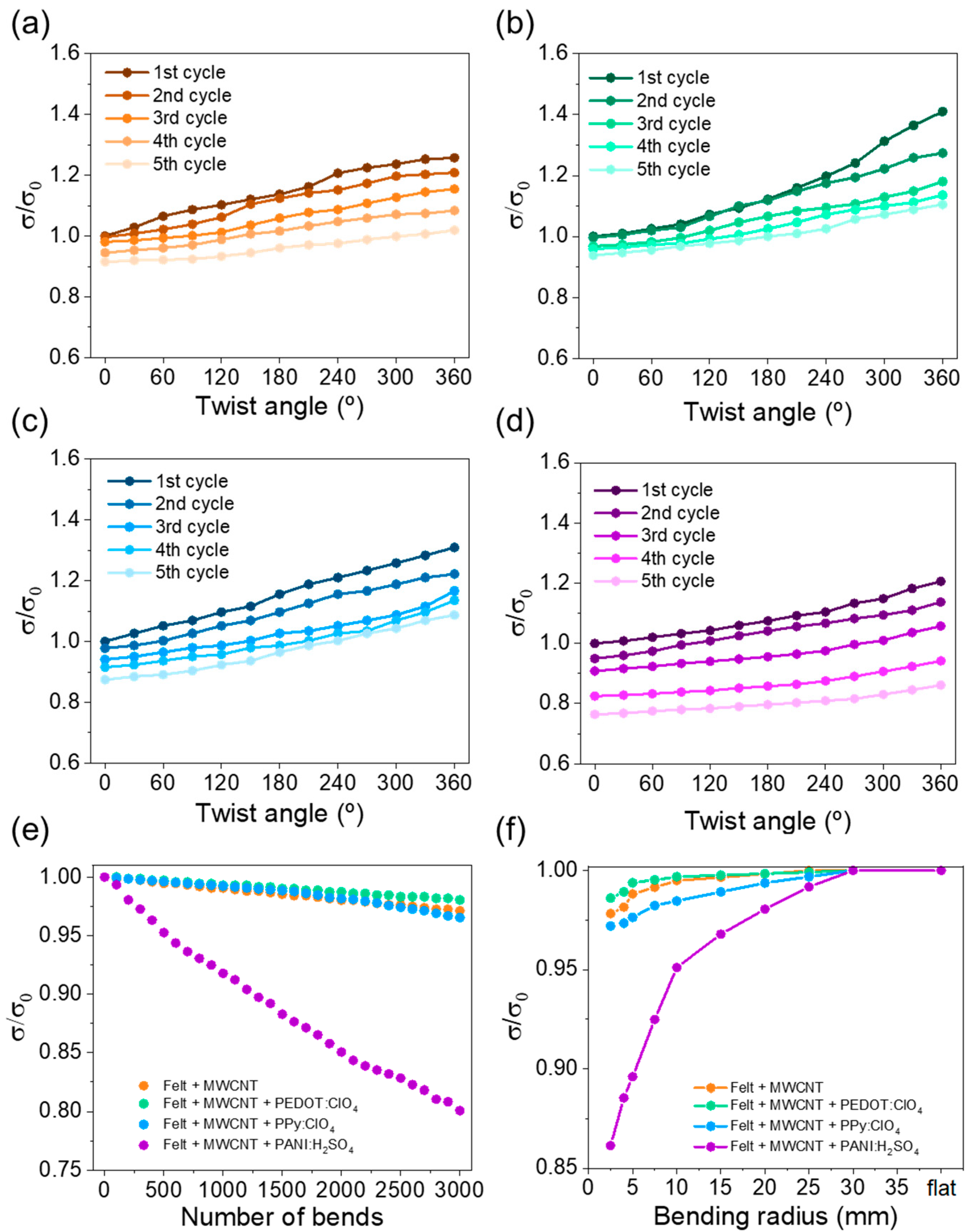
Bending and torsion tests are vital to evaluate their potential use in practical applications since their reliability during daily use must be guaranteed. Therefore, the evolution in the electrical conductivity was evaluated as a function of the twist angle, bending cycles on a 15 mm diameter cylinder, and bending radius. In the first study, the fabric was fixed with two clamps, one fixed and one freely rotating. Electrical conductivity was evaluated every 30° of rotation. Figure 8a–d shows the evolution of the electrical conductivity as a function of the twist angle for the fabrics coated with MWCNT and different conductive polymers. The observed trend indicates that, as the twist angle increases, the electrical conductivity increases due to a higher degree of compaction between the felt fibers, which causes greater electrical contact between the coated fibers. As a consequence, the electron mobility through the fabric improves, reaching higher electrical conductivity. On the other hand, the electrical conductivity slightly decreases after each torsion cycle, probably due to the stress caused on the fibers. After performing the each cycle, the stress caused on the fibers during the torsion generates distension when they return to the original state (0° twist angle), increasing the free space between the fibers. The fabrics coated with MWCNT, PEDOT:ClO4, and Ppy:ClO4 have a high torque capacity since the electrical conductivity decreases around 10% of the initial value. However, the fabric coated with PANI:H2SO4 presents a higher decrease in the electrical conductivity after the cycles performed. This fact agrees with the exfoliation observed in the SEM images.
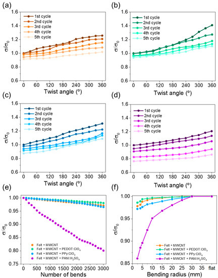
Figure 8.
Variation of normalized electrical conductivity, σ/σ0, as a function of twist angle of: (a) felt + MWCNT, (b) felt + MWCNT + PEDOT:ClO4, (c) felt + MWCNT + PPy:ClO4, and (d) felt + MWCNT + PANI:H2SO4 fabrics. (e) Variation of electrical conductivity as a function of the number of bends, and (f) variation of the electrical conductivity as a function of the bending radius for the different coated felt fabrics.
For the second study, the results are shown in Figure 8e, in which the variation of the normalized electrical conductivity is plotted as a function of the number of bending cycles. The graph shows that the electrical conductivity slightly decreases with the number of bending cycles, reaching a 3% loss after 3000 bending cycles for the fabrics coated wirh MWCNT, PEDOT:ClO4, and PPy:ClO4. In the case of the fabric coated with PANI, the electrical conductivity decreases near 20% of the intial value. Figure 8f shows the electrical conductivity as a function of the bending radius. In this case, it is also observed that the fabrics coated with MWCNT, PEDOT:ClO4, and PPy:ClO4 present a similar electrical conductivity variation. Overall, the results indicate that the electrochemically coated fabrics with PEDOT:ClO4 and PPy:ClO4 have an enormous potential for wearable applications since the electrical conductivity remains practically the same after the different torsion and bending tests. However, the electrochemical coating of fabrics with PANI:H2SO4 do not show the same performance.
4. Conclusions
This work presents a methodology to obtain textiles electrochemically coated by conductive polymers. The method involves coating textile fibers with carbon nanotubes by using the layer-by-layer technique, so that the MWCNT-coated textile can be applied as a working electrode on which different conductive polymers can be electrodeposited. The variation of the electrodeposition time allowed us to determine the adequate times for optimizing the electrical conductivity and the Seebeck coefficient: 60 min for PEDOT and PPy and 30 min for PANI. The quality of the different coatings was evaluated by SEM and Raman spectroscopy. The results indicate that the coating of the textile fibers with MWCNTs, PEDOT, and PPy were very homogeneous, unlike those of PANI. In addition, the thermal stability study carried out by TGA showed that the felt fabric coated with PANI:H2SO4 is the least stable. Finally, the evolution of the electrical conductivity as a function of the twist angle, bending cycles, and bending radius demostrated the potential use of the coated fabrics in practical wearable applications. The results showed that the fabrics coated with PEDOT:ClO4 and PPy:ClO4 are the best candidates to coat fabrics by electrochemical deposition.
Supplementary Materials
The following supporting information can be downloaded at: https://www.mdpi.com/article/10.3390/coatings13020383/s1, Figure S1: Contacts configurations to measure electrical resistance R1 and R2; Figure S2: Scheme of the homemade setup to measure Seebeck coefficient.
Author Contributions
Conceptualization, J.F.S.-C., M.C. and C.M.G.; methodology, J.F.S.-C., R.M.-E., M.C. and C.M.G.; validation, J.F.S.-C., R.M.-E., A.C., M.C. and C.M.G.; formal analysis, J.F.S.-C., R.M.-E., A.C., M.C. and C.M.G. investigation, J.F.S.-C., R.M.-E., A.C., M.C. and C.M.G.; writing—original draft preparation, J.F.S.-C.; writing—review and editing, J.F.S.-C., R.M.-E., A.C., M.C. and C.M.G.; supervision, M.C. and C.M.G.; funding acquisition, A.C. All authors have read and agreed to the published version of the manuscript.
Funding
This research was funded by the Spanish Ministry of Science and Innovation (RTI2018-093711-B-I00) and by the Generalitat Valenciana (Consolidated Group Grant, grant no. AICO/2021/237). The work also received financial support from the Advanced Materials Program (grant no. MFA/2022/064), supported by the Spanish Ministry of Science and Innovation with funding from the European Union (NextGenerationEU, PRTR-C17.I1), and by the Generalitat Valenciana.
Institutional Review Board Statement
Not applicable.
Informed Consent Statement
Not applicable.
Data Availability Statement
Not applicable.
Acknowledgments
J.F.S.-C. acknowledges the financial support by the Spanish Ministry of Education and Vocational Training through the FPU Training (FPU17/01414) and Mobility (EST19/00037) Programs.
Conflicts of Interest
The authors declare no conflict of interest.
References
- Gao, W.; Emaminejad, S.; Nyein, H.Y.Y.; Challa, S.; Chen, K.; Peck, A.; Fahad, H.M.; Ota, H.; Shiraki, H.; Kiriya, D.; et al. Fully Integrated Wearable Sensor Arrays for Multiplexed in Situ Perspiration Analysis. Nature 2016, 529, 509–514. [Google Scholar] [CrossRef] [PubMed]
- Dargusch, M.; Liu, W.; Chen, Z. Thermoelectric Generators: Alternative Power Supply for Wearable Electrocardiographic Systems. Adv. Sci. 2020, 7, 2001362. [Google Scholar] [CrossRef] [PubMed]
- Starner, T. Human-Powered Wearable Computing. IBM Syst. J. 1996, 35, 618–629. [Google Scholar] [CrossRef]
- Wang, Z.L. On Maxwell’s Displacement Current for Energy and Sensors: The Origin of Nanogenerators. Mater. Today 2017, 20, 74–82. [Google Scholar] [CrossRef]
- Dong, K.; Peng, X.; An, J.; Wang, A.C.; Luo, J.; Sun, B.; Wang, J.; Wang, Z.L. Shape Adaptable and Highly Resilient 3D Braided Triboelectric Nanogenerators as E-Textiles for Power and Sensing. Nat. Commun. 2020, 11, 2868. [Google Scholar] [CrossRef]
- Lin, Y.-F.; Song, J.; Ding, Y.; Lu, S.-Y.; Wang, Z.L. Piezoelectric Nanogenerator Using CdS Nanowires. Appl. Phys. Lett. 2008, 92, 022105. [Google Scholar] [CrossRef]
- Lin, S.; Zhang, L.; Zeng, W.; Shi, D.; Liu, S.; Ding, X.; Yang, B.; Liu, J.; Lam, K.; Huang, B.; et al. Flexible Thermoelectric Generator with High Seebeck Coefficients Made from Polymer Composites and Heat-Sink Fabrics. Commun. Mater. 2022, 3, 44. [Google Scholar] [CrossRef]
- Tao, X. Wearable Electronics and Photonics; Woodhead Publishing Series in Textiles; Elsevier Science: Amsterdam, The Netherlands, 2005; ISBN 9781845690441. [Google Scholar]
- Wang, Z.L.; Wu, W. Nanotechnology-Enabled Energy Harvesting for Self-Powered Micro-/Nanosystems. Angew. Chem. Int. Ed. 2012, 51, 11700–11721. [Google Scholar] [CrossRef]
- Snyder, G.J.; Toberer, E.S. Complex Thermoelectric Materials. In Materials for Sustainable Energy; Co-Published with Macmillan Publishers Ltd.: London, UK, 2010; pp. 101–110. [Google Scholar]
- Kim, D.-H.; Ghaffari, R.; Lu, N.; Rogers, J.A. Flexible and Stretchable Electronics for Biointegrated Devices. Annu. Rev. Biomed. Eng. 2012, 14, 113–128. [Google Scholar] [CrossRef]
- Wei, T.-R.; Jin, M.; Wang, Y.; Chen, H.; Gao, Z.; Zhao, K.; Qiu, P.; Shan, Z.; Jiang, J.; Li, R.; et al. Exceptional Plasticity in the Bulk Single-Crystalline van Der Waals Semiconductor InSe. Science 2020, 369, 542–545. [Google Scholar] [CrossRef]
- Zhang, J.; Zhang, T.; Zhang, H.; Wang, Z.; Li, C.; Wang, Z.; Li, K.; Huang, X.; Chen, M.; Chen, Z.; et al. Single-Crystal SnSe Thermoelectric Fibers via Laser-Induced Directional Crystallization: From 1D Fibers to Multidimensional Fabrics. Adv. Mater. 2020, 36, 2002702. [Google Scholar] [CrossRef]
- Culebras, M.; Gómez, C.M.; Cantarero, A. Review on Polymers for Thermoelectric Applications. Materials 2014, 7, 6701–6732. [Google Scholar] [CrossRef]
- Allison, L.; Hoxie, S.; Andrew, T.L. Towards Seamlessly-Integrated Textile Electronics: Methods to Coat Fabrics and Fibers with Conducting Polymers for Electronic Applications. Chem. Commun. 2017, 53, 7182–7193. [Google Scholar] [CrossRef]
- Tao, X. (Ed.) Handbook of Smart Textiles; Springer: Singapore, 2015; ISBN 978-981-4451-44-4. [Google Scholar]
- Lage-Rivera, S.; Ares-Pernas, A.; Abad, M. Last Developments in Polymers for Wearable Energy Storage Devices. Int. J. Energy Res. 2022, 46, 10475–10498. [Google Scholar] [CrossRef]
- Jia, Y.; Jiang, Q.; Sun, H.; Liu, P.; Hu, D.; Pei, Y.; Liu, W.; Crispin, X.; Fabiano, S.; Ma, Y.; et al. Wearable Thermoelectric Materials and Devices for Self-Powered Electronic Systems. Adv. Mater. 2021, 33, 2102990. [Google Scholar] [CrossRef]
- Serrano-Claumarchirant, J.F.; Culebras, M.; Cantarero, A.; Gómez, C.M.; Muñoz-Espí, R. Poly(3,4-Ethylenedioxythiophene) Nanoparticles as Building Blocks for Hybrid Thermoelectric Flexible Films. Coatings 2019, 10, 22. [Google Scholar] [CrossRef]
- Serrano-Claumarchirant, J.F.; Brotons-Alcázar, I.; Culebras, M.; Sanchis, M.J.; Cantarero, A.; Muñoz-Espí, R.; Gómez, C.M. Electrochemical Synthesis of an Organic Thermoelectric Power Generator. ACS Appl. Mater. Interfaces 2020, 12, 46348–46356. [Google Scholar] [CrossRef]
- Tsai, T.-H.; Wu, Y.-F. Wet Etching Mechanisms of ITO Films in Oxalic Acid. Microelectron. Eng. 2006, 83, 536–541. [Google Scholar] [CrossRef]
- van der Pauw, L.J. A Method of Measuring Specific Resistivity and Hall Effect of Discs of Arbitrary Shape. Philips Res. Rep. 1958, 13, 1–9. [Google Scholar]
- Jia, Y.; Shen, L.; Liu, J.; Zhou, W.; Du, Y.; Xu, J.; Liu, C.; Zhang, G.; Zhang, Z.; Jiang, F. An Efficient PEDOT-Coated Textile for Wearable Thermoelectric Generators and Strain Sensors. J. Mater. Chem. C 2019, 7, 3496–3502. [Google Scholar] [CrossRef]
- Sadi, M.S.; Pan, J.; Xu, A.; Cheng, D.; Cai, G.; Wang, X. Direct Dip-Coating of Carbon Nanotubes onto Polydopamine-Templated Cotton Fabrics for Wearable Applications. Cellulose 2019, 26, 7569–7579. [Google Scholar] [CrossRef]
- Jeon, I.-Y.; Chang, D.W.; Kumar, N.A.; Baek, J.-B. Functionalization of Carbon Nanotubes. In Carbon Nanotubes; Yellampalli, S., Ed.; IntechOpen: Rijeka, Croatia, 2011. [Google Scholar]
- Prato, M.; Kostarelos, K.; Bianco, A. Functionalized Carbon Nanotubes in Drug Design and Discovery. Acc. Chem. Res. 2008, 41, 60–68. [Google Scholar] [CrossRef] [PubMed]
- Engtrakul, C.; Davis, M.F.; Gennett, T.; Dillon, A.C.; Jones, K.M.; Heben, M.J. Protonation of Carbon Single-Walled Nanotubes Studied Using 13C and 1H−13C Cross Polarization Nuclear Magnetic Resonance and Raman Spectroscopies. J. Am. Chem. Soc. 2005, 127, 17548–17555. [Google Scholar] [CrossRef] [PubMed]
- Yi, W.; Malkovskiy, A.; Chu, Q.; Sokolov, A.P.; Colon, M.L.; Meador, M.; Pang, Y. Wrapping of Single-Walled Carbon Nanotubes by a π-Conjugated Polymer: The Role of Polymer Conformation-Controlled Size Selectivity. J. Phys. Chem. B 2008, 112, 12263–12269. [Google Scholar] [CrossRef] [PubMed]
- Yu, J.; Grossiord, N.; Koning, C.E.; Loos, J. Controlling the Dispersion of Multi-Wall Carbon Nanotubes in Aqueous Surfactant Solution. Carbon N. Y. 2007, 45, 618–623. [Google Scholar] [CrossRef]
- Munkhbayar, B.; Nine, M.J.; Jeoun, J.; Bat-Erdene, M.; Chung, H.; Jeong, H. Influence of Dry and Wet Ball Milling on Dispersion Characteristics of the Multi-Walled Carbon Nanotubes in Aqueous Solution with and without Surfactant. Powder Technol. 2013, 234, 132–140. [Google Scholar] [CrossRef]
- Ferraris, J.P.; Hanlon, T.R. Optical, Electrical and Electrochemical Properties of Heteroaromatic Copolymers. Polymer 1989, 30, 1319–1327. [Google Scholar] [CrossRef]
- Horta-Romarís, L.; González-Rodríguez, M.V.; Lasagabáster, A.; Rivadulla, F.; Abad, M.-J. Thermoelectric Properties and Intrinsic Conduction Processes in DBSA and NaSIPA Doped Polyanilines. Synth. Met. 2018, 243, 44–50. [Google Scholar] [CrossRef]
- Wang, L.; Lin, T.; Wang, X.; Kaynak, A. Frictional and Tensile Properties of Conducting Polymer Coated Wool and Alpaca Fibers. Fibers Polym. 2005, 6, 259–262. [Google Scholar] [CrossRef]
- Castagnola, V.; Bayon, C.; Descamps, E.; Bergaud, C. Morphology and Conductivity of PEDOT Layers Produced by Different Electrochemical Routes. Synth. Met. 2014, 189, 7–16. [Google Scholar] [CrossRef]
- Vlamidis, Y.; Lanzi, M.; Salatelli, E.; Gualandi, I.; Fraboni, B.; Setti, L.; Tonelli, D. Electrodeposition of PEDOT Perchlorate as an Alternative Route to PEDOT:PSS for the Development of Bulk Heterojunction Solar Cells. J. Solid State Electrochem. 2015, 19, 1685–1693. [Google Scholar] [CrossRef]
- Montes-Morán, M.A.; Young, R.J. Raman Spectroscopy Study of HM Carbon Fibres: Effect of Plasma Treatment on the Interfacial Properties of Single Fibre/Epoxy Composites. Carbon N. Y. 2002, 40, 845–855. [Google Scholar] [CrossRef]
- Das, P.; Tiwari, P. Thermal Degradation Study of Waste Polyethylene Terephthalate (PET) under Inert and Oxidative Environments. Thermochim. Acta 2019, 679, 178340. [Google Scholar] [CrossRef]
- Zhou, T.Y.; Tsui, G.C.P.; Liang, J.Z.; Zou, S.Y.; Tang, C.Y.; Mišković-Stanković, V. Thermal Properties and Thermal Stability of PP/MWCNT Composites. Compos. Part B Eng. 2016, 90, 107–114. [Google Scholar] [CrossRef]
- Hong, K.H.; Oh, K.W.; Kang, T.J. Preparation and Properties of Electrically Conducting Textiles Byin Situ Polymerization of Poly(3,4-Ethylenedioxythiophene). J. Appl. Polym. Sci. 2005, 97, 1326–1332. [Google Scholar] [CrossRef]

Disclaimer/Publisher’s Note: The statements, opinions and data contained in all publications are solely those of the individual author(s) and contributor(s) and not of MDPI and/or the editor(s). MDPI and/or the editor(s) disclaim responsibility for any injury to people or property resulting from any ideas, methods, instructions or products referred to in the content. |
© 2023 by the authors. Licensee MDPI, Basel, Switzerland. This article is an open access article distributed under the terms and conditions of the Creative Commons Attribution (CC BY) license (https://creativecommons.org/licenses/by/4.0/).