Article

Effect of the Welding Thermal Cycle on the Microstructure and Mechanical Properties of TiC Cermet HAZ Using the Gleeble Simulator

1
School of Material Science & Enginreering, Zhengzhou University, Zhengzhou 450000, China
2
Zhengzhou Research Institute of Mechanical Engineering, Zhengzhou 450000, China
*
Author to whom correspondence should be addressed.
Coatings 2023, 13(2), 476; https://doi.org/10.3390/coatings13020476
Submission received: 11 January 2023 / Revised: 3 February 2023 / Accepted: 12 February 2023 / Published: 20 February 2023
(This article belongs to the Section Ceramic Coatings and Engineering Technology)

Abstract

:
The effect of heat input on the microstructure and mechanical properties of TiC cermet in MIG welding has been comprehensively investigated by Gleeble simulation. The microstructure, phase composition and shear fracture of TiC cermet were examined by OM (optical microscopy), SEM (scanning electron microscope), TEM (transmission electron microscope) and XRD (X-ray diffraction) analyses. The results show that the heat input has a significant effect on the properties of TiC cermet. With TiC particles and the austenite bonding phase remaining the same, the heat input can effectively improve the toughness of the bonding phase and the structural strength from 219.9 HV0.01 to 380.5 HV0.01 and from 469 MPa to 684 MPa, respectively, as the dislocation density increases while the heat input increases. When the heat input is 3.4 KJ/cm, the shear strength reaches the peak at 684 MPa, with the increase in heat input, the secondary fragmentation of TiC particles increases, and the crack propagation leads to a significant decrease in material strength.

1. Introduction

The demand for high-performance wear-resistant materials is continually growing. High wear, high strength and high hardness are needed in certain operational environments. TiC ceramic, as the front-runner of ultra-high temperature ceramics (UHTC), has attractive characteristics of high thermal and chemical stability, low density, high hardness and excellent wear resistance [1,2]. Given these properties, components made of TiC cermet are intended for use in aerospace, metallurgy, mining, shield tunneling, nuclear power and other fields [3,4,5,6,7,8,9].
Establishing a reliable connection between TiC ceramics and steel can give full play to the complementary advantages of the two materials in terms of performance and economy, as TiC cermet exhibits the combined advantages of the TiC ceramic phase (high hardness, excellent wear resistance and outstanding chemical stability) with the binder phase (high strength, high toughness, good machinability and thermal stability); therefore, TiC cermet shows excellent comprehensive performance [10].
The widespread use of TiC cermet is hindered by its inherent brittleness, low ductility, and poor processing and welding ability [11,12] because the physical and chemical properties of TiC cermet and metals are different. The chemical properties of TiC cermet and metals vary considerably, and the chemical reactions in the welding process can easily form various complex brittle compounds at the interface between the two materials. These oxides, carbides, nitrides, silicides and multi-component compounds usually have high hardness and brittleness. Their distribution at the interface is complex, making them vulnerable to stress concentration and leading to fractures of the joints. Domestic and foreign scholars alike have conducted extensive research on the technology of combining TiC cermet and metals to obtain composite components with exceptional performance. Jicai Feng et al. [13] vacuum brazed TiC cermet and stainless steel with a AgCuZn filler metal, with an interface structure of TiC/(Cu, Ni)/Ag (S. S) + Cu (S. S)/(Cu, Ni)/(Cu, Ni) + (Fe, Ni)/stainless steel. The maximum shear strength of the joint was 120.7 MPa. Li Jia et al. [14] bonded TiC cermet to 304 stainless steel by solid-phase diffusion, and the interface structure was formed with the (β-Ti, Nb) phase and an α + β-Ti solid solvent. The Nb layer effectively prevents the diffusion of titanium and iron atoms on both sides and reduces the formation of intermetallic compounds. The shear strength of the joint is 110 MPa. Li Huang et al. [15] bonded TiC cermet to 06Cr19Ni10 stainless steel with a Ti/Cu/Nb inter-layer, and the bonding time was shortened by the pulse pressure method, effectively facilitating the diffusion and reaction between TiC and SS with a maximum shear strength of 106.7 MPa. Kumar S. et al. [16,17] simulated the physical weld thermal cycles as well as the reheated coarse-grained HAZs on bainitic steel with different heat inputs, and the impact toughness decreased with increasing heat inputs attributing to the microstructure changes in CGHAZ regions. So far, the influence of the welding heat input on TiC cermet has gone unexplored.
In the present work, the Gleeble®3500 was used to carry out the MIG welding process for high-manganese steel thermal simulation at four different heat inputs to observe the different microstructural and mechanical properties of TiC cermet HAZs. Microstructural characterization facilities such as optical, scanning and transmission electron microscopy, and mechanical testing facilities such as microhardness and shear strength are used to investigate the structure–properties correlations of TiC cermet HAZs.

2. Materials and Methods

2.1. Materials

The cermet used for the experiments was produced by Zhengzhou Research Institute of Mechanical Engineering Co., Ltd. Zhengzhou, China, 450000, the chemical and mechanical properties tested following «GB/T 223» «GB/T 40388-2021» and SATM E1269-11 standards, respectively, results are shown in Table 1.

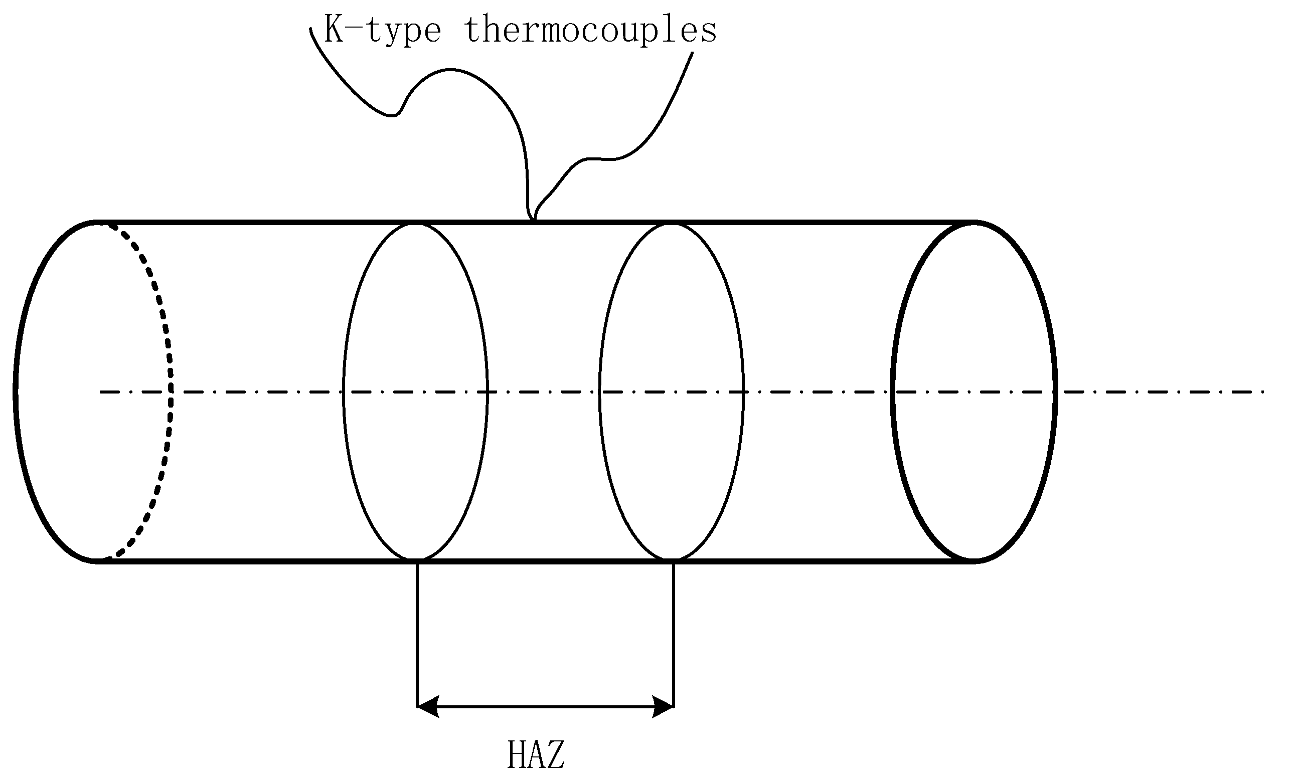
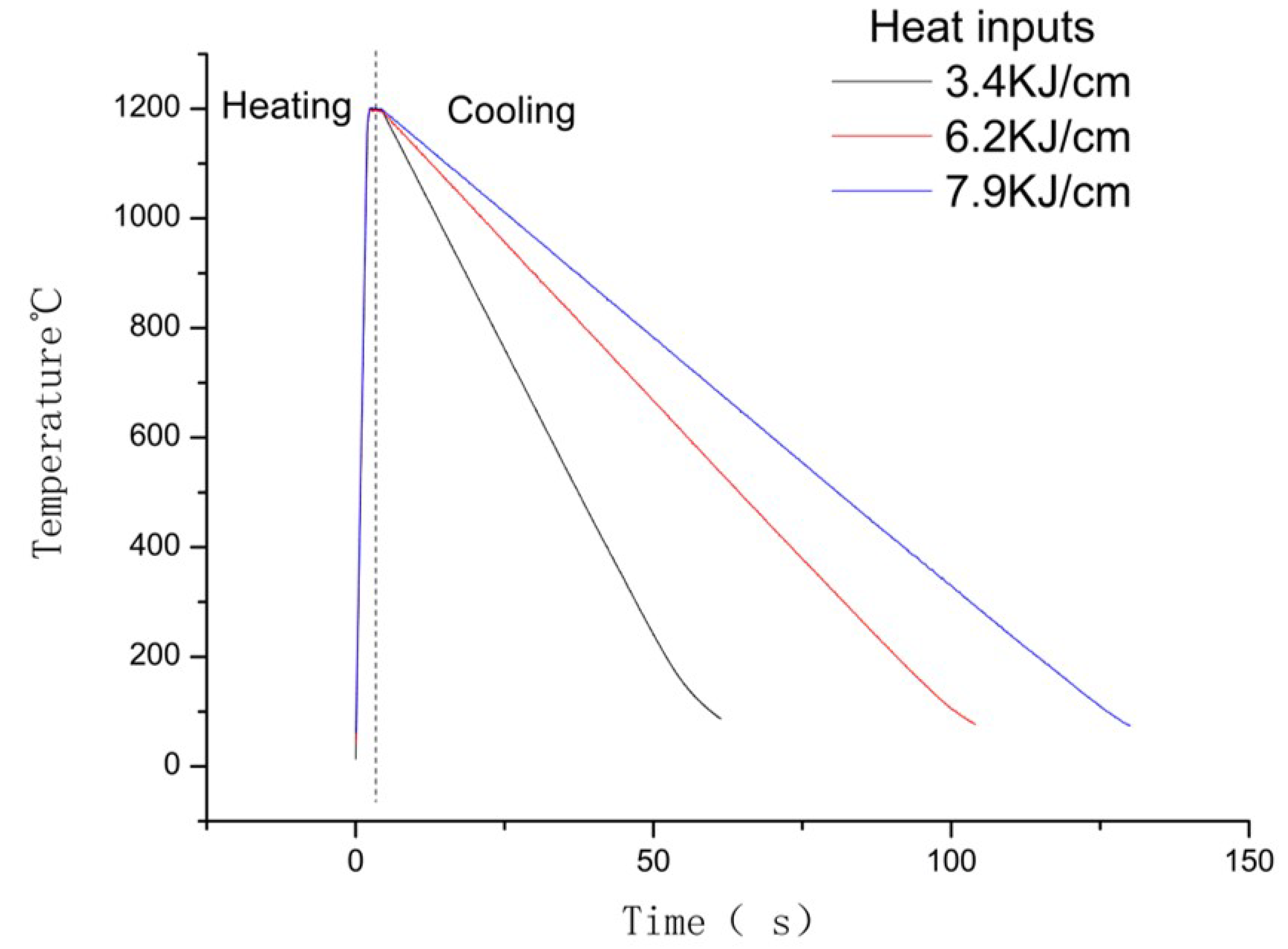
2.2. HAZ Thermal Simulation

Gleeble®3500 was used for thermal simulation, as temperature measurements of a K-type thermocouple were welded onto the middle of a spaceman to record and control the induction heating. The location of thermocouple is shown in Figure 1.
The peak temperature, peak time and cooling rate of the thermal cycle parameters were selected based on the possible MIG welding procedures for high-manganese steel; hence, low heat input was selected at 3.4 KJ/cm, 6.2 KJ/cm and 7.9 KJ/cm. According to previous research [18], TiC particles begin to precipitate at 1120 °C, while the thermocouple would fall off at a peak temperature higher than 1200 °C. In order to simulate the HAZ area, specimens were heated up to 1200 °C at the rate of 500 °C/s and held for 1 s. According to the derivation of welding heat transfer theory, the cool down time between peak temperature and 100 °C (t100) was calculated by applying the formula shown in Equation (1) [17]. The cool down times to 100 ℃ were 52 s, 96 s and 122 s at the cool down ratios of 21.15 °C/s, 11.45 °C/s and 9.01 °C/s, respectively. The heating models of the simulations are given in Table 2 and Figure 2.
t 100 = η E 2 π λ ( 1 100 T 0 1 t m T 0 )
where η is the welding heat efficiency, for welding steel, η was set as 0.68; E, λ and T0 are the welding heat input, the thermal conductivity and the preheating temperature, respectively; and tm is the peak temperature.
Two specimens with approximate dimensions of φ6 mm × 50 mm were cut from the TiC cermet for each variant. From every testing variant, 1 specimen was meant for shear strength testing and hardness testing following «GB/T 40388-2021» and «GB/T4340.1—1999» standards, respectively. The other specimens were used for microstructure, XRD and dislocation density analyses.

3. Results

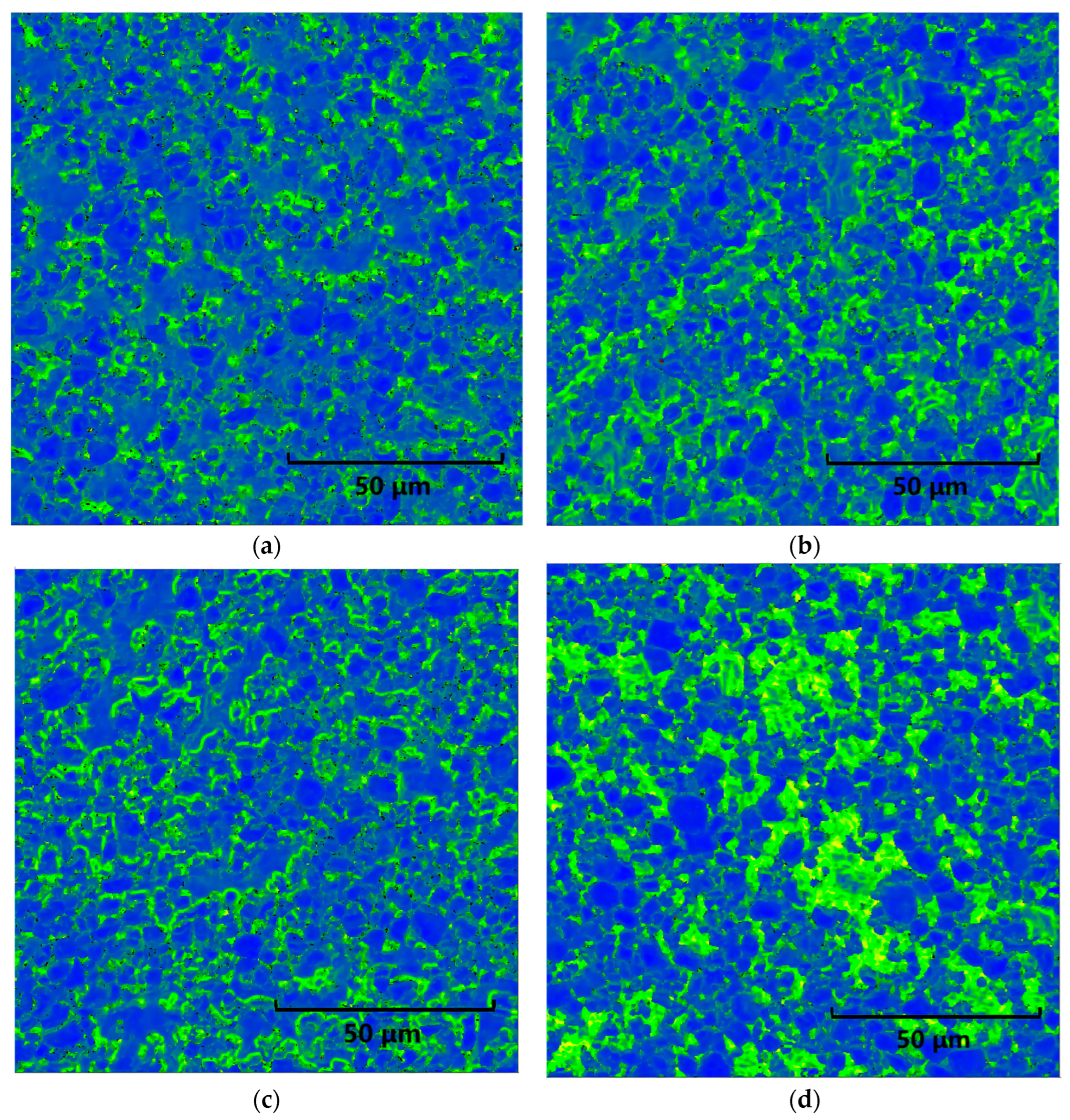
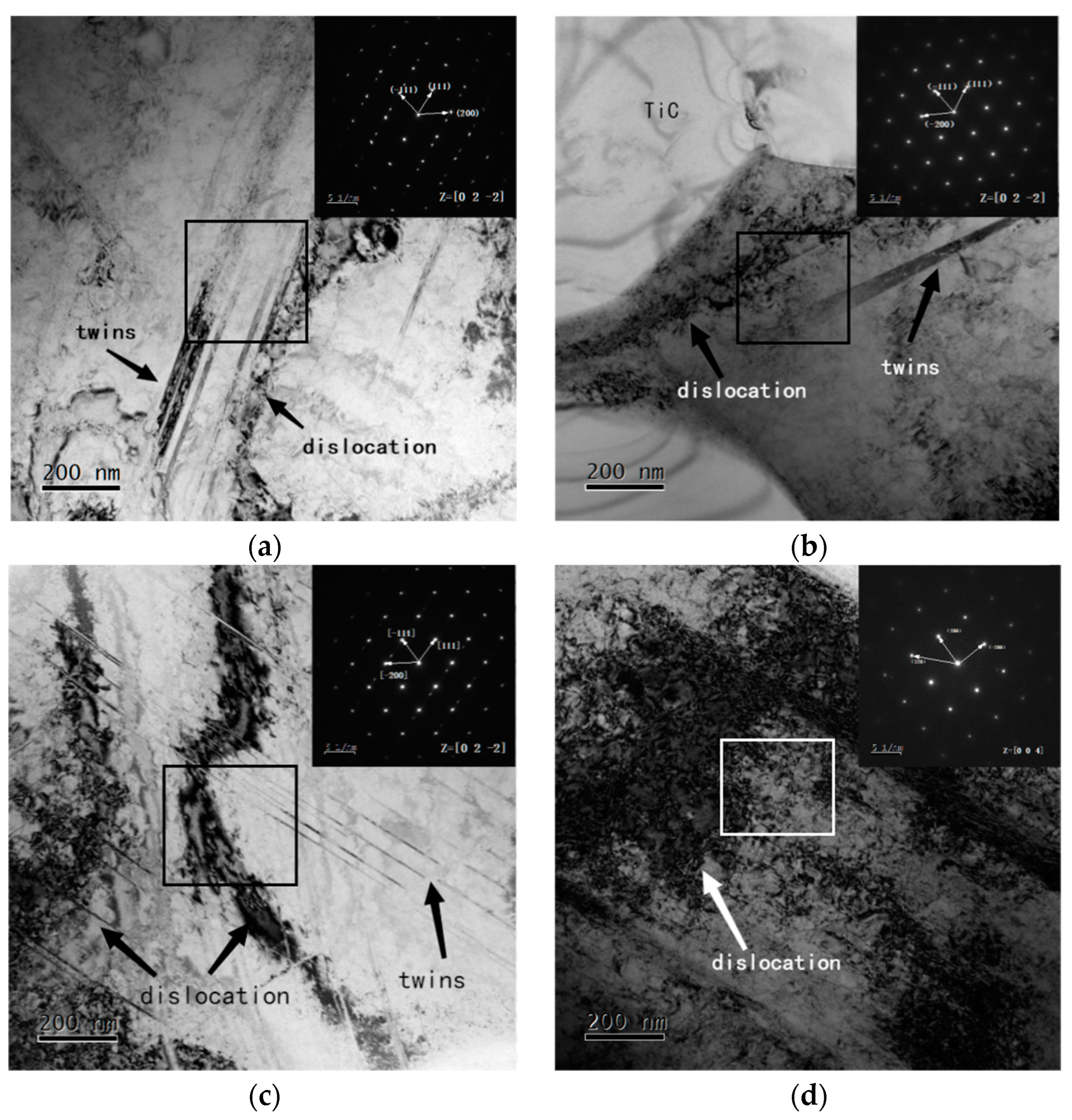
3.1. Microstructures

Figure 3a–d reveal the effect of the heat input rate on the microstructural evolution in the simulated HAZ of TiC cermet with sintered status and heat inputs of 3.4 KJ/cm, 6.2 KJ/cm and 7.9 KJ/cm, respectively. The figures show that TiC cermet are composed of black TiC particles and a light-colored bonding phase, which is the typical characterization of TiC cermet. The microstructure of the specimens remained the same with the increase in heat input. However, the recorded data for the investigated HAZs of TiC cermet showed an increase in C and Ti elements in the bonding phase (see Table 3). The wt% gradually increased from 9.12% to 12.05% and from 0.69% to 1.19% for C and Ti, respectively, and the Mn element decrease from 12.15% in sintered specimen to around 10% in the simulated specimens. According to the previous published work [18], TiC particles begin to precipitate at 1120 °C; therefore, with longer residence times in high temperature, the dissolution rate of the TiC particles increased while the Mn element reformed the TiC particle outer rim phase, resulting in the transition of Ti and C elements into the bonding phase to form a solid solution in bonding phase, which improved the alloy reinforcement.
In terms of the crystalline phase analysis, XRD pattern for the welding thermo cycle simulation is presented in Figure 4. The phases identified in the simulated HAZs included primary austenite (γ-Fe) and some amount of TiC. The intensities of the austenite diffraction peak of sintered specimen were much higher than those of specimens simulated with heat inputs. It can also be observed that there were large deviations between the austenite peaks and that from standard PDF, hence, plastic deformations can be predicted. Moreover, it is worthwhile to note that the intensities of TiC changed slightly in specimens with heat input increases, it reveals that TiC particles were remaining the same. It can be gleaned that as the TiC particles dissolved and transferred into the austenite bonding phase to form a solid solution in the HAZ of the TiC cermet during cooling process.
The cross-correlation method was used to calculate the GND density in order to obtain the dislocation density, see Figure 5. The GND density in the center of the TiC particles is low and increases near the grain boundaries, mainly distributed in the bonding phase according to the dislocation density data given in Figure 6. After Gleeble simulation, a high-GND density >10 × 14.8 m2 in HAZ developed in 33%, 27% and 64% of the areas of the samples, respectively. From Figure 4 and Figure 5, it is obvious that the GND density increases after the heat input simulation, and dislocations are generated and united easily in the austenite bonding phase.
The TEM morphology was used to present microstructures through higher magnifications. Figure 7 illustrates the bright-field TEM micrographs of the bonding phase in TiC cermet. The bright-field TEM micrographs as well as the corresponding selected area electron diffraction pattern were used to reveal the presence of austenite in the bonding phase of every specimen, as can be seen in Figure 7. The characteristic structure of austenite such as austenite twins and mass dislocaiton did not change with the increase in heat input, meanwhile the microstructure in heat input simulated speccimens was remaining the same as that in the sintered sample.. It is noteworthy that the dislocation density, austenite twins and stacking faults in the bonding phase gradually increased with the increase in heat input.

3.2. Mechanical Properties

It can be seen from Table 4 that the microhardness of the bonding phase increased with the increase in the heat input in the welding simulation. The table reveals that the increase in the hardness of the bonding phase is due to the dissolution of TiC particles, which leads to the transition of C and Ti elements into the bonding phase and the formation of alloy strengthening. The dislocation density of the samples has a beneficial effect on the mechanical strength, as shown in Table 4. Combined with the bonding phase toughness increased from 219.9 HV to 380.5, and the increase in dislocations of TiC particles, the shear strength of simulated TiC cermets appeared higher than that of sintered sample, the peak shear strength was 684 MPa which was 77% higher than that of sintered sample at 469 MPa. While, with the increase in the heat input the shear strength decreases, the lowest shear strength among the thermal simulation test samples occurs when the heat input reaches 7.9 KJ/cm, which is 566 MPa.
Hence, considering Figure 6 and Figure 7 and Table 4, the welding heat input can significantly increase the dislocation density of the austenite bonding phase. The dislocation density improves the microhardness of the bonding phase, which is relevant to the shear strength. However, to clarify the effect of welding heat input on the shear strength of TiC cermet, the change in the TiC particles should be considered.

3.3. Fracture Analysis

Here, the transformation in the bonding phase and the TiC particles under the shear fracture test were analyzed based on the SEM images shown in Figure 8. The SEM images reveal that the shear fractured section of TiC–steel-bonded carbides is of quasi-cleavage rupture type, and there is no obvious yield phenomenon. The plastic deformation characteristics become more obvious with the increase in the tear ridge.
It can be seen from Figure 8 that the morphology of the TiC hard phase on the fracture surface of the sample has not changed significantly. The change in heat input did not change the fracture mode of the samples. The fracture surface of the samples is cleavage fracture with different orientations. It is clearly a steps feature of some cleavage surfaces, which belong to brittle the transgranular fracture. The tear ridge of the bonding phase indicate that the TiC cermet bonding phase undergoes plastic deformation before fracture. The dissolution of TiC particles causes alloy elements to diffuse into the bonding phase to form alloy strengthening, therefore, the fracture dimples and tear ridge of as-welded sample increase. This finding indicates that the strength of the bonding phase of the material is improved. Moreover, the increase in the dissolution of TiC particles led to the increase in lattice dislocation and obvious embrittlement with the increase in heat input, a secondary crack was observed on the fracture surface in higher heat input samples, and the crack extended to other TiC particles through the bonding phase in Figure 8d. This finding indicates that TiC particles underwent comminuted fracturing and the strength of the material decreased.
Through the above analysis, the transformation in the TiC cermet’s microstructure, and mechanical proper under different simulated heat inputs can be described as follows: The metallurgical bonding between TiC particles and the austenite phase was analyzed based on the transformation of the elements, thus, the heat input did not change the connection mode between TiC particles and austenite bonding phase. The lattice phases of TiC cermet remained the same after as-weld thermo cycle, according to the XRD (Figure 4) and TEM (Figure 7) analyses, but the dislocation density of austenite bonding phase gradually increased with the increase in heat input as shown in TEM images (Figure 7). The microhardness of the bonding phase increased with the increase in heat input, which were related to the increase in austenite dislocation density and the bonding phase alloy reinforcement caused by element transformations, and its corresponding tearing ridges and dimples as shown in Figure 8. The TiC particles dissolution related to the lack of carbon TiC phase, which leads to higher crack sensitivity. Hence, the increase in bonding phase toughness combined with the increases in TiC particles dissolution result in the shear strength of TiC cermet increases in welding thermo cycle simulated samples, however, the shear strength decreased with TiC particles dissolve and embrittlement as shown in Figure 8c,d.

4. Conclusions

The results of the present investigation were obtained by employing the Gleeble simulation technique to simulate the HAZs of MIG welding on TiC cermet. The HAZs of these specimens have been simulated under different cool down rates, and the effects of heat input on the microstructural and mechanical properties of the TiC cermet have been evaluated. The following conclusions can be made:
  • The dissolution of TiC particles leads to the transfer of Ti and C elements into the bonding phase to form an alloy reinforcement during welding thermal simulation. The maximum C content in the bonding phase increased by 32%, which effectively improved the hardness of the bonding phase from 219.9 HV0.01 in sintered sample to 389.5 HV0.01 in 7.9 KJ/cm heat input sample; the increases in hardness of the bonding phase improved its corresponding toughness as shown in tearing ridges and dimples in fractured sections.
  • The heat input significantly increases the shear strength of HAZ in TiC cermet; however, the shear strength of HAZ in TiC cermet decreases with the increase in the heat input. The shear strengths are 684 MPa, 584 MPa and 566 MPa with the heat inputs of 3.4 KJ/cm, 6.2 KJ/cm and 7.9 KJ/cm, respectively, which are higher than that of sintered specimen at 469 MPa.
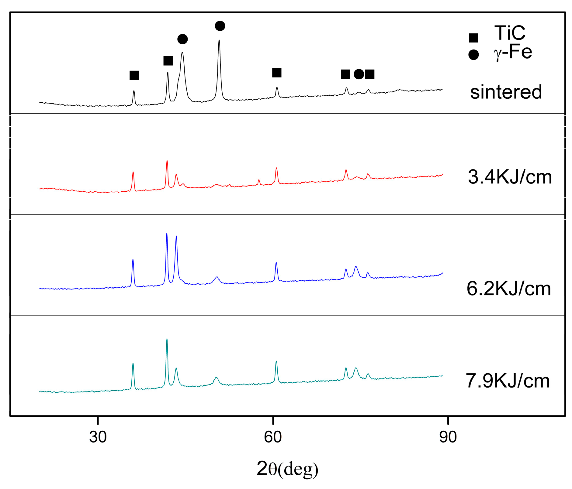
  • The microstructure of TiC cermet remains the same after welding thermo cycles, as all of the sintered sample and simulated samples contain TiC particles and austenite bonding phase. While the bonding phase of TiC cermet is strengthened due to alloy reinforcement and an increase in dislocation density, the tearing edges and dimples were increased, and the overall shear strength of the samples improved with the increase in heat input. However, TiC particles dissolve and embrittlement is obvious with the continuous increase in heat input, which leads to a decrease in the strength of the material.

Author Contributions

Conceptualization, W.W. and S.G.; methodology, W.W.; validation, W.W., S.G. and Z.H.; investigation, W.W.; writing—review and editing, W.W.; project administration, W.W. and H.Z. All authors have read and agreed to the published version of the manuscript.

Funding

This research received no external funding.

Institutional Review Board Statement

Not applicable.

Informed Consent Statement

Not applicable.

Data Availability Statement

Not applicable.

Acknowledgments

The authors are grateful to Jianjun Wei for giving them permission to pursue this research work.

Conflicts of Interest

The authors declare no conflict of interest.

References

  1. Namini, A.S.; Ahmadi, Z.; Babapoor, A.; Shokouhimehr, M.; Asl, M.S. Microstructure and thermomechanical characteristics of spark plasma sintered TiC ceramics doped with nano-sized WC. Ceram. Int. 2018, 45, 2153–2160. [Google Scholar] [CrossRef]
  2. Babapoor, A.; Asl, M.S.; Ahmadi, Z.; Namini, A.S. Effects of spark plasma sintering temperature on densification, hardness and thermal conductivity of titanium carbide. Ceram. Int. 2018, 44, 14541–14546. [Google Scholar] [CrossRef]
  3. Medveď, D.; Balko, J.; Sedlák, R.; Kovalčíková, A.; Shepa, I.; Naughton-Duszová, A.; Bączek, E.; Podsiadło, M.; Dusza, J. Wear resistance of ZrB2 based ceramic composites. Int. J. Refract. Met. Hard Mater. 2019, 81, 214–224. [Google Scholar] [CrossRef]
  4. Fattahi, M.; Vaferi, K.; Vajdi, M.; Moghanlou, F.S.; Namini, A.S.; Asl, M.S. Aluminum nitride as an alternative ceramic for fabrication of microchannel heat exchangers: A numerical study. Ceram. Int. 2020, 46, 11647–11657. [Google Scholar] [CrossRef]
  5. Fattahi, M.; Delbari, S.A.; Namini, A.S.; Ahmadi, Z.; Azadbeh, M.; Asl, M.S. Characterization of triplet Ti–TiB–TiC composites: Comparison of in-situ formation and ex-situ addition of TiC. Ceram. Int. 2020, 46, 11726–11734. [Google Scholar] [CrossRef]
  6. Nekahi, S.; Vaferi, K.; Vajdi, M.; Moghanlou, F.S.; Asl, M.S.; Shokouhimehr, M. A numerical approach to the heat transfer and thermal stress in a gas turbine stator blade made of HfB2. Ceram. Int. 2019, 45, 24060–24069. [Google Scholar] [CrossRef]
  7. Moghanlou, F.S.; Nekahi, S.; Vajdi, M.; Ahmadi, Z.; Motallebzadeh, A.; Shokouhimehr, A.; Shokouhimehr, M.; Jafargholinejad, S.; Asl, M.S. Effects of graphite nano-flakes on thermal and microstructural properties of TiB2–SiC composites. Ceram. Int. 2020, 46, 11622–11630. [Google Scholar] [CrossRef]
  8. Vafa, N.P.; Kakroudi, M.G.; Asl, M.S. Advantages and disadvantages of graphite addition on the characteristics of hot-pressed ZrB2–SiC composites. Ceram. Int. 2019, 46, 8561–8566. [Google Scholar] [CrossRef]
  9. Balak, Z.; Zakeri, M. Effect of HfB2 on microstructure and mechanical properties of ZrB2–SiC-based composites. Int. J. Refract. Met. Hard Mater. 2016, 54, 127–137. [Google Scholar] [CrossRef]
  10. Wang, Z.; Lin, T.; He, X.; Shao, H.; Tang, B.; Qu, X. Fabrication and properties of the TiC reinforced high-strength steel matrix composite. Int. J. Refract. Met. Hard Mater. 2016, 58, 14–21. [Google Scholar] [CrossRef]
  11. Moya, J.S.; Lopez-Esteban, S.; Pecharroman, C. The challenge of ceramic/metal microcomposites and nanocomposites. Prog. Mater. Sci. 2007, 52, 1017–1090. [Google Scholar] [CrossRef]
  12. Zhang, Y.; Feng, D.; He, Z.Y.; Chen, X.C. Progress in Joining Ceramics to Metals. J. Iron Steel Res. 2006, 13, 1–5. [Google Scholar] [CrossRef]
  13. Feng, J.; Zhang, L. Interface structure and mechanical properties of the brazed joint of TiC cermet and steel. J. Eur. Ceram. Soc. 2006, 26, 1287–1292. [Google Scholar] [CrossRef]
  14. Li, J.; Sheng, G.; Huang, L. Additional active metal Nb in Cu–Ni system filler metal for brazing of TiC cermet/steel. Mater. Lett. 2015, 156, 10–13. [Google Scholar] [CrossRef]
  15. Huang, L.; Sheng, G.M.; Li, J.; Huang, G.J.; Yuan, X.J. Partial Transient-liquid-phase Bonding of TiC Cermet to Stainless Steel Using Impulse Pressuring with Ti/Cu/Nb Interlayer. J. Cent. South Univ. 2018, 25, 1025–1032. [Google Scholar] [CrossRef]
  16. Kumar, S.; Sharma, A.; Pandey, C.; Basu, B.; Nath, S.K. Impact of Subsequent Pass Weld Thermal Cycles on First-Pass Coarse Grain Heat-Affected Zone’s Microstructure and Mechanical Properties of Naval Bainitic Steel. J. Mater. Eng. Perform. 2022, 31, 390–399. [Google Scholar] [CrossRef]
  17. Kumar, S.; Kasyap, P.; Pandey, C.; Basu, B.; Nath, S.K. Role of heat inputs on microstructure and mechanical properties in coarse-grained heat-affected zone of bainitic steel. CIRP J. Manuf. Sci. Technol. 2021, 35, 724–734. [Google Scholar] [CrossRef]
  18. Zhao, T.; Zheng, X.; Huang, D.; Zhu, Z.; Yin, Z. Thermodynamic Research on the Precipita-tion of Ti2O3, TiN and TiC in Continuous Casting of Titanium Microalloyed Steel. J. Physics. Conf. Ser. 2021, 2076, 012077. [Google Scholar] [CrossRef]
Figure 1. K-type thermocouples location.
Coatings 13 00476 g001
Figure 2. Thermal cycle of Gleeble simulation.
Coatings 13 00476 g002
Figure 3. SEM characterization with different heat input (a) sintered; (b) 3.4 KJ/cm; (c) 6.2 KJ/cm; (d) 7.9 KJ/cm. Spots 1–4 represent the EDS points.
Coatings 13 00476 g003
Figure 4. XRD patterns of TiC cermet.
Coatings 13 00476 g004
Figure 5. EBSD map for GND calculation with different heat input: (a) sintered; (b) 3.4 KJ/cm; (c) 6.2 KJ/cm; (d) 7.9 KJ/cm.
Coatings 13 00476 g005
Figure 6. Dislocation density.
Coatings 13 00476 g006
Figure 7. TEM micrographs with different heat input: (a) sintered; (b) 3.4 KJ/cm; (c) 6.2 KJ/cm; (d) 7.9 KJ/cm.
Coatings 13 00476 g007
Figure 8. Fracture section of TiC cermet with different heat input: (a) sintered; (b) 3.4 KJ/cm; (c) 6.2 KJ/cm; (d) 7.9 KJ/cm.
Coatings 13 00476 g008
Table 1. Chemical (wt.%) and mechanical properties of investigated samples.
TiCMnNiMoCFeShear Strength
(MPa)
Thermal Conductivity
(J/(gk))
39~416~6.31.7~1.81.3~1.40.45~0.6Bal.4690.524
Table 2. The simulation parameters.
Peak Temperature
(°C)
Heat Input
(KJ/cm)
Heating Rate
(°C/s)
Holding Time
(s)
Cooling Down Ratio
(°C/s)
12003.4500121.15
6.211.45
7.99.01
Table 3. EDS spot analysis of bonding phase (wt.%).
SpotCTiMnFeNi
19.120.6912.1574.23.84
29.560.710.8675.53.38
310.210.9210.4374.963.48
412.051.1910.2773.153.34
Table 4. Microhardness (HV0.01) of Bonding Phase and Shear strength (MPa) of the Specimens.
Heat Input (KJ/cm)Microhardness (HV0.01)Shear Strength (MPa)
0219.9469
3.4278.7684
6.2371.0584
7.9380.5566
Disclaimer/Publisher’s Note: The statements, opinions and data contained in all publications are solely those of the individual author(s) and contributor(s) and not of MDPI and/or the editor(s). MDPI and/or the editor(s) disclaim responsibility for any injury to people or property resulting from any ideas, methods, instructions or products referred to in the content.

