

Influence of Plasma Electrolytic Oxidation of Cast Al-Si Alloys on Their Phase Composition and Abrasive Wear Resistance

 ,
,  , ,
, , 
Abstract
1. Introduction
2. Materials and Methods
3. Results and Discussion
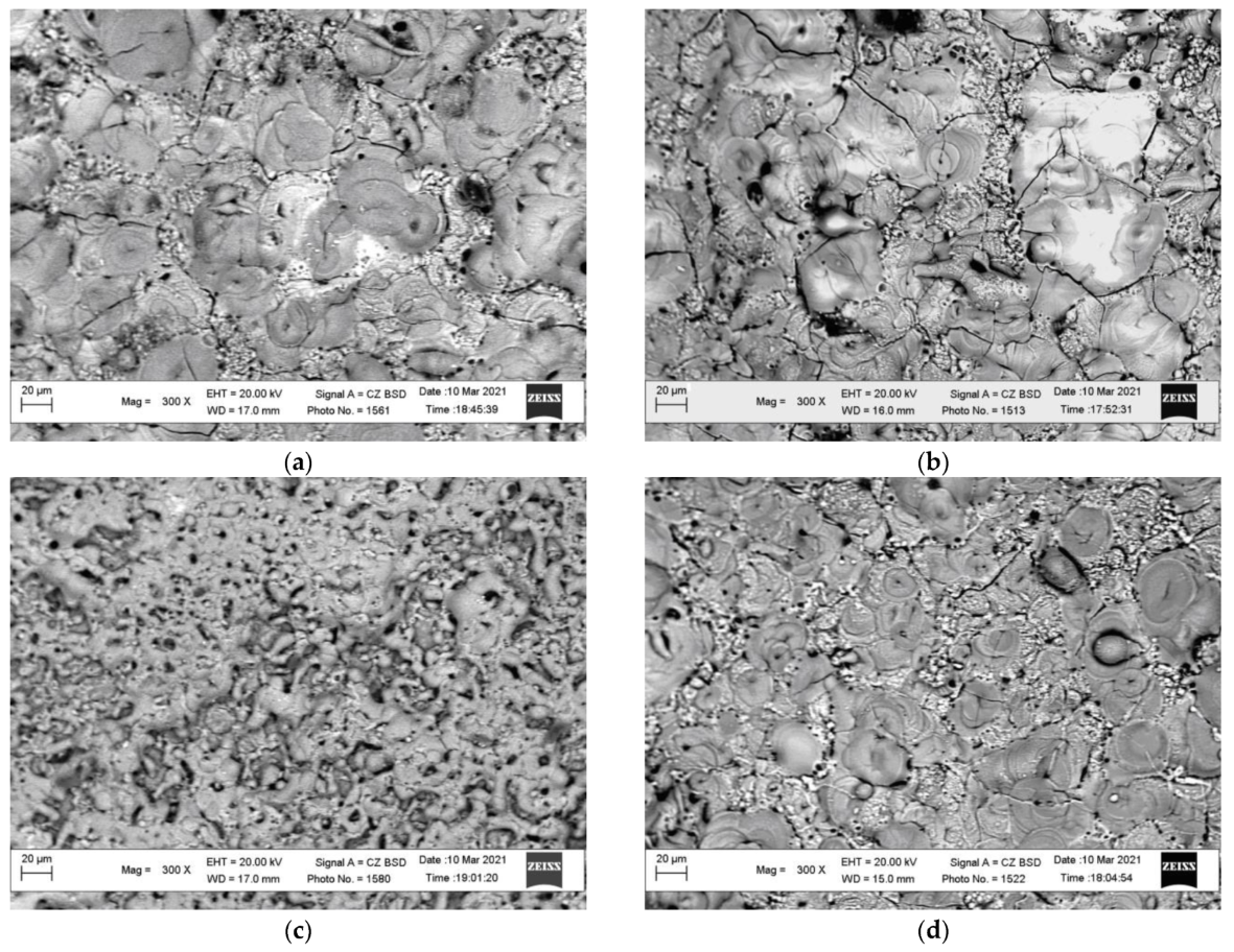
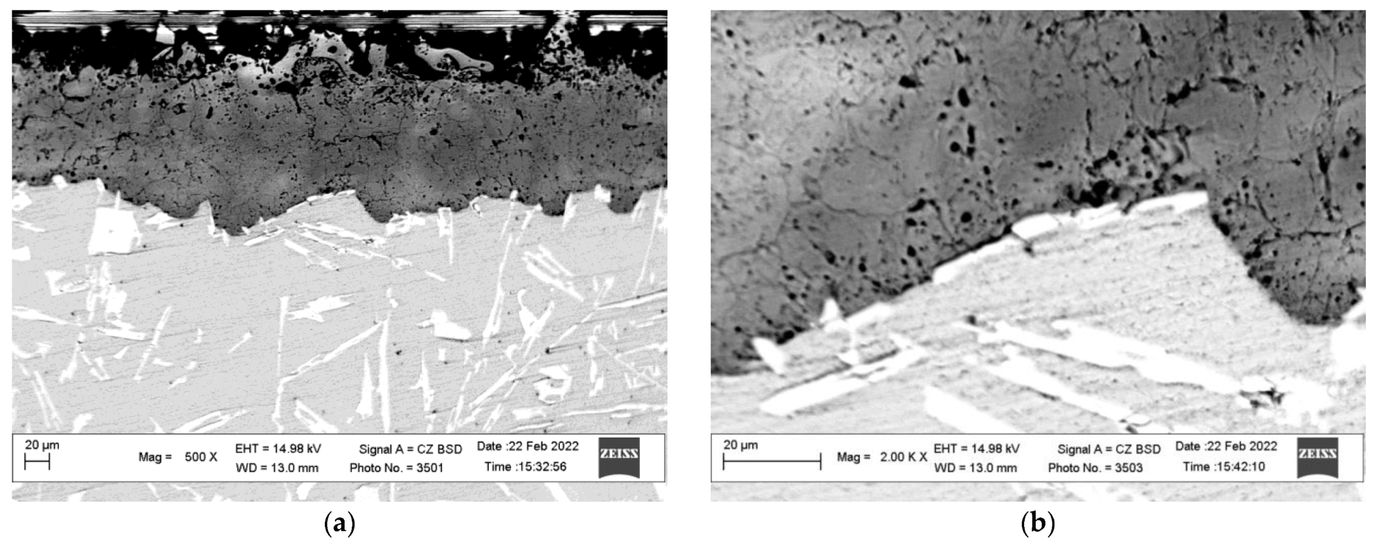
3.1. Morphology of the Surface of PEO Layers Synthesized on Cast Alloys AK9 and AK12 in Different Electrolytes
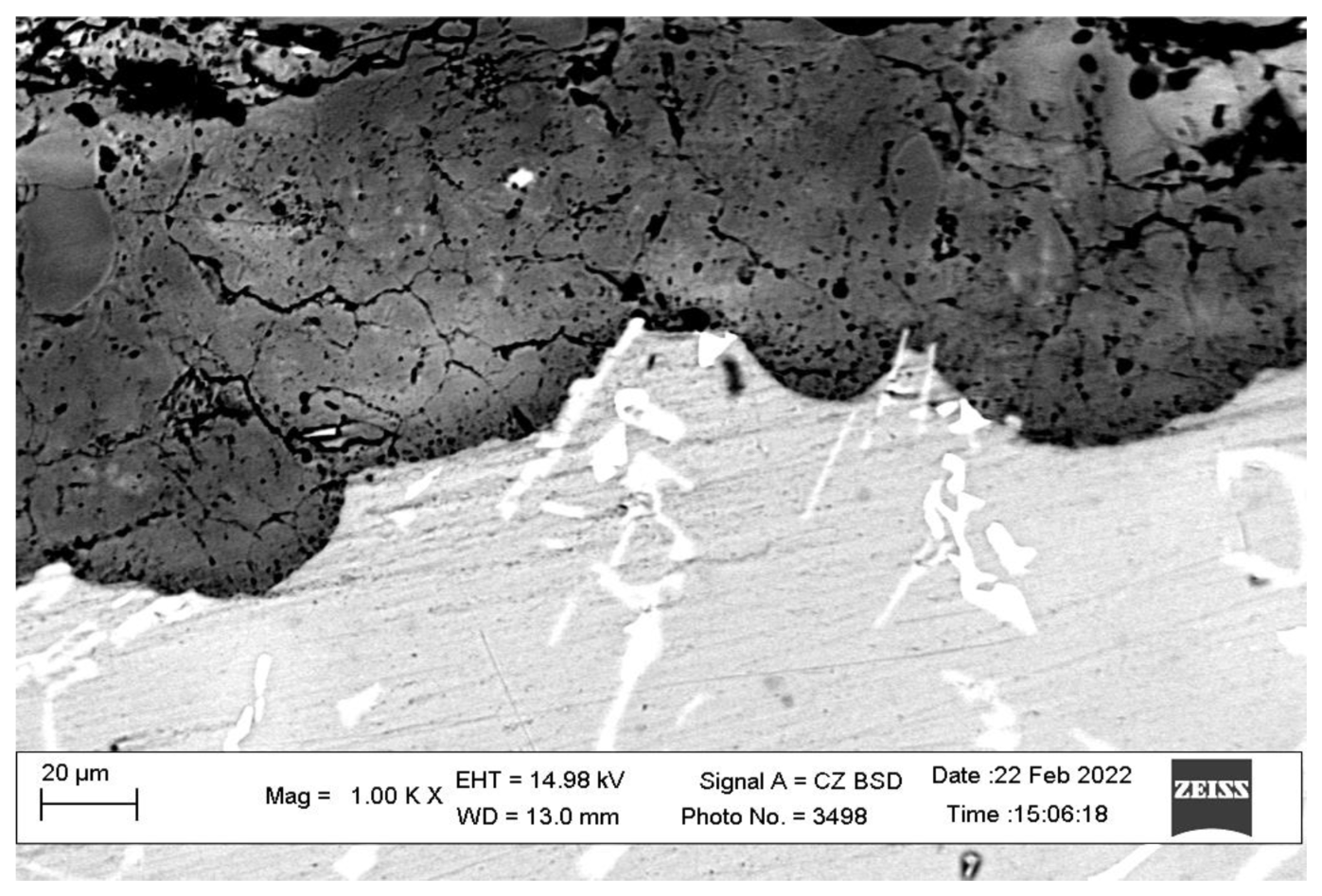
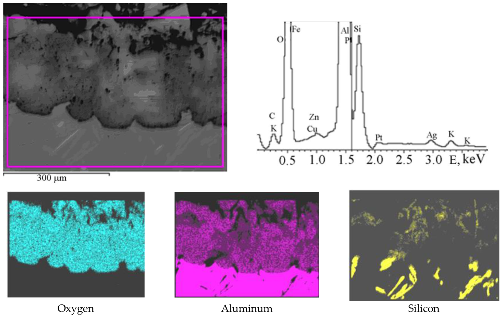
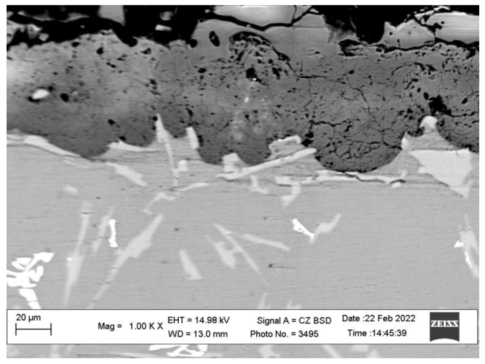
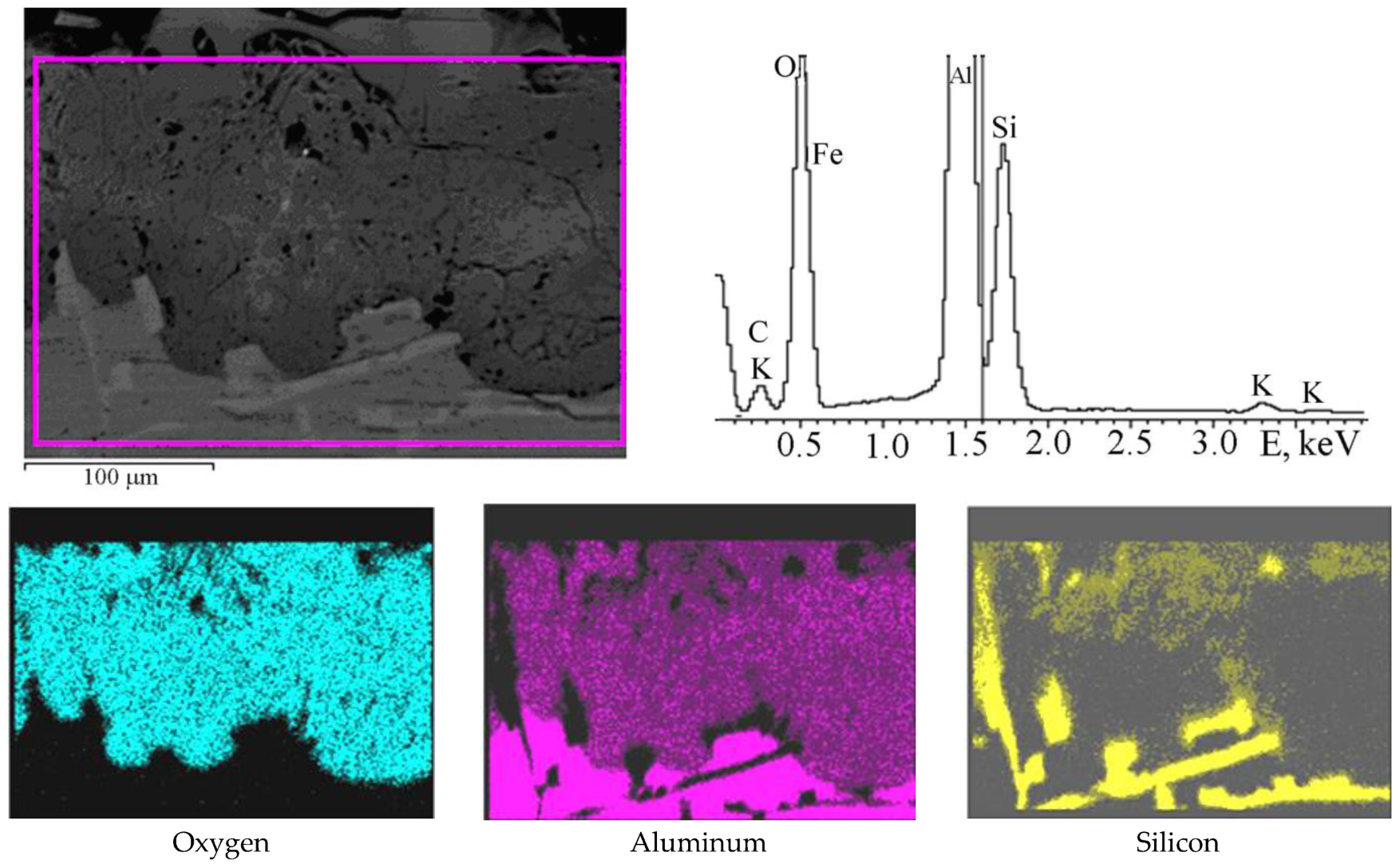
3.2. Comparison of AK9 and AK12 Alloys and PEO Layers Synthesized on Their Surfaces Using SEM-EDX Images
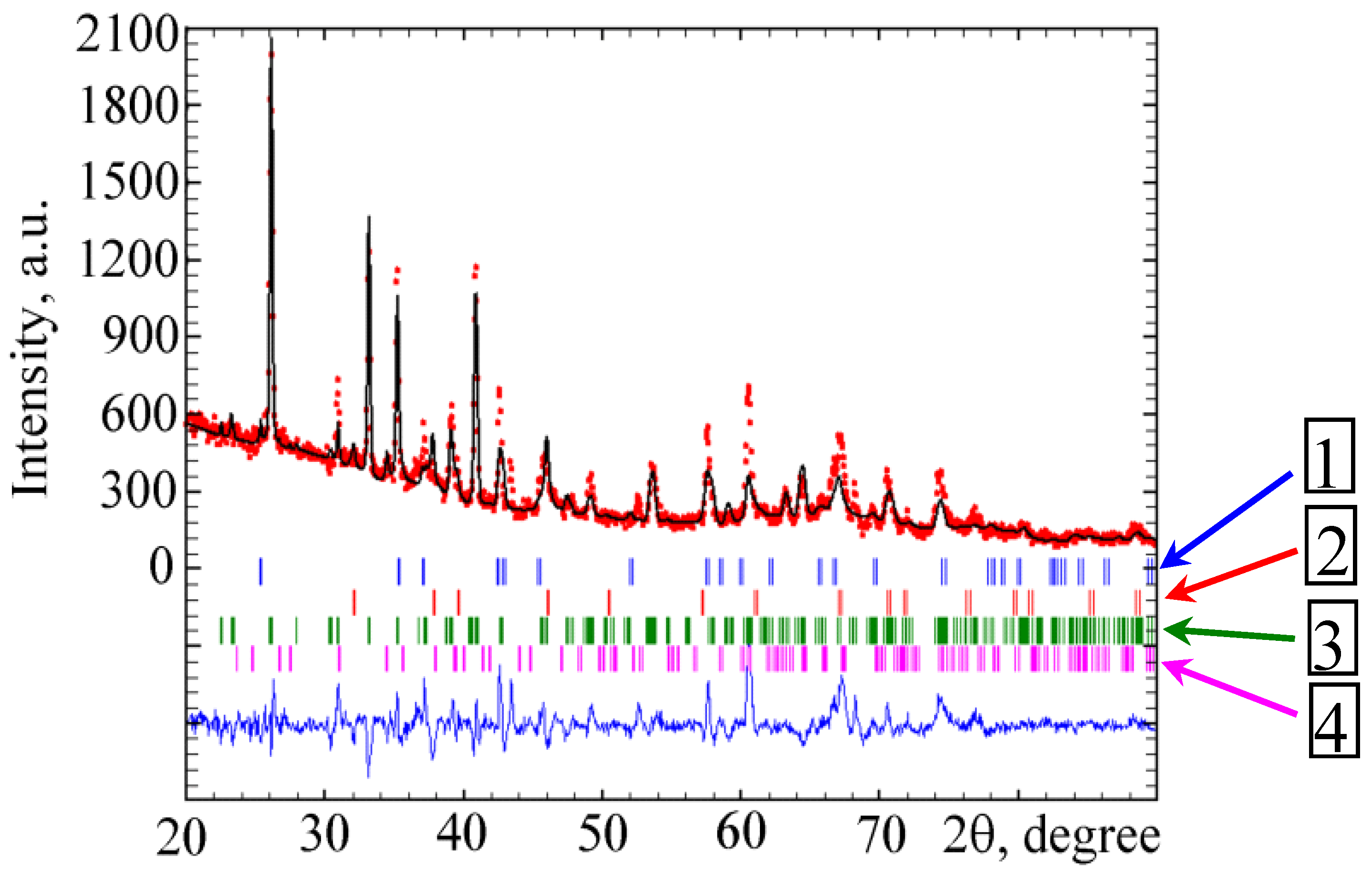
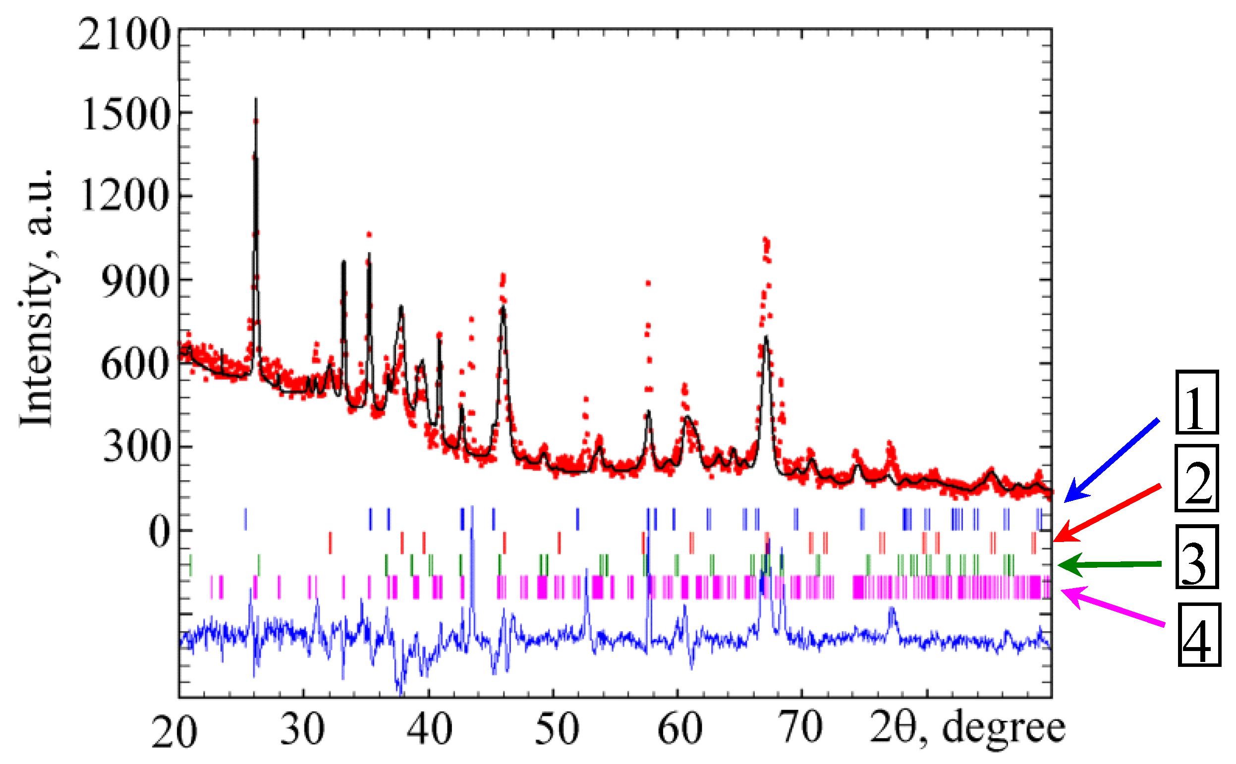
3.3. Structure and Phase Composition of the PEO Layer Synthesized in Different Electrolytes on AK9 Alloy
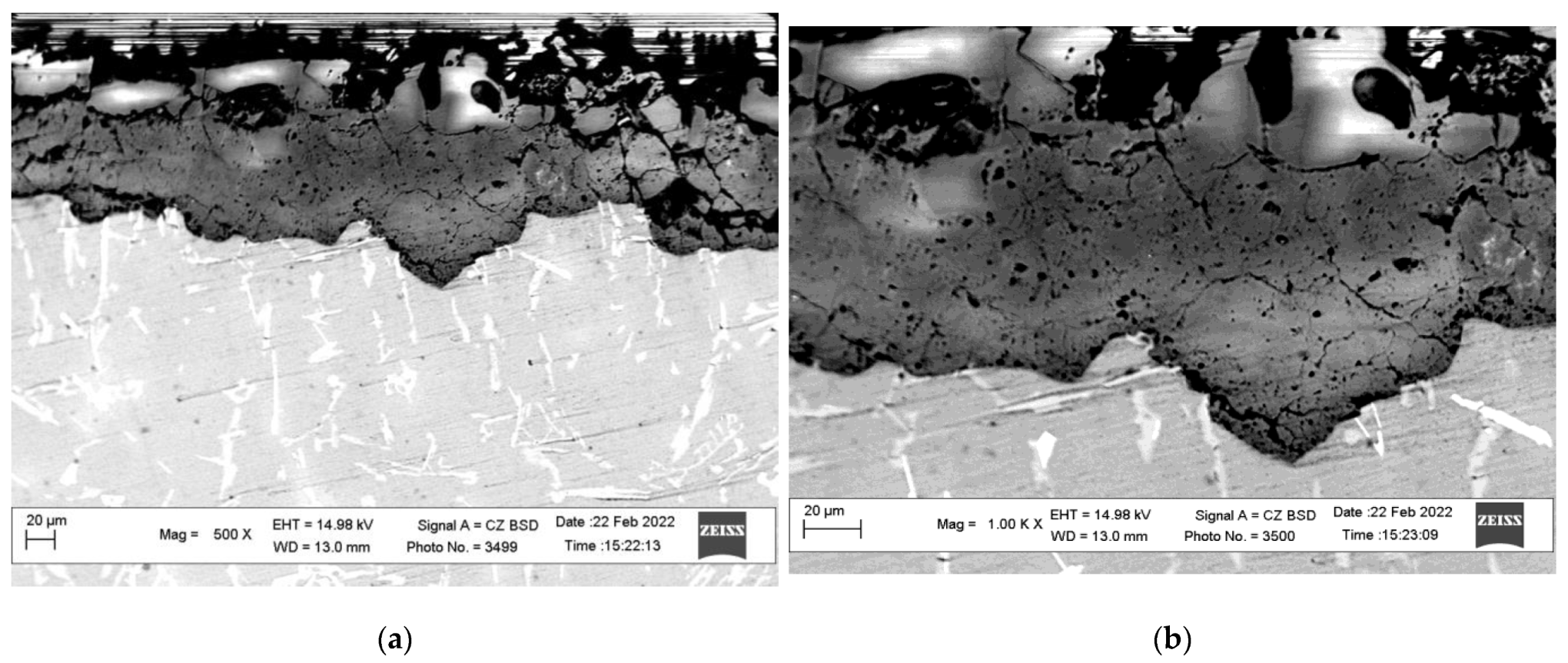
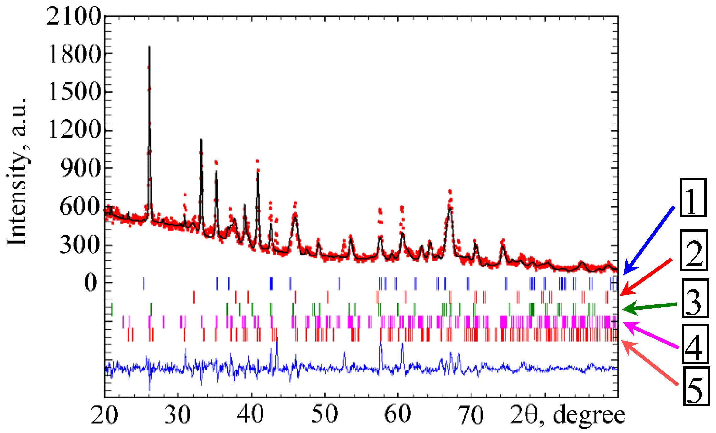
3.4. Structure and Phase Composition of PEO Layer Synthesized in Different Electrolytes on AK12 Alloy
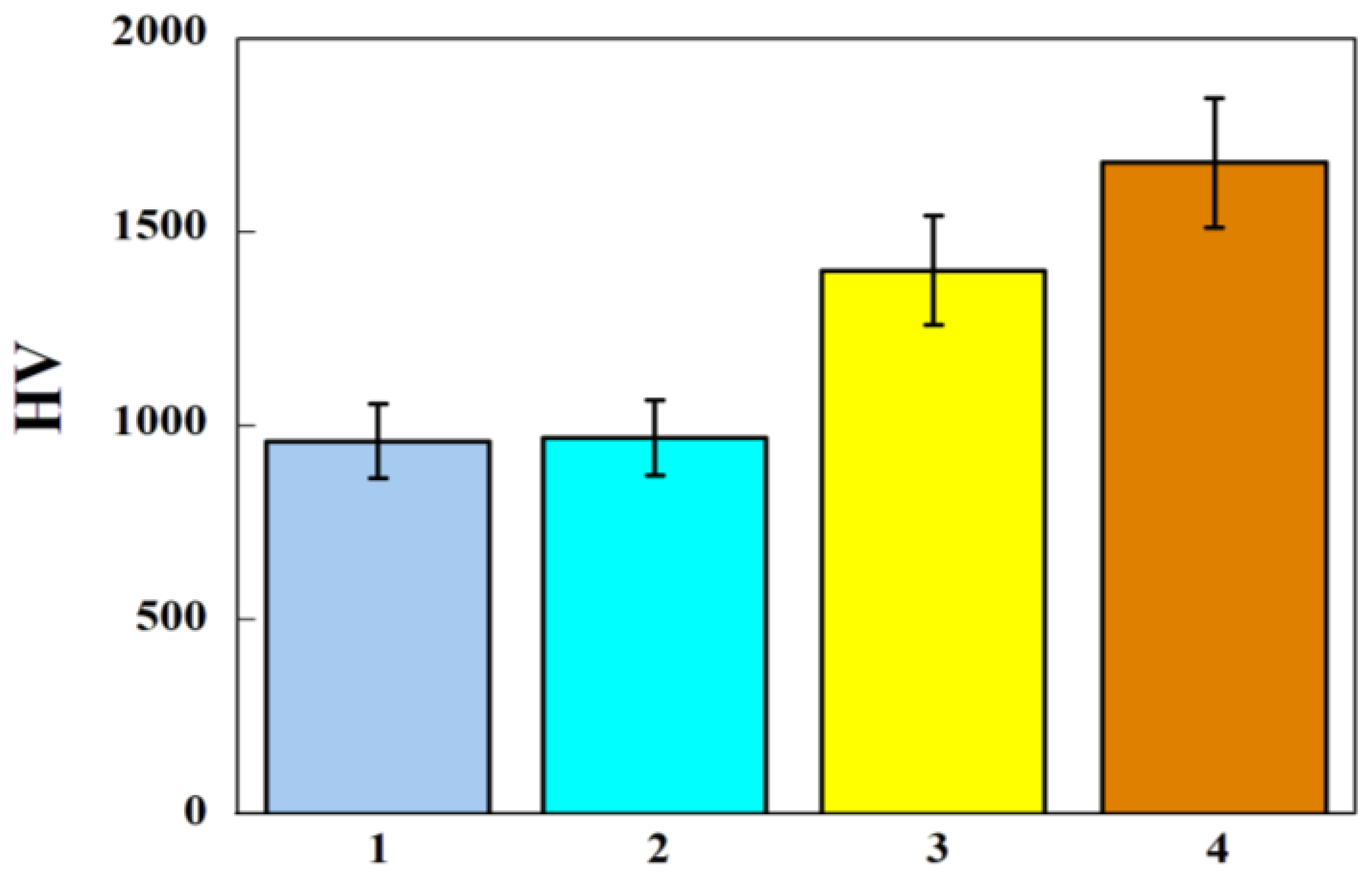
3.5. Microhardness of PEO Layers, Synthesized on Silumins
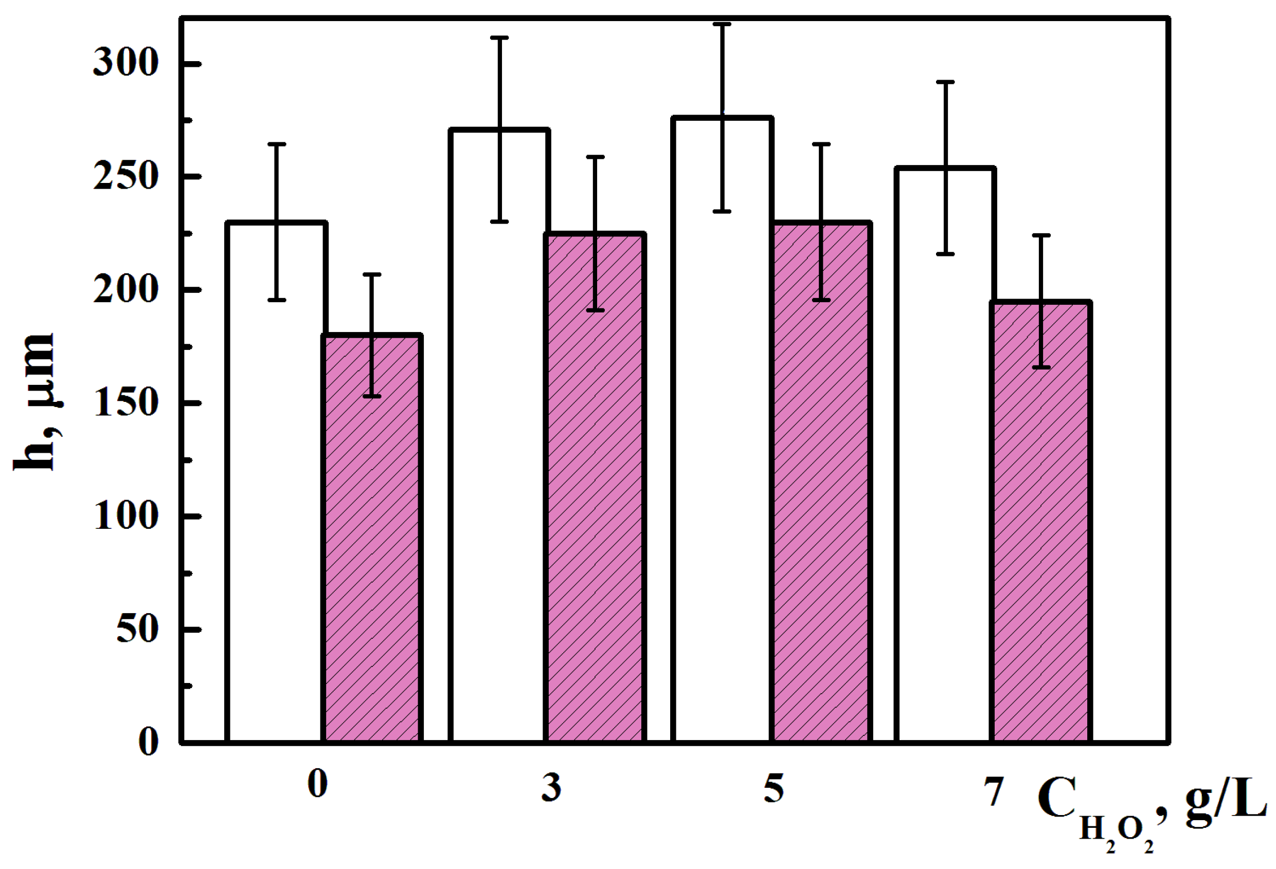
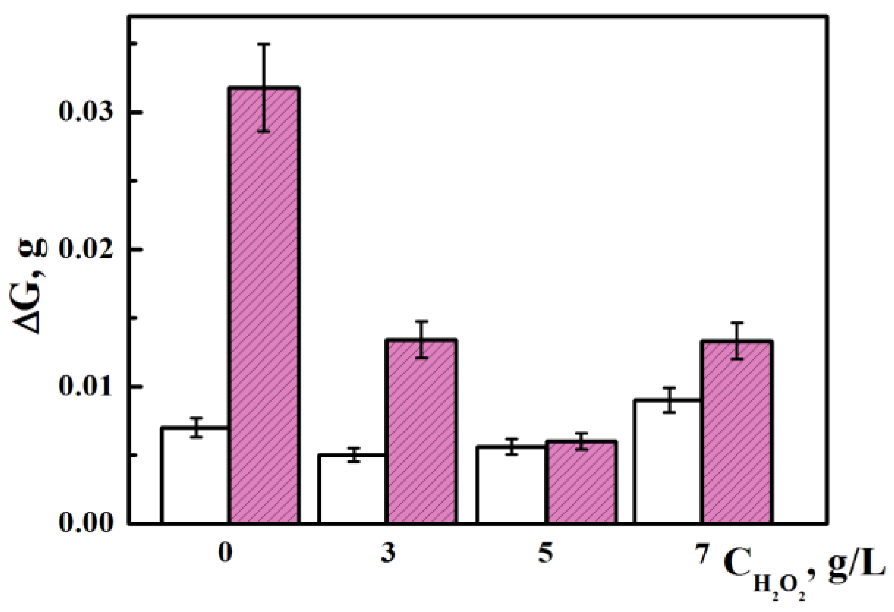
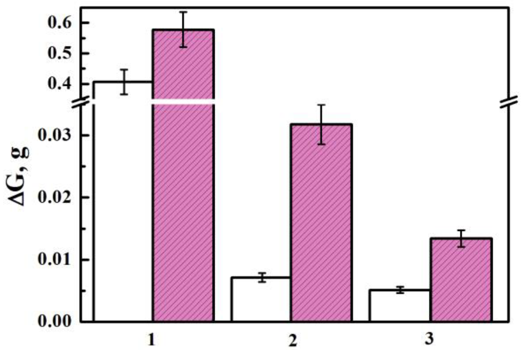
3.6. Abrasive Wear Resistance of PEO Layers, Synthesized on Silumins
4. Conclusions
Author Contributions
Funding
Institutional Review Board Statement
Informed Consent Statement
Data Availability Statement
Conflicts of Interest
References
- Vynar, V.А.; Pokhmurs’kyi, V.І.; Zin’, І.M.; Vasyliv, K.B.; Khlopyk, О.P. Determination of the mechanism of tribocorrosion of D16 alloy according to the electrode potential. Mater. Sci. 2018, 53, 717–723. [Google Scholar] [CrossRef]
- Nykyforchyn, H.; Kyryliv, V.; Maksymiv, O.; Kochubei, V.; Boyko, R.; Dovhunyk, V. Wear resistance of the surface nanocrystalline structure under an action of diethyleneglycol medium. Appl. Nanosci. 2019, 9, 1085–1090. [Google Scholar] [CrossRef]
- Pohrelyuk, I.M.; Fedirko, V.M.; Lavrys, S.M. Effect preminary ball burnishing in wear resistance of the nitreded VT22 alloy. J. Frict. Wear 2017, 38, 221–224. [Google Scholar] [CrossRef]
- Pohrelyuk, I.M.; Padgurskas, J.; Tkachuk, O.V.; Trush, V.S.; Lavrys, S.M. Influence of oxynitriding on antifriction properties of Ti–6Al–4V titanium Alloy. J. Frict. Wear 2020, 41, 333–337. [Google Scholar] [CrossRef]
- Abrahami, S.T.; de Kok, J.M.M.; Terryn, H.; Mol, J.M.C. Towards Cr(VI)-free anodization of aluminum alloys for aerospace adhesive bonding applications. Front. Chem. Sci. Eng. 2017, 11, 465–482. [Google Scholar] [CrossRef]
- Zeng, Z.; Zhang, J. Electrodeposition and tribological behavior of amorphous chromium-alumina composite coatings. Surf. Coat. Technol. 2008, 202, 2725–2730. [Google Scholar] [CrossRef]
- Ropyak, L.; Ostapovych, V. Optimization of process parameters of chrome plating for providing quality indicators of reciprocating pumps parts. East.-Eur. J. Enterp. Technol. 2016, 2, 50–62. [Google Scholar] [CrossRef]
- Torrescano Alvarez, J. Hard Anodic Films for Aluminium Alloys; The University of Manchester: Manchester, UK, 2018; p. 184. [Google Scholar]
- Student, M.M.; Pohrelyuk, J.M.; Hvozdetskyi, V.M.; Veselivska, H.H.; Zadorozhna, K.R.; Mardarevych, R.S.; Dzioba, Y.V. Influence of the composition of electrolyte for hard anodizing of aluminium on the characteristics of oxide layer. Mater. Sci. 2021, 57, 240–247. [Google Scholar] [CrossRef]
- Takata, N.; Kodaira, H.; Sekizawa, K.; Suzuki, A.; Kobashi, M. Change in the microstructure of selectively laser-melted AlSi10Mg alloy with heat treatments. Mat. Sci. Eng. A 2017, 704, 218–228. [Google Scholar] [CrossRef]
- Sušnik, J.; Šturm, R.; Grum, J. Influence of Laser Surface Remelting on Al-Si Alloy Properties. Stroj. Vestn.-J. Mech. Eng. 2012, 58, 614–620. [Google Scholar] [CrossRef]
- Tillová, E.; Ďuriníková, E.; Chalupová, M.; Radek, N. Effect of laser surface treatment on the quality of microstructure in recycled Al-Zn-Si cast alloy. Prod. Eng. Arch. 2014, 2, 26–32. [Google Scholar] [CrossRef]
- Gawdzińska, K.; Bryll, K.; Nagolska, D. Influence of heat treatment of abrasive wear resistance of silumin matrix composite casting. Arch. Met. Mater. 2016, 61, 177–182. [Google Scholar] [CrossRef]
- Zaguliaev, D.; Konovalov, S.; Ivanov, Y.; Gromov, V.; Petrikova, E. Microstructure and mechanical properties of dopedand electron-beam treated surface of hypereutectic Al-11.1%Si alloy. J. Mater. Res. Technol. 2019, 8, 3835–3842. [Google Scholar] [CrossRef]
- Yerokhin, A.L.; Nie, X.; Leyland, A.; Matthews, A.; Dowey, S.J. Plasma electrolysis for surface engineering. Surf. Coat. Technol. 1999, 122, 73–93. [Google Scholar] [CrossRef]
- Nykyforchyn, H.M.; Agarwala, V.S.; Klapkiv, M.D.; Posuvailo, V.M. Simultaneous reduction of wear and corrosion of titanium, magnesium and zirconium alloys by surface plasma electrolytic oxidation treatment. Adv. Mat. Res. 2008, 38, 27–35. [Google Scholar] [CrossRef]
- Liu, W.; Pu, Y.; Liao, H.; Lin, Y.; He, W. Corrosion and wear behavior of PEO coatings on D16T aluminum alloy with different concentrations of graphene. Coatings 2020, 10, 249. [Google Scholar] [CrossRef]
- Hussein, R.O.; Nie, X.; Northwood, D.O. An investigation of ceramic coating growth mechanisms in plasma electrolytic oxidation (PEO) processing. Electrochim. Acta. 2013, 112, 111–119. [Google Scholar] [CrossRef]
- Gutsalenko, Y.G.; Sevidova, E.K.; Stepanova, I.I. Evaluetion of technological capability to form dielectric coatings on AK6 alloy, using method of microarc oxidation. Surf. Eng. Appl. Electrochem. 2019, 55, 602–606. [Google Scholar] [CrossRef]
- Saberi, A.; Bakhsheshi-Rad, H.R.; Abazari, S.; Ismail, A.F.; Sharif, S.; Ramakrishna, S.; Daroonparvar, M.; Berto, F. A Comprehensive review on surface modifications of biodegradable magnesium-based implant alloy: Polymer coatings opportunities and challenges. Coatings 2021, 11, 747. [Google Scholar] [CrossRef]
- Bakhtiari-Zamani, H.; Saebnoori, E.; Bakhsheshi-Rad, H.R.; Berto, F. Corrosion and wear behavior of TiO2/TiN duplex coatings on titanium by plasma electrolytic oxidation and gas nitriding. Materials 2022, 15, 8300. [Google Scholar] [CrossRef]
- Schneider, H.; Fischer, R.X.; Voll, D. Mullite with lattice constants a > b. J. Am. Ceram. Soc. 1993, 76, 1879–1881. [Google Scholar] [CrossRef]
- Schneider, H.; Schreuer, J.; Hildman, B. Structure and properties of mullite—A review. J. Eur. Ceram. Soc. 2008, 28, 329–344. [Google Scholar] [CrossRef]
- Burnharn, C.W. Refinement of crystal structure of sillimanite. Z. Für Krist.-Cryst. Mater. 1963, 118, 127–148. [Google Scholar] [CrossRef]
- Rodríguez-Carvajal, J. Program FullProf.2k; Version 2.20; Laboratoire Léon Brillouin (CEA–CNRS): Saclay, France, 2002. [Google Scholar]
- Hutsaylyuk, V.; Student, M.; Dovhunyk, V.; Posuvailo, V.; Student, O.; Koval’chuk, I. Effect of hydrogen on the wear resistance of steel upon contact with plasma electrolytic oxidation layers synthesized on aluminum alloys. Metals 2019, 9, 280. [Google Scholar] [CrossRef]
- NIST-JANAF Tables. Available online: https://janaf.nist.gov/periodic_table.html (accessed on 1 December 2022).
- Hutsaylyuk, V.; Student, M.; Posuvailo, V.; Student, O.; Maruchak, P.; Zakiev, V. The role of hydrogen in the formation of oxide-ceramic layers on aluminum alloys during their plasma-electrolytic oxidation. J. Mater. Res. Technol. 2021, 14, 1682–1696. [Google Scholar] [CrossRef]
- Logvinkov, S.M. Solid-Phase Exchange Reactions in Ceramic Technology: Monograph; KhNEU: Kharkiv, Ukraine, 2013; p. 248. (In Russian) [Google Scholar]
- Student, M.M.; Dovhunyk, V.M.; Posuvailo, V.M.; Koval’chuk, I.V.; Hvozdets’kyi, V.M. Friction behavior of iron-carbon alloys in couples with plasma-electrolytic oxide-ceramic layers synthesized on D16T alloy. Mater. Sci. 2017, 53, 359–367. [Google Scholar] [CrossRef]
- Posuvailo, V.M.; Kulyk, V.V.; Duriagina, Z.A.; Koval’chuck, I.V.; Student, M.M.; Vasyliv, B.D. The effect of electrolyte composition on the plasma electrolyte oxidation and phase composition of oxide ceramic coatings formed on 2024 aluminium alloy. Arch. Mat. Scie. Eng. 2020, 105, 49–55. [Google Scholar] [CrossRef]
- Martin, J.; Leone, P.; Nominé, A.; Veys-Renaux, D.; Henrion, G.; Belmonte, T. Influence of electrolyte ageing on the plasma electrolytic oxidation of aluminium. Surf. Coat. Technol. 2015, 269, 36–46. [Google Scholar] [CrossRef]
- Rogov, A.; Lyu, H.; Matthews, A.; Yerokhin, A. Plasma electrolytic oxidation of additively manufactured and cast AlSi12 alloys. Surf. Coat. Technol. 2020, 399, 126116. [Google Scholar] [CrossRef]
- Borgardt, E.D.; Katsman, A.V.; Krishtal, M.M. Effect of TiN particles on mechanical and anticorrosive properties of oxide layers formed by PEO on silumin. In Journal of Physics: Conference Series; IOP Publishing: Bristol, UK, 2021. [Google Scholar] [CrossRef]
- Li, G.; Ma, F.; Li, Z.; Xu, Y.; Gao, F.; Guo, L.; Zhu, J.; Li, G.; Xia, Y. Influence of applied frequency on thermal physical properties of coatings prepared on Al and AlSi alloys by plasma electrolytic oxidation. Coatings 2021, 11, 1439. [Google Scholar] [CrossRef]
- Moshrefifar, M.; Ebrahimifar, H.; Hakimizad, A. Systematic Investigation of Silicon Content Effects on the PEO Coatings’ Properties on Al–Si Binary Alloys in Silicate-Based and Tungstate-Containing Electrolytes. Coatings 2022, 12, 1438. [Google Scholar] [CrossRef]
- Gabor, R.; Prymus, T.; Cvrček, L.; Nehasil, V.; Hlinka, J.; Buřil, M.; Tokarčíkova, M.; Seidlerová, J. Final surface modification for better wear resistance of ceramic coating on cast AlSi10Mg alloy. Ceram. Int. 2022, 48, 37433–3744715. [Google Scholar] [CrossRef]
- Polunin, A.V.; Cheretaeva, A.O.; Borgardt, E.D.; Rastegaev, I.A.; Krishtal, M.M.; Katsman, A.V.; Yasnikov, I.S. Improvement of oxide layers formed by plasma electrolytic oxidation on cast Al-Si alloy by incorporating TiC nanoparticles. Surf. Coat. Technol. 2021, 423, 127603. [Google Scholar] [CrossRef]


| Phase | a, Å | b, Å | c, Å | PG | wt% |
|---|---|---|---|---|---|
| α-Al2O3 | 4.889 (8) | 4.889 (8) | 12.71 (2) | R-3C | 10 |
| γ-Al2O3 | 7.893 (2) | 7.893 (2) | 7.893 (2) | Fd-3m | 25 |
| SiO2 | 5.006 (6) | 5.006 (6) | 5.505 (2) | P3121 | 5 |
| Al2O3·SiO2 | 7.610 (9) | 7.665 (4) | 5.781 (2) | Pbnm | 60 |
| Phase | a, Å | b, Å | c, Å | S.G. | wt% |
|---|---|---|---|---|---|
| α-Al2O3 | 4.749 (9) | 4.749 (9) | 12.969 (3) | R-3C | 10 |
| γ-Al2O3 | 7.896 (3) | 7.896 (3) | 7.896 (3) | Fd-3m | 40 |
| SiO2 | 5.006 (6) | 5.006 (6) | 5.505 (2) | P3121 | 10 |
| Al2O3·SiO2 | 7.610 (9) | 7.665 (4) | 5.781 (2) | Pbnm | 40 |
| Phase | a, Å | b, Å | c, Å | S.G. | wt% |
|---|---|---|---|---|---|
| α-Al2O3 | 4.893 (5) | 4.893 (5) | 12.653 (1) | R-3C | 6 |
| γ-Al2O3 | 7.877 (4) | 7.877 (4) | 7.877 (4) | Fd-3m | 25 |
| SiO2 | 4.881 (2) | 4.881 (2) | 5.700 (1) | P3121 | 4 |
| Al2O3·SiO2 | 7.610 (9) | 7.665 (4) | 5.781 (2) | Pbnm | 65 |
| Phase | a, Å | b, Å | c, Å | S.G. | wt% |
|---|---|---|---|---|---|
| α-Al2O3 | 4.884 (5) | 4.884 (5) | 12.72 (1) | R-3C | 10 |
| γ-Al2O3 | 7.894 (9) | 7.894 (9) | 7.894 (9) | Fd-3m | 35 |
| SiO2 | 4.885 (2) | 4.885 (2) | 5.700 (7) | P3121 | 20 |
| Al2O3·SiO2 | 7.610 (9) | 7.665 (4) | 5.781 (2) | Pbnm | 32 |
| 3Al2O3·2SiO2 | 7.531 (1) | 7.208 (2) | 2.888 (9) | Pbam | 3 |
Disclaimer/Publisher’s Note: The statements, opinions and data contained in all publications are solely those of the individual author(s) and contributor(s) and not of MDPI and/or the editor(s). MDPI and/or the editor(s) disclaim responsibility for any injury to people or property resulting from any ideas, methods, instructions or products referred to in the content. |
© 2023 by the authors. Licensee MDPI, Basel, Switzerland. This article is an open access article distributed under the terms and conditions of the Creative Commons Attribution (CC BY) license (https://creativecommons.org/licenses/by/4.0/).
Share and Cite
Student, M.; Pohrelyuk, I.; Padgurskas, J.; Posuvailo, V.; Hvozdets’kyi, V.; Zadorozhna, K.; Chumalo, H.; Veselivska, H.; Kovalchuk, I.; Kychma, A. Influence of Plasma Electrolytic Oxidation of Cast Al-Si Alloys on Their Phase Composition and Abrasive Wear Resistance. Coatings 2023, 13, 637. https://doi.org/10.3390/coatings13030637
Student M, Pohrelyuk I, Padgurskas J, Posuvailo V, Hvozdets’kyi V, Zadorozhna K, Chumalo H, Veselivska H, Kovalchuk I, Kychma A. Influence of Plasma Electrolytic Oxidation of Cast Al-Si Alloys on Their Phase Composition and Abrasive Wear Resistance. Coatings. 2023; 13(3):637. https://doi.org/10.3390/coatings13030637
Chicago/Turabian StyleStudent, Mykhailo, Iryna Pohrelyuk, Juozas Padgurskas, Volodymyr Posuvailo, Volodymyr Hvozdets’kyi, Khrystyna Zadorozhna, Halyna Chumalo, Halyna Veselivska, Ihor Kovalchuk, and Andrii Kychma. 2023. "Influence of Plasma Electrolytic Oxidation of Cast Al-Si Alloys on Their Phase Composition and Abrasive Wear Resistance" Coatings 13, no. 3: 637. https://doi.org/10.3390/coatings13030637
APA StyleStudent, M., Pohrelyuk, I., Padgurskas, J., Posuvailo, V., Hvozdets’kyi, V., Zadorozhna, K., Chumalo, H., Veselivska, H., Kovalchuk, I., & Kychma, A. (2023). Influence of Plasma Electrolytic Oxidation of Cast Al-Si Alloys on Their Phase Composition and Abrasive Wear Resistance. Coatings, 13(3), 637. https://doi.org/10.3390/coatings13030637