Abstract
Dry hard turning (DHT) provides an effective process for finishing high-hardness materials. Machining-induced surface integrity has a direct impact on functional performance. This study compares the effects of the DHT and grinding processes on machining-induced surface integrity and fatigue performance of 18CrNiMo7-6 steel. The DHT and grinding experiment were carried out by using a polycrystalline cubic boron nitride tool and corundum wheel, respectively. The 3D surface morphology, surface roughness, surface residual stress, and machining accuracy of the hourglass-shaped specimen were measured. The fatigue fracture was characterized by scanning electron microscopy. The experimental results show that compared to grinding, DHT has obtained a larger surface compressive residual stress (the maximum axial and tangent residual stresses are −762.6 MPa and −442.8 MPa, respectively) and a lower surface roughness (the minimum Ra and Rq are 0.172 μm and 0.230 μm, respectively). This study is an attempt to use DHT instead of a grinding process to finish 18CrNiMo7-6 steel, providing a reference for high-quality and sustainable manufacturing of hardened steel.
1. Introduction
Dry hard turning (DHT) technology is widely used to process materials with a hardness above 45 HRC [1,2,3]. When the DHT process is applied in the finishing operation, a high cutting speed and large depth of cut are generally used to remove materials, and ideal machining quality and accuracy are also obtained [3]. Due to their high hardness and low iron affinity, cubic boron nitride (cBN), polycrystalline cubic boron nitride (PcBN), and ceramic tools are frequently used for DHT-hardened steel [4,5]. Before the emergence of DHT technology, the finishing operation of hardened steel was generally completed by a grinding process. Under certain circumstances, DHT has advantages over grinding in process flexibility and sustainability [4,5,6]. On the one hand, the grinding process has restrictions on the workpiece with a special shape, and the grinding wheel should be trimmed according to the shape of the components. On the other hand, compared with grinding, DHT has a higher material removal rate and a higher surface residual compressive stress [1]. The application of ultrahard tools is conducive to achieving sustainable manufacturing while saving on cutting fluid costs.
Surface integrity has a significant impact on the functional performance (including fatigue performance) of components [7,8,9,10]. Meanwhile, the application of DHT to improve the surface integrity of hardened steel components in the finishing process has been widely studied by academic and industrial circles [11,12]. Tang et al. [13] carried out the finishing operation of AISI D2 hardened steel by using the DHT process, and the experimental results showed that the minimum surface roughness Ra is 0.34 μm when the tool corner radius is 0.8 mm, which can achieve the surface finish of the grinding process. Holubjak et al. [14] found that when the cutting speed of DHT high carbon steel is 100 m/min, the axial surface residual stress is up to −850 MPa. Kundrak et al. [15] compared DHT and grinding processes and found that the surface roughness obtained by the two processes was not much different, and the former had advantages in some surface integrity characteristics. Martell et al. [16] analyzed the surface residual stress of DHT and grinding AISI 1053 hardened steel; the DHT process obtained higher surface compressive residual stress in the cutting direction. Asutosh et al. [17] established the surface roughness model of the DHT process and pointed out that the tool corner radius and feed rate are the main factors affecting the surface roughness. Sarnobat et al. [18] analyzed the influence of tool edge geometry and cutting parameters on surface residual stress and roughness during the DHT process; the optimal cutting parameter range is obtained for residual stress optimization. Smith [19] carried out the DHT process of AISI 52100 hardened steel and found that tool flank wear directly affected surface residual stress. Umbrello et al. [20] found that optimizing cutting parameters and tool geometry parameters is beneficial to improving the distribution of residual stress. It is generally believed that a reduction in surface roughness and an increase in surface compressive residual stress are beneficial to improve the fatigue performance [21,22,23].
18CrNiMo7-6 steel is widely used in aviation, automobile, electric power, and other industrial fields [24,25]. The technologies for the surface-strengthening treatment of 18CrNiMo7-6 steel include carburizing [26,27,28], shot peening [29,30], waterjet peening, surface rolling, etc. These surface-strengthening treatment methods can induce microstructural changes, produce compressive residual stress, and improve fatigue properties. Springer et al. [25] studied the effect of dynamic recrystallization and phase transformation on the microstructure of 18CrNiMo7-6 steel. The results show that the softening effect shown by the stress–strain curve is caused by the recrystallization of austenite.
The surface modification layer of 18CrNiMo7-6 steel was formed after carburizing heat treatment. The physical properties of the surface modification layer have a gradient change along the depth direction, which has attracted the attention of many scholars. Wang et al. [26] investigated the influence of residual stress and microstructure caused by carburizing heat treatment on the corrosion resistance of 18CrNiMo7-6 steel. The results show that with the increase in the depth of the carburized layer, the residual compressive stress in the carburized layer increases at first and then decreases and reaches stability in the matrix material. Electrochemical tests showed that the electrochemical impedance and electrochemical potential increased with the reduction in residual compressive stress. Zhao et al. [27] proposed and verified a method for measuring the elastic modulus of the surface modification layer using a micro-pressure instrument. The elastic modulus and hardness of the surface modification layer of 18CrNiMo7-6 steel after carburizing heat treatment in different test directions under different loads and different indentations were studied. The results show that carburizing heat treatment can hardly change the elastic modulus of the surface modification layer of 18CrNiMo7-6 steel along the depth. They also obtained the empirical formula for the gradient hardness of the surface metamorphic layer in top and cross-section tests, which can be used to evaluate the hardness of different depths. At the same time, the elastic modulus and hardness obtained on the cross-section are higher than those on the top surface. Zhang et al. [28] systematically studied the effect of the microstructure of 18CrNiMo7-6 steel on its crack propagation path by using electron backscatter diffraction and scanning electron microscopy techniques; The results showed that the prior austenite grain boundary and martensite boundary hindered the crack growth. The crack growth path is affected by the microstructure of flat needles martensite, original austenite grain boundary, and crystal orientation. Ho et al. [29] studied the potential relationship between surface integrity caused by the shot peening process and fatigue life. The effect of shot peening parameters on the fatigue life of 18CrNiMo7-6 steel was evaluated by characterizing the surface integrity and carrying out relevant fatigue tests. The experimental results show that using large-diameter pellets followed by using small-diameter pellets is an effective method to improve surface integrity and fatigue performance.
To the best of the authors’ knowledge, few studies have directly compared the effects of DHT and grinding on the surface integrity and functional performance of 18CrNiMo7-6 steel. Although the DHT process has been widely used in the finishing of high-strength steel, the feasibility of DHT 18CrNiMo7-6 steel after carburizing heat treatment (~60 HRC) has not been studied.
In this study, the DHT and grinding processes of 18CrNiMo7-6 steel are compared. The objectives of this study are as follows: (1) explore the feasibility of using DHT to process 18CrNiMo7-6 steel; (2) optimize the cutting parameters during finishing 18CrNiMo7-6 steel; and (3) analyze the influence of surface integrity on fatigue performance. Section 2 introduces the material and dimensions, processing parameters, and characterization evaluation of fatigue specimens; Section 3 introduces the corresponding surface integrity and fatigue performance results; and Section 4 summarizes the overall performance of the DHT process. This study is an attempt to replace grinding with the DHT process, which provides the potential for high-quality and sustainable manufacturing.
2. Experimental Procedures
2.1. Materials
Before carburizing heat treatment, the 18CrNiMo7-6 steel sample is pre-shaped. The material was kept at 880 °C with 1.1 and 0.9% carbon potential for 3 and 1 h, respectively, after which it was tempered at 650 °C for 4 h. Then quenched at 835 °C for 2.25 h and deep cooled at −60 °C for 2 h, and finally tempered at 180 °C for 12 h. The carburized layer depth of the specimen is 0.70–0.80 mm, the surface hardness is ~58–63 HRC, and the center of the specimen retains sufficient plasticity and toughness. The composition of the 18CrNiMo7-6 steel after carburizing heat treatment is shown in Table 1.

Table 1.
Chemical composition of 18CrNiMo7-6 steel after carburizing heat treatment (wt%).
International Organization for Standardization divides the shapes of rotating bar bending fatigue specimens into cylindrical, tapered, and hourglass-shaped [31]. The hourglass-shaped specimen is selected in this study, and its dimensions are shown in Figure 1.
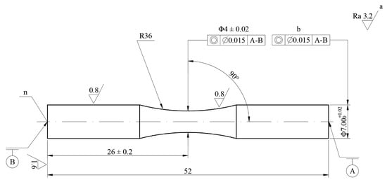
Figure 1.
Dimensions of the hourglass-shaped specimen (unit: mm). (Key, n: specimen number, a: others, b: two tops, A and B: datum, Ra: surface roughness, Φ: diameter).
2.2. Dry Hard Turning (DHT) Process
The DHT experiment was executed on a CAK4085 (Shenyang, Liaoning, China) computer numerical control (CNC) lathe. The PcBN cutting tool (BN-H10 VNGA160412-2S) was selected for the DHT process. The geometric parameters of the cutting tool are a rake angle of 0°, a cutting edge angle of 72.5°, and a clearance angle of 0°. The model of the tool holder is MVVNN2020K16. The schematic diagram and cutting parameters of the DHT process are shown in Figure 2 and Table 2, respectively. For each turning experiment, a new cutting tool was applied.
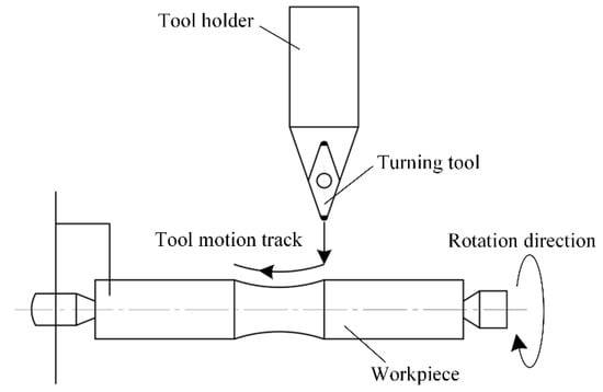
Figure 2.
Schematic diagram of DHT process.
Table 2.
Cutting parameters of DHT process.
2.3. Grinding Process
The grinding experiment was performed on an MKE1620A (Shanghai, China.) CNC grinding machine. The grinding mode was radial-feed grinding. The grinding depth was 0.3 mm. The grinding wheel was an 80 # grain size chrome corundum grinding wheel with an outer diameter of 450 mm and an aperture of 203 mm. The grinding wheel thickness was 30 mm, and the bond type is a ceramic bond. The coolant is 3310CIS, a water-based grinding fluid with a flow rate of 10 L/min. The dressing method of the grinding wheel is diamond pen dressing, with a cutting depth of 7 μm and a feed speed of 200 mm/min. The schematic diagram and cutting parameters of the grinding process are shown in Figure 3 and Table 3, respectively. For each grinding experiment, the grinding wheel was redressed between trials.
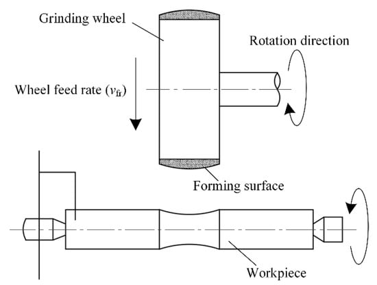
Figure 3.
Schematic diagram of grinding process.
Table 3.
Cutting parameters of grinding process.
2.4. Surface Integrity Characterization and Fatigue Testing
The surface morphology and roughness were measured by the Bruker NPFLEX (Billerica, MA, USA) 3D surface measurement system. The surface roughness is expressed by Ra and Rq. Three sets of data were measured for each sample and then averaged. The axial and tangent (cutting direction) residual stresses were measured by the Proto LXRD (Vancouver, British Columbia, Canada) X-ray residual stress analyzer with Cr-Kα radiation. The tube voltage, tube current, and diffraction angle are 30 kV, 25 mA, and 156.1°, respectively. Three sets of data were measured for each sample and then averaged.
The basic principle of measuring internal residual stress by X-ray diffraction is to measure the diffraction displacement as the original data. The measured result is actually residual strain, and the residual stress is calculated from the residual strain by Hooke’s law. When there is residual stress in the sample, the crystal plane spacing will change. When Bragg diffraction occurs, the diffraction peak will also move, and the size of the shift distance is related to the value of the stress.
For the machining accuracy of the specimen, the 3D size was measured by a Keyence VHX-7000 (Osaka, Japan) microscope system, and the radial run-out was detected by an EWAG WS11 (Dübendorf, Switzerland) universal tool grinder and dial indicator.
The rotating bar bending fatigue test was conducted using the QBWP-6000J (Changchun, Jilin, China) fatigue test machine. The four-point loading is selected according to ISO standard [31], as shown in Figure 4. The fatigue fractography was observed by using a Zeiss Auriga (Oberkochen, Germany) scanning electron microscope.
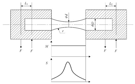
Figure 4.
Schematic diagram of four-point loading tests. (Key, L1 and L2: force arm lengths, D: diameter of gripped or loaded end of specimen, d: diameter of specimen where stress is maximum, r: radius, F: applied force, M: bending moment, S: stress).
The applied force F can be calculated by the following equation:
where S is the required test stress; L is the force arm length; d is the specimen diameter; and M is the bending moment. In this study, L1 = L2 = 200 mm, the stress ratio R = −1, and the test frequency is 50 Hz.
3. Results and Discussion
3.1. Surface Roughness and Morphology
The 3D surface morphology of the specimens after DHT and grinding is shown in Figure 5. The red areas represent the peaks, and the blue areas represent the valleys. Compared with the grinding process, the DHT process produces a smoother machined surface and more uniform feed marks.
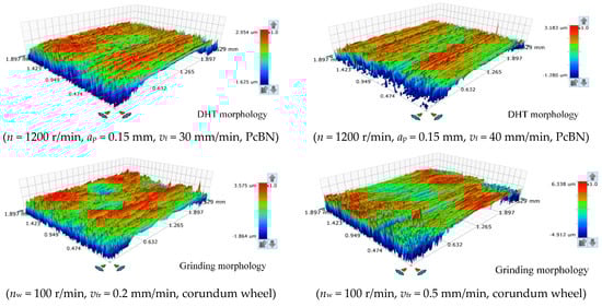
Figure 5.
Comparison of 3D surface morphology after DHT and grinding processes.
Figure 6 shows the effects of DHT process parameters (n, ap, and vf) on the surface roughness. In general, the surface roughness decreases with the increase in n. This is because the increase in n can reduce the built-up edge on the machined surface, and reduce the plastic deformation of the workpiece, thus reducing the surface roughness. The increase in ap leads to more plastic deformation and larger surface roughness. With the increase in vf, the remaining volume of the material that has not been removed increases, and the height of the built-up edge and the machining burr increases, so the surface roughness deteriorates. The minimum surface roughness Ra obtained by the DHT process is 0.172 μm.
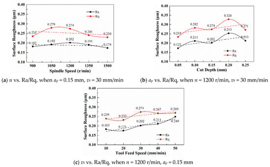
Figure 6.
Effect of cutting parameters on surface roughness during DHT process.
Figure 7 shows the effects of grinding process parameters (nw and vfr) on the surface roughness. From the overall trend, the surface roughness increased with the increasing nw. As the nw increases, the contact arc length between the wheel and the workpiece increases, which increases the material removal rate and the maximum undeformed chip thickness. The surface roughness initially decreased and then increased with the increasing vfr. The increasing vfr during plunge-grinding increases the wheel radial feed per unit time, resulting in increased friction between the abrasive particles and the workpiece and increased plastic deformation of the grinding layer material, so the surface roughness value gradually increases. The minimum surface roughness Ra formed by the grinding process is 0.314 μm.
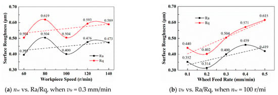
Figure 7.
Effect of cutting parameters on surface roughness during grinding process.
3.2. Residual Stress
Figure 8 shows the effects of DHT process parameters (n, ap, and vf) on the surface residual stress. From an overall viewpoint, the axial stress σy first decreased and then increased with the increasing n. As the n increases, the mechanical stress and plastic deformation effect increase, and the surface compressive residual stress finally increases [32,33,34,35]. An increase in ap increases the cutting layer volume and the plastic deformation zone, so σy increases. The axial stress σy tends to decrease with the increasing vf. As the vf increases, the material removal rate increases, and the friction between the workpiece and tool increases, resulting in more cutting heat and aggravating the effect of thermal stress. The maximum σy and σx obtained by the DHT process are −762.6 MPa and −442.8 MPa, respectively.
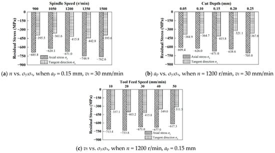
Figure 8.
Effect of cutting parameters on surface residual stress during DHT process.
Figure 9 shows the effects of grinding parameters (nw and vfr) on the residual stress. The effect of nw on residual stress is not monotonic, and the maximum compressive residual stress is formed when nw = 80 r/min. As the nw increases, the average undeformed chip thickness and grinding heat increase, while the continuous increase in nw makes the heat source move faster along the machined surface and reduces the effect of thermal stress, so the residual stress fluctuates. The compressive residual stress is the largest when vfr = 0.1 mm/min and then tends to decrease. As the vfr increases, the friction between the wheel and workpiece intensifies, the grinding heat increases, and then the thermoplastic deformation formed by the grinding heat increases, so the compressive residual stress decreases under the effect of thermal stress. The maximum σy and σx formed by the grinding process are −456.2 MPa and −221.2 MPa, respectively.
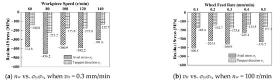
Figure 9.
Effect of cutting parameters on surface residual stress during grinding process.
According to the surface roughness and residual stress values, the optimal parameters of different processes are determined, as shown in Table 4. The surface roughness and residual stress produced by the DHT process are better, which is related to the axial feed of the cutting tool. At the same time, the larger corner radius of the PcBN tool is beneficial to reduce the surface roughness and increase the surface compressive stress. Tool geometry significantly affects the surface roughness of the machined surface [36,37].
Table 4.
Optimized process parameters and surface integrity.
3.3. Machining Accuracy
The processed specimen is shown in Figure 10, and its radial run-out and 3D size accuracy were tested. The effect of different processes on the radial run-out of the specimen is shown in Figure 11, and the abscissa (No.) corresponds to the different parameters in Table 2 and Table 3. The radial run-out produced by DHT and grinding processes fluctuated around the fitting lines of 0.02–0.04 mm and 0.05–0.06 mm. The machining accuracy of the specimen meets the run-out tolerance requirement of dynamic radial run-out ≤0.06 mm of fatigue test. Compared with the grinding, the machining accuracy of the sample obtained by the DHT process is better.
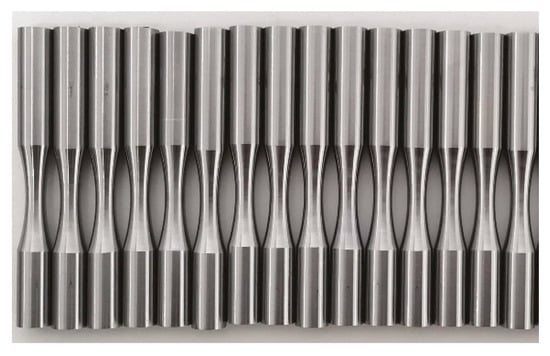
Figure 10.
Hourglass-shaped specimen.
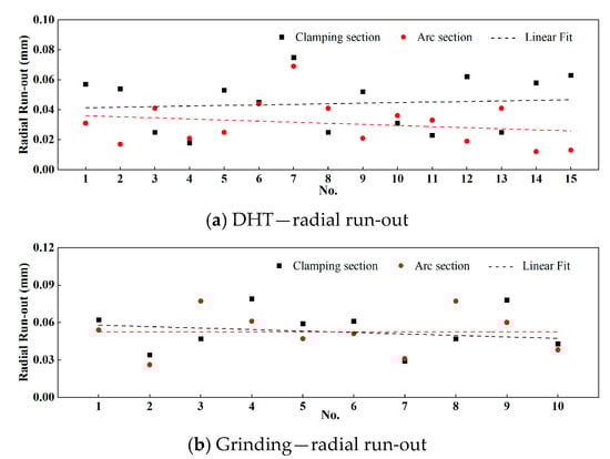
Figure 11.
Radial run-out of specimens with different machining processes.
The 3D size of the specimens was randomly tested to further evaluate the machining accuracy of the DHT process. The specimen, cloud image, and size of the 3D measurement are shown in Figure 12a–c, respectively.
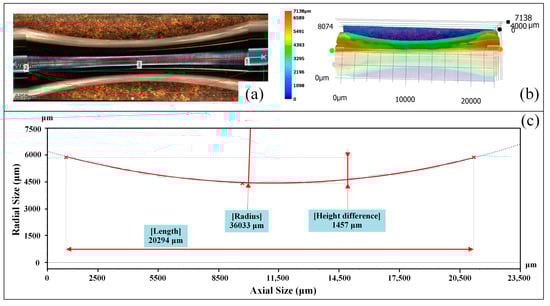
Figure 12.
3D measurement results of specimen in DHT process: (a) Arc section of the specimen (b) Cloud image (c) 3D measurement size.
The length, radius, and difference in the height of the specimen arc section are 20.294 mm, 36.033 mm, and 14.57 mm, respectively. The length deviation, radius deviation, and height deviation of the specimen arc section processed by the DHT process are 0.8%, 0.1%, and 2.8%, respectively. The machining accuracy can meet the size requirements shown in Figure 1.
3.4. Fatigue Test and Fractography
The fatigue specimens were processed according to the optimum parameters in Table 4, and then the fatigue test was conducted. The rotating bar bending fatigue test refers to the ISO standard [31], and the test stress determined after the pre-experiment is 1400 MPa. The bending fatigue life of the specimens under different processes is shown in Table 5.
Table 5.
Bending fatigue life of specimens processed by different machining processes.
After the fatigue fracture, the fatigue fractography of specimens is analyzed. The fatigue fractography of specimens after the DHT and grinding processes are shown in Figure 13 and Figure 14, respectively.
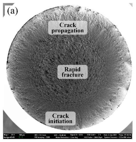
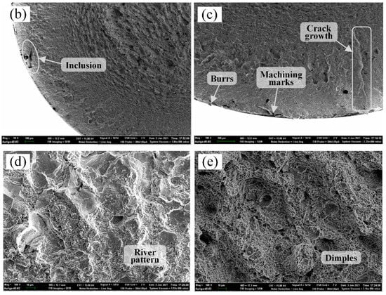
Figure 13.
Fatigue fractography of the specimen obtained by DHT process: (a) 28× full; (b) 50× crack initiation zone; (c) 100× machining marks; (d) 500× crack propagation zone; (e) 500× rapid fracture zone.
Figure 14.
Fatigue fractography of the specimen obtained by grinding process: (a) 28× full; (b) 50× crack initiation zone; (c) 100× machining marks; (d) 500× crack propagation zone; (e) 500× rapid fracture zone.
Figure 13 and Figure 14a show that the fatigue fractography of specimens is divided into three zones, including fatigue crack initiation, crack propagation, and rapid fracture. There are many tiny strip-shaped cracks and crack growth in the crack initiation zone. The crack propagation zone is relatively smooth, and the rapid fracture zone is a ridge-like pattern with obvious plastic deformation. Figure 13 and Figure 14b show the crack initiation zone magnified by 50×, with obvious tiny cracks and some inclusions in the fracture. Figure 13 and Figure 14c show machining marks and burrs on the surface of the fractured samples, and there is a relatively apparent large crack near the machining marks. The machining defects and marks on the specimen surface will cause large stress concentrations and become the origin of cracks.
The crack propagation zone of the DHT-processed specimen is characterized by river patterns in Figure 13d, indicating that this zone is a cleavage fracture and has high brittleness. The characteristics of the crack propagation zone are relatively smooth and have almost no plastic deformation, indicating that the crack propagation zone of fatigue is a brittle fracture. The crack propagation zone in Figure 14d is characterized by fractures along the grain boundaries of different orientations, which are crystalline and stone-shaped, and belong to intergranular fractures. There is no obvious plastic deformation in this zone, the corresponding full fracture surface is relatively smooth, and the fracture type is a brittle fracture.
Figure 13 and Figure 14e are the fatigue fractography of the rapid fracture zone. The fracture characteristics of the rapid fracture zone are dimple patterns, and the formation mechanism is micropore aggregation. The rapid fracture zone shows a ridge-like pattern with obvious plastic deformation. Therefore, the fracture type of the rapid fracture zone is a ductile fracture. Further, the size and shape of the dimples are different for the specimens processed by different processes. The dimple pattern after the DHT process is that small dimples are densely arranged around larger dimples. The dimple size and shape of the grinding are relatively uniform and uneven, respectively. Material properties and surface residual stress generated by the process are also the main factors affecting the size and shape of the dimples.
Compared with grinding, the DHT process has the advantages of low pollution emission, high machining-induced surface integrity, and high machining accuracy. The DHT process has the potential to improve machining efficiency, reduce processing costs, and realize sustainable manufacturing.
4. Conclusions
The conclusions can be summarized as follows:
The surface roughness and surface residual stress produced by the DHT process are better than the grinding process, which is related to the larger corner radius and the axial feed of the PcBN tool.
The fatigue performance of the specimens by the DHT process is better, which is analyzed from the perspective of surface integrity. The results show that the compressive residual stress improves fatigue performance, and reducing the surface roughness can improve bending fatigue life.
The characteristics of the DHT process are significant for improving machining efficiency, reducing processing costs, and achieving sustainable manufacturing. The DHT process can provide a reference for the precision machining of complex rotating surfaces of hardened steel.
In future research, the distribution of residual stress and hardness will be used to further reveal the impact of machining-induced surface integrity on fatigue performance. At the same time, using microstructure characterization to analyze the affected areas caused by the DHT process is also a future research plan.
Author Contributions
Y.Z.: conceptualization, supervision, and writing—editing. S.Y.: experiment, validation, software, and writing—original draft preparation. W.G.: theoretical guidance, supervision, software, and writing—original draft preparation. X.Y.: supervision, software, and writing—original draft preparation. M.Z.: supervision, software, and writing—original draft preparation. Z.P.: conceptualization, supervision, and writing—editing. All authors have read and agreed to the published version of the manuscript.
Funding
The authors gratefully acknowledge the financial support for this work by the National Natural Science Foundation of China (No. U1804254).
Institutional Review Board Statement
Not applicable.
Informed Consent Statement
Not applicable.
Data Availability Statement
Data will be made available on request.
Conflicts of Interest
The authors declare that they have no known competing financial interest or personal relationships that could have appeared to influence the work reported in this paper.
References
- Guo, Y.; Yen, D.W. Hard turning versus grinding—The effect of process-induced residual stress on rolling contact. Wear 2004, 256, 393–399. [Google Scholar] [CrossRef]
- Zhang, Y.; Yuan, S.; Yang, X.; Wang, D. Effect of process parameters on hardness and microstructure of 18CrNiMo7-6 carburized steel in high-speed cylindrical grinding. Int. J. Adv. Manuf. Technol. 2022, 124, 3137–3147. [Google Scholar] [CrossRef]
- Hussain, G.; Alkahtani, M.; Alsultan, M.; Buhl, J.; Gupta, M.K. Chip formation, cutting temperature and forces measurements in hard turning of Gcr15 under the influence of PcBN chamfering parameters. Measurement 2022, 204, 112130. [Google Scholar] [CrossRef]
- BBoing, D.; Ganea, A.; Brohede, U.; Stålnacke, E.; Norgren, S. The impact of the retained austenite in the case-hardened steels on the crater wear formation of the PcBN tools. Wear 2021, 476, 203691. [Google Scholar] [CrossRef]
- Guo, Y.; Warren, A. The impact of surface integrity by hard turning vs. grinding on fatigue damage mechanisms in rolling contact. Surf. Coat. Technol. 2008, 203, 291–299. [Google Scholar] [CrossRef]
- Jouini, N.; Revel, P.; Thoquenne, G. Influence of surface integrity on fatigue life of bearing rings finished by precision hard turning and grinding. J. Manuf. Process. 2020, 57, 444–451. [Google Scholar] [CrossRef]
- Peng, Z.; Zhang, X.; Zhang, D. Improvement of Ti–6Al–4V surface integrity through the use of high-speed ultrasonic vibration cutting. Tribol. Int. 2021, 160, 107025. [Google Scholar] [CrossRef]
- Peng, Z.; Zhang, D.; Zhang, X. Chatter stability and precision during high-speed ultrasonic vibration cutting of a thin-walled titanium cylinder. Chin. J. Aeronaut. 2020, 33, 3535–3549. [Google Scholar] [CrossRef]
- Peng, Z.; Zhang, X.; Zhang, D. Performance evaluation of high-speed ultrasonic vibration cutting for improving machinability of Inconel 718 with coated carbide tools. Tribol. Int. 2020, 155, 106766. [Google Scholar] [CrossRef]
- Zhang, X.; Peng, Z.; Liu, L.; Zhang, X. A Tool Life Prediction Model Based on Taylor’s Equation for High-Speed Ultrasonic Vibration Cutting Ti and Ni Alloys. Coatings 2022, 12, 1553. [Google Scholar] [CrossRef]
- Karpuschewski, B.; Schmidt, K.; Beňo, J.; Maňková, I.; Prilukova, J. Measuring procedures of cutting edge preparation when hard turning with coated ceramics tool inserts. Measurement 2014, 55, 627–640. [Google Scholar] [CrossRef]
- Pan, Y.; Kang, R.; Bao, Y.; Yin, S.; Dong, Z. Study on tool wear mechanism of single-crystal diamond in ultrasonic vibration elliptical cutting of tungsten heavy alloy. Wear 2023, 516–517, 204616. [Google Scholar] [CrossRef]
- Tang, L.; Gao, C.; Huang, J.; Shen, H.; Lin, X. Experimental investigation of surface integrity in finish dry hard turning of hardened tool steel at different hardness levels. Int. J. Adv. Manuf. Technol. 2014, 77, 1655–1669. [Google Scholar] [CrossRef]
- Holubjak, J.; Pilc, J.; Czánová, T.; Martikáň, P.; Mital, D.; Mrázik, J. Studying of cutting conditions when hard turning and their impact on integrity of shaped-complex surfaces. MATEC Web Conf. 2018, 157, 05010. [Google Scholar] [CrossRef]
- Kundrak, J.; Gyani, K.; Bana, V. Roughness of ground and hard-turned surfaces on the basis of 3D parameters. Int. J. Adv. Manuf. Technol. 2007, 38, 110–119. [Google Scholar] [CrossRef]
- Martell, J.J.; Liu, C.R.; Shi, J. Experimental investigation on variation of machined residual stresses by turning and grinding of hardened AISI 1053 steel. Int. J. Adv. Manuf. Technol. 2014, 74, 1381–1392. [Google Scholar] [CrossRef]
- Panda, A.; Das, S.R.; Dhupal, D. Surface Roughness Analysis for Economical Feasibility Study of Coated Ceramic Tool in Hard Turning Operation. Process. Integr. Optim. Sustain. 2017, 1, 237–249. [Google Scholar] [CrossRef]
- Sarnobat, S.; Raval, H. Experimental investigation and analysis of the influence of tool edge geometry and work piece hardness on surface residual stresses, surface roughness and work-hardening in hard turning of AISI D2 steel. Measurement 2018, 131, 235–260. [Google Scholar] [CrossRef]
- Smith, S.; Melkote, S.N.; Lara-Curzio, E.; Watkins, T.R.; Allard, L.; Riester, L. Effect of surface integrity of hard turned AISI 52100 steel on fatigue performance. Mater. Sci. Eng. A 2007, 459, 337–346. [Google Scholar] [CrossRef]
- Umbrello, D. Investigation of surface integrity in dry machining of Inconel 718. Int. J. Adv. Manuf. Technol. 2013, 69, 2183–2190. [Google Scholar] [CrossRef]
- Hashimoto, F.; Guo, Y.; Warren, A. Surface Integrity Difference between Hard Turned and Ground Surfaces and Its Impact on Fatigue Life. CIRP Ann. 2006, 55, 81–84. [Google Scholar] [CrossRef]
- Zhang, Y.; Yuan, S.; Wang, Z.; Yang, X.; Gao, W. Experimental analysis of residual stress and hardness of 18CrNiMo7-6 steel in high speed cylindrical grinding. Diam. Abras. Eng. 2021, 41, 65–70. [Google Scholar] [CrossRef]
- Obiukwu, O.; Nwafor, M.; Okafor, B.; Grema, L. The effect of surface finish on the low cycle fatigue of low and medium carbon steel. In Proceedings of the 15th ICMIE Congress, Harare, Zimbabwe, 14–15 July 2015; pp. 2–6. [Google Scholar]
- Fu, P.; Jiang, C.; Ji, V. Microstructural Evolution and Mechanical Response of the Surface of 18CrNiMo7-6 Steel after Multistep Shot Peening during Annealing. Mater. Trans. 2013, 54, 2180–2184. [Google Scholar] [CrossRef]
- Springer, P.; Prahl, U. Characterisation of mechanical behavior of 18CrNiMo7-6 steel with and without Nb under warm forging conditions through processing maps analysis. J. Mater. Process. Technol. 2016, 237, 216–234. [Google Scholar] [CrossRef]
- Wang, G.; Zhang, Y.; Gao, C.; Xu, G.; Zhao, M. Effect of residual stress and microstructure on corrosion resistance of carburised 18CrNiMo7-6 steel. Anti-Corros. Methods Mater. 2020, 67, 357–366. [Google Scholar] [CrossRef]
- Zhao, M.; Han, X.; Wang, G.; Xu, G. Determination of the mechanical properties of surface-modified layer of 18CrNiMo7-6 steel alloys after carburizing heat treatment. Int. J. Mech. Sci. 2018, 148, 84–93. [Google Scholar] [CrossRef]
- Zhang, Y.; Wang, S.; Xu, G.; Wang, G.; Zhao, M. Effect of Microstructure on Fatigue-Crack Propagation of 18CrNiMo7-6 High-Strength Steel. Int. J. Fatigue 2022, 163, 107027. [Google Scholar] [CrossRef]
- Ho, H.S.; Li, D.L.; Zhang, E.L.; Niu, P.H. Shot Peening Effects on Subsurface Layer Properties and Fatigue Performance of Case-Hardened 18CrNiMo7-6 Steel. Adv. Mater. Sci. Eng. 2018, 2018, 3795798. [Google Scholar] [CrossRef]
- Fu, P.; Zhan, K.; Jiang, C. Micro-structure and surface layer properties of 18CrNiMo7-6 steel after multistep shot peening. Mater. Des. 2013, 51, 309–314. [Google Scholar] [CrossRef]
- ISO 1143:2010(E); Metallic Materials-Rotating Bar Bending Fatigue Testing. ISO: Geneva, Switzerland, 2010.
- Peng, Z.; Zhang, X.; Zhang, D. Integration of finishing and surface treatment of Inconel 718 alloy using high-speed ultrasonic vibration cutting. Surf. Coat. Technol. 2021, 413, 127088. [Google Scholar] [CrossRef]
- Peng, Z.; Zhang, X.; Zhang, D. Effect of radial high-speed ultrasonic vibration cutting on machining performance during finish turning of hardened steel. Ultrasonics 2020, 111, 106340. [Google Scholar] [CrossRef]
- Zhang, X.; Peng, Z.; Wang, D.; Liu, L. Theoretical analysis of cooling mechanism in high-speed ultrasonic vibration cutting interfaces. Int. J. Therm. Sci. 2023, 184, 108033. [Google Scholar] [CrossRef]
- Zhang, X.; Peng, Z.; Liu, L. A transient cutting temperature prediction model for high-speed ultrasonic vibration turning. J. Manuf. Process. 2022, 83, 257–269. [Google Scholar] [CrossRef]
- Mikolajczyk, T.; Latos, H.; Paczkowski, T.; Pimenov, D.Y.; Szynka, T. Innovative tools for oblique cutting. Procedia Manuf. 2018, 22, 166–171. [Google Scholar] [CrossRef]
- Mikolajczyk, T. Modeling of Minimal Thickness Cutting Layer Influence on Surface Roughness in Turning. Appl. Mech. Mater. 2014, 656, 262–269. [Google Scholar] [CrossRef]


Disclaimer/Publisher’s Note: The statements, opinions and data contained in all publications are solely those of the individual author(s) and contributor(s) and not of MDPI and/or the editor(s). MDPI and/or the editor(s) disclaim responsibility for any injury to people or property resulting from any ideas, methods, instructions or products referred to in the content. |
© 2023 by the authors. Licensee MDPI, Basel, Switzerland. This article is an open access article distributed under the terms and conditions of the Creative Commons Attribution (CC BY) license (https://creativecommons.org/licenses/by/4.0/).