Abstract
YCF104 alloy specimens were fabricated by laser cladding on #45 steel following three different scanning strategies. The microstructure, phase composition, friction coefficient, microhardness, tensile strength, and compressive strength of the specimens formed by different scanning strategies were investigated. The results show that the uniformity of laser remelting of solidified layers improved the uniformity of microstructure and refined the grains. The strengthening effect of the Fe–Cr/Mo solid solution was primarily responsible for the high strength. YCF104 cladding specimens exhibit brittle failure, and with the change of metallurgical bonding form in the overlap area, the compressive strength (the maximum value is 3235 MPa) and the tensile strength (specimen via strategy 3 is 527.44 MPa), there appears significant anisotropy. With the improvement of the uniformity of temperature distribution, the friction coefficient as well as the microhardness decreased when the GCr15 was used as the friction pair. The mechanical anisotropy of the coating is related to both the microstructure and metallurgical bonding strength in the overlap area.
1. Introduction
Compared to the mature machine tool remanufacturing industry abroad, the domestic remanufacturing industry is still in the primary stage. The lack of specifications and standards of remanufacturing processes restrict the development of the machine tool remanufacturing industry toward normalization, standardization, and industrialization. Laser cladding, as a promising surface modification technique, has attracted significant research interest. It is extensively studied for its advantages including fast speed, flexible clamping, no tool usage, no deformation, no slag inclusion, and low porosity and crack extension. Sexton et al. [1] reported that laser cladding technology has the potential to form pore-free and crack-free coatings. Li et al. [2] successfully obtained good metallurgical bonding between the 308L stainless steel (SS) coating and 316L SS substrate (with scrapped or erosive surface) without tools and fixtures. Laser cladding, as a new technology of the 21st century, has gradually become a key technology to promote the development of the remanufacturing industry. Most parts of machine tools are steel parts. In order to ensure the stability and service life of repaired parts, selection of the laser cladding process and the performance of remanufactured parts are very important [3]. Therefore, extensive research efforts have been devoted to the investigation of the laser cladding properties of Fe-based alloy powder [4,5].
Zhang et al. [6] found that the ceramics phase could improve the wear resistance of Fe-based alloy coating. Qu et al. [7] reported that VC-VB/Mo could significantly improve the hardness and wear resistance of the Fe-based alloy coating. Yang et al. [8] assumed that Mn has the potential to improve the non-magnetic properties of the Fe-60%WC composite coating. Yang et al. [9] investigated the effect of Nb contents on the performance of Fe-based alloy coating. Therefore, in order to improve the properties of Fe-based alloy and Fe-based composite coatings, the effects of the addition of some materials to Fe-based alloys has been studied. Tan et al. [10] investigated the effect of strengthening/reinforcement particles (Al2O3 and M7C3) on the microstructure and wear resistance of the matrix composite coatings. The results showed that thermite reactants could enhance the microhardness and wear resistance by increasing the amount of Al2O3 ceramic and M7C3 carbide. Zhang et al. [11] illustrated the relationship between pulse laser parameters and the size of the in situ-formed Ti–V carbide particle. The results indicated that the influence of pulse frequency on carbide particle size was not monotonous, while it exhibited a contrary effect on the hardness and corrosion resistance. By reducing the additional content of CeO2 from 0.5 to 0.25 wt.%, Zhang et al. [12] improved the corrosion resistance of TiC–VC-reinforced Fe-based cladding layers from 3.5 times to 7.33 times. Furthermore, the microstructure that was generated in the laser cladding process was mainly lath martensite and retained austenite. Wang et al. [13] studied the effect of content of Mo on the wear resistance and microstructure of SS coatings. The results showed that 6.0 wt.% of Mo coating led to an excellent wear resistance (3.7 times) compared to free Mo, and the content of Mo played a positive effect on ferrite content. Zhao et al. [14] studied the effect of a ceramic particle (TiC, VC) on the Fe-based alloy coating. Generation of the composite particle (Ti, V)C during the laser cladding process is critical to improving the wear resistance and hardness of the cladding layer. According to the abovementioned studies, the reinforcement particles produced by the reaction between the additional elements and the Fe-based alloy matrix in the cladding process can lead to the enhancement of the properties of cladding layers.
Many systematic explorations and achievements have been made in the research of performance strengthening of Fe-based alloy [15]. However, the effect of process parameters on the performance of the coating is also very important, which can provide the theoretical basis and research direction for further research and application of Fe-based alloy. Zhou et al. [16] fabricated a Cu–Fe-based coating without cracks and pores using laser induction hybrid rapid cladding (LIHRC) technology. The LIHRC was able to provide good properties to the Fe-based alloy with impressive efficiency (four times that of individual laser cladding). S. Zhou and Dai [17] also studied the microstructure evolution of Fe-based/WC composite coating fabricated on steel surface by LIHRC. They reported that the microhardness of the composite coating was three times higher than that of the substrate. Zhou et al. [18] investigated the influence of a Fe-based amorphous matrix composite coating reinforced with various portions of 316L SS powders on the microstructure and mechanical properties. Li et al. [19] prepared a Co–Cr–Fe alloy cladding layer using a combination of laser cladding and friction stir processing, and illuminated the relevant mechanisms for the mechanical and wear properties. Wang et al. [20] investigated the effect of oil lubrication on the wear and contact fatigue damage resistance of Fe-based alloy fabricated by laser cladding. The results showed that the addition of suitable La2O3 content (1.2 wt.%) in the Fe-based alloy coating resulted in a good wear resistance under the oil condition. Karczewski et al. [21] successfully fabricated thin walls with a minimum wall thickness of 0.5 mm using the Fe–16Al alloy powder by laser engineered net shaping; however, the produced specimens exhibited the presence of a number of cracks. Fang et al. [22] found that the phase transformation obviously affected the stress evolution, and in turn, the martensitic transformation characteristic temperature was affected. Nonetheless, the study of the effect of the cladding process on properties and mechanism evolution still needs further exploration.
In this study, the correctness of the start–stop overlap model [23] was verified, and the effects of z-axis increment on the geometrical features and properties of the specimen fabricated by laser cladding using 316L SS [24] were studied. Moreover, Taguchi grey correlation analysis was used to realize the optimization of multiple parameters under multiple responses [25]. By adding ceramic phase in the Fe-based alloy, the wear resistance of the coating was improved [26]. The results indicated that the cladding strategies obviously affect the properties of the specimens. Distribution of the temperature field in the cladding process is closely related to the structure of the coating, which directly affects its performance. The selection of scanning strategy in the cladding process directly determines the temperature field distribution [27]. In order to reduce the laser-cladded layer’s anisotropy, and thus improve the stability and reliability of the laser-cladded specimens, the different scanning strategies were designed and investigated. The relationship between the scanning strategies and the properties of the anisotropy of YCF104 alloy powder was analyzed. Moreover, the relationship between the properties of the anisotropy and the typical microstructure is studied.
2. Experimental
2.1. Experiment Materials
The specimens used in this study were fabricated by laser cladding on the #45 steel substrate using three different scanning strategies. The material of the specimen is YCF104 alloy (Fe-based alloy), and the powder consisted of circular particles of sizes between 53 and 150 μm. Zhang et al. [28] found that nitrogen can improve the hardness and corrosion resistance of the SS. Yadaiah et al. [29] found that the self-protective atmosphere of argon showed a positive effect on the weld bead dimensions and free surface profile formation. Therefore, in this study, the argon gas is used as sending powder gas and shielding gas. The selection of the value of gas flow rate should guarantee both the flow stability of powder feeding and the low oxidation rate of the cladding layer during the cladding process. The composition of #45 steel and YCF104 alloy is presented in Table 1. Drying of the powder is necessary prior to its use. On the one hand, it can prevent the existing water vapor in the cladding layer from forming pores and other defects responsible for reducing the quality of cladding parts. On the other hand, it could prevent the water vapor from reacting with elements in Fe-based alloys at high temperature, which then reduces the quality. The formed oxide dust and solid particles brought by water vapor could also be bonded to the protective mirror in the laser head, which could otherwise reduce the quality of the spot and affect the experimental results.
2.2. Process Design
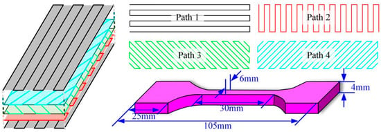
According to the previous experimental studies, the process parameters selected for preparing specimens based on different scanning strategies in this study are laser power 450 W, scanning speed 0.55 mm s–1, powder feeding rate 8.26 g min–1, shielding gas flow rate 12 L min–1, powder feeding gas flow rate 8 L min–1, distance between bottom plane of nozzle and substrate surface 14–16 mm, and defocusing rate 0 mm. Distance between the centers of the adjacent clad tracks was 0.9 mm during transverse overlapping and the distance between the clad paths of the adjacent cladding layer was 0.35 mm during longitudinal overlap. The off-line software RobotArt (PQArt(×86)) was used to design the trajectories of different scanning strategies. Based on the horizontal and vertical overlapping distances obtained from previous experiments, the trajectories were designed and optimized according to the designed cuboid size (35 mm × 25 mm × 15 mm) as shown in Figure 1a–c, respectively. Preparation of the tensile pattern is presented in Figure 1c, and the cuboid size is 115 mm × 30 mm × 12 mm, as shown in Figure 2. The total length of the tensile specimen is 105 mm, the gauge is 30 mm in size with the section size 4 × 6 mm2, the length of parallel segment for clamping is 25 mm, and the width is 20 mm. Furthermore, the scanning strategy 1 (Figure 1a) has the same trajectory in each layer, and the scanning strategy is consistent with the path 1 shown in Figure 2. For scanning strategy 2 (Figure 1b), the scanning directions of the adjacent two layers are perpendicular to each other, and the scanning strategy indicates that the paths 1 and 2 are alternate to each other as presented in Figure 2. Scanning strategy 3 (Figure 1c) involves paths 1, 2, 3 and 4 as presented in Figure 2. Path 1 is perpendicular to path 2, 3 is perpendicular to 4, and the angle between paths 2 and 3 is 45°.
Figure 1.
Compressive specimens design. (a) Scanning strategy 1; (b) Scanning strategy 2; (c) Scanning strategy 3; (d) Size of specimens.
In order to study the effect of different scanning strategies on the compressive strength, microstructure, and wear resistance of cladded specimens, cuboid blocks completed by cladding were utilized (Figure 1d). The specimens were prepared parallel to the cladding direction and perpendicular to the cladding direction, respectively. The dimensions of the compressive specimens were 6 mm × 6 mm × 18 mm and those of the wear-resistant specimens were 10 mm × 10 mm × 5 mm. The surfaces of the compressive specimens were ground using a grinding wheel. The compressive strength and tensile strength of the specimens were tested using a universal testing machine ETM 305D (Shenzhen Xinlangpu Electronic Technology Co., Ltd, Shenzhen, China); during the tensile and compressive test, the loading rate was 2 mm min−1. Effects of different scanning strategies on the compressive properties were analyzed and compared. The morphology of the crushed specimens was observed by scanning electron microscopy (SEM). The specimens used for wear resistance were sanded using sandpaper (240#, 400#, 600#, 800#, 1000#, 1500#, 2000#), and then polished by paste polishing. The wear resistance of polished specimens was tested using a reciprocating friction and wear tester MFT-4000 (Lanzhou Huahui Co., Ltd, Lanzhou, China). The experiment was carried out at room temperature in dry sliding friction; the load was 10 N, the wear speed was 200 mm min−1, and the reciprocating distance was 5 mm. After grinding using sandpaper and polishing paste, the microhardness which was measured using a microhardness tester (EM500-2A, Shanghai Hengyi Co., Ltd, Shanghai, China) was compared under different overlapping modes, a 500 gf load was applied for 10 s, and the spacing between adjacent two points was 600 μm. The microstructures were observed by confocal microscopy (LEXTOLS4100, Olympus, Tokyo, Japan), SEM, and energy dispersive spectroscopy (EDS). Moreover, the mechanism highlighting the effect of scanning strategies on the microstructure was analyzed. It was necessary to use the etching solution (HCl:H2O:FeCl3 = 20:10:1) to cause corrosion before observing the microstructure.
Figure 3 displays that the distribution of the laser energy density in laser cladding process is Gauss distribution [29]. Figure 3a exhibits the temperature distribution of scanning strategy 1’s (Figure 1a) cross-section. Clearly, the temperature in the overlap zone is lower than that in the center of the molten pool when cladding is carried out with a single scanning strategy. The remelting area of the overlap zone is the smallest, which is prone to generate cracks and pores. The difference of temperature gradient in the overlapping zone and clad track central area is large, and thus significant microstructure heterogeneity will be observed. Figure 3b shows the temperature distribution of scanning strategy 2’s (Figure 1b) cross-section. Compared to that in strategy 1, temperature inhomogeneity in strategy 2 gets significantly improved, but it still shows the main area for the appearance of the pores and cracks in the overlap area of adjacent two-layer clad tracks. Figure 3c exhibits the temperature distribution of scanning strategy 3’s (Figure 1c) cross-section. More remelting happens and the temperature grade in overlap area is low. During cladding, the overlap area within the layer and the overlap area between the layers are often the areas where defects occur [27]. The areas where defects occur in each layer are concentrated in the overlap area, thus the direction of each layer gets changed to change the direction of defect generation, thereby weakening the defect [30].
3. Results and Discussion
3.1. Influence of Scanning Strategies on the Microstructure of Forming Parts
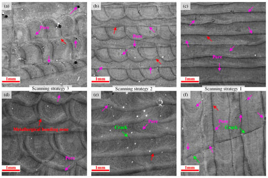
Figure 4 shows the cross-section images obtained under different laser-cladded scanning strategies. The remelting area of scanning strategies 1, 2, and 3 increases in turn, and the six specimens prepared by three scanning strategies along the z-axis direction and parallel to the scanning direction show little cracks and small pores. Moreover, the metallurgical bonding quality in overlap area is good. Owing to the incompletely melted powder bonded on the clad track surface, defects (slag inclusion, porosity, cracks, etc.) tend to occur in the overlap zone [1].
Figure 4.
Cross-section morphology of specimens under different scanning strategies. Along the z-axis direction: (a) Scanning strategy 3; (b) Scanning strategy 2; (c) Scanning strategy 1. Parallel to the scanning direction: (d) Scanning strategy 3; (e) Scanning strategy 2; (f) Scanning strategy 1.
Figure 4 demonstrates that the scanning strategy mainly changes the distribution of the heat-affected zone and the remelting mode of the solidified melted layer. Therefore, the defects in the coating are reduced by remelting the matrix metal with defects. Different scanning strategies change the temperature distribution in the melt layer, which results in changes in the temperature gradient and the heat dissipation ability of the melt layer, and then affects the structure of the melt layer and reduces the defects in the overlapping zone. In order to better understand this impact, different microstructures at the cross-sections were tested.
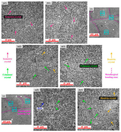
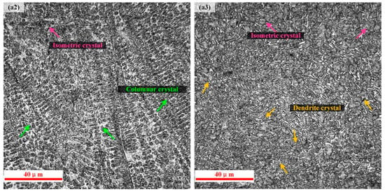
Figure 5 shows the microstructures of different areas in the cross-section along the z-axis direction of scanning strategy 3. According to the microstructure of the overlapping area for which the adjacent two-layer paths are distinguished along the direction of length and width of cladding the rectangular block (as shown in Figure 5a), and the microstructure of the overlapping area for which the adjacent two-layer paths are perpendicular to each other and have an angle of 45° with the rectangular edge (as shown in Figure 5b), the microstructure of the cross-section is found to be fine and uniform. Figure 5(a1,b1) exhibits magnified images of the microstructure of the molten pool. During the cladding process, the internal temperature of the molten pool is the highest, the temperature gradient is small, the heat dissipation is slow, and the grain growth time is long; thus, the main crystal is isometric in nature. Figure 5(a2) shows an enlarged image of the microstructure of the overlapping zone of the two clad tracks. With the increase of the temperature gradient at the overlap, columnar dendrite crystals appear. Remelting leads to continuous growth of columnar dendrite crystals, which eventually become dendrites. Friction, shear, and collision between dendrites break them up into fine dendrites, and thus in this zone, dendrite dominates. Figure 5(b2) exhibits the enlarged image of microstructure of the zone which is around the overlapping zone. During cladding, the temperature in this area is low, the temperature gradient is large, the grain growth time is short after nucleation, and the remelting effect is poor; thus, the secondary growth of grain is not obvious. Therefore, this zone mainly consists of columnar dendrite crystals. Figure 5(a3,b3) shows enlarged images of the microstructure of the overlapping zone between the two layers. This region has a large temperature gradient; therefore, the microstructure mainly consists of columnar dendrite and isometric crystals. There is little difference in the grain size of the entire section, and it has a high homogeneity.
Figure 5.
Microstructures of scanning strategy 3: (a,b) microstructures along the z-axis direction in scanning strategy 3; (a1–a3) enlarged images of an area of (a); (b1–b3) enlarged images of an area of (b).
Figure 6 shows the cross-section of the microstructures formed using scanning strategy 3 parallel to the scanning direction during the cladding process. The metallurgical bonding zone is the remelting mode of the other adjacent layers in the cladding layer. The microstructure in the molten pool still contains mainly isometric crystals, as shown in Figure 6(a1). Within the a2 area, there are mainly columnar dendrite crystals, as shown in Figure 6(a2). Formation of columnar dendrite crystals is effectively inhibited by isometric crystals near the metallurgical bonding zone. Within the a3 area, there are mainly dendrites and isometric crystals, as shown in Figure 6(a3). Complete remelting in the cladding area results in effective refining of the grains and improvement in the uniformity of the microstructure size.
Figure 6.
Microstructure obtained using strategy 3: (a) microstructure parallel to the scanning direction; (a1–a3) enlarged images of an area of (a).
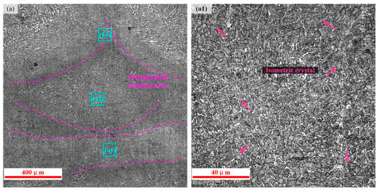
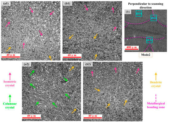
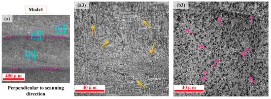
In order to study the effect of scanning strategy on the microstructure of the clad layer, the microstructures obtained using scanning strategies 1 and 2 along the z-axis direction were observed. The measured results of the specimens are presented in Figure 7. The internal microstructure of the molten pool in scanning strategies 1 and 2 mainly consists of isometric crystals, as shown in Figure 7(a1,b3). Figure 7(a3) demonstrates that within the cross-section of scanning strategy 1, the thick dendrite crystals mainly occur in the overlapping zone. In the process of transverse overlapping and longitudinal overlapping, the overlapping area remelts at the edge of the clad track. The molten pool formed in the solidified layer is shallow and small, and thus the remelting quality is poor and the grain size is large in this area. Figure 7(b1,b2) reveals that dendrite and isometric crystals form the major structure. With the increase of remelting area in the overlapping region, the size of the grains decreases and the uniformity of the structure increases relative to scanning strategy 1. The metallurgical quality in this zone is good.
Figure 7.
Microstructures of scanning strategies 1 and 2: (a) microstructure along the z-axis direction in scanning strategy 1; (a1–a3) enlarged image of an area of (a); (b) microstructure along the z-axis direction in scanning strategy 2; (b1–b3) enlarged image of an area of (b).
With the increase of the complexity of scanning strategy between layers, the remelting zone of the clad layer increases, the temperature gradient decreases, and the time difference of grain growth decreases, which reduces the grain size, improves the structural uniformity, and refines the microstructure. Comparative analysis of Figure 5 and Figure 7 demonstrates that the difference of grain size in scanning strategies 1, 2, and 3 decreases in turn, while the homogeneity of the structure increases.
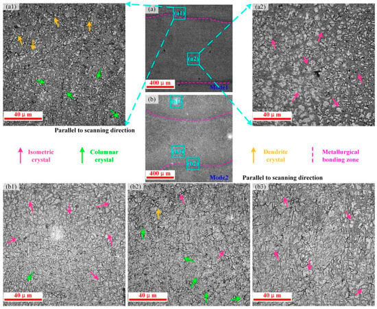
Figure 8 shows the microstructures of scanning strategy 1 and scanning strategy 2 in cross-sections parallel to the scanning direction. The microstructures in the molten pool consist of isometric crystals, and the uniformity of the structure in scanning strategy 2 is higher than that in scanning strategy 1. Regardless of the scanning strategy, columnar dendrite and dendrite crystals are mainly formed in metallurgical bonding zone and in its vicinity area, as shown in Figure 8(a1,b2).
Figure 8.
Microstructures of scanning strategies 1 and 2: (a) microstructure parallel to the scanning direction in scanning strategy 1; (a1–a2) enlarged image of an area of (a); (b) microstructure parallel to the scanning direction in scanning strategy 2; (b1–b3) enlarged image of an area of (b).
Through microstructural analysis under different scanning strategies, the internal structure can be effectively controlled by changing the scanning strategies between layers. The change of scanning strategy mainly leads to the change in the temperature distribution in the cladding process; thus, the structure can be effectively controlled. Owing to the low-temperature gradient, high temperature, and slow heat dissipation, dense isometric crystals are formed after nucleation for a longer growth time. In the overlapping area, the temperature gradient is large, secondary crystallization or even longer duration crystallization occurs during cladding, and the grain continues to grow or the structure remelts and regenerates and finally breaks into fine dendrites or isometric crystals. However, different scanning strategies generate different remelting modes; therefore, the structure of the overlapping zone is different. Defects are most likely to occur in the overlap zone, and thus controlling the structure of the overlapping zone is one of the key factors in controlling the properties of the coating.
3.2. Energy Dispersive Spectroscopy Analysis
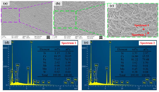
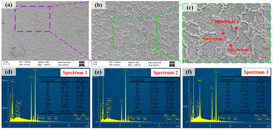
The SEM image and corresponding EDS spectrum of the specimen fabricated via scanning strategy 3 are shown in Figure 9 and Figure 10. The EDS results reveal that the grain boundary is rich in Cr, Ni, Mo, and Nb (as shown in Figure 9d), whereas the grain interior is rich in Si, Fe, and W (as shown in Figure 9e). The grain boundary consists of lamellar phase, as shown in Figure 9c. Figure 10 shows the microstructure of the metallurgical bonding zone of overlapping regions. The grain interior does not contain Nb and W, and the content of elements Fe and Cr are basically the same, as shown in Figure 9e and Figure 10e. Figure 10d demonstrates that the entire rectangular area of spectrum 1 is dominated by Fe, and a significant amount of Cr is also observed. It can be concluded that the structure along the grain boundary is some displacement solid solution about Fe-Cr/Si/Ni/Mo. Figure 10f exhibits the existence of significant amounts of Fe, Cr, and Mo. The Mo enriched in the metallurgical bonding zone formed the solid solution Fe-Cr/Mo/Si/Ni/Nb/W. High Cr content in the laser cladding layer reduced the tenacity of the Fe-based alloy. The solid solution strengthening effect resulted in the lattice distortion of ferrite and then improved the hardness and strength of the coatings.
Figure 9.
The SEM image and corresponding EDS spectra obtained from scanning strategy 3: (a–c) microstructure in scanning strategy 3; (d) Spectrum 1; (e) Spectrum 2.
3.3. Analysis of Friction Coefficient and Microhardness
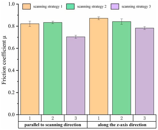
The friction coefficient with wear time was measured using a reciprocating friction and wear tester under different scanning strategies. The experimental results of friction and wear on the cross-section of the specimen parallel to the scanning direction and along the z-axis direction are shown in Figure 11.
The friction coefficient of the specimen in the ‘horizontal direction’ (the specimen along the scanning direction) is lower than that in the ‘vertical direction’ (the specimen along the z-axis direction). The temperature gradient at the bottom of the molten pool in the ‘vertical direction’ is larger than that in the ‘horizontal direction’. In contrast, the temperature gradient at the top of the molten layer in the ‘horizontal direction’ is larger than that in the ‘vertical direction’. Therefore, in the overlapping area, the direction of the growth of the microstructure is different. In the ‘horizontal direction’, the direction of the temperature gradient is basically the same, the uniformity of the temperature distribution is high, and the direction of the growth of the structure in the overlap area is high, as shown in Figure 5(b2), Figure 6(a2), Figure 7(a2) and Figure 8(a1).
Scanning strategy 3 shows the smallest friction coefficient in both ‘horizontal direction’ and ‘vertical direction’ compared to scanning strategy 1 and scanning strategy 2. In scanning strategy 3, the uniformity of structures in the two directions is high, as shown in Figure 5 and Figure 6. This result benefits from the uniform distribution of remelting zone, a small difference of temperature gradient, and uniform distribution of temperature field during the cladding process. In the cladding process, there is no change in the powder composition, and the laser power, scanning speed, and powder feeding rate, etc., remain the same; that is, the energy input is the same. Different scanning strategies can change the temperature input mode, thus affecting the temperature distribution, further controlling the microstructure, and eventually affecting the wear resistance of the clad layer. The dense microstructure leads to an increase in the number of boundaries that need to be destroyed in the wear process, and the wear resistance increases.
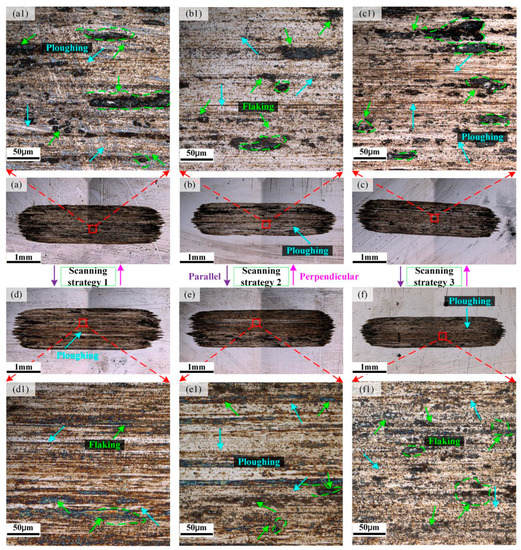
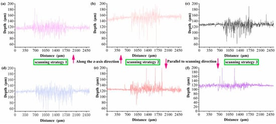
Figure 12 shows the cross-section wear morphology along the z-axis and scanning direction of specimens under different scanning strategies. Figure 12a–f exhibits that the wear surface mainly consists of plow-groove wear scars, and the wear scar width of scanning strategy 1, scanning strategy 2, and scanning strategy 3 decreases in turn. This is consistent with the result of the scratch section profile obtained in Figure 13. Slight adhesion wear is observed on the wear scar surface. The homogeneity of the structure in the ‘horizontal direction’ is higher than that in the ‘vertical direction’, and thus the flaking in the ‘vertical direction’ is more serious than that in the ‘horizontal direction’, as shown in Figure 12(a1–f1). This is mainly attributed to the fact that the structural homogeneity of the ‘horizontal direction’ is higher than that of the ‘vertical direction’, which can be confirmed by Figure 13; scanning strategy 3 (parallel to scanning direction) exhibits the shallowest abrasion mark. Although the internal composition does not change, the number of grains increases and refines. With the increase of remelting area produced by cladding paths and the improvement of uniformity of temperature distribution, the number of grains increases, and then the wear resistance increases.
Figure 12.
Wear morphology. Perpendicular to the scanning direction: (a,a1) scanning strategy 1; (b,b1) scanning strategy 2; (c,c1) scanning strategy 3. Parallel to the scanning direction: (d,d1) scanning strategy 1; (e,e1) scanning strategy 2; (f,f1) scanning strategy 3.
Figure 13.
Sectional profile of scratch under different scanning strategies. Along the z-axis direction: (a) scanning strategy 1; (b) scanning strategy 2; (c) scanning strategy 3; Parallel to scanning direction: (d) scanning strategy 1; (e) scanning strategy 2; (f) scanning strategy 3.
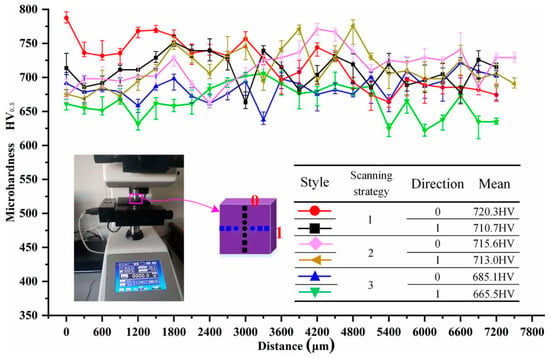
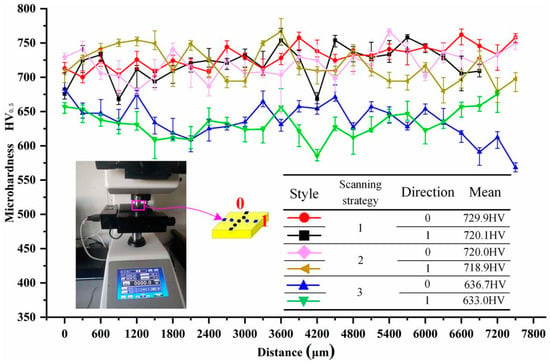
Figure 14 and Figure 15 show the microhardness profiles along the z-axis direction and scanning direction, respectively. The values of average microhardness of different scanning strategies are between 633.0 and 729.9 HV0.5. Different scanning strategies have an obvious effect on the microhardness value of the cladding layer. The microhardness of scanning strategies 1, 2, and 3 decreased in turn. The microhardness of scanning strategy 3 was the minimum, with the value of about 633.0 HV0.5 (the specimen was parallel to the scanning direction), and the microhardness of scanning strategy 1 was the maximum, the value being about 729.9 HV0.5 (the specimen was parallel to the scanning direction).
In the cladding process, scanning strategy 3 shows the best remelting uniformity for the cladded layer, and the effect of reducing defects is obvious. Uniformity of the inner microstructure of the cladding layer is high, and the surface wear resistance is the best. However, the microhardness of the cross-section gets obviously reduced. The scanning strategy providing good wear resistance and uniform structure may not show the best microhardness for the fabricated specimens. Therefore, the scanning strategy in the fabrication process of the YCF104 material should be selected reasonably according to the requirements in the application process.
3.4. Strength Measurement and Analysis
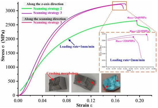
For a comprehensive understanding of the influence of material properties of YCF104 and scanning strategy on the compressive strength of laser cladding specimens, compression experiments were carried out on the specimens. The corresponding experimental results are presented in Figure 16. There is no obvious straight-line part in the curve, and the yield stage is also not observed in the curve. Moreover, the specimen collapsed directly when the deformation was very small. Noteworthy, the compressive strength of YCF104 melt layer was found to be very high. The minimum compressive strength of the specimens was measured to be 2640 MPa (scanning strategy 2 along z-axis direction). The surface of the compression pad was damaged during compression due to the extreme hardness of the specimen. The figure exhibits that the overlap direction of the specimen prepared under scanning strategy 2 (specimen prepared along z-axis direction) is perpendicular to the load direction. Compared to the internal part of the molten pool, the microstructure of the overlap zone is thicker. During compression, the compaction of the microstructure of the overlap zone is easier due to the heterogeneity of the microstructure. Moreover, the vertical overlapping also prevents the splitting of the overlapping region along the X or Y direction during compression. The compressive strength of specimens fabricated under strategy 3 along z-axis and scanning direction is 3235 and 3204 MPa, respectively. The microstructure of the melt layer prepared via strategy 3 is more uniform and compact along the z-axis and scanning direction. Moreover, it shows high resistance toward external compressive stress during compression. When the strain is less than 0.08, the stress increases rapidly, and then it increases slowly with the strain until the specimen gets crushed. Although the extension direction of the overlap area of scanning strategy 3 (specimen prepared along z-axis direction) is perpendicular to the direction of load, the grain size of the overlap zone is refined and the quality of metallurgical bonding in the overlap zone is improved. Furthermore, the microstructure heterogeneity of the molten pool and the overlapping zone is reduced. Therefore, the compressive strength is higher than that for the specimen prepared via scanning strategy 2 following the same method. Microstructural analysis of the specimen fabricated via scanning strategy 3 (specimen prepared along scanning direction) indicates that the angle between overlap direction and load direction is 90°, 0°, and 45°. It will not reduce the deformation resistance unless the scanning direction is at a certain angle to the load direction. This is mainly attributed to the fact that scanning strategy 3 can effectively refine the microstructure of the metallurgical bond and improve its performance. Moreover, the direction of the temperature gradient in the melting layer is also disordered, which increases the anisotropy of the growth direction of the microstructure in the melting layer. The stress–strain curve and the morphology of the specimen after crushing indicate that YCF104 is a brittle material. The fracture morphology after crushing is shown in Figure 17.
Figure 17.
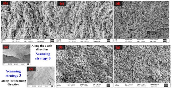
Crushing morphology of scanning strategy 3 specimens. (a) Specimen along the z-axis direction; (b–d) Enlarge images of (a); (e) Specimen parallel to scanning direction; (f,g) Enlarge images of (e).
Fracture morphology reflects the characteristics of part failure to a certain extent. The brittle fracture should be avoided for engineering applications. During compression, all the specimens are directly crushed, and the fractured surfaces show the appearance of many steps. During the process of the propagation of cleavage cracks, the cleavage steps converge to form a river-like pattern, as presented in Figure 17a,e. Under the action of external normal stress, the fracture of the interatomic bond causes brittle transgranular fracturing along a specific crystal plane, as shown in Figure 17(b–d,f,g). Brittle fracturing occurs in YCF104 alloy during compression. However, YCF104 alloy has a high compressive strength when crushed, which can meet the requirements of users based on their specific project.
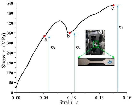
Figure 18 shows the tensile strength of the YCF104 specimen fabricated using scanning strategy 3. The tensile test was conducted to measure the tensile strength of YCF104 alloy powder. The metallurgical bonding direction and overlapping direction of the specimen under scanning strategy 3 are uniform and systematic. A uniform remelting mode improves the quality of metallurgical bonding and reduces internal defects. When the stress is lower than σe, it is proportional to the strain of the specimen, and the original shape can be restored when the stress disappears. In this case, the specimen is in the stage of elastic deformation, and the elastic limit is σe = 337.5 MPa. When the stress exceeds σe, the plastic deformation of the specimen occurs, and the stress disappears. Only part of the deformation can be restored, and the yield limit is σs = 358.71 MPa. When the stress of the specimen exceeds σs, it increases continuously with the increase of stress until it reaches the strength limit of the specimen and is broken, i.e., at this stage the tensile strength of the specimen is σb = 527.44 MPa. According to the fracture morphology based on compressive test and the tensile process, the specimen prepared using YCF104 powder should be brittle material.
The obvious tension–compression asymmetry in laser-formed parts was observed in Figure 16 and Figure 18, which agrees with what was previously reported in the literature [31]. The difference in loading direction of tensile and compression tests resulted in the different work hardening [32]. During the tension process, the alloy exhibited a limited work-hardening behavior and failed at a strain of 0.141. The cracking of grain boundaries of the overlap zones caused the drop in the flow stress [32,33]. With the crack’s extension, the specimen is a failure. However, during the compression test, the alloy showed a more substantial and sustained work-hardening behavior than the tension specimen and failed at a strain of 0.174 (scanning strategies 3) and 0.217 (scanning strategies 2). In this paper, owing to the high microhardness of the laser-cladded specimens (ranges from 633–729.9 HV0.5 (Figure 15)) and big brittleness, the specimen exhibited bigger compressive strength in the compression process. The differences in microstructure characteristic resulted in an uneven stress distribution in the specimen, causing the overlap zone to simultaneously suffer shear and press stress. Therefore, the compressive strength is larger. During the compressive process, the failure form of the specimen is crushed, not jumping up (plastic deformation), and the fracture morphology is an inclined plane [32,34].
4. Conclusions
The YCF104 (Fe-based) alloy specimens were successfully fabricated by laser cladding on #45 steel using three different scanning strategies. The effect of scanning strategies on the microstructure and mechanical properties of YCF104 alloy layer were systematically investigated. The following results were obtained:
- (1)
- With the increase of remelting area produced by cladding paths and the improvement of uniformity of temperature distribution, the microstructure becomes more uniform and the grains become more refined. Moreover, the compressive strength and wear resistance are improved significantly, and the porosity and cracks are reduced.
- (2)
- The Fe–Cr/Mo solid solution strengthening effect led to improvement in the strength of the layers. The grain sizes of specimens fabricated under scanning strategies 1, 2, and 3 decreased in turn, and the homogeneity of the structure increased. The microstructure in the cross-section parallel to the scanning direction was more uniform than along the z-axis direction.
- (3)
- Scanning strategies were closely related to the microstructure. The dense microstructure led to the increase in the number of boundaries that needed to be destroyed in the wear process, reducing the size of the abrasion mark. Compared to z-axis direction, the friction coefficient parallel to the scanning direction (scanning strategies 1, 2, and 3) reduced by 5.7%, 0.1%, and 10.1%, respectively. However, the microhardness of scanning strategies 1, 2, and 3 decreased in turn, and the minimum microhardness of YCF104 was 633.0 HV0.5 among specimens prepared under different scanning strategies.
- (4)
- Laser-cladded YCF104 material belongs to the brittle materials, and with the increase of the uniformity of laser remelting, the compressive strength improved, reaching 3235 MPa. Under the action of external normal stress, the fracture of the interatomic bond caused brittle transgranular fracture along a specific crystal plane, and the cleavage fracture is the main failure of the YCF104 alloy. The tensile strength of the specimen under scanning strategy 3 is 527.44 MPa, the elastic limit is 337.5 MPa, and the yield limit is 358.71 MPa.
Author Contributions
Y.Z.: experimentation, data curation, methodology, resources, and writing the original draft. W.S.: data collection, and manuscript revision. L.C.: experimentation, and data curation, W.W.: supervision, conceptualization, and methodology. T.Y.: conceptualization, methodology, and resources. All authors have read and agreed to the published version of the manuscript.
Funding
This work was supported by the Special Financial Aid to China Postdoctoral Science Foundation (No.2022TQ0116), the China Postdoctoral Science Foundation (No. 2022M721315), the General Program of Chongqing Natural Science Foundation (No. CSTB2022NSCQ-MSX1623), and the Ministry of Industry and Information Technology of China (No. 201675514).
Institutional Review Board Statement
The article follows the guidelines of the Committee on Publication Ethics (COPE) and involves no studies on human or animal subjects.
Informed Consent Statement
Not applicable.
Data Availability Statement
All data generated or analyzed during this study are included in the present article.
Conflicts of Interest
The authors declare no competing interests.
References
- Sexton, L.; Lavin, S.; Byrne, G.; Kennedy, A. Laser cladding of aerospace materials. J. Mater. Process. Technol. 2022, 122, 63–68. [Google Scholar] [CrossRef]
- Li, K.; Li, D.; Liu, D.; Pei, G.; Sun, L. Microstructure evolution and mechanical properties of multiple-layer laser cladding coating of 308 L stainless steel. Appl. Surf. Sci. 2015, 340, 143–150. [Google Scholar] [CrossRef]
- Liu, Y.; Ding, Y.; Yang, L.; Sun, R.; Zhang, T.; Yang, X. Research and progress of laser cladding on engineering alloys: A review. J. Manuf. Process. 2021, 66, 341–363. [Google Scholar] [CrossRef]
- Yin, Y.; Pan, C.; Zhang, R.; Zhao, C.; Qu, Y. The effect of Ti addition on the microstructure and properties of high chromium iron-based coatings. J. Alloys Compd. 2018, 765, 782–790. [Google Scholar] [CrossRef]
- Shanmugam, K.; Lakshminarayanan, A.K.; Balasubramanian, V. Tensile and Impact Properties of Shielded Metal Arc Welded AISI 409M Ferritic Stainless Steel Joints. J. Mater. Sci. Technol. 2009, 25, 181–186. [Google Scholar]
- Zhang, M.; Luo, S.X.; Liu, S.S.; Wang, X.H. Effect of Molybdenum on the Wear Properties of (Ti,Mo)C-TiB2-Mo2B Particles Reinforced Fe-Based Laser Cladding Composite Coatings. J. Tribol. 2018, 140, 051603. [Google Scholar] [CrossRef]
- Qu, K.L.; Wang, X.H.; Wang, Z.K.; Niu, W.Y. Effect of Mo on the VC–VB particles reinforced Fe-based composite coatings. Mater. Sci. Technol. 2017, 33, 333–339. [Google Scholar] [CrossRef]
- Yang, J.; Miao, X.; Wang, X.; Yang, F. Influence of Mn additions on the microstructure and magnetic properties of FeNiCr/60% WC composite coating produced by laser cladding. Int. J. Refract. Met. Hard Mater. 2014, 46, 58–64. [Google Scholar] [CrossRef]
- Yang, J.; Huang, J.; Fan, D.; Chen, S. Microstructure and wear properties of Fe-6 wt.% Cr-0.55wt.% C-Xwt.%Nb laser cladding coating and the mechanism analysis. Mater. Des. 2015, 88, 1031–1041. [Google Scholar] [CrossRef]
- Tan, H.; Luo, Z.; Li, Y.; Yan, F.; Duan, R.; Huang, Y. Effect of strengthening particles on the dry sliding wear behavior of Al2O3-M7C3/Fe metal matrix composite coatings produced by laser cladding. Wear 2015, 324–325, 36–44. [Google Scholar] [CrossRef]
- Zhang, H.; Chong, K.; Zhao, W.; Sun, Z. Effects of pulse parameters on in-situ Ti-V carbides size and properties of Fe-based laser cladding layers. Surf. Coat. Technol. 2018, 344, 163–169. [Google Scholar] [CrossRef]
- Zhang, H.; Zou, Y.; Zou, Z.; Wu, D. Microstructures and properties of low-chromium high corrosion-resistant TiC-VC reinforced Fe-based laser cladding layer. J. Alloys Compd. 2015, 622, 62–68. [Google Scholar] [CrossRef]
- Wang, K.; Chang, B.; Chen, J.; Fu, H.; Lin, Y.; Lei, Y. Effect of Molybdenum on the Microstructures and Properties of Stainless Steel Coatings by Laser Cladding. Appl. Sci. 2017, 7, 1065. [Google Scholar] [CrossRef]
- Zhao, G.L.; Zou, Y.; Zou, Z.D.; Zhang, H. Research on in situ synthesised (Ti,V)C/Fe composite coating by laser cladding. Mater. Sci. Technol. 2015, 31, 1329–1334. [Google Scholar] [CrossRef]
- Wang, Q.T.; Zeng, X.B.; Chen, C.R.; Lian, G.F.; Huang, X. An Integrated Method for multi-objective optimization of multi-pass Fe50/TiC laser cladding on AISI 1045 steel based on grey relational analysis and principal component analysis. Coatings 2020, 10, 151. [Google Scholar] [CrossRef]
- Zhou, S.; Zhang, T.; Xiong, Z.; Dai, X.; Wu, C.; Shao, Z. Investigation of Cu-Fe-based coating produced on copper alloy substrate by laser induction hybrid rapid cladding. Opt. Laser Technol. 2014, 59, 131–136. [Google Scholar] [CrossRef]
- Zhou, S.; Dai, X. Microstructure evolution of Fe-based WC composite coating prepared by laser induction hybrid rapid cladding. Appl. Surf. Sci. 2010, 256, 7395–7399. [Google Scholar] [CrossRef]
- Zhou, H.; Zhang, C.; Wang, W.; Yasir, M.; Liu, L. Microstructure and mechanical properties of fe-based amorphous composite coatings reinforced by stainless steel powders. J. Mater. Sci. Technol. 2015, 31, 43–47. [Google Scholar] [CrossRef]
- Li, R.; Yuan, T.; Qiu, Z.; Zhou, K.; Li, J. Nanostructured Co-Cr-Fe alloy surface layer fabricated by combination of laser clad and friction stir processing. Surf. Coat. Technol. 2014, 258, 415–425. [Google Scholar] [CrossRef]
- Wang, W.J.; Fu, Z.K.; Cao, X.; Guo, J.; Liu, Q.Y.; Zhu, M.H. The role of lanthanum oxide on wear and contact fatigue damage resistance of laser cladding Fe-based alloy coating under oil lubrication condition. Tribol. Int. 2016, 94, 470–478. [Google Scholar] [CrossRef]
- Karczewski, K.; Pe, M.; Zie, M.; Pola, M. Fe-Al thin walls manufactured by Laser Engineered Net Shaping. J. Alloys Compd. 2017, 696, 1105–1112. [Google Scholar] [CrossRef]
- Fang, J.X.; Dong, S.Y.; Wang, Y.J.; Xu, B.S.; Zhang, Z.H.; Xia, D.; He, P. The effects of solid-state phase transformation upon stress evolution in laser metal powder deposition. Mater. Des. 2015, 87, 807–814. [Google Scholar] [CrossRef]
- Zhao, Y.; Yu, T.; Wang, Z.; Chen, H. Calculation and verification of Start/Stop optimum overlapping rate on metal DLF technology. Int. J. Adv. Manuf. Technol. 2018, 99, 437–452. [Google Scholar] [CrossRef]
- Yu, T.; Sun, J.; Qu, W.; Zhao, Y.; Yang, L. Influences of z-axis increment and analyses of defects of AISI 316L stainless steel hollow thin-walled cylinder. Int. J. Adv. Manuf. Technol. 2018, 97, 2203–2220. [Google Scholar] [CrossRef]
- Yu, T.; Yang, L.; Zhao, Y.; Sun, J.; Li, B. Experimental research and multi-response multi-parameter optimization of laser cladding Fe313. Opt. Laser Technol. 2018, 108, 321–332. [Google Scholar] [CrossRef]
- Yang, L.; Yu, T.; Li, M.; Zhao, Y.; Sun, J. Microstructure and wear resistance of in-situ synthesized Ti (C, N) ceramic reinforced Fe-based coating by laser cladding. Ceram. Int. 2018, 44, 22538–22548. [Google Scholar] [CrossRef]
- Zhao, Y.; Yu, T.; Sun, J.; Xi, W.; Bi, X. Effect of laser cladding on forming qualities of YCF101 alloy powder in the different lap joint modes. Int. J. Adv. Manuf. Technol. 2018, 96, 1991–2001. [Google Scholar] [CrossRef]
- Zhang, Z.; Jing, H.; Xu, L.; Han, Y.; Zhao, L.; Zhou, C. Effects of nitrogen in shielding gas on microstructure evolution and localized corrosion behavior of duplex stainless steel welding joint. Appl. Surf. Sci. 2017, 404, 110–128. [Google Scholar] [CrossRef]
- Yadaiah, N.; Bag, S.; Paul, C.P.; Kukreja, L.M. Influence of self-protective atmosphere in fiber laser welding of austenitic stainless steel. Int. J. Adv. Manuf. Technol. 2016, 86, 853–870. [Google Scholar] [CrossRef]
- Birger, E.M.; Moskvitin, G.V.; Polyakov, A.N.; Arkhipov, V.E. Industrial laser cladding: Current state and future. Weld. Int. 2011, 25, 234–243. [Google Scholar] [CrossRef]
- Dadbakhsh, S.; Hao, L.; Sewell, N. Effect of selective laser melting layout on the quality of stainless steel parts. Rapid Prototyp. J. 2012, 18, 241–249. [Google Scholar] [CrossRef]
- Joseph, J.; Stanford, N.; Hodgson, P.; Fabijanic, D.M. Tension/compression asymmetry in additive manufactured face centered cubic high entropy alloy. Scr. Mater. 2017, 129, 30–34. [Google Scholar] [CrossRef]
- Zhao, X.; Lin, X.; Chen, J.; Xue, L.; Huang, W. The effect of hot isostatic pressing on crack healing, microstructure, mechanical properties of Rene88DT superalloy prepared by laser solid forming. Mater. Sci. Eng. A 2009, 504, 129–134. [Google Scholar] [CrossRef]
- Guduru, R.K.; Darling, K.A.; Kishore, R.; Scattergood, R.O.; Koch, C.C.; Murty, K.L. Evaluation of mechanical properties using shear-punch testing. Mater. Sci. Eng. A 2005, 395, 307–314. [Google Scholar] [CrossRef]
Disclaimer/Publisher’s Note: The statements, opinions and data contained in all publications are solely those of the individual author(s) and contributor(s) and not of MDPI and/or the editor(s). MDPI and/or the editor(s) disclaim responsibility for any injury to people or property resulting from any ideas, methods, instructions or products referred to in the content. |
© 2023 by the authors. Licensee MDPI, Basel, Switzerland. This article is an open access article distributed under the terms and conditions of the Creative Commons Attribution (CC BY) license (https://creativecommons.org/licenses/by/4.0/).


