
An Optimization Method for CNC Laser Combination Cutting of Irregular Plate Remainders


Abstract
:1. Introduction
2. Literature Review
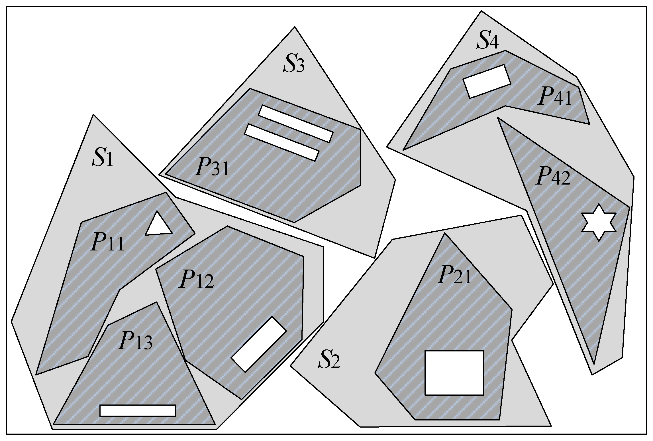
3. Description of the Problem of Combination Cutting of Plate Remainders
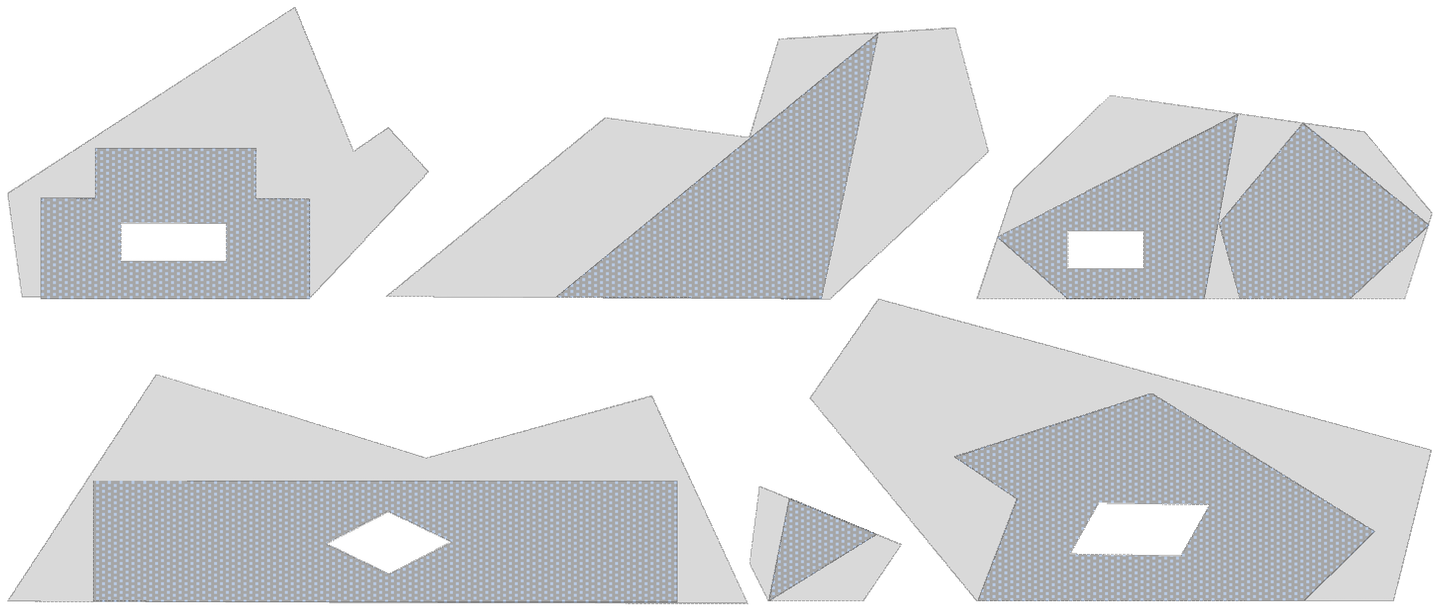
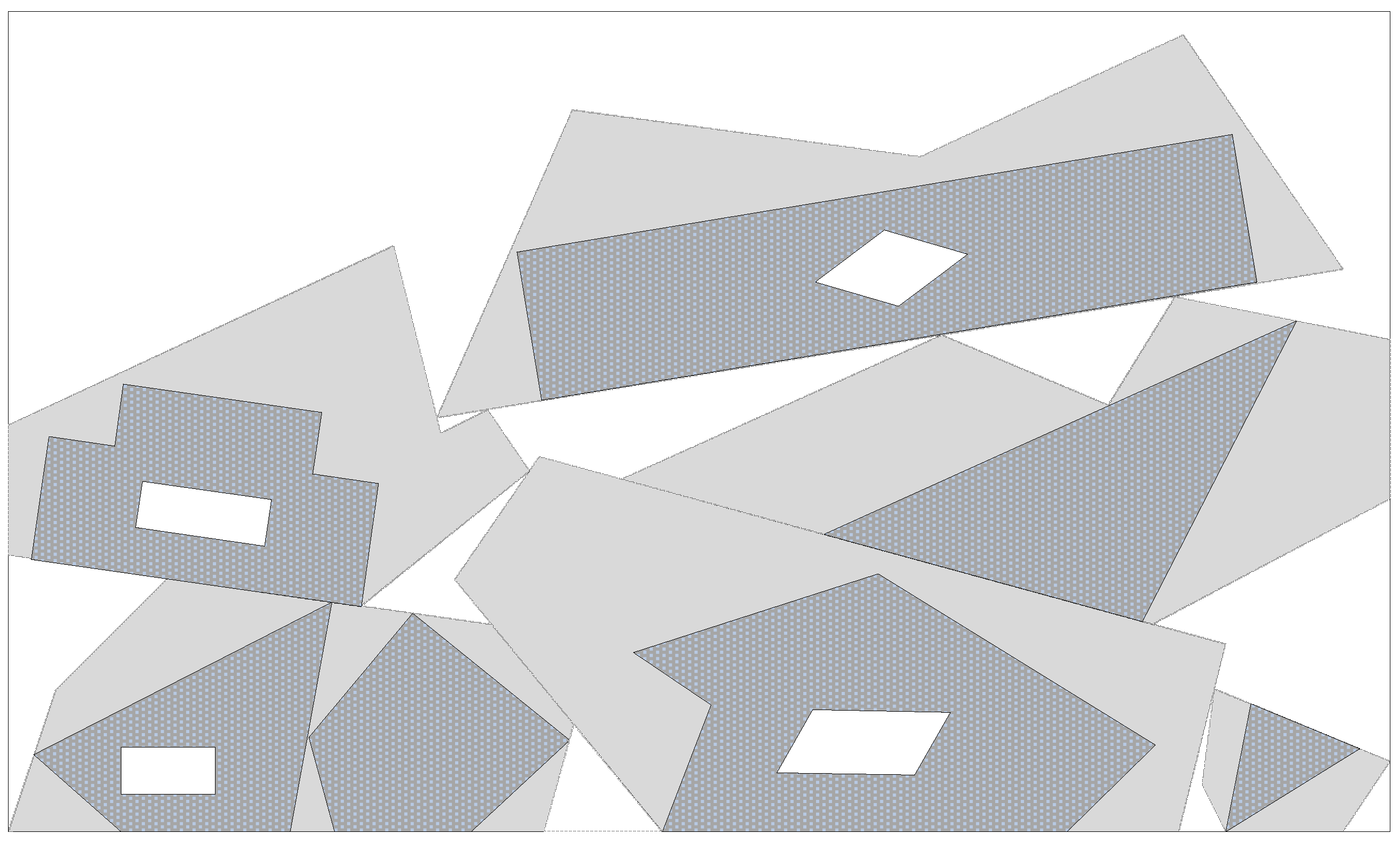
4. Optimization of the Combination Layout of the Plate Remainders
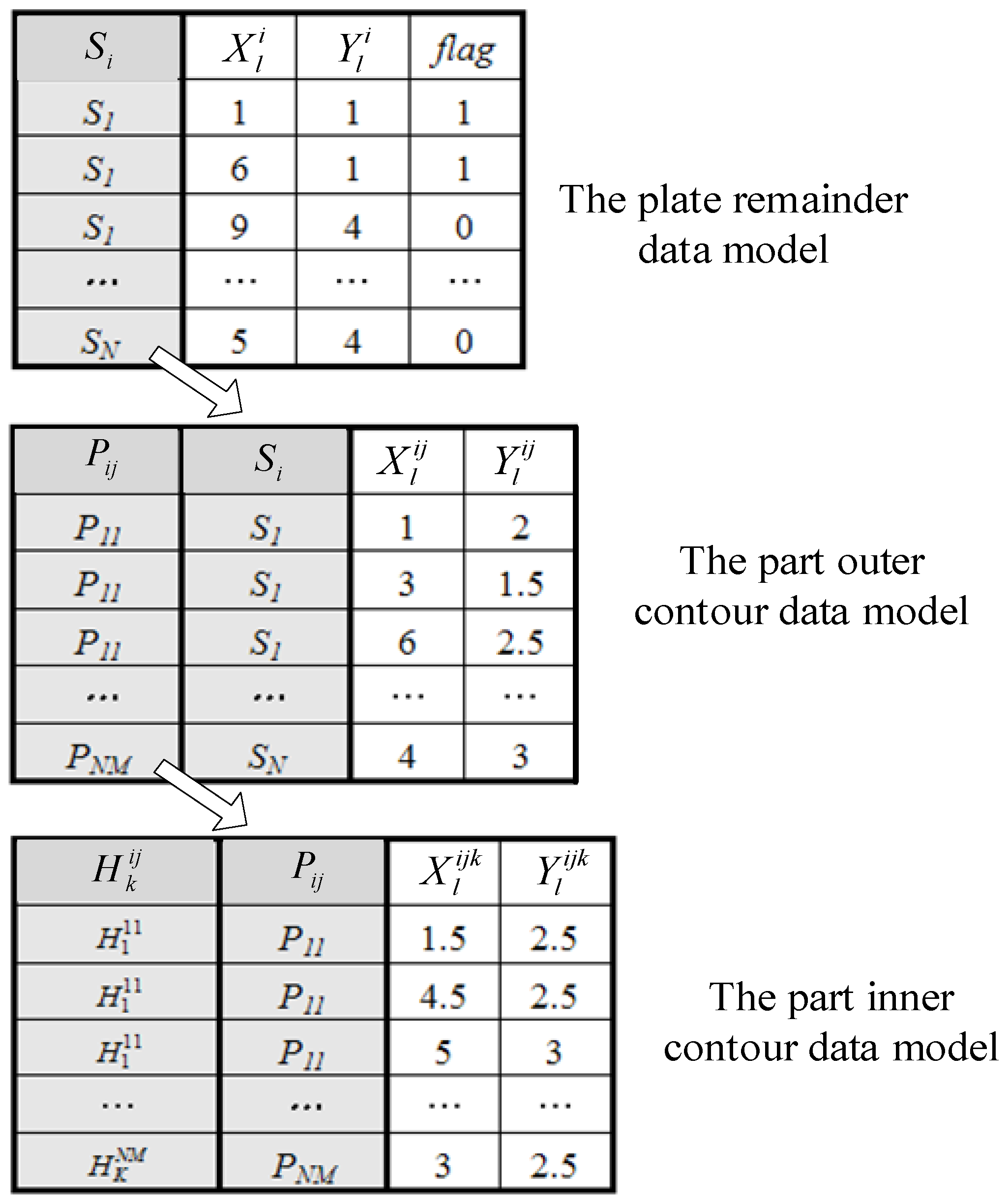
4.1. Graphical Data Model
4.2. The Combination Layout Optimization Method for Plate Remainders
4.2.1. The Coding Method of the Feasible Solution
4.2.2. Fitness Function
4.2.3. Selection Operation
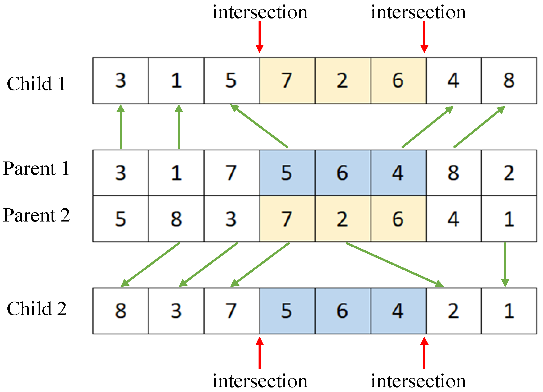
4.2.4. Crossover Operation
4.2.5. Mutation Operation
4.2.6. The Stock Layout Process Based on the Genetic Algorithm
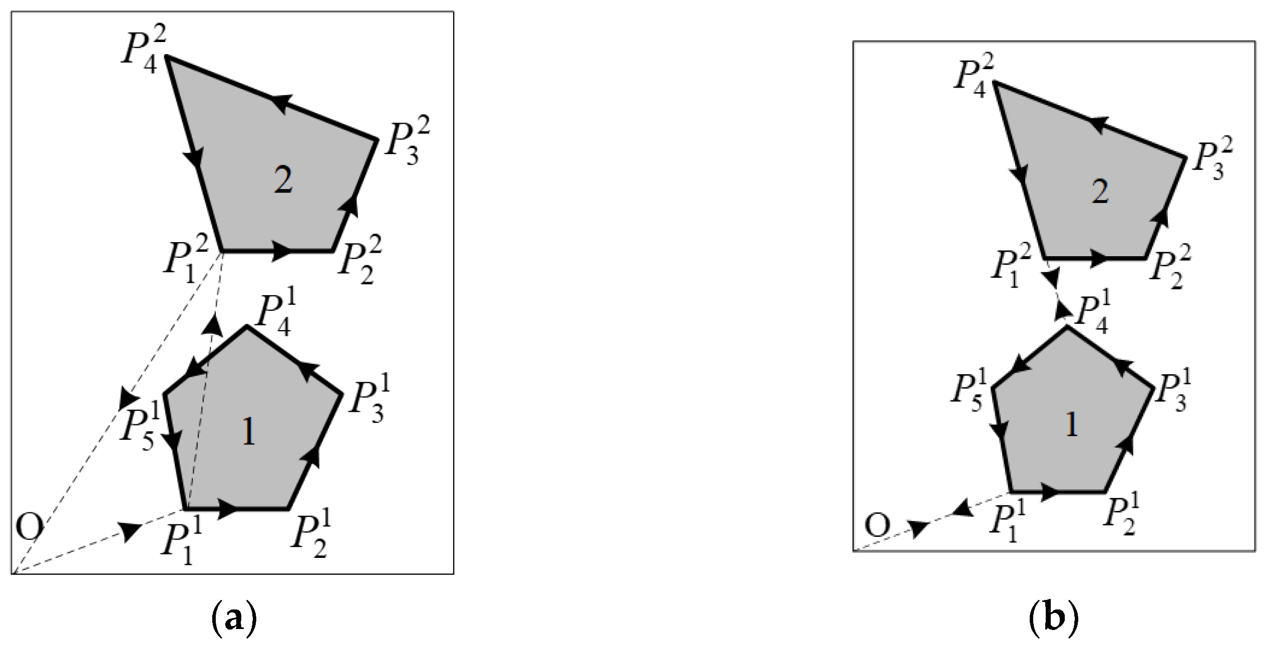
4.3. The Internal-Figure Geometric Transformation of Plate Remainders
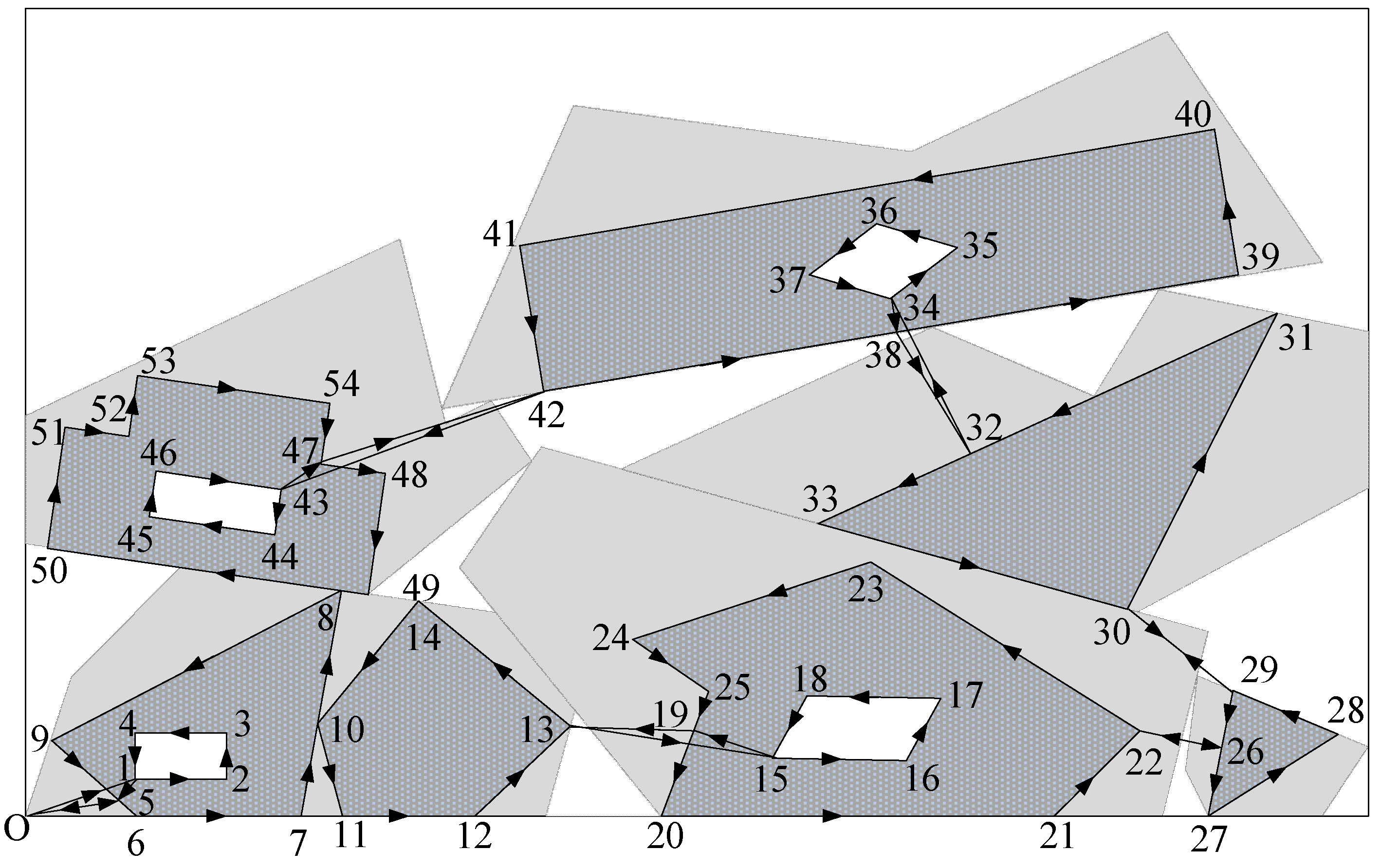
5. Combination Cutting-Path Optimization of Plate Remainders
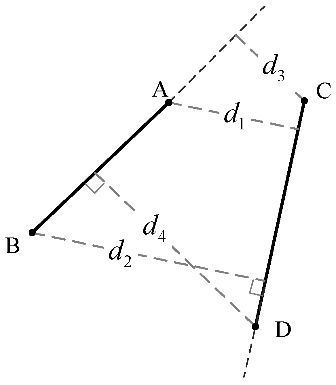
5.1. The Part-Cutting Constraint Rules
- 1.
- The rule of inside-contour priority
- 2.
- The rule of cross-cutting
5.2. The Optimization Model of Cutting Path
5.3. The Optimization Algorithm for the Cutting Path
6. Simulation Experiment
6.1. The Optimization Experiment on the Combination Layout of Plate Remainders
6.2. The Optimization Experiment of the Combination Cutting Path of Plate Remainders
7. Conclusions
Author Contributions
Funding
Institutional Review Board Statement
Informed Consent Statement
Data Availability Statement
Conflicts of Interest
References
- Han, G.-C.; Na, S.-J. A study on torch path planning in laser cutting processes part2: Cutting path optimization using simulated annealing. J. Manuf. Process. 1999, 1, 62–70. [Google Scholar] [CrossRef]
- Castelino, K.; D’Souza, R.; Wright, P.K. Toolpath optimization for minimizing airtime during machining. J. Manuf. Syst. 2002, 22, 173–180. [Google Scholar] [CrossRef]
- Pan, M.; Rao, Y. An integrated knowledge based system for sheet metal cutting-punching combination processing. Knowl. Based Syst. 2009, 22, 368–375. [Google Scholar] [CrossRef]
- Iori, M.; de Lima, V.L.; Martello, S.; Miyazawa, F.K.; Monaci, M. Exact solution techniques for two-dimensional cutting and packing. Eur. J. Oper. Res. 2021, 289, 399–415. [Google Scholar] [CrossRef]
- Oliveiraa, O.; Gamboaa, D.; Silva, E. An introduction to the two-dimensional rectangular cutting and packing problem. Int. Trans. Oper. Res. 2022, 1–29. [Google Scholar] [CrossRef]
- Hopper, E.; Turton, B. A review of the application of meta-heuristic algorithms to 2D strip packing problems. Artif. Intell. Rev. 2001, 16, 257–300. [Google Scholar] [CrossRef]
- Júnior, A.N.; Silva, E.; Francescatto, M.; Rosa, C.B.; Siluk, J. The rectangular two-dimensional strip packing problem real-life practical constraints: A bibliometric overview. Comput. Oper. Res. 2022, 137, 105521. [Google Scholar] [CrossRef]
- Oliveira, J.F.; Júnior, A.N.; Silva, E.; Carravilla, M.A. A survey on heuristics for the two-dimensional rectangular strip packing problem. Pesqui. Oper. 2016, 36, 197–226. [Google Scholar] [CrossRef]
- Albano, A.; Sapuppo, G. Optimal allocation of two-dimensional irregular shapes using heuristic search methods. EEE Trans. Syst. Man Cybern. 1980, 10, 242–248. [Google Scholar] [CrossRef]
- Jose, F.; Oliveira, A.M.; Ferreira, J.S. TOPOS—A new constructive algorithm for nesting problems. OR Spectr. 2000, 22, 263–284. [Google Scholar]
- Liu, H.; He, Y. Algorithm for 2-D irregular-shaped nesting problem based on the NFP algorithm and lowest-gravity-center princilple. J. Zhejiang Univ. Sci. A 2006, 7, 570–576. [Google Scholar] [CrossRef]
- Bortfeldt, A. A genetic algorithm for the two-dimensional strip packing problem with rectangular pieces. Eur. J. Oper. Res. 2006, 172, 814–837. [Google Scholar] [CrossRef]
- Leung, S.C.; Zhang, D.; Zhou, C.; Wu, T. A hybrid simulated annealing metaheuristic algorithm for the two-dimensional knapsack packing problem. Comput. Oper. Res. 2010, 39, 64–73. [Google Scholar] [CrossRef]
- Gomes, A.M.; Oliveira, J.F. Solving irregular strip packing problems by hybridising simulated annealing and linear programming. Eur. J. Oper. Res. 2006, 171, 811–829. [Google Scholar] [CrossRef]
- Dewil, R.; Vansteenwegen, P.; Cattrysse, D. A review of cutting path algorithms for laser cutters. Int. J. Adv. Manuf. Technol. 2016, 87, 1865–1884. [Google Scholar] [CrossRef]
- Kumar, S.; Gupta, A.K.; Chandna, P. Minimization of non-productive time during 2.5 D milling. Int. J. Ind. Manuf. Eng. 2014, 8, 1155–1160. [Google Scholar]
- Gupta, A.; Chandna, P.; Tandon, P. Hybrid genetic algorithm for minimizing non productive machining time during 2.5 D milling. Int. J. Eng. Sci. Technol. 2011, 3, 183–190. [Google Scholar] [CrossRef]
- Hajad, M.; Tangwarodomnukun, V.; Jaturanonda, C.; Dumkum, C. Laser cutting path optimization with minimum heat accumulation. Int. J. Adv. Manuf. Technol. 2019, 105, 2569–2579. [Google Scholar] [CrossRef]
- Hajad, M.; Tangwarodomnukun, V.; Jaturanonda, C.; Dumkum, C. Laser cutting path optimization using simulated annealing with an adaptive large neighborhood search. Int. J. Adv. Manuf. Technol. 2019, 103, 781–792. [Google Scholar] [CrossRef]
- Han, G.-C.; Na, S.-J. Global torch path generation for 2-D laser cutting process using simulated annealing. Intell. Autom. Soft Comput. 1998, 4, 97–108. [Google Scholar] [CrossRef]
- Abdullah, H.; Ramli, R.; Wahab, D.A. Tool path length optimisation of contour parallel milling based on modified ant colony optimisation. Int. J. Adv. Manuf. Technol. 2017, 92, 1263–1276. [Google Scholar] [CrossRef]
- Tian, Y.; Jiang, P. Optimization of tool motion trajectories for pocket milling using a chaos ant colony algorithm. In Proceedings of the 10th IEEE International Conference on Computer-Aided Design and Computer Graphics, IEEE, Beijing, China, 26 December 2007; pp. 389–394. [Google Scholar]
- Abbas, A.T.; Aly, M.F.; Hamza, K. Optimum drilling path planning for a rectangular matrix of holes using ant colony optimisation. Int. J. Prod. Res. 2011, 49, 5877–5891. [Google Scholar] [CrossRef]
- Oysu, C.; Bingul, Z. Application of heuristic and hybrid-GASA algorithms to tool-path optimization problem for minimizing airtime during machining. Eng. Appl. Artif. Intell. 2009, 22, 389–396. [Google Scholar] [CrossRef]
- Xu, H.; Hu, J.; Wu, W. Optimization of 3D laser cutting head orientation based on the minimum energy consumption. Int. J. Adv. Manuf. Technol. 2014, 74, 1283–1291. [Google Scholar] [CrossRef]
- Wang, S.J.; To, S.; Chen, X.D.; Ouyang, X.B. An integrated optimization of cutting parameters and tool path generation in ultraprecision raster milling. Int. J. Adv. Manuf. Technol. 2014, 75, 1711–1721. [Google Scholar] [CrossRef]
- Sui, S.; Li, Y.; Shao, W.; Feng, P. Tool path generation and optimization method for pocket flank milling of aircraft structural parts based on the constraints of cutting force and dynamic characteristics of machine tools. Int. J. Adv. Manuf. Technol. 2015, 85, 1553–1564. [Google Scholar] [CrossRef]
- Eapen, N.A.; Heckendorn, R.B. Cutting path optimization for an automatic cutter in polynomial time using a 3/2 approximation algorithm. Int. J. Adv. Manuf. Technol. 2021, 113, 3667–3679. [Google Scholar] [CrossRef]
- Kiani, K.; Sharifi, M.; Shakeri, M. Optimization of cutting trajectory to improve manufacturing time in computer numerical control machine using ant colony algorithm. Proc. Inst. Mech. Eng. Part B J. Eng. Manuf. 2014, 228, 811–816. [Google Scholar] [CrossRef]
- Ghaiebi, H.; Solimanpur, M. An ant algorithm for optimization of hole-making operations. Comput. Ind. Eng. 2007, 52, 308–319. [Google Scholar] [CrossRef]
- Liu, X.; Hong, Y.; Zhonghua, N.; Jianchang, Q.; Xiaoli, Q. Process planning optimization of hole-making operations using ant colony algorithm. Int. J. Adv. Manuf. Technol. 2013, 69, 753–769. [Google Scholar] [CrossRef]
- Medina-Rodríguez, N.; Montiel-Ross, O.; Sepúlveda, R.; Castillo, O. Tool path optimization for computer numerical control machines based on parallel ACO. Eng. Lett. 2012, 20, 1–8. [Google Scholar]
- Montiel-Ross, O.; Medina-Rodríguez, N.; Sepúlveda, R.; Melin, P. Methodology to optimize manufacturing time for a CNC using a high performance implementation of ACO. Int. J. Adv. Robot. Syst. 2012, 9, 121. [Google Scholar] [CrossRef]
- Abbas, A.T.; Hamza, K.; Aly, M.F. CNC machining path planning optimization for circular hole patterns via a hybrid ant colony optimization approach. Mech. Eng. Res. 2014, 4, 16. [Google Scholar] [CrossRef]
- Manber, U.; Israni, S. Pierce point minimization and optimal torch path determination in flame cutting. J. Manuf. Syst. 1984, 3, 81–89. [Google Scholar] [CrossRef]
- Zhong, T.; Chen, J. A hybrid-coded genetic algorithm based optimisation of non-productive paths in CNC machining. Int. J. Adv. Manuf. Technol. 2002, 20, 163–168. [Google Scholar] [CrossRef]
- Dewil, R.; Vansteenwegen, P.; Cattrysse, D. Sheet metal laser cutting tool path generation: Dealing with overlooked problem aspects. Key Engineering Materials. Key Eng. Mater. 2015, 639, 517–524. [Google Scholar] [CrossRef]
- Kim, Y.; Gotoh, K.; Toyosada, M. Global cutting-path optimization considering the minimum heat effect with microgenetic algorithms. J. Mar. Sci. Technol. 2004, 9, 70–79. [Google Scholar] [CrossRef]
- Lee, M.-K.; Kwon, K.-B. Cutting path optimization in CNC cutting processes using a two-step genetic algorithm. Int. J. Prod. Res. 2006, 44, 5307–5326. [Google Scholar] [CrossRef]
- Jin, M.; Ge, P.; Ren, P. A new heuristic algorithm for two-dimensional defective stock guillotine cutting stock problem with multiple stock sizes. Teh. Vjesn. 2015, 22, 1107–1116. [Google Scholar]
- Li, L.; Wu, Z.; Yu, P.; Cheng, Y. An improved optimization method for NC laser cutting path of sheet metal parts. Forg. Stamp. Technol. 2020, 45, 41–46. [Google Scholar]

| Example | Transfer by the Endpoint of a Segment | Transfer by the Shortest Distance between Segments | Transfer Path |
|---|---|---|---|
| example 1 | 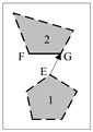 | 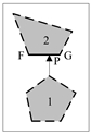 | EG > FP |
| example 2 | 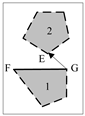 | 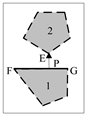 | EG > FP |
| Order Number | Line Segment | The Coordinate of Endpoint 1 | The Coordinate of Endpoint 2 |
|---|---|---|---|
| 1 | (,) | (,) | |
| 2 | (,) | (,) | |
| 3 | (,) | (,) | |
| 4 | (,) | (,) | |
| … | … | …… | …… |
| Z | (,) | (,) |
| Variable | Meaning |
|---|---|
| the maximum number of iterations | |
| the current number of iterations | |
| ant colony number | |
| the total number of part contour line segments | |
| pheromone importance coefficient | |
| heuristic factor importance coefficient | |
| pheromone evaporation coefficient | |
| the minimum value of pheromone | |
| the maximum value of pheromone | |
| the coordinate matrix of line segments | |
| the extended coordinate matrix of line segments (each line segment has two cutting starting points) | |
| the pheromone matrix of line segments | |
| the selective-state matrix of line segments | |
| the order-number matrix of the ant colony path | |
| the coordinate matrix of the ant colony path | |
| the idle-travel matrix of ant colony | |
| the iteration-process matrix | |
| the x-coordinate of ant current point | |
| the y-coordinate of ant current point | |
| the order-number vector of the globally optimal path | |
| the idle travel | |
| the single-iteration optimal solution of idle travel | |
| the global optimal solution of idle travel | |
| the coordinate matrix of the optimal path |
| Instance | The Plate Utilization Ratio | Increased Utilization Ratio Compared to the Other Algorithms | |||
|---|---|---|---|---|---|
| The Tree Search Algorithm (the Best) | TOPOS (the Best) | Our Algorithm (the Average) | The Tree Search Algorithm | TOPOS | |
| Shapes0 | 56.99% | 59.77% | 60.38% | +3.39% | +0.61% |
| Shapes1 | 63.32% | 65.40% | 64.12% | +0.80% | −1.28% |
| Shapes2 | 68.57% | 74.74% | 77.59% | +9.02% | +2.85% |
| Shirts | 78.13% | 81.27% | 81.68% | +3.55% | +0.41% |
| Trousers | 78.80% | 82.76% | 83.62% | +4.82% | +0.86% |
Disclaimer/Publisher’s Note: The statements, opinions and data contained in all publications are solely those of the individual author(s) and contributor(s) and not of MDPI and/or the editor(s). MDPI and/or the editor(s) disclaim responsibility for any injury to people or property resulting from any ideas, methods, instructions or products referred to in the content. |
© 2023 by the authors. Licensee MDPI, Basel, Switzerland. This article is an open access article distributed under the terms and conditions of the Creative Commons Attribution (CC BY) license (https://creativecommons.org/licenses/by/4.0/).
Share and Cite
Li, L.; Wu, Z.; Zhang, Z.; Zhang, Y. An Optimization Method for CNC Laser Combination Cutting of Irregular Plate Remainders. Coatings 2023, 13, 914. https://doi.org/10.3390/coatings13050914
Li L, Wu Z, Zhang Z, Zhang Y. An Optimization Method for CNC Laser Combination Cutting of Irregular Plate Remainders. Coatings. 2023; 13(5):914. https://doi.org/10.3390/coatings13050914
Chicago/Turabian StyleLi, Li, Zhaoyun Wu, Zhongwei Zhang, and Yulan Zhang. 2023. "An Optimization Method for CNC Laser Combination Cutting of Irregular Plate Remainders" Coatings 13, no. 5: 914. https://doi.org/10.3390/coatings13050914
APA StyleLi, L., Wu, Z., Zhang, Z., & Zhang, Y. (2023). An Optimization Method for CNC Laser Combination Cutting of Irregular Plate Remainders. Coatings, 13(5), 914. https://doi.org/10.3390/coatings13050914