Article

Generation of Hybrid Lead Halide CH3NH3PbI3-xClx Perovskite Crystals via Convective Self-Assembly

1
Faculty of Physics, Babes-Bolyai University, 400084 Cluj-Napoca, Romania
2
Interdisciplinary Research Institute on Bio-Nano-Sciences, Babes-Bolyai University, 400271 Cluj-Napoca, Romania
3
INCDO-INOE 2000, Research Institute for Analytical Instrumentation, 400293 Cluj-Napoca, Romania
*
Author to whom correspondence should be addressed.
These authors contributed equally to this work.
Coatings 2023, 13(6), 1130; https://doi.org/10.3390/coatings13061130
Submission received: 2 June 2023 / Revised: 13 June 2023 / Accepted: 17 June 2023 / Published: 20 June 2023

Abstract

:
In this study, we have employed a film deposition technique based on convective forces acting at the triple air–solution–substrate contact line to tune the rate of solvent evaporation and, thus, to exert control over the morphology of the resulting mixed lead halide perovskite CH3NH3PbI3-xClx films. By varying the speed of film deposition while processing at two different temperatures, perovskite crystals of various shapes and dimensions were generated upon the crystallization of the initial perovskite precursor ink. More precisely, longer than half a millimeter 3D needle-like perovskite crystals exhibiting sharp edges co-existing with large cross-like 3D perovskite crystals could only be obtained upon the slow deposition of films at a low sample processing temperature of 17 °C, i.e., under conditions of low solvent evaporation rate. On the contrary, the utilization of higher film deposition speeds and/or processing temperatures led to smaller 3D needle-like or quasi-2D rectangular perovskite crystals that often appeared interconnected and coalesced. Moreover, as it was revealed by the photoluminescence measurements, the emission intensity of perovskite crystals was larger and dominated by a shorter wavelength peak, as compared to the uncrystallized material that emitted much less light, but at a longer wavelength.

1. Introduction

A large part of the scientific community is currently looking to develop new alternative sources of renewable energy that would help in meeting the world’s future, massive energy needs [1,2]. In this direction, perovskites are highly researched materials [3], as their optimized microstructures can display astonishing optoelectronic properties such as long exciton diffusion lengths, high absorption coefficients, good transport of charges, high charge mobilities, high photoluminescence (PL) quantum yield, high defect tolerance, narrow emission linewidths [4,5,6,7,8,9,10,11] and more (details on the investigation and characterization of the optoelectronic properties of perovskite materials can be further consulted in a variety of comprehensive studies reported in the literature [12,13,14,15,16]). Thus, perovskites are excellent photovoltaic materials [17,18,19], not only capable of high photovoltaic performance [20], but also exhibiting tunable bandgaps [21]. Therefore, it is not surprising that one of the most known applications of perovskite materials today is represented by the solar cells [22,23,24]. Since 2009, when Kojima and coworkers fabricated the first solar cell based on a perovskite material which delivered a power conversion efficiency of only 3.8% [25], the technology of perovskite-based solar cells has evolved in a fulminant manner, and nowadays such solar cells have been demonstrated to achieve a power conversion efficiency of about 26% [26,27,28,29]. This high efficiency is partly a result of the improvements made to the perovskite crystal structure, and it is already reaching the efficiency of classical silicon-based solar cells [30,31,32].
Due to their high versatility and tunability, perovskite materials are also being used in many other applied research fields [7,8,9,33,34,35,36,37,38,39]. For instance, in recent years, perovskite-based light-emitting diodes (LEDs) have made tremendous progress, reaching 23.9% in external quantum efficiencies [40]. Nonetheless, the ready-to-use perovskite-based LEDs are still limited due to factors such as poor efficiency of blue emission [41,42,43]. Fortunately, due to novel synthesis and processing methods that are being continuously designed and developed, a significant progress could be made in this direction [10,11,44]. For example, compositional and dimensional engineering can be employed to fabricate quasi-2D perovskite films exhibiting reduced trap density and enhanced PL quantum yield, thus displaying enhanced blue emission properties [10]. The advantages and disadvantages of such strategies, as well as perspectives of fabricating perovskite materials capable of efficient emission of blue light, were recently described in the literature [11]. Moreover, perovskites have been systematically investigated with respect to their suitability in the fabrication of innovative photodetectors for image sensing [34,35,36], field-effect transistors [7,8,9] and memory devices [37,38,39]. Furthermore, perovskites proved their appropriateness in the design of energy storage [45] and various sensor (temperature [33], humidity [46] and light [47]) applications.
All the aforementioned perovskite-based applications owe their functionalities and desired attributes to the microstructure adopted by the perovskite molecules in the active layers or components of each device. By optimizing the perovskite microstructure, which is well known to directly impact the resulting properties of perovskite materials [48,49,50,51], the optoelectronic properties of these materials can be continuously adjusted to lead to better and better device efficiencies. For example, according to available theoretical calculations [52], a power conversion efficiency of over 30% is attainable by perovskite solar cells. Of course, this implies a better understanding of the internal phenomena taking place in such devices, especially with respect to the crystallization of the employed perovskite materials [53,54].
To reach the above goal, efficient perovskite processing methods are needed. Such methods should be able to offer unprecedented control over the resulting perovskite microstructure in the active layers. Of course, a large variety of perovskite deposition and processing methods were already designed and further developed over time, each with its advantages and disadvantages [55,56,57,58,59]. These methods include many different scalable deposition techniques employed to transform specific perovskite solutions into thin films [60], such as spin coating [61], spray coating [62], inkjet printing [63] and blade coating [64]. Here, we also include a simple yet practical method able to produce hybrid lead halide perovskite crystals of controlled morphology from precursor ink solutions of small volumes that were placed into open-air Teflon rings and heated to a desired temperature in order to crystallize at controlled solvent evaporation rates [54].
In this study, we propose fabricating thin films of hybrid lead halide perovskites of altered morphology by employing a deposition technique based on convective forces appearing at the triple air–solution–substrate contact line, i.e., the convective self-assembly (CSA). This technique has already proved itself efficient when self-assembling various organic polymer systems in thin films [65,66,67]. More precisely, we investigate the influence of the CSA deposition speed on the perovskite crystallization process. We further compare the perovskite thin films prepared via CSA with their spin-coated analogs, as well as with the perovskite crystals generated in thin films via drop casting at low temperatures. We observe that films fabricated at low CSA deposition speeds display larger and better-defined perovskite crystals. By varying the CSA deposition speed (or by forcing the solvent to evaporate slowly/faster at lower/higher temperatures), we demonstrate control over the rate of solvent evaporation and, thus, over the resulting perovskite morphology. This enables us to exert a certain control over the crystallization process taking place in the perovskite material and, thus, over the materials’ emission properties.
This work completes other recent approaches taken, for instance, by Liu and co-workers, who promoted the growth of perovskite crystals for photovoltaic applications by favoring the π–π and cation–π interactions through the doping of perovskites with a small molecule [68]. In this way, the crystallization process was optimized to deliver larger perovskite structures that were highly suitable for solar cells. Moreover, in order to establish control over the uniformity of CH3NH3PbI3-xClx perovskite structures and, thus, over the uniformity of the resulting perovskite films, Song and co-workers proposed separating the conventional process used to fabricate perovskite films into the generation of the MAPbI3−xClx mixed halide perovskite powder using a heat-based process and the deposition of MAPbI3−xClx mixed halide perovskite films using the spin coating method [69]. Utilizing this approach, the team has delivered solar cells of better efficiency. Improved photovoltaic efficiency of CH3NH3PbI3-xClx perovskites was also reported when adding copper bromides such as CuBr and especially CuBr2 [70].

2. Materials and Methods

Hybrid lead halide I101 perovskite precursor ink was purchased from Ossila Ltd. (Sheffield, UK), and it was specially formulated for casting in the low-humidity (20% to 35%) air. This ink is suitable to be used in the fabrication of perovskite-based devices such as solar cells or LEDs [54,71]. The I101 perovskite ink was composed of a mixture of precursor materials such as methylammonium iodide (MAI) and lead chloride (PbCl2) dissolved in dimethylformamide (DMF) in a 3:1 ratio [72] and could be coated onto a solid or flexible substrate [73]. Moreover, when exposed to heat, the I101 perovskite ink would suffer chemical reactions and transform into a solid-state CH3NH3PbI3-xClx perovskite material that would exhibit a specific crystal structure [74]. Thus, by changing the annealing conditions, such as the annealing temperature and time, one could achieve a desired crystalline microstructure in the resulting perovskite films.
Thin films of I101 perovskite ink were prepared by spin coating at 2000 rpm for various times ranging from 30 s to a few minutes. Although the spin coating procedure was conducted at room temperature, the utilized perovskite solutions were priorly kept at 17 °C and 30 °C. Moreover, perovskite films of various thicknesses were further fabricated by conducting the CSA procedure at temperatures of 17 °C and 30 °C and at deposition speeds of 1000 µm/s, 500 µm/s, 100 µm/s, 50 µm/s and 10 µm/s. For all films, a regular microscopy cover glass was used as substrate. All substrates were treated in a UV-Ozone cleaner, for a period of 20 min, prior to any further use.
The CSA coater (schematically depicted in Figure 1) comprised a moving translational stage that employed a linear actuator from Zaber Technologies (Zaber, Vancouver, BC, Canada) and had the capacity to reach speeds ranging between ~ 4.7 μm/s and 8 mm/s. A cover glass acting as a blade was fixed in the near vicinity of the substrate at the desired angle, while the perovskite solution was placed on the glass substrate, underneath and nearby the edge of the blade. The temperature of the substrate could be regulated between 15 °C and 35 °C by employing a water-controlled system (Accel 250 LC) acquired from Thermo Scientific (Waltham, MA, USA).
Scanning electron microscopy (SEM) images of perovskite crystals/films were obtained using an FEI Quanta 3D microscope (FEI Company, Eindhoven, The Netherlands) equipped with an EDT detector, operating in high vacuum mode and using an acceleration voltage of 10 kV. Moreover, the optical micrographs of perovskite films were acquired utilizing a KERN OKN-177 optical microscope (Kern & Sohn GmbH, Balingen, Germany) working in the reflectivity mode and equipped not only with various magnification objectives, but also with a KERN ODC 825 (5 Mp) camera. The latter was further connected to a computer via Microscope VIS software that allowed (automatic) recording of images and movies.
The absorption spectra of perovskite thin films were recorded using a V-530 UV–VIS spectrophotometer from Jasco (Oklahoma City, OK, USA) and exhibiting a spectral range of 190–1100 nm. The PL spectra were recorded using an FP-6500 spectrofluorometer from Jasco (Oklahoma City, OK, USA), with the excitation wavelength ranging between 220 and 750 nm. All PL spectra were recorded using an excitation wavelength of 300 nm.

3. Results and Discussion

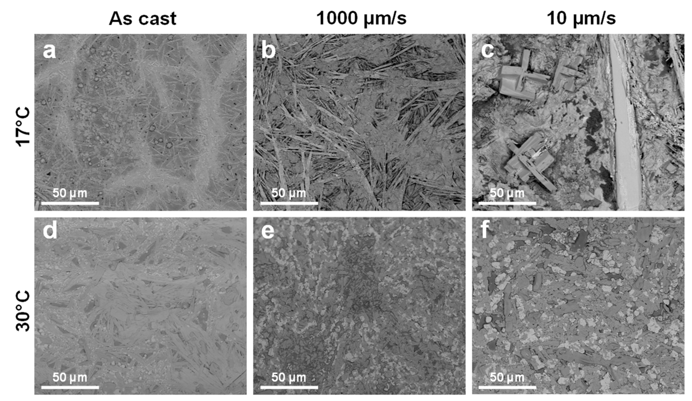
We start this section with Figure 2 where we compare thin films of hybrid lead halide CH3NH3PbI3-xClx perovskites fabricated by spin coating and CSA at both high and low deposition speeds and at two different processing temperatures (i.e., 17 °C and 30 °C; these temperature values were chosen because we had not studied our perovskite system in this temperature range until now; studies performed on the same perovskite system in the 40–110 °C interval were recently published elsewhere [54]). Note here that the spin coating procedure was actually carried out at room temperature, but using perovskite solutions that were priorly kept at 17 °C and 30 °C (Figure 2a,d). We have observed that 10–30 µm long, needle-like perovskite crystalline structures formed during the spin coating at 17 °C. These crystals appeared to be homogeneously, yet randomly, distributed over the surface (Figure 2a). A somewhat similar situation was also portrayed when films were fabricated using the CSA method at a rather high deposition speed (i.e., 1000 µm/s), with the exception that the formed needle-like perovskite crystalline structures exhibited a larger average length of over 50 µm and appeared more interconnected (Figure 2b). This observation could be explained by the fact that the resulting perovskite crystals could be growing over a longer time during the CSA procedure as compared to that corresponding to the spin coating, a process that happened faster and, thus, induced faster evaporation of the solvent. Indeed, when slowing down the rate of solvent evaporation by utilizing the CSA at a much lower deposition speed (i.e., 10 µm/s), both needle-like and cross-like perovskite crystals formed (Figure 2c). Moreover, while the cross-like crystals appeared to have sharp edges and were wider than any of the crystals shown in Figure 2a,b, the needle-like perovskite crystals were large, with some of them well exceeding 500–600 µm in length and 35 µm in width (Figure 2c and Figure S1 in the Supplementary Materials).
When performing the procedures of spin coating and CSA at a higher processing temperature (i.e., 30 °C), the situation was different. The spin coating method led to less-prominent, rather coalesced perovskite crystalline structures. In between, much fewer, yet highly interconnected, needle-like crystals were also appearing randomly distributed on the surface (Figure 2d). Instead, the CSA method, both at a high and a much lower deposition speed, led to perovskite crystals of shapes resembling rectangles rather than needles (Figure 2e,f). Nonetheless, perovskite crystals that formed at a low deposition speed were on average much larger.
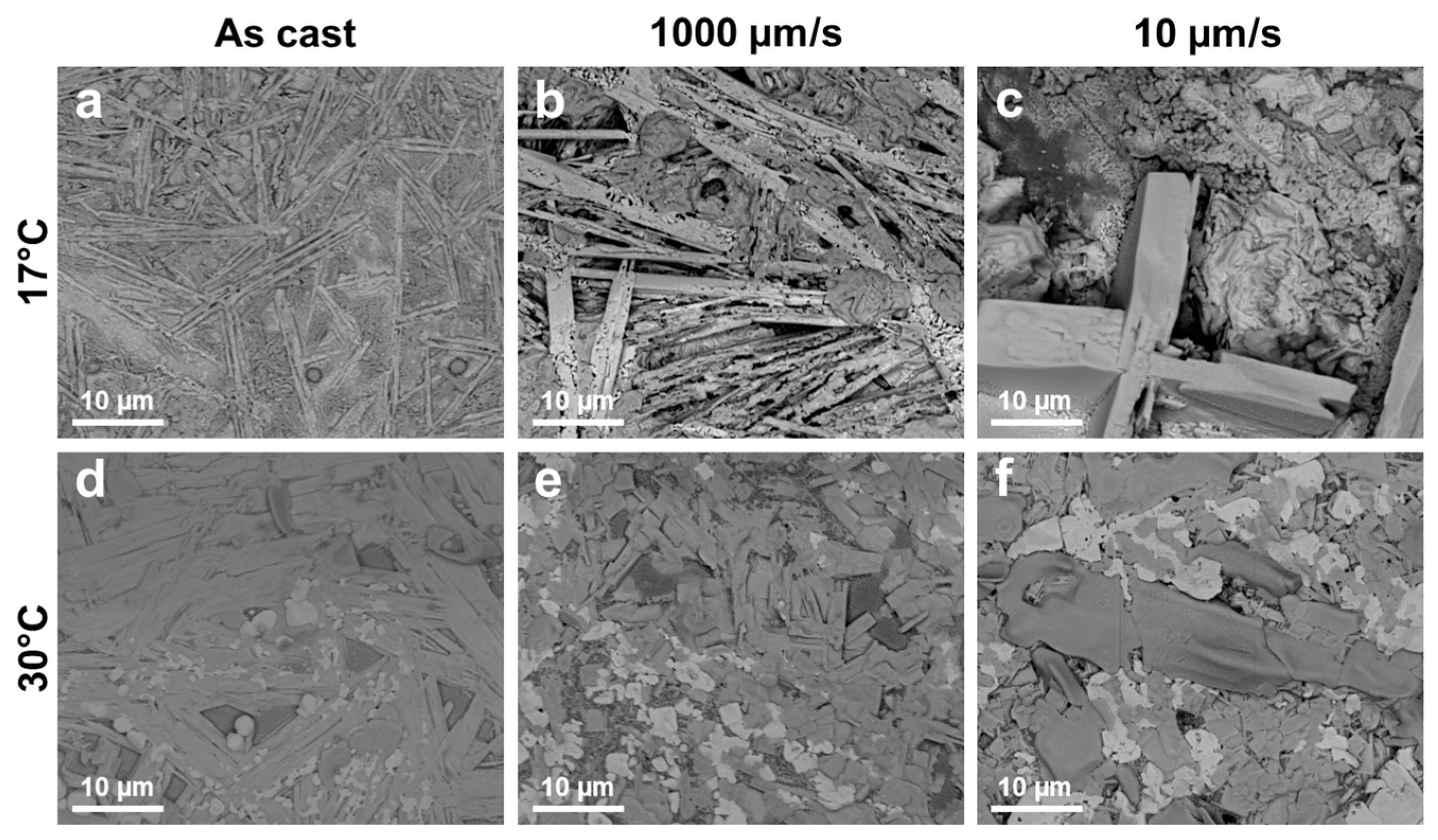
To better observe the differences that appeared between all the above-mentioned crystals, we have zoomed in on some of the regions presented in Figure 2 and assembled them in Figure 3. We could observe right away that the needle-like and cross-shaped perovskite crystals that formed at 17 °C had a three-dimensional (3D) shape (see Figure 3a–c and Figure S2 in the Supplementary Materials), often with well-defined, extremely sharp edges. This was not the case for the perovskite crystals generated at 30 °C, as such crystals exhibited a more rectangular shape that was much less prominent along the vertical direction (rather quasi-2D crystals; see Figure 3d–f and Figure S3 in the Supplementary Materials). Moreover, the rectangular shapes of these crystals often displayed rather curved “corners” (Figure 3f and Figure S3c), which was not the case for their analogs obtained at the lower processing temperature.
Recently, we have succeeded in producing hybrid lead halide CH3NH3PbI3-xClx perovskite crystals by injecting small volumes of the same perovskite precursor ink that we used in this study into open-air Teflon rings and by heating the resulting ensemble to a desired processing temperature. Experiments have shown that the morphology of perovskite crystals was highly dependent on the processing temperature [54]. This information, coupled with all data presented above, indicated that perovskite crystals could be also generated at temperatures lower than 17 °C. Because the CSA tool is limited by design to functioning at processing temperatures ranging only between 15 °C and 35 °C [67], we have decided to further utilize the drop-casting technique in order to eventually produce perovskite crystals at a lower temperature. For that, we dropped perovskite ink on two glass substrates kept at 0 °C and 30 °C, respectively, and waited for the solvent to evaporate. While at the latter temperature, we expected the resulting perovskite structures to be at some extent comparable with those presented in Figure 2d, the structures that would be generated at the former temperature, when the rate of solvent evaporation is dramatically reduced, were expected to be larger and eventually fewer.
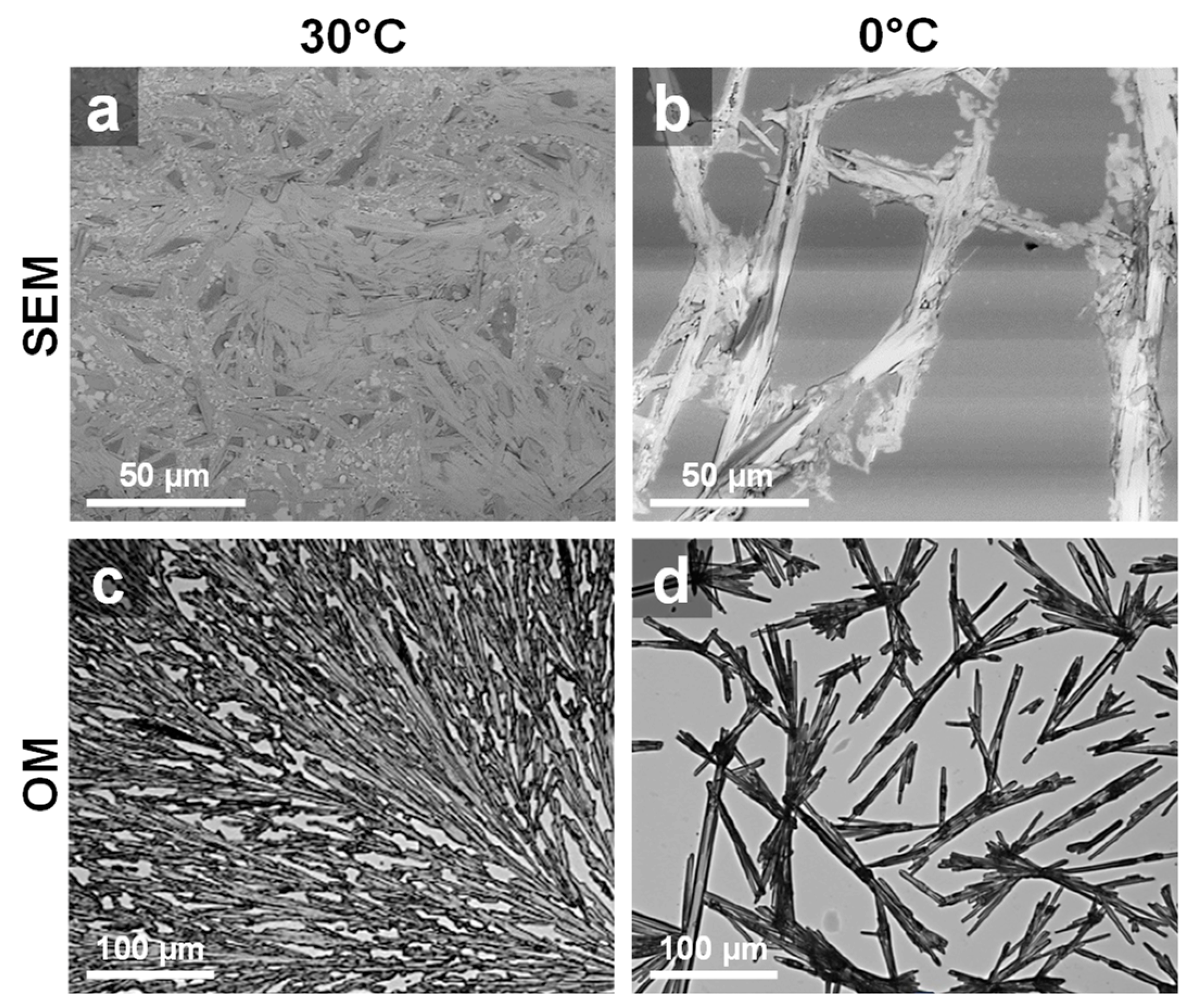
Indeed, perovskite crystals obtained at 30 °C resembled those obtained using the spin coating method at the same temperature (compare Figure 4a with Figure 2d). This suggested that the spin coating process was not sufficient to induce the complete evaporation of the solvent, and the process of perovskite crystal formation continued afterward, similarly to the process that led to perovskite crystals in the film obtained by drop casting. This statement was further confirmed by investigating a freshly spin-coated perovskite film under the optical microscope (or naked eye) and by observing that it was still wet and possibly undergoing further crystallization.
Instead, structures obtained by drop casting at 0 °C were fewer, often interconnected and much larger, and appeared to comprise coalesced/bundled yet much smaller needle-like perovskite crystals (Figure 4b). These aggregated crystalline structures were further observed to be displaying elongated, but rather irregular shapes, as can be observed in the optical microscopy (OM) image shown in Figure 4d. Moreover, such structures were consistently separated by regions of rather “naked” substrate (note that we cannot fully exclude the existence of a very thin perovskite layer that could not be detected under the optical microscope after the gentle scratching of the film). In comparison, perovskite structures generated by drop casting at 30 °C were much smaller and denser and were covering the substrate well (only rather small “naked” regions were detected in Figure 4c).
Finally, we dedicate the last section of this study to the emission properties displayed by the obtained hybrid lead halide CH3NH3PbI3-xClx perovskite crystalline structures. In order to infer the most appropriate excitation wavelength for such films, first we have measured the absorption spectrum of a dried perovskite film deposited using the spin coating method. As can be observed in Figure 5a, the perovskite film presented a clear absorption peak at a wavelength of about 300 nm, while at a longer wavelength of 355 nm, another less prominent peak could further be noticed. These results are in good agreement with other reports published in the literature on hybrid CH3NH3PbI3-xClx perovskites [74]. Therefore, we decided to employ the wavelength of 300 nm as the excitation wavelength.
Figure 5b summarizes all PL spectra recorded for perovskite films made using the CSA method at various deposition speeds (note here that PL spectra were recorded 45 min after the preparation of films). Straightforwardly, one can observe that films of this hybrid lead halide perovskite system emitted light at a wavelength ranging between about 700 and 815 nm, in agreement with previous reports available in the literature [74]. Moreover, the shape of PL spectra was different. While the films prepared at high CSA deposition speeds (i.e., 1000 µm/s and 500 µm/s) displayed a dominant emission peak at 798 nm, the films prepared at lower CSA deposition speeds (i.e., 100 µm/s, 50 µm/s and 10 µm/s) exhibited a dominant peak at a shorter wavelength of about 760 nm.
Unfortunately, each CSA deposition speed determines a unique film thickness (i.e., a lower CSA deposition speed typically leads to thicker films). Thus, it was not possible to further compare the PL intensities in Figure 5b, as one would not know whether these intensities were due to structural changes induced in the films by different CSA deposition speeds or just due to the different amount of perovskite material existing in films of unequal thicknesses, or possibly both. We nonetheless hypothesized that the predominant changes in the PL intensity were rather due to induced structural changes, i.e., due to crystallization of the perovskite material upon different CSA processing conditions. This statement was further sustained by the fact that all PL spectra shown in Figure 5b were acquired only 45 min after the fabrication of perovskite films via CSA. While this time was rather sufficient for thinner films (obtained at higher deposition speeds) to dry, it was not long enough for thicker films obtained at lower CSA deposition speeds to completely dry (the thicker films could undergo crystallization beyond the 45 min time and could further suffer changes in their emission properties).
To prove the above hypothesis, we have followed in time the emission of a perovskite film obtained at a CSA deposition speed of 100 µm/s. In Figure 5c, one can clearly see that right after the termination of the CSA procedure, the only observable emission peak was the dominant peak at 798 nm. No spectral changes were recorded in the next 5, 10 and 30 min while the film continued to dry. Nonetheless, important spectral changes appeared when 60 min had passed after the termination of the CSA procedure. At this point, while the perovskite film was still drying, the PL spectrum displayed the dominant peak, of significantly increased intensity, at around 760 nm. The peak located at 798 nm, although it had also experienced an increase in intensity, had lost its dominance. After another 60 min, the perovskite film completely dried, and its PL spectrum was dominated by the large peak located at 760 nm, with only a weak shoulder being visible at 798 nm. A further waiting beyond 120 min (i.e., 150 and 180 min) did not lead to other spectral changes, clearly indicating that the drying of the film and, thus, the crystallization process were both completed about 2 h after the termination of the CSA procedure.
In summary, the above results indicate that at the beginning, when the crystallization process was induced during the CSA procedure, the PL properties were dictated by the precursor nature of the perovskite ink. However, once the crystallization proceeded within the CSA-cast fresh film, the newly developed perovskite crystals dictated the resulting PL properties more and more. This statement was further strengthened when comparing the PL spectrum of a freshly spin-coated perovskite film with the PL spectrum of the same film after its complete drying (Figure S4 in the Supplementary Materials). In this case too, the final PL intensity was higher and centered above 760 nm. Nonetheless, the appearance of the dominant peak above 760 nm in the PL spectrum of the freshly coated film indicated that the film was already undergoing crystallization upon the highly dynamic spin coating process.

4. Conclusions

In this study, we have shown that the CSA technique could be manipulated to reach low solvent evaporation rate experimental conditions and to produce large 3D cross-like and needle-like hybrid lead halide CH3NH3PbI3-xClx perovskite crystals. Such crystals were shown to form only in films fabricated at a rather low CSA deposition speed and using a low processing temperature of 17 °C. Films produced using a higher CSA deposition speed and/or higher processing temperatures exhibited a morphology comprised of only smaller 3D needle-like and quasi-2D rectangular perovskite crystals. Moreover, the obtained perovskite crystals were shown to emit more light, but at a shorter wavelength, than the uncrystallized analog material. These results could be further used when developing various perovskite-based photodetectors, sensors or energy devices such as solar cells, LEDs or field-effect transistors.

Supplementary Materials

The following supporting information can be downloaded at: https://www.mdpi.com/article/10.3390/coatings13061130/s1. Figure S1. SEM micrograph depicting a large hybrid lead halide CH3NH3PbI3–xClx perovskite crystals obtained via CSA at 17 °C and a deposition speed of only 10 µm/s; Figure S2. SEM micrographs depicting hybrid lead halide perovskite CH3NH3PbI3–xClx films pre-pared at 17 °C by spin-coating (a) and CSA (b,c) at both high (i.e., 1000 µm/s) (b) and low (i.e., 10 µm/s) (c) deposition speeds; Figure S3. SEM micrographs depicting hybrid lead halide perovskite CH3NH3PbI3–xClx films pre-pared at 30 °C by spin-coating (a) and CSA (b,c) at both high (i.e., 1000 µm/s) (b) and low (i.e., 10 µm/s) (c) deposition speeds; Figure S4. PL spectra depicting the emission properties of a perovskite film freshly obtained by spin coating a perovskite solution priorly kept at 17 °C and after its complete drying (i.e., 120 min).

Author Contributions

I.P. and O.T.-B. contributed equally to this work by designing the concept of the paper, conducting the experimental investigation, and writing the original draft. A.V. performed the SEM measurements. I.B. and L.D. supervised I.P. and O.T.-B. and edited the final manuscript. All authors have read and agreed to the published version of the manuscript.

Funding

This study was financed by the Ministry of Research, Innovation and Digitization through Program 1—Development of the national research & development system, Subprogram 1.2—Institutional performance—Projects that finance the RDI excellence, Contract No. 18PFE/30.12.2021. This work was also implemented through the Core Program within the National Research Development and Innovation Plan 2022–2027, with the support of MCID, project No. PN 23 05.

Institutional Review Board Statement

Not applicable.

Informed Consent Statement

Not applicable.

Data Availability Statement

The data presented in this study are available on request from the corresponding author.

Conflicts of Interest

The authors declare no conflict of interest.

References

  1. Zheng, Z.; Zhang, S. The Importance of Governance Efficiency in Environmental Policy Research in Energy Shortage Period. J. Sustain. Bus. Econ. 2022, 5, 25. [Google Scholar] [CrossRef]
  2. Tao, J.; Waqas, M.; Ali, M.; Umair, M.; Gan, W.; Haider, H. Pakistan’s Electrical Energy Crises, a Way Forward towards 50% of Sustain Clean and Green Electricity Generation. Energy Strategy Rev. 2022, 40, 100813. [Google Scholar] [CrossRef]
  3. Glazer, A.M. Simple Ways of Determining Perovskite Structures. Acta Crystallogr. Sect. A 1975, 31, 756–762. [Google Scholar] [CrossRef] [Green Version]
  4. Maafa, I.M. All-Inorganic Perovskite Solar Cells: Recent Advancements and Challenges. Nanomaterials 2022, 12, 1651. [Google Scholar] [CrossRef] [PubMed]
  5. Li, H.; Zhang, W. Perovskite Tandem Solar Cells: From Fundamentals to Commercial Deployment. Chem. Rev. 2020, 120, 9835–9950. [Google Scholar] [CrossRef]
  6. Al-Asbahi, B.A.; Qaid, S.M.H.; Hezam, M.; Bedja, I.; Ghaithan, H.M.; Aldwayyan, A.S. Effect of Deposition Method on the Structural and Optical Properties of CH3NH3PbI3 Perovskite Thin Films. Opt. Mater. 2020, 103, 109836. [Google Scholar] [CrossRef]
  7. Liu, Y.; Chen, P.-A.; Hu, Y. Recent Developments in Fabrication and Performance of Metal Halide Perovskite Field-Effect Transistors. J. Mater. Chem. C 2020, 8, 16691–16715. [Google Scholar] [CrossRef]
  8. Abiram, G.; Thanihaichelvan, M.; Ravirajan, P.; Velauthapillai, D. Review on Perovskite Semiconductor Field–Effect Transistors and Their Applications. Nanomaterials 2022, 12, 2396. [Google Scholar] [CrossRef]
  9. Guo, J.; Liu, Y.; Chen, P.; Qiu, X.; Wei, H.; Xia, J.; Chen, H.; Zeng, Z.; Liao, L.; Hu, Y. Tuning the Electrical Performance of 2D Perovskite Field-Effect Transistors by Forming Organic Semiconductor/Perovskite van Der Waals Heterojunctions. Adv. Electron. Mater. 2022, 8, 2200148. [Google Scholar] [CrossRef]
  10. Li, Z.; Chen, Z.; Yang, Y.; Xue, Q.; Yip, H.-L.; Cao, Y. Modulation of Recombination Zone Position for Quasi-Two-Dimensional Blue Perovskite Light-Emitting Diodes with Efficiency Exceeding 5%. Nat. Commun. 2019, 10, 1027. [Google Scholar] [CrossRef] [Green Version]
  11. Lu, J.; Wei, Z. The Strategies for Preparing Blue Perovskite Light-Emitting Diodes. J. Semicond. 2020, 41, 051203. [Google Scholar] [CrossRef]
  12. Manser, J.S.; Christians, J.A.; Kamat, P.V. Intriguing Optoelectronic Properties of Metal Halide Perovskites. Chem. Rev. 2016, 116, 12956–13008. [Google Scholar] [CrossRef]
  13. Chouhan, L.; Ghimire, S.; Subrahmanyam, C.; Miyasaka, T.; Biju, V. Synthesis, Optoelectronic Properties and Applications of Halide Perovskites. Chem. Soc. Rev. 2020, 49, 2869–2885. [Google Scholar] [CrossRef]
  14. Savill, K.J.; Ulatowski, A.M.; Herz, L.M. Optoelectronic Properties of Tin–Lead Halide Perovskites. ACS Energy Lett. 2021, 6, 2413–2426. [Google Scholar] [CrossRef] [PubMed]
  15. Dong, H.; Ran, C.; Gao, W.; Li, M.; Xia, Y.; Huang, W. Metal Halide Perovskite for Next-Generation Optoelectronics: Progresses and Prospects. eLight 2023, 3, 3. [Google Scholar] [CrossRef]
  16. Cho, Y.; Jung, H.R.; Jo, W. Halide Perovskite Single Crystals: Growth, Characterization, and Stability for Optoelectronic Applications. Nanoscale 2022, 14, 9248–9277. [Google Scholar] [CrossRef] [PubMed]
  17. Snaith, H.J. Present Status and Future Prospects of Perovskite Photovoltaics. Nat. Mater. 2018, 17, 372–376. [Google Scholar] [CrossRef]
  18. Guo, Z.; Jena, A.K.; Kim, G.M.; Miyasaka, T. The High Open-Circuit Voltage of Perovskite Solar Cells: A Review. Energy Environ. Sci. 2022, 15, 3171–3222. [Google Scholar] [CrossRef]
  19. Isikgor, F.H.; Zhumagali, S.; Merino, L.V.T.; De Bastiani, M.; McCulloch, I.; De Wolf, S. Molecular Engineering of Contact Interfaces for High-Performance Perovskite Solar Cells. Nat. Rev. Mater. 2022, 8, 89–108. [Google Scholar] [CrossRef]
  20. Badrooj, M.; Jamali-Sheini, F.; Torabi, N. Zn-Doped Pb/Sn Hybrid Perovskite Solar Cells: Towards High Photovoltaic Performance. Sol. Energy 2022, 236, 63–74. [Google Scholar] [CrossRef]
  21. Chen, Z.-Y.; Huang, N.-Y.; Xu, Q. Metal Halide Perovskite Materials in Photocatalysis: Design Strategies and Applications. Coord. Chem. Rev. 2023, 481, 215031. [Google Scholar] [CrossRef]
  22. Zhang, H.; Ji, X.; Yao, H.; Fan, Q.; Yu, B.; Li, J. Review on Efficiency Improvement Effort of Perovskite Solar Cell. Sol. Energy 2022, 233, 421–434. [Google Scholar] [CrossRef]
  23. Aftab, A.; Ahmad, M.I. A Review of Stability and Progress in Tin Halide Perovskite Solar Cell. Sol. Energy 2021, 216, 26–47. [Google Scholar] [CrossRef]
  24. Kim, J.Y.; Lee, J.-W.; Jung, H.S.; Shin, H.; Park, N.-G. High-Efficiency Perovskite Solar Cells. Chem. Rev. 2020, 120, 7867–7918. [Google Scholar] [CrossRef] [PubMed]
  25. Kojima, A.; Teshima, K.; Shirai, Y.; Miyasaka, T. Organometal Halide Perovskites as Visible-Light Sensitizers for Photovoltaic Cells. J. Am. Chem. Soc. 2009, 131, 6050–6051. [Google Scholar] [CrossRef]
  26. Min, H.; Lee, D.Y.; Kim, J.; Kim, G.; Lee, K.S.; Kim, J.; Paik, M.J.; Kim, Y.K.; Kim, K.S.; Kim, M.G.; et al. Perovskite Solar Cells with Atomically Coherent Interlayers on SnO2 Electrodes. Nature 2021, 598, 444–450. [Google Scholar] [CrossRef]
  27. Chen, B.; Yu, Z.J.; Manzoor, S.; Wang, S.; Weigand, W.; Yu, Z.; Yang, G.; Ni, Z.; Dai, X.; Holman, Z.C.; et al. Blade-Coated Perovskites on Textured Silicon for 26%-Efficient Monolithic Perovskite/Silicon Tandem Solar Cells. Joule 2020, 4, 850–864. [Google Scholar] [CrossRef]
  28. Agresti, A.; Pazniak, A.; Pescetelli, S.; Di Vito, A.; Rossi, D.; Pecchia, A.; Auf der Maur, M.; Liedl, A.; Larciprete, R.; Kuznetsov, D.V.; et al. Titanium-Carbide MXenes for Work Function and Interface Engineering in Perovskite Solar Cells. Nat. Mater. 2019, 18, 1228–1234. [Google Scholar] [CrossRef] [Green Version]
  29. He, J.; Wang, S.; Li, X.; Zhang, F. Seeding Agents in Metal Halide Perovskite Solar Cells: From Material to Mechanism. ChemSusChem 2023, 16, e202202109. [Google Scholar] [CrossRef]
  30. Xiong, Z.; Chen, X.; Zhang, B.; Odunmbaku, G.O.; Ou, Z.; Guo, B.; Yang, K.; Kan, Z.; Lu, S.; Chen, S.; et al. Simultaneous Interfacial Modification and Crystallization Control by Biguanide Hydrochloride for Stable Perovskite Solar Cells with PCE of 24.4%. Adv. Mater. 2022, 34, 2106118. [Google Scholar] [CrossRef]
  31. Sharma, R.; Sharma, A.; Agarwal, S.; Dhaka, M.S. Stability and Efficiency Issues, Solutions and Advancements in Perovskite Solar Cells: A Review. Sol. Energy 2022, 244, 516–535. [Google Scholar] [CrossRef]
  32. Lee, D.-K.; Park, N.-G. Materials and Methods for High-Efficiency Perovskite Solar Modules. Sol. RRL 2022, 6, 2100455. [Google Scholar] [CrossRef]
  33. Liao, J.; Wang, M.; Kong, L.; Chen, J.; Wang, X.; Yan, H.; Huang, J.; Tu, C. Dual-Mode Optical Temperature Sensing Behavior of Double-Perovskite CaGdMgSbO6:Mn4+/Sm3+ Phosphors. J. Lumin. 2020, 226, 117492. [Google Scholar] [CrossRef]
  34. Li, L.; Ye, S.; Qu, J.; Zhou, F.; Song, J.; Shen, G. Recent Advances in Perovskite Photodetectors for Image Sensing. Small 2021, 17, 2005606. [Google Scholar] [CrossRef] [PubMed]
  35. Wu, W.; Lu, H.; Han, X.; Wang, C.; Xu, Z.; Han, S.; Pan, C. Recent Progress on Wavelength-Selective Perovskite Photodetectors for Image Sensing. Small Methods 2023, 7, 2201499. [Google Scholar] [CrossRef]
  36. Sun, T.; Chen, T.; Chen, J.; Lou, Q.; Liang, Z.; Li, G.; Lin, X.; Yang, G.; Zhou, H. High-Performance p–i–n Perovskite Photodetectors and Image Sensors with Long-Term Operational Stability Enabled by a Corrosion-Resistant Titanium Nitride Back Electrode. Nanoscale 2023, 15, 7803–7811. [Google Scholar] [CrossRef]
  37. Liu, Q.; Gao, S.; Xu, L.; Yue, W.; Zhang, C.; Kan, H.; Li, Y.; Shen, G. Nanostructured Perovskites for Nonvolatile Memory Devices. Chem. Soc. Rev. 2022, 51, 3341–3379. [Google Scholar] [CrossRef]
  38. Zheng, Y.; Luo, F.; Ruan, L.; Tong, J.; Yan, L.; Sun, C.; Zhang, X. A Facile Fabrication of Lead-Free Cs2NaBiI6 Double Perovskite Films for Memory Device Application. J. Alloys Compd. 2022, 909, 164613. [Google Scholar] [CrossRef]
  39. Li, H.; Wang, X.; Chu, H.; Yao, X. High Performance Resistive Memory Device Based on Highly Stable Layered CsPb2Br5 Perovskite Polymer Nanocomposite. J. Alloys Compd. 2022, 921, 166014. [Google Scholar] [CrossRef]
  40. Wang, H.; Xu, W.; Wei, Q.; Peng, S.; Shang, Y.; Jiang, X.; Yu, D.; Wang, K.; Pu, R.; Zhao, C.; et al. In-Situ Growth of Low-Dimensional Perovskite-Based Insular Nanocrystals for Highly Efficient Light Emitting Diodes. Light Sci. Appl. 2023, 12, 62. [Google Scholar] [CrossRef]
  41. Fakharuddin, A.; Gangishetty, M.K.; Abdi-Jalebi, M.; Chin, S.-H.; Bin Mohd Yusoff, A.R.; Congreve, D.N.; Tress, W.; Deschler, F.; Vasilopoulou, M.; Bolink, H.J. Perovskite Light-Emitting Diodes. Nat. Electron. 2022, 5, 203–216. [Google Scholar] [CrossRef]
  42. Yang, D.; Zhao, B.; Yang, T.; Lai, R.; Lan, D.; Friend, R.H.; Di, D. Toward Stable and Efficient Perovskite Light-Emitting Diodes. Adv. Funct. Mater. 2022, 32, 2109495. [Google Scholar] [CrossRef]
  43. Mei, X.; Jia, D.; Chen, J.; Zheng, S.; Zhang, X. Approaching High-Performance Light-Emitting Devices upon Perovskite Quantum Dots: Advances and Prospects. Nano Today 2022, 43, 101449. [Google Scholar] [CrossRef]
  44. Morgenstern, T.; Lampe, C.; Naujoks, T.; Jurow, M.; Liu, Y.; Urban, A.S.; Brütting, W. Elucidating the Performance Limits of Perovskite Nanocrystal Light Emitting Diodes. J. Lumin. 2020, 220, 116939. [Google Scholar] [CrossRef]
  45. Zhang, L.; Miao, J.; Li, J.; Li, Q. Halide Perovskite Materials for Energy Storage Applications. Adv. Funct. Mater. 2020, 30, 2003653. [Google Scholar] [CrossRef]
  46. Tambwe, K.; Ross, N.; Baker, P.; Bui, T.-T.; Goubard, F. Humidity Sensing Applications of Lead-Free Halide Perovskite Nanomaterials. Materials 2022, 15, 4146. [Google Scholar] [CrossRef]
  47. George, K.J.; Halali, V.V.; Sanjayan, C.G.; Suvina, V.S.; Sakar, M.; Balakrishna, R.G. Perovskite Nanomaterials as Optical and Electrochemical Sensors. Inorg. Chem. Front. 2020, 7, 2702–2725. [Google Scholar] [CrossRef]
  48. Blancon, J.C.; Even, J.; Stoumpos, C.C.; Kanatzidis, M.G.; Mohite, A.D. Semiconductor Physics of Organic–Inorganic 2D Halide Perovskites. Nat. Nanotechnol. 2020, 15, 969–985. [Google Scholar] [CrossRef]
  49. Ricciardulli, A.G.; Yang, S.; Smet, J.H.; Saliba, M. Emerging Perovskite Monolayers. Nat. Mater. 2021, 20, 1325–1336. [Google Scholar] [CrossRef]
  50. Kim, E.-B.; Akhtar, M.S.; Shin, H.-S.; Ameen, S.; Nazeeruddin, M.K. A Review on Two-Dimensional (2D) and 2D-3D Multidimensional Perovskite Solar Cells: Perovskites Structures, Stability, and Photovoltaic Performances. J. Photochem. Photobiol. C Photochem. Rev. 2021, 48, 100405. [Google Scholar] [CrossRef]
  51. Rothmann, M.U.; Kim, J.S.; Borchert, J.; Lohmann, K.B.; O’Leary, C.M.; Sheader, A.A.; Clark, L.; Snaith, H.J.; Johnston, M.B.; Nellist, P.D.; et al. Atomic-Scale Microstructure of Metal Halide Perovskite. Science 2020, 370, eabb5940. [Google Scholar] [CrossRef] [PubMed]
  52. Ma, C.; Park, N.-G. A Realistic Methodology for 30% Efficient Perovskite Solar Cells. Chem 2020, 6, 1254–1264. [Google Scholar] [CrossRef]
  53. Xie, Y.; Xue, Q.; Yip, H. Metal-Halide Perovskite Crystallization Kinetics: A Review of Experimental and Theoretical Studies. Adv. Energy Mater. 2021, 11, 2100784. [Google Scholar] [CrossRef]
  54. Petrovai, I.; Todor-Boer, O.; David, L.; Botiz, I. Growth of Hybrid Perovskite Crystals from CH3NH3PbI3-XClx Solutions Subjected to Constant Solvent Evaporation Rates. Materials 2023, 16, 2625. [Google Scholar] [CrossRef]
  55. Brooks, K.G.; Nazeeruddin, M.K. Laser Processing Methods for Perovskite Solar Cells and Modules. Adv. Energy Mater. 2021, 11, 2101149. [Google Scholar] [CrossRef]
  56. Bai, D.; Bian, H.; Jin, Z.; Wang, H.; Meng, L.; Wang, Q.; (Frank) Liu, S. Temperature-Assisted Crystallization for Inorganic CsPbI2Br Perovskite Solar Cells to Attain High Stabilized Efficiency 14.81%. Nano Energy 2018, 52, 408–415. [Google Scholar] [CrossRef]
  57. Ye, T.; Sun, X.; Zhang, X.; Hao, S. Recent Advances of Cu-Based Hole Transport Materials and Their Interface Engineering Concerning Different Processing Methods in Perovskite Solar Cells. J. Energy Chem. 2021, 62, 459–476. [Google Scholar] [CrossRef]
  58. Sánchez, S.; Vallés-Pelarda, M.; Alberola-Borràs, J.-A.; Vidal, R.; Jerónimo-Rendón, J.J.; Saliba, M.; Boix, P.P.; Mora-Seró, I. Flash Infrared Annealing as a Cost-Effective and Low Environmental Impact Processing Method for Planar Perovskite Solar Cells. Mater. Today 2019, 31, 39–46. [Google Scholar] [CrossRef]
  59. Li, X.; Bi, D.; Yi, C.; Décoppet, J.-D.; Luo, J.; Zakeeruddin, S.M.; Hagfeldt, A.; Grätzel, M. A Vacuum Flash–Assisted Solution Process for High-Efficiency Large-Area Perovskite Solar Cells. Science 2016, 353, 58–62. [Google Scholar] [CrossRef]
  60. Swartwout, R.; Hoerantner, M.T.; Bulović, V. Scalable Deposition Methods for Large-area Production of Perovskite Thin Films. Energy Environ. Mater. 2019, 2, 119–145. [Google Scholar] [CrossRef] [Green Version]
  61. Zhang, Z.; Wei, D.; Xie, B.; Yue, X.; Li, M.; Song, D.; Li, Y. High Reproducibility of Perovskite Solar Cells via a Complete Spin-Coating Sequential Solution Deposition Process. Sol. Energy 2015, 122, 97–103. [Google Scholar] [CrossRef]
  62. Bishop, J.E.; Smith, J.A.; Lidzey, D.G. Development of Spray-Coated Perovskite Solar Cells. ACS Appl. Mater. Interfaces 2020, 12, 48237–48245. [Google Scholar] [CrossRef]
  63. Wei, Z.; Chen, H.; Yan, K.; Yang, S. Inkjet Printing and Instant Chemical Transformation of a CH3NH3PbI3/Nanocarbon Electrode and Interface for Planar Perovskite Solar Cells. Angew. Chem. Int. Ed. 2014, 53, 13239–13243. [Google Scholar] [CrossRef]
  64. Yang, Z.; Chueh, C.-C.; Zuo, F.; Kim, J.H.; Liang, P.-W.; Jen, A.K.-Y. High-Performance Fully Printable Perovskite Solar Cells via Blade-Coating Technique under the Ambient Condition. Adv. Energy Mater. 2015, 5, 1500328. [Google Scholar] [CrossRef]
  65. Todor-Boer, O.; Petrovai, I.; Tarcan, R.; Vulpoi, A.; David, L.; Astilean, S.; Botiz, I. Enhancing Photoluminescence Quenching in Donor–Acceptor PCE11:PPCBMB Films through the Optimization of Film Microstructure. Nanomaterials 2019, 9, 1757. [Google Scholar] [CrossRef] [PubMed] [Green Version]
  66. Todor-Boer, O.; Petrovai, I.; Tarcan, R.; David, L.; Astilean, S.; Botiz, I. Control of Microstructure in Polymer: Fullerene Active Films by Convective Self-Assembly. Thin Solid Film. 2020, 697, 137780. [Google Scholar] [CrossRef]
  67. Botiz, I.; Codescu, M.-A.; Farcau, C.; Leordean, C.; Astilean, S.; Silva, C.; Stingelin, N. Convective Self-Assembly of π-Conjugated Oligomers and Polymers. J. Mater. Chem. C 2017, 5, 2513–2518. [Google Scholar] [CrossRef]
  68. Liu, H.; Liu, H.-R.; Yang, F.; Yang, J.-E.; Song, J.; Li, M.; Li, Z.; Tsoi, W.C.; Chinweokwu Eze, M.; Liu, Z.-Y.; et al. π-Conjugated Small Molecules Enable Efficient Perovskite Growth and Charge-Extraction for High-Performance Photovoltaic Devices. J. Power Sources 2020, 448, 227420. [Google Scholar] [CrossRef]
  69. Song, D.; Heo, J.H.; Han, H.J.; You, M.S.; Im, S.H. Reproducible Formation of Uniform CH3NH3PbI3-xClx Mixed Halide Perovskite Film by Separation of the Powder Formation and Spin-Coating Process. J. Power Sources 2016, 310, 130–136. [Google Scholar] [CrossRef]
  70. Tanaka, H.; Ohishi, Y.; Oku, T. Fabrication and Characterization of the Copper Bromides-Added CH3NH3PbI3-xClx Perovskite Solar Cells. Synth. Met. 2018, 244, 128–133. [Google Scholar] [CrossRef]
  71. Thankaraj Salammal, S.; Panneerselvam, V.; Chinnakutti, K.K.; Manidurai, P.; Parasuraman, K. Highly Crystalline Methylammonium Lead Iodide Films: Phase Transition from Tetragonal to Cubic Structure by Thermal Annealing. J. Vac. Sci. Technol. A 2021, 39, 022801. [Google Scholar] [CrossRef]
  72. Eperon, G.E.; Burlakov, V.M.; Docampo, P.; Goriely, A.; Snaith, H.J. Morphological Control for High Performance, Solution-Processed Planar Heterojunction Perovskite Solar Cells. Adv. Funct. Mater. 2014, 24, 151–157. [Google Scholar] [CrossRef]
  73. Barrows, A.T.; Lilliu, S.; Pearson, A.J.; Babonneau, D.; Dunbar, A.D.F.; Lidzey, D.G. Monitoring the Formation of a CH3NH3PbI3-xClx Perovskite during Thermal Annealing Using X-ray Scattering. Adv. Funct. Mater. 2016, 26, 4934–4942. [Google Scholar] [CrossRef] [Green Version]
  74. Tan, Z.-K.; Moghaddam, R.S.; Lai, M.L.; Docampo, P.; Higler, R.; Deschler, F.; Price, M.; Sadhanala, A.; Pazos, L.M.; Credgington, D.; et al. Bright Light-Emitting Diodes Based on Organometal Halide Perovskite. Nat. Nanotechnol. 2014, 9, 687–692. [Google Scholar] [CrossRef]
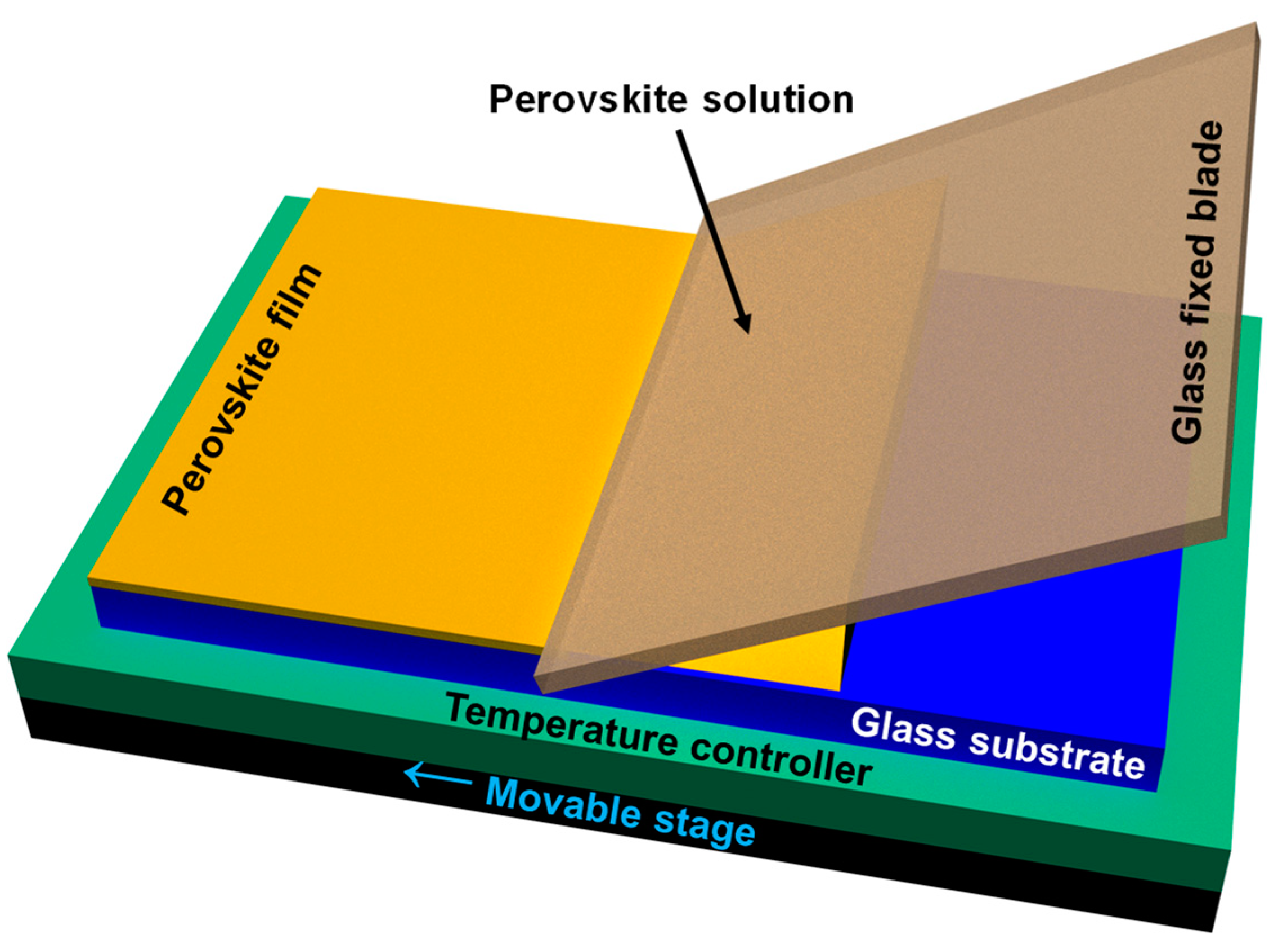
Figure 1. Schematic illustrating the CSA homemade experimental setup used to fabricate hybrid lead halide perovskite films.
Coatings 13 01130 g001
Figure 2. SEM micrographs depicting hybrid lead halide CH3NH3PbI3-xClx perovskite films prepared at two different temperatures by spin coating (a,d) and CSA (b,c,e,f) at both high (i.e., 1000 µm/s) (b,e) and low (i.e., 10 µm/s) (c,f) deposition speeds.
Coatings 13 01130 g002
Figure 3. Zoomed view of the SEM micrographs shown in Figure 2 and depicting hybrid lead halide CH3NH3PbI3-xClx perovskite crystals obtained at two different temperatures by spin coating (a,d) and CSA (b,c,e,f) at both high (i.e., 1000 µm/s) (b,e) and low (i.e., 10 µm/s) (c,f) deposition speeds.
Coatings 13 01130 g003
Figure 4. SEM (a,b) and OM (c,d) images of CH3NH3PbI3-xClx perovskite films prepared by drop casting at 30 °C (a,c) and at 0 °C (b,d). Note that images were acquired for solid perovskite films, once the evaporation of the solvent at 30 °C and 0 °C was completed, i.e., after about 60 and 180 min, respectively.
Coatings 13 01130 g004
Figure 5. (a) Absorption spectrum of a dried hybrid lead halide CH3NH3PbI3-xClx perovskite film deposited by spin coating. (b) PL spectra taken 45 min after the preparation of perovskite films at 17 °C using the CSA method at various deposition speeds (b). PL spectra portraying the evolution in time of the emission properties of a perovskite film obtained at 17 °C using the CSA method at a deposition speed of 100 µm/s (c). All PL spectra were recorded by using an excitation wavelength of 300 nm.
Coatings 13 01130 g005
Disclaimer/Publisher’s Note: The statements, opinions and data contained in all publications are solely those of the individual author(s) and contributor(s) and not of MDPI and/or the editor(s). MDPI and/or the editor(s) disclaim responsibility for any injury to people or property resulting from any ideas, methods, instructions or products referred to in the content.