Article

Coatings Prepared by Electro-Spark Alloying with SHS Electrode Materials Based on Ti-B-Fe-AlN

1
Merzhanov Institute of Structural Macrokinetics and Materials Sciences, Russian Academy of Sciences, Akademika Osipyana 8, 142432 Chernogolovka, Russia
2
Kurnakov Institute of General and Inorganic Chemistry, Russian Academy of Sciences, Leninskii Prospekt 31, 119991 Moscow, Russia
3
Joint Research Center of Belgorod State National Research University “Technology and Materials”, Research Institute of Materials Science and Innovative Technology, Belgorod State National Research University, Pobeda 85, 308015 Belgorod, Russia
4
Science and Innovation Department, Center for High Technologies of the Belgorod State Technological University, Belgorod State Technological University Named after V.G. Shoukhov, Kostyukov 46, 308012 Belgorod, Russia
*
Author to whom correspondence should be addressed.
Coatings 2023, 13(7), 1264; https://doi.org/10.3390/coatings13071264
Submission received: 13 June 2023 / Revised: 7 July 2023 / Accepted: 11 July 2023 / Published: 18 July 2023

Abstract

:
In this work, the features of the phase composition, structures, and properties of coatings obtained on a high-speed steel substrate (steel R6M5) were studied. The coatings were prepared using the ESA method (electro-spark alloying). Electrode materials prepared through self-propagating high-temperature synthesis (SHS) based on (Ti-B-Fe)xAlN with the addition of nanosized AlN particles in the amount of x = 0.5, 10, 15 wt % were used as electrodes. The structure, phase composition, and physical and mechanical properties of the SHS electrode materials are reported. It was found that the coatings inherited the structure of the SHS electrode material and formed two characteristic zones for x = 0 and three zones for x = 5, 10, 15. The surface hardness of the substrate made of the high-speed steel R6M5 with the developed coatings was found to increase up to five times compared to the uncoated substrate. It was found that the wear resistance of the samples with the coating was four to six times higher than that of uncoated samples.

1. Introduction

Nowadays, metal-cutting tools made of high-speed steel are widely in demand in mass production, because the use of a combined tool made of various hard alloys, ceramics, and artificial superhard materials significantly increases the cost of production. Improving the performance of parts and tools subject to intense wear is an urgent task of mechanical engineering [1,2,3,4,5]. Well-known methods for modifying the surface of parts and tools include PVD [6,7,8,9,10,11,12], CVD [13,14,15], and directed energy deposition (DED) [16]. In addition, known methods include (1) self-lubricating coatings obtained by laser additive manufacturing technology for friction reduction [17]; (2) textured coatings operating without lubrication and obtained by laser technologies [18]; (3) composite ceramic coatings obtained by the method of electric arc surfacing [19]; and (4) plasma electrolytic oxidation, also called micro-arc oxidation [20]. These methods are widely used in industry but have a number of advantages and limitations.
To apply wear-resistant coatings on metal-cutting tools, the method of electro-spark alloying (ESA) has become widespread. This method makes it possible to perform multiple hardening of the tool surface, without any treatment of the tool before and after hardening [21,22,23,24,25,26,27,28,29]. The method is quite simple in organizing the process of applying protective coatings, and rather simple and small-sized equipment is used when performing it. This method makes it possible to apply protective coatings on parts with different geometries, including complex ones. Any metals and alloys with electrical conductivity can be used as materials for applying protective coatings. An important distinguishing feature of this method is the absence of significant heating of the substrate on which the protective coating is applied. This makes it possible to exclude the formation of heat-affected zones in the substrate, which lead to the formation of internal stresses, leading to cracking of the coating and reducing its physical and mechanical characteristics.
The efficiency of the ESA method in the deposition of protective coatings is based on the use of high-quality electrode materials [30,31]. These coatings are promising for application to metal-cutting tools made of the high-speed steel R6M5, an analog of HSS steel. This material has high wear-resistant characteristics and possesses resistance to corrosion and temperature fluctuations. A wide range of tools for domestic and industrial use (drills, taps, milling cutters, cutters, etc.) are made from this high-speed steel. In this article, high-speed R6M5 was chosen as the basis for applying electro-spark alloying coatings due to its prevalence and availability.
Recently, multicomponent electrode materials, including high-entropy and medium-entropy alloys, have attracted great scientific and practical interest [32,33,34]. To obtain these electrode materials, the following methods are used: powder metallurgy methods, mechanical alloying and high-temperature sintering, spark plasma sintering, etc. Three new methods, i.e., thermal spraying, electro-spark deposition technology, and magnetron sputtering, were noted [35], which are used to deposit high-entropy coatings. The authors [35] focused on the relationship between the structure and the properties of coatings obtained under the conditions of a particular method. The paper also noted that the production of coatings using electro-spark deposition technology can fully realize the high-entropy effect of multicomponent components and can also lead to the formation of solid solution phases with a simple body-centered cubic structure or a face-centered cubic structure. The fine grains formed can lead to solid solution strengthening, which leads to an improvement in mechanical characteristics. Based on the analysis of the obtained results, the authors conclude that the structure and quality of the developed coatings completely depend on the parameters of each method that need to be optimized.
Free SHS compression [36,37,38] and SHS extrusion are promising methods for obtaining compact electrode materials. One of the promising methods for obtaining ceramic and cermet electrode materials used in electro-spark alloying is the SHS extrusion method [39,40,41,42]. The method is based on a combination of combustion processes in the mode of self-propagating high-temperature synthesis [43,44,45] and subsequent high-temperature shear deformation. The combination of these processes makes it possible to give combustion products a certain shape and size in one technological stage, which makes the process promising for obtaining electrode materials for ESA. It is also not unimportant that the duration of the process for obtaining electrode materials using the SHS compression and SHS extrusion methods is only tens of seconds, which makes the use of these methods very promising. In addition, due to the high combustion temperatures during the synthesis of the initial reagents (more than 1000 and up to 5000 °C), the requirements for the initial purity of the reagents used are reduced, especially in terms of the content of organic impurities.
Some of the in-demand electrode materials are materials based on titanium borides, which are superhard, heat-resistant, and refractory materials with a low thermal expansion coefficient [46,47,48,49,50]. However, these materials have high erosion resistance, and therefore, their use in pure form is limited. To solve this problem, a metal binder is additionally introduced into the material, which is selected taking into account the affinity with the substrate material. Since metal-cutting tools are predominantly made of alloy steel, iron is used as a metal binder. The authors [51] compared the structure and properties of SHS electrode materials based on titanium borides obtained by SHS extrusion, in which iron acted as a metal binder, and the same materials modified with aluminum nitride nanoparticles. For the composition without any modifier, it was found that the SHS electrode materials consisted of grains of titanium diboride located in the intermetallic TiFe matrix. The addition of nanosized AlN particles led to a decrease in the size of the structural components by up to 10 times; the formation of a new strengthening phase TiN and intermetallic compounds FeN, AlFe, and AlFe3; and, as a consequence, an increase in the physical and mechanical properties of SHS electrodes.
This work is devoted to the study of the structure, phase composition, and properties of protective coatings formed by the ESA method on a substrate made of high-speed steel (high-speed steel R6M5) using SHS electrode materials based on titanium borides modified and unmodified with AlN nanoparticles.

2. Materials and Methods

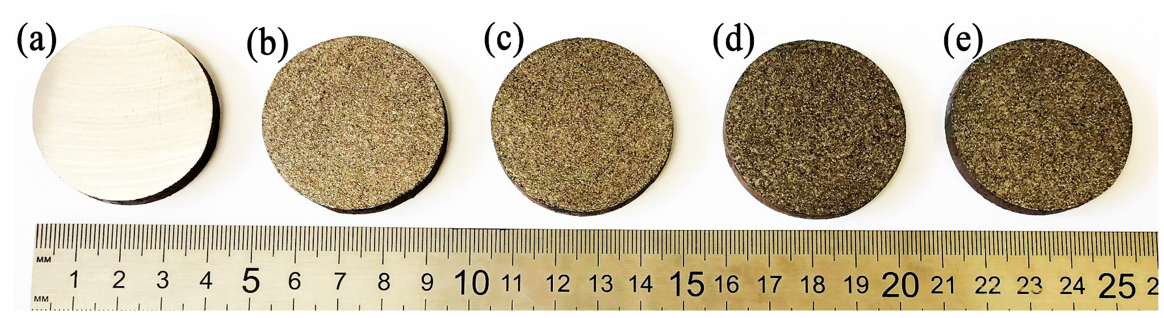
2.1. Objects of Study

In this work, the objects of study were protective coatings obtained by the ESA method using SHS electrode materials based on (Ti-B-Fe)xAlN with a varied number of AlN nanosized particles introduced: x = 0.5, 10, 15 wt %. The amount of AlN was selected based on the fact that the addition of less than 5 wt % AlN does not lead to significant structural and phase changes in extruded electrode materials. At the same time, when adding 15 wt % AlN, the changes are significant (grinding of grains of the boride phase, formation of TiN), and a further increase in the content of the additive leads to a critical drop in the exothermicity of the SHS reaction and, as a consequence, a decrease in the plasticity of the material, which makes the SHS extrusion process impossible. Therefore, the addition of 10 wt % AlN was chosen as an average value between 5 and 15 wt %.
The SHS electrode materials were obtained by SHS extrusion. The composition and properties of the SHS electrode materials are given in Table 1.
The high-speed steel R6M5 (Kirzhach Tool Factory, Kirzhach, Russia) was used as a substrate, from which metal-cutting tools (drills) were made. Samples were obtained from a bar of high-speed steel R6M5, which was mechanically cut into 5 mm thick discs. Table 2 shows the chemical composition of the steel used in this work. The analogs of this steel in other countries are the following: T11302 (USA), SKH51 (Japan), 3343 (England), Z85WDCV (France), HS6-5-2, S6-5-2S (Germany), SW7M (Poland).
Figure 1 shows the microstructure of the SHS electrode materials used in this work. The main strengthening phase for unmodified SHS electrode materials is grains of titanium diboride (dark-gray areas), 1.5–2 µm in size, located in the FeTi intermetallic binder (Table 3, Figure 2).
The addition of nanosized AlN particles to the initial mixture leads to the formation of a new strengthening TiN phase (rounded gray grains) with a size of about 2 μm as a result of SHS (Figure 1b–d). This phase is a hardening phase for developed coatings, which increases the hardness and wear resistance of coatings, and its presence in the coating has a positive effect. With an increase in the content of AlN nanoparticles, a significant decrease in the grain size of titanium diboride from 0.9–2 to 0.2–1.8 μm is observed. The decrease in the grain size of titanium diboride is explained by the fact that, when a nanomodifier in the form of dispersed AlN particles is added, the combustion temperature decreases because the heat released during the chemical reaction of titanium with boron is partially spent on the decomposition of AlN and is spent on further low-exothermic (taking into account the small fraction of nanoparticle additives) or endothermic reactions with the initial components and synthesis products. These factors limit the growth of titanium diboride grains [52,53]. The properties of the SHS electrode materials used in this work are reported in Table 1 and show that, with an increase in the number of AlN particles in the electrode material, its hardness increases and the electrical resistance decreases. The decrease in electrical resistance in the electrode material leads to an improvement in its erosive ability when applying a protective coating. This improves the quality of the applied coating and increases the productivity of the method itself.

2.2. ESA Coating

Protective coatings were applied using the ESA method on SE-5.01. The principle of the operation of the installation is based on a periodic electrical breakdown of the air space between the vibrating electrode and the surface to be treated. With each discharge, the electrode material being melted is transferred to the surface layer of the processed substrate. The surface of the substrates is preliminarily cleaned and degreased with alcohol. The properties and quality of the formed surface (uniformity, continuity, thickness, performance, etc.) depend on the discharge energy, Wp, which is determined by the formula: Wp = k∙(C∙U2/2), where C is the capacitance of the capacitor, U is the voltage on the capacitor, k is the coefficient that takes into account losses in the circuit (k = 0.8). In this work, the following ESA parameters were chosen: the capacitance of the capacitor bank was 140 μF, the output voltage was 51 V, and the oscillation frequency of the electromagnetic vibrator was 160 ± 10 Hz. Samples with a diameter of 30 and 40 mm and a thickness of 5 mm made of the high-speed steel R6M5 were used as model substrates. The coatings were applied in air at room conditions. The coated and uncoated samples are shown in Figure 3.

2.3. Sample Preparation

The samples were transversally cut, mechanically polished, and prepared by standard metallographic methods, namely, sectioning, mounting, and polishing. The samples were prepared by grinding with SiC sandpapers with various specifications (200, 500, 800, and 1000#), followed by polishing with a 1 μm diamond slurry according to the procedure recommended by the Struers company (Rotherham, UK) for ceramic coatings. The samples were cleaned with distilled water and dried at 100 °C for 3 h.

2.4. Methods

The microstructure and elemental composition of the samples were studied using a LEO 1450 VP electron-ion scanning microscope (Carl-Zeiss SMT AG, Oberkochen, Germany). X-ray powder diffraction studies of the surface of the samples were carried out on a DRON-3 diffractometer (NPP Burevestnik, St. Petersburg, Russia): materials with coatings were measured using FeKα radiation, whereas the SHS electrodes were measured using CuKα radiation. The PDF-2 database was used to define the phase composition of the coatings prepared. The microhardness of the coatings on the microsection was measured according to Russian State Standard GOST 9450-76 using a PMT-3 device (OJSC LOMO, St. Petersburg, Russia). A diamond pyramid with an apex angle of 136° and a square base was used as an indenter. The load value was 0.49 N for coated materials with a holding time of 10 s. The hardness of the SHS electrode materials was measured by the Vickers method (HV10/30) using a TN 500-01 (Time Group Inc., Beijing, China) hardness tester. The essence of the method lies in the introduction of a diamond indenter into the sample surface under the action of successively applied preliminary forces, F0, and main forces, F1. After that, the depth of penetration of the indenter was determined after the removal of the main force. The density of the samples was measured using the hydrostatic method, according to Russian State Standard GOST 20018-74. The electrical resistivity of the obtained samples was measured using the four-probe method. The microhardness of the coated samples was measured using a PMT-3 microhardness tester according to Russian State Standard GOST 9450-76. A diamond pyramid was used as an indenter; the load was 50 g at a holding time of 10 s.

2.5. Tribological Tests

The tribological evaluation of the samples under dry conditions was performed using a ball-on-disc tribometer that was manufactured by CSM Instruments (Peseux, Neuchatel, Switzerland) according to ASTM wear testing standard G-99. All tests were performed at 25 °C with a relative humidity of approximately 50%. A 6 mm diameter aluminum oxide (Al2O3) ball was used as a counter body. Samples from all the series were tested under a 15 N normal load, 0.10 m s–1 sliding speed, and a total sliding distance of 2000 m. During testing, the friction coefficient was recorded as a function of the sliding distance. The total wear volume was calculated by measuring the track cross-sectional area with a stylus profilometer (Taylor–Hobson, Leicester, UK) at ten different locations along the wear track. The ASTMG-99 standard determines the amount of wear by measuring the appropriate linear dimensions of both specimens (ball and disk) before and after the test [54].

3. Results and Discussion

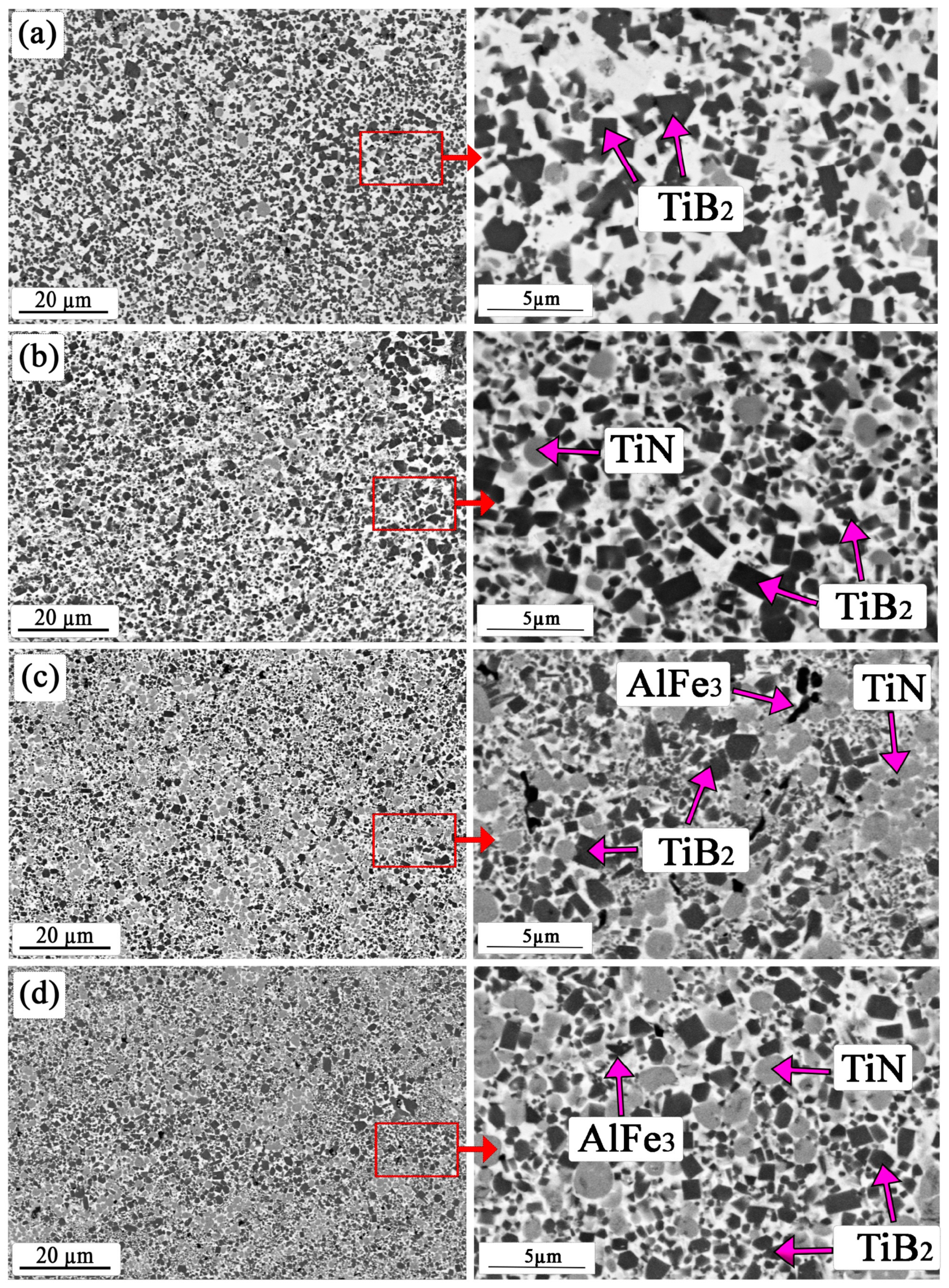
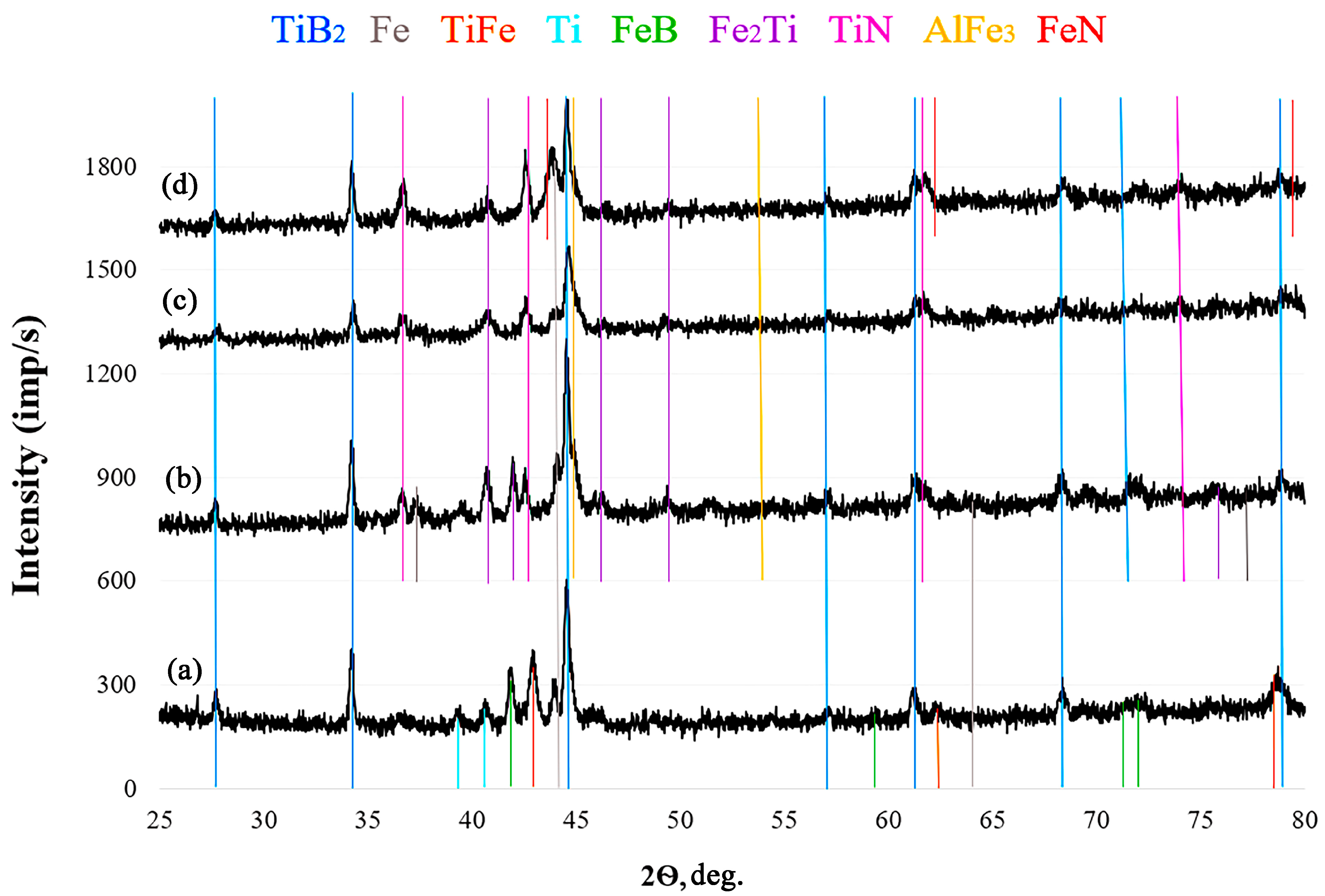
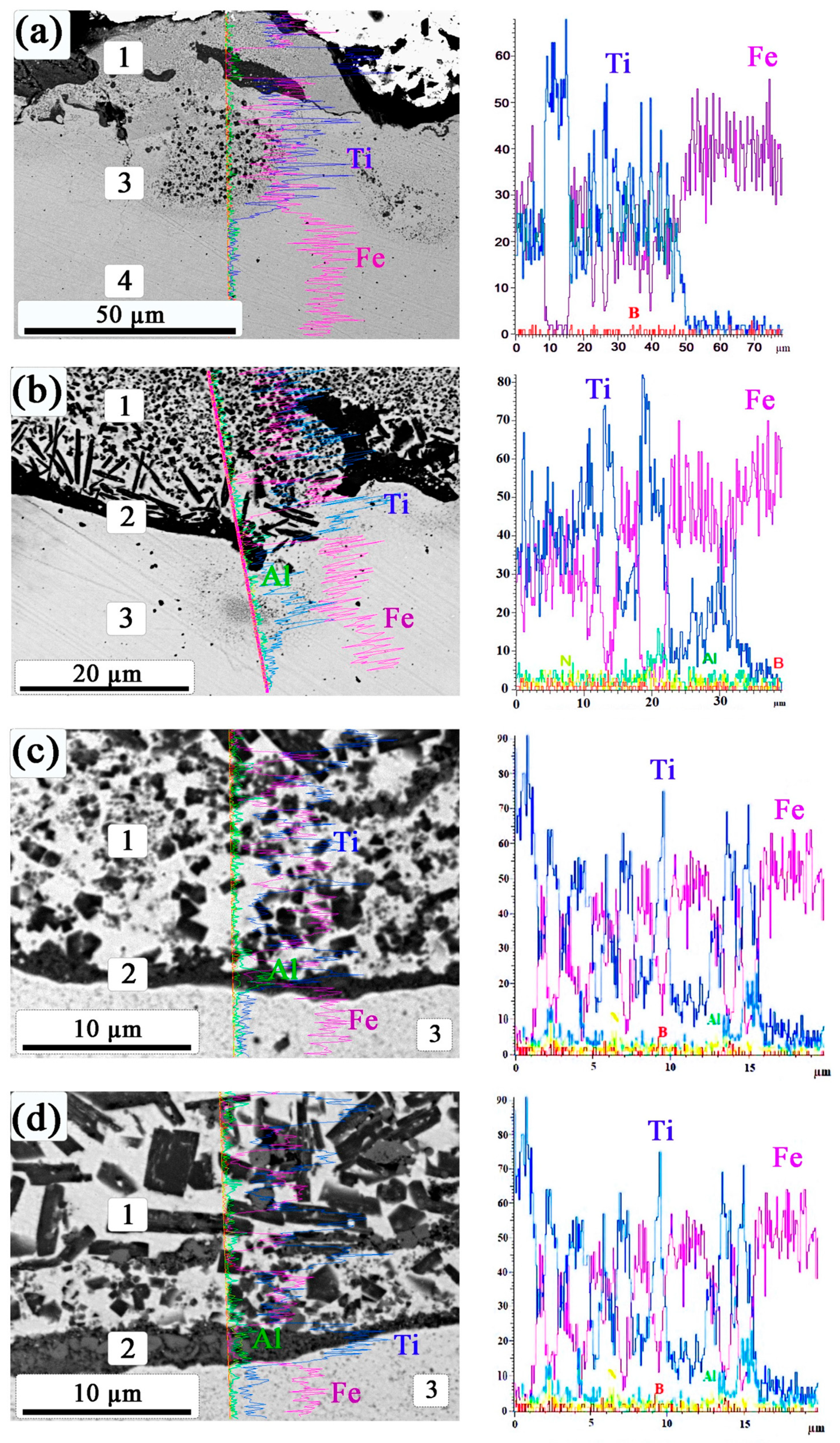
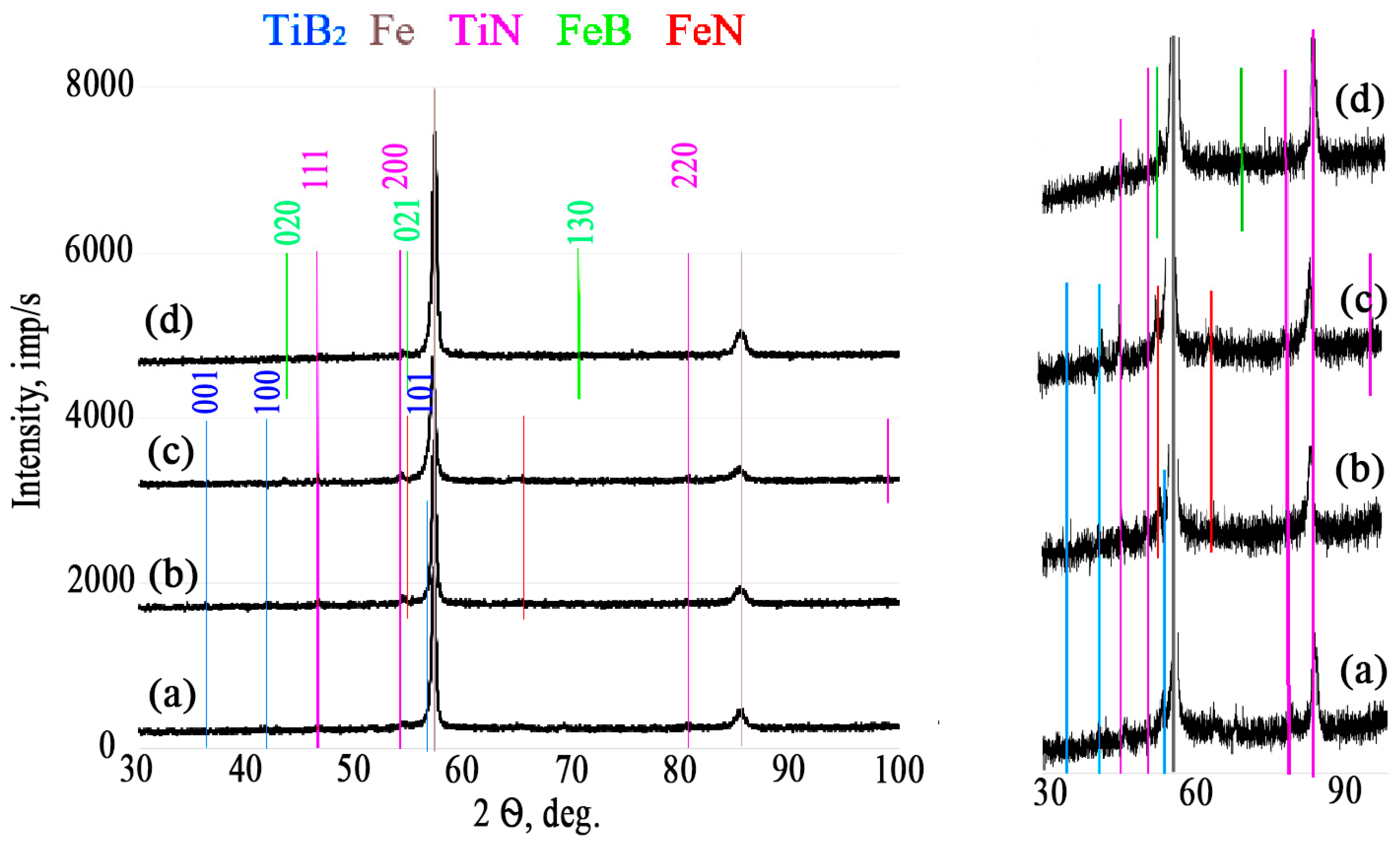
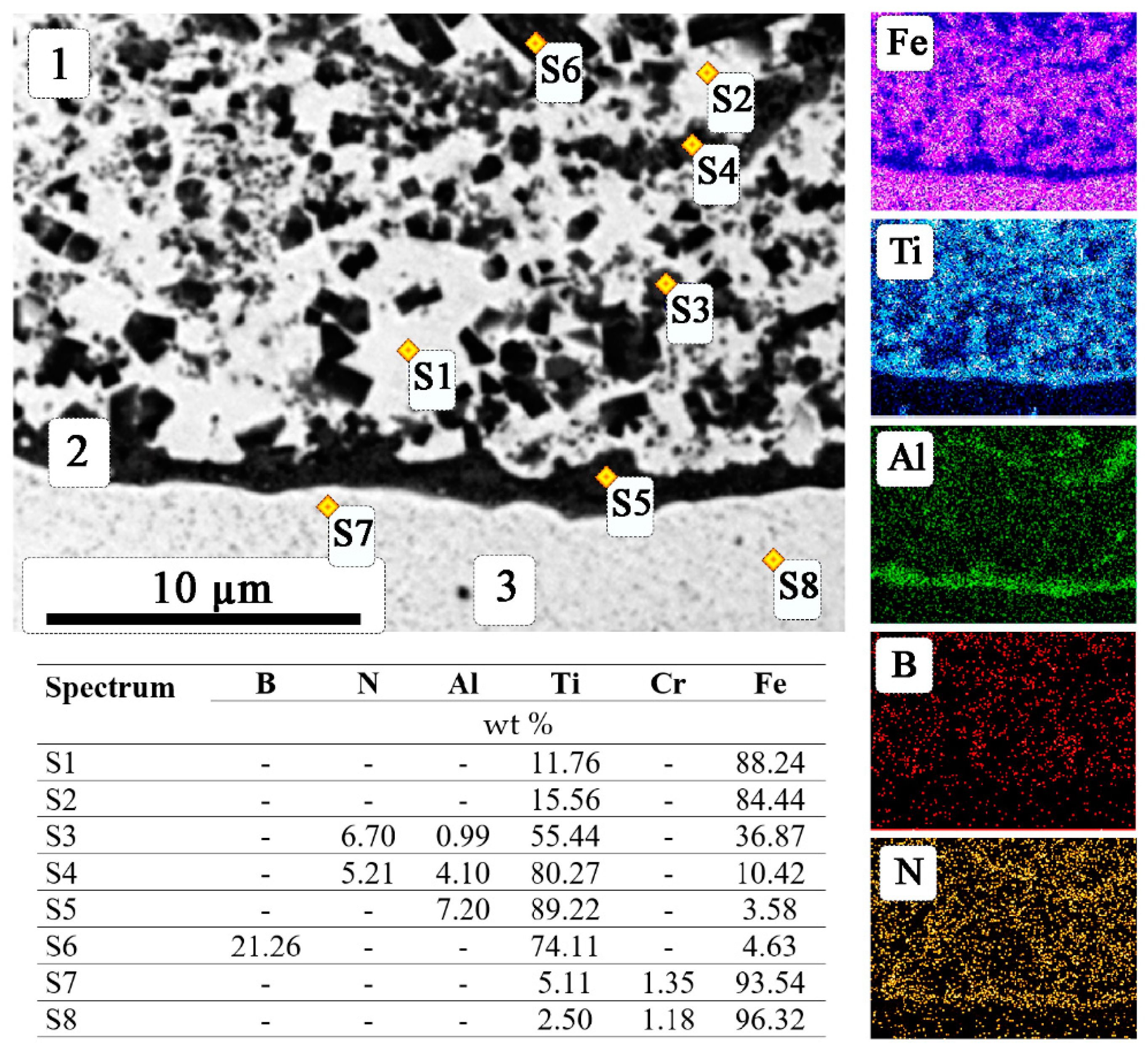
3.1. SEM and Energy-Dispersive X-ray Spectroscopy Data of Coatings

Figure 4 shows the results of SEM and the concentration curves of chemical elements along the selected line of the cross section of coatings obtained with SHS electrode materials of various compositions. It can be seen from the SEM results that the structure of the coated material in cross section had three characteristic zones: (1) coating, (2) border zone of the coating material with the substrate, and (3) transition layer. At the same time, it was found that, when using an unmodified SHS electrode (x = 0), the border zone was not formed. The cermet coating is a composite material consisting of an intermetallic matrix with hardening phases included in it.
The results of X-ray powder diffraction analysis of the surfaces of coatings obtained using the SHS electrode materials of the studied compositions are shown in Figure 5. It should be noted that, during the ESA process, the main strengthening phase of the TiB2 SHS electrode material was transferred to the substrate. The presence of the TiN phase was also observed in the coating, which was transferred from the SHS electrode (for nanomodified SHS electrode materials at x = 5; 10; 15) and additionally formed due to air-performed ESA. Thus, the deposition of coatings in air and with the use of SHS electrodes modified with AlN particles led to the formation of a new hardening TiN phase in the coating, which will have a positive effect on improving the physical and mechanical and tribological properties. If the ESA process with the studied SHS electrode materials is carried out in a nitrogen atmosphere, then the amount of the TiN nitride phase formed in the coating will increase significantly. This issue requires a separate study. The thickness of the resulting coatings was approximately 30–40 μm, which does not depend on the composition of the SHS electrode material used. A characteristic view of the coating obtained by the ESA method is shown in Figure 4a. It is also possible to distinguish the border zone based on Ti-Al-Fe (1.5–2 µm) and a transition layer (3–5 µm). Since the thickness of the resulting coatings did not exceed 40 μm and the main strengthening phases (TiB2, TiN) had a lower density than the substrate material (high-speed steel R6M5), the intensity of reflections of the phases of the coating material was much lower than the intensity of the Fe peaks; therefore, the main peaks assigned to iron were predominantly observed on X-ray powder diffraction patterns (Table 4, Figure 5).
At the boundary between the coating and the substrate, diffusion–convection mixing of the materials of the SHS electrode melted during ESA and the substrate surface was observed, which results in a transition zone (Figure 6). For all selected compositions and ESA modes, the height of the transition layer fell in the range 3–5 µm, while the coating height was 30–40 µm.
The most complete picture of the distribution of the formed phases in the coating can be obtained from the results of energy dispersive analysis of the coating cross section. As a model sample, a coating obtained with an SHS electrode material of the composition (Ti-B-Fe)15AlN was taken (Figure 6). Based on the data obtained from Figure 5 and Figure 6, it was found that the structure of the coating material was conditionally divided into three sections, a characteristic feature of each of them was a uniform distribution of strengthening phases (TiB2 and TiN) in the intermetallic matrix (mainly TiFe). The upper part (zone 1) of the coating included both small, dark-gray grains of irregular shape (1–3 μm) and large, dendrite grains (5–10 μm) of the TiB2 phase, as well as light-gray grains (0.5–3 µm) of TiN. As they moved away from the surface, the grains of the boride phase acquired a dendritic shape, 5–10 μm in length, and became oriented in the direction of cooling. This is explained by the significant heat removal to the substrate during electro-spark deposition. Further, in zone 2, adjacent to the substrate, a dark-gray region was observed, consisting of an intermetallic compound Ti-Al-Fe, in which dissolved nitrogen was present. The width of this zone does not exceed 1.5–2 µm and is typical only for nanomodified SHS electrodes. Based on X-ray powder diffraction and EDA data, the presence of compounds with aluminum on the surface of coatings was not detected; therefore, it can be argued that, during ESA, molten metals (especially aluminum) move under the action of gravity, subsequently crystallizing at the interface with the substrate. Zone 3 is a zone of convective–diffusive mixing of the molten material of the SHS electrode and the substrate, resulting in the so-called transition zone. The course of the process of diffusion of the coating material into the substrate causes a strong adhesive bond between the coating material and the substrate. Such a structure is typical for coatings deposited by all the studied compositions. Hence, it can be concluded that the coating material inherits the phase composition of the SHS electrode material, and the differences in the structure are related to the heat-removal conditions in different coating zones. The electrode material is transferred to the substrate with the inheritance of the phase composition and structure, with one exception associated with different heat-removal conditions. When coatings are applied, the morphology of TiB2 grains changes in the contact zone. The grains become more elongated in the direction of the substrate. In the upper layers of the coating, the grains of titanium diboride have a size similar to the grains in the original electrode.

3.2. Distribution of Microhardness in the Coating

The resulting cermet coating had a gradient distribution of microhardness along the height (Figure 7). In the near-surface zone, the maximum value of microhardness was achieved due to the largest quantity of hardening phases of TiB2 and TiN and their smaller size. As we approach the substrate material, the microhardness decreases because of a decrease in the concentration of strengthening phases and the formation of a transition zone between the coating and the substrate. The coatings obtained by nanomodified SHS electrode materials (Ti-B-Fe)xAlN (at x = 5, 10, 15) have a slightly higher microhardness than coatings obtained by unmodified SHS electrodes, which correlates with their microhardness values. As a result, the surface hardness of the R6M5 high-speed steel substrate increased by up to five times compared to the uncoated substrate. An increase in the surface hardness of the treated, high-speed steel R6M5 and good adhesion of the resulting coatings and substrate due to the diffusion–convection mechanism during ESA should lead to an increase in their tribological characteristics. The results obtained exceed the values of microhardness of coatings obtained by similar methods [55,56,57].

3.3. Tribological Test Results

The results of tribological tests of experimental samples with protective coatings and without them are shown in Table 5. As can be seen from the results of tribological tests given in Table 2, any of the options modifying the surface significantly increased the wear resistance of a sample made of the high-speed steel R6M5. An increase in surface hardness led to an increase in its wear resistance (Table 4). It has been established that the wear resistance index of the samples with coatings based on (Ti-B-Fe)xAlN, calculated according to the method in [40] was four to six times higher than that of an uncoated sample (Table 4). Consequently, the developed (Ti-B-Fe)xAlN coatings improved the tribological properties of the treated metal substrate and increased its wear resistance. It should be noted that, with an increase in surface hardness when using nanomodified SHS electrodes, the wear increases compared with the use of unmodified SHS electrodes. This is because wear products having a high hardness are involved in the friction zone during testing, thereby increasing the wear rate of the resulting coating. During the operation of a metal-cutting tool in real conditions, wear products will leave the cut zone, which will lead to an increase in the service life of a tool with increased hardness.
After tribological tests, a study was made of the contact surface of the friction pair: the sample and the counter body. Micrographs of the characteristic tracks on the surface of the samples and the typical wear spots of an aluminum oxide ball are shown in Figure 8. The width of the friction track on the surface of the high-speed steel R6M5 sample without a coating (Figure 8a) was higher than for samples with a surface modified by (Ti-B-Fe)xAlN coatings. An analysis of the friction track on the surface of the uncoated sample showed that it wore out intensively, and the transfer of material to the counter body was also recorded (Figure 8a). At the bottom of the friction track, tearing and scuffing were observed.
Micrographs of the friction surface of samples with (Ti-B-Fe)xAlN coatings show that their wear was characterized by directional plastic deformation (Figure 8b,d). The friction surfaces were longitudinal contact areas oriented in the direction of sliding and did not experience significant damage and changes. On the worn surface of samples with coatings, areas were fixed that differed in color from the color of the friction track. Generally, the appearance of these areas is associated with the morphology of the initial surface of the coatings and smoothing of the initial roughness (protrusions and depressions) in the process of hard contact of the counter body with the surface.

4. Conclusions

In this work, Ti-B-Fe coatings unmodified/modified with AlN nanoparticles on specimens of the high-speed steel R6M5 were formed by the method of electro-spark alloying using SHS electrode materials based on (Ti-B-Fe)xAlN (x = 0, 5, 10, 15 wt %). The main results can be summarized as follows:
(1) The formed coatings were a composite material that inherited the phase composition of the used SHS electrode and consisted of strengthening phases (TiB2 and TiN) located in the TiFe intermetallic matrix. In cross section, the coating had three characteristic zones: coating (30–40 µm), border zone based on Ti-Al-Fe (1.5–2 µm), and transition layer (3–5 µm). At the same time, it was found that, when using a non-nanomodified SHS electrode (x = 0), the border zone was not formed.
(2) The coatings obtained using nanomodified SHS electrode materials (Ti-B-Fe)xAlN (x = 5, 10, 15) had a slightly higher microhardness than coatings obtained using unmodified SHS electrodes. At the same time, the surface hardness of the substrate made of high-speed steel R6M5 with the developed coatings increased up to five times compared to the uncoated substrate.
(3) It was found that the wear resistance of the samples with the coating was four to six times higher than that of uncoated samples. Tribotechnical testing of the coatings showed that all coatings based on (Ti-B-Fe)xAlN, where x = 0, 5, 10, 15 wt % provided a high level of wear resistance. Comparative analysis of coating test results showed that the coatings showed comparable values of the wear factor under dry-friction conditions paired with an aluminum oxide indenter. Under the real operating conditions of a metal-cutting tool, in which wear products are removed from the friction zone, coatings obtained with SHS electrode materials modified with AlN particles will have less wear due to their higher hardness.
(4) Future work on this topic will be aimed at applying coatings with SHS electrode materials of the compositions under study on drills, cutters, and taps made of high-speed steel R6M5 and conducting further industrial testing.

Author Contributions

Conceptualization, A.S.; Data curation, P.B. and M.M.; Formal analysis, A.B.; Investigation, M.K., M.M., and V.S.; Methodology, A.S., M.M., and V.N.; Writing—original draft, A.B. and M.K.; Writing—review and editing, V.A. All authors have read and agreed to the published version of the manuscript.

Funding

This work was supported by the Ministry of Science and Higher Education of the Russian Federation as part of the State Assignment of the Merzhanov Institute of Structural Macrokinetics and Materials Sciences of the Russian Academy of Sciences (ISMAN) and the State Assignment of the Kurnakov Institute of General and Inorganic Chemistry of the Russian Academy of Sciences (IGIC RAS).

Institutional Review Board Statement

Not applicable.

Informed Consent Statement

Not applicable.

Data Availability Statement

Data sharing is not applicable to this article.

Acknowledgments

This work was carried out using the equipment of the Distribution Center for Collective Use of the Merzhanov Institute (ISMAN). The tribotechnical testing of coatings was carried out on the equipment of the Joint Research Center of Belgorod State National Research University “Technology and Materials”.

Conflicts of Interest

The authors declare no conflict of interest.

References

  1. Prasad, K.N.; Syed, I. Surface texturing and laser shock peening processes on high-speed steel tool for sustainable machining. Arab. J. Sci. Eng. 2022, 47, 8589–8600. [Google Scholar] [CrossRef]
  2. Okokpujie, I.P.; Bolu, C.A.; Ohunakin, O.S.; Akinlabi, E.T. Experimental study of the effect of TiN–Zn coated high-speed steel cutting tool on surface morphology of AL1060 alloy during machining operation. In Trends in Manufacturing and Engineering Management; Vijayan, S., Subramanian, N., Sankaranarayanasamy, K., Eds.; Lecture Notes in Mechanical Engineering; Springer: Singapore, 2021; pp. 637–647. [Google Scholar] [CrossRef]
  3. Qi, Y.; Nguyen, V.; Melkote, S.; Varenberg, M. Wear of mechanochemically treated high-speed steel cutting tools. J. Manuf. Sci. Eng. 2022, 144, 094505. [Google Scholar] [CrossRef]
  4. Yasin, J.; Selvakumar, S.; Mathan, K.P.; Sundaresan, R.; Arunraja, K.M. Experimental study of TiN, TiAlN and TiSiN coated high speed steel tool. Mater. Today Proc. 2022, 64, 1707–1710. [Google Scholar] [CrossRef]
  5. Aditharajan, A.; Radhika, N.; Saleh, B. Recent advances and challenges associated with thin film coatings of cutting tools: A critical review. Trans. IMF 2023, 101, 205–221. [Google Scholar] [CrossRef]
  6. Vardanyan, E.L.; Ramazanov, K.N.; Nagimov, R.S.; Nazarov, A.Y. Properties of intermetallic Ti-Al based coatings deposited on ultrafine grained martensitic steel. Surf. Coat. Technol. 2020, 389, 125657. [Google Scholar] [CrossRef]
  7. Ramazanov, K.N.; Vardanyan, E.L.; Mukhamadeev, V.R.; Mukhamadeev, I.R.; Maslov, A.A. Change in the chemical composition of a carbide tool with Ti-Al-N coating surface layers during machining. J. Surf. Investig. 2022, 16, 412–415. [Google Scholar] [CrossRef]
  8. Khusainov, Y.G.; Nikolaev, A.A.; Agzamov, R.D.; Ramazanov, K.N.; Tagirov, A.F. Influence of hydrogen content on ion nitriding of coarse-grained and ultrafine-grained VT6 titanium alloys. J. Phys. Conf. Ser. 2019, 1393, 012095. [Google Scholar] [CrossRef]
  9. Suhova, N.A.; Shekhtman, S.R.; Migranov, M.S. Synthesis of nanostructured composite coatings in arc discharge plasma. Lect. Notes Mech. Eng. 2019, 28, 1393–1399. [Google Scholar] [CrossRef]
  10. Migranov, M.S.; Migranov, A.M.; Minigaleev, S.M.; Shehtman, S.R. Tribological properties of multilayer coatings for cutting tool. J. Frict. Wear. 2018, 39, 245–250. [Google Scholar] [CrossRef]
  11. Novikov, V.Y.; Beresnev, V.M.; Kolesnikov, D.A.; Ivanov, O.N.; Lytovchenko, S.V.; Glukhov, O.V.; Gorokh, D.V.; Kozachenko, A.O.; Krytsyna, E.V.; Sirota, V.V. Structure and physicomechanical properties of superhard multicomponent multilayer (TiAlCrY/Zr)/(TiAlCrYN/ZrN) coatings with double modulation period of the structure. J. Nano-Electron. Phys. 2019, 11, 02027. [Google Scholar] [CrossRef]
  12. Sirota, V.; Zaitsev, S.; Prokhorenkov, D.; Limarenko, M.; Skiba, A.; Kovaleva, M. NiB-CrC coatings prepared by magnetron sputtering using composite ceramic NiCr-BC target produced by detonation spray coating. Nanomaterials 2022, 12, 3584. [Google Scholar] [CrossRef] [PubMed]
  13. Yin, H.; Zhang, X.; Lu, J.; Geng, X.; Wan, Y.; Wu, M.; Yang, P. Substrate effects on the CVD growth of MoS2 and WS2. J. Mater. Sci. 2020, 55, 990–996. [Google Scholar] [CrossRef]
  14. Sasikumar, Y.; Indira, K.; Rajendran, N. Surface modification methods for titanium and its alloys and their corrosion behavior in biological environment: A review. J. Bio—Tribo-Corros. 2019, 5, 36. [Google Scholar] [CrossRef]
  15. Khlyustova, A.; Cheng, Y.; Yang, R. Vapor-deposited functional polymer thin films in biological applications. J. Mater. Chem. B 2020, 8, 6588–6609. [Google Scholar] [CrossRef] [PubMed]
  16. Wang, L.; Wu, T.; Wang, D.; Liang, Z.; Yang, X.; Peng, Z.; Liu, Y.; Liang, Y.; Zeng, Z.; Oliveira, J.P. A novel heterogeneous multi-wire indirect arc directed energy deposition for in-situ synthesis Al-Zn-Mg-Cu alloy: Process, microstructure and mechanical properties. Addit. Manuf. 2023, 72, 103639. [Google Scholar] [CrossRef]
  17. Youqiang, X.; Cheng, L.; Mingyu, Z.; Yanhua, Z.; Kornel, E.; Ze, W.; Lei, L. Assessment of self-lubricating coated cutting tools fabricated by laser additive manufacturing technology for friction-reduction. J. Mater. Process. Technol. 2023, 318, 118010. [Google Scholar] [CrossRef]
  18. Yassmin, S.A.; Veldhuis, S.C. Enhancement of carbide tool performance during dry machining through a combination of laser surface texturing and tungsten disulfide soft coatings. Surf. Coat. Technol. 2021, 428, 127849. [Google Scholar] [CrossRef]
  19. Bazhin, P.M.; Titov, N.V.; Zhidovich, A.O.; Avdeeva, V.V.; Kolomeichenko, A.V.; Stolin, A.M. Features of the carbo-vibroarc surfacing in the development of multicomponent cermet wear-resistant coatings. Surf. Coat. Technol. 2022, 429, 127952. [Google Scholar] [CrossRef]
  20. Frank, S.; Maximilian, S.; Alexander, K.; Thomas, L. Introduction to Plasma Electrolytic Oxidation—An Overview of the Process and Applications. Coatings 2020, 10, 628. [Google Scholar] [CrossRef]
  21. Martsynkovskyy, V.; Tarelnyk, V.B.; Konoplianchenko, I.; Gaponova, O.P.; Antoszewski, B.; Kundera, C.; Dyadyura, K.; Tarelnyk, N.; Sarzhanov, B.A.; Mikulina, M.; et al. New process for forming multicomponent wear-resistant nanostructures by electrospark Alloying method. In Microstructure and Properties of Micro- and Nanoscale Materials, Films, and Coatings (NAP 2019); Pogrebnjak, A., Bondar, O., Eds.; Springer Proceedings in Physics; Springer: Singapore, 2019; Volume 240, pp. 135–149. [Google Scholar] [CrossRef]
  22. Koreshkov, A.V.; Boitsov, A.G.; Kuritsyna, V.V.; Siluyanova, M.V. Multicomponent and multilayer electrospark alloying of airplane parts. Russ. Eng. Res. 2021, 41, 653–656. [Google Scholar] [CrossRef]
  23. Tarelnyk, V.B.; Gaponova, O.P.; Loboda, V.B.; Konoplyanchenko, E.V.; Martsinkovskii, V.S.; Semirnenko, Y.I.; Tarelnyk, N.V.; Mikulina, M.A.; Sarzhanov, B.A. Improving ecological safety when forming wear-resistant coatings on the surfaces of rotation body parts of 12Kh18N10T steel using a combined technology based on electrospark alloying. Surf. Eng. Appl. Electrochem. 2021, 57, 173–184. [Google Scholar] [CrossRef]
  24. Kiryukhantsev-Korneev, P.; Sytchenko, A.; Sheveyko, A.; Moskovskikh, D.; Vorotylo, S. Two-Layer nanocomposite TiC-based coatings produced by a combination of pulsed cathodic arc evaporation and vacuum electro-spark alloying. Materials 2020, 13, 547. [Google Scholar] [CrossRef] [PubMed] [Green Version]
  25. Kiryukhantsev-Korneev, P.V.; Sytchenko, A.D.; Levashov, E.A. Comparative study of coatings formed by electrospark alloying using TiC-NiCr and TiC-NiCr-Eu2O3 electrodes. Russ. J. Non-Ferr. Met. 2019, 60, 662–672. [Google Scholar] [CrossRef]
  26. Burkov, A.A. Tribotechnical and corrosion characteristics of electrospark Fe–Al aluminide coatings on AISI 304 stainless steel. J. Frict. Wear. 2022, 43, 236–242. [Google Scholar] [CrossRef]
  27. Kiryukhantsev-Korneev, P.V.; Sytchenko, A.D.; Gorshkov, V.A.; Loginov, P.A.; Sheveyko, A.N.; Nozhkina, A.V.; Levashov, E.A. Complex study of protective Cr3C2–NiAl coatings deposited by vacuum electro-spark alloying, pulsed cathodic arc evaporation, magnetron sputtering, and hybrid technology. Ceram. Int. 2022, 48, 10921–10931. [Google Scholar] [CrossRef]
  28. Kandeva, M.; Kostadinov, G.; Penyashki, T.; Kamburov, V.; Dimitrova, R.; Valcanov, S.; Petrzhik, M. Abrasive wear resistance of electrospark coatings on titanium alloys. Tribol. Ind. 2022, 44, 132. [Google Scholar] [CrossRef]
  29. Barile, C.; Casavola, C.; Pappalettera, G.; Renna, G. Advancements in electrospark deposition (ESD) technique: A short review. Coatings 2022, 12, 1536. [Google Scholar] [CrossRef]
  30. Stolin, A.M.; Bazhin, P.M.; Mikheyev, M.V.; Saguidollayev, A.S.; Kylyshbaev, K.T. Deposition of protective coatings by electric arc cladding with SHS electrodes. Weld. Int. 2015, 29, 657–660. [Google Scholar] [CrossRef]
  31. Panteleenko, F.I.; Sarantsev, V.V.; Stolin, A.M.; Bazhin, P.M.; Azarenko, E.L. Formation of composite coatings based on titanium carbide via electrospark alloying. Surf. Eng. Appl. Electrochem. 2011, 47, 328–337. [Google Scholar] [CrossRef]
  32. Farhad, A.; Hossein, A.; Shahin, K.A. Evaluation of the corrosion resistance of AlCoCrFeMnNi high entropy alloy hard coating applied by electro spark deposition. Surf. Coat. Technol. 2023, 454, 129156. [Google Scholar] [CrossRef]
  33. Chandrakant; Reddy, N.S.; Bharat, B.P. Electro spark coating of AlCoCrFeNi high entropy alloy on AISI410 stainless steel. Mater. Lett. 2021, 304, 130580. [Google Scholar] [CrossRef]
  34. Sheveyko, A.N.; Kuptsov, K.A.; Antonyuk, M.N.; Bazlov, A.I.; Shtansky, D.V. Electro-spark deposition of amorphous Fe-based coatings in vacuum and in argon controlled by surface wettability. Mater. Lett. 2022, 318, 132195. [Google Scholar] [CrossRef]
  35. Kefeng, L.; Jian, Z.; Wenqing, G.; Xidong, H. Progress on New Preparation Methods, Microstructures, and Protective Properties of High-Entropy Alloy Coatings. Coatings 2022, 12, 1472. [Google Scholar] [CrossRef]
  36. Chizhikov, A.P.; Konstantinov, A.S.; Bazhin, P.M. Self-propagating high-temperature synthesis of ceramic material based on aluminum-magnesium spinel and titanium diboride. Russ. J. Inorg. Chem. 2021, 66, 1115. [Google Scholar] [CrossRef]
  37. Bazhin, P.M.; Konstantinov, A.S.; Chizhikov, A.P.; Pazniak, A.I.; Kostitsyna, E.V.; Prokopets, A.D.; Stolin, A.M. Laminated cermet composite materials: The main production methods, structural features and properties (review). Ceram. Int. 2021, 47, 1513–1525. [Google Scholar] [CrossRef]
  38. Antipov, M.S.; Bazhin, P.M.; Chizhikov, A.P.; Konstantinov, A.S.; Stolin, A.M.; Khomenko, N.Y. Formability, phase composition, and microstructure of TiC-(5–50 wt %) NiCr–based materials obtained by free SHS compression. Russ. J. Inorg. Chem. 2022, 67, 1658–1664. [Google Scholar] [CrossRef]
  39. Bazhin, P.; Chizhikov, A.; Stolin, A.; Antipov, M.; Konstantinov, A. Long-sized rods of Al2O3–SiC–TiB2 ceramic composite material obtained by SHS-extrusion: Microstructure, X-ray analysis and properties. Ceram. Int. 2021, 47, 28444–28448. [Google Scholar] [CrossRef]
  40. Bolotskaya, A.V.; Mikheev, M.V.; Bazhin, P.M.; Stolin, A.M. Preparation by SHS-extrusion method of compact ceramic materials based on the Ti–B system modified with nanosize Si3N4 particles. Refract. Ind. Ceram. 2021, 62, 305–308. [Google Scholar] [CrossRef]
  41. Bazhin, P.M.; Kostitsyna, E.V.; Stolin, A.M.; Chizhikov, A.M.; Bychkova, M.Y.; Pazniak, A. Nanostructured ceramic composite rods: Synthesis, properties and application. Ceram. Int. 2019, 45, 9297–9301. [Google Scholar] [CrossRef]
  42. Bazhin, P.M.; Stolin, A.M.; Shcherbakov, V.A.; Zamyatkina, E.V. Ceramic nanocomposite produced by SHS extrusion. Dokl. Chem. 2010, 430, 58–61. [Google Scholar] [CrossRef]
  43. Kirakosyan, H. Cu-Mo nanocomposite preparation by combining solution combustion synthesis and self propagating high temperature synthesis. Inorg. Nano-Met. Chem. 2021, 2, 1–7. [Google Scholar] [CrossRef]
  44. Luo, C.; Zhang, Y. Simultaneously enhanced reaction temperature and velocity of self-propagating high-temperature synthesis via Joule-heat induced multi-channel heat flow. J. Appl. Phys. 2021, 129, 165304. [Google Scholar] [CrossRef]
  45. Shi, H.; Dou, Z.; Meng, Y.; Zhang, T. Effects of reactants proportions on features of in-situ magnesiothermic self-propagating high temperature synthesized boron carbide powder. Ceram. Int. 2022, 48, 33400–33411. [Google Scholar] [CrossRef]
  46. Tang, L.; Lin, B.; Zhang, B.; Zhang, D.; Gong, Y.; Xiong, N. Research status of titanium diboride high temperature ceramics. J. Phys. Conf. Ser. 2022, 2200, 012024. [Google Scholar] [CrossRef]
  47. Lark, A.; Du, J.; Chandran, K.S.R. Material design and processing of a new class of titanium boride cermets with tough metallic phases and mechanical properties. J. Mater. Res. 2018, 33, 4296–4306. [Google Scholar] [CrossRef]
  48. Grigorenko, S.G.; Grigorenko, G.M.; Zadorozhnyuk, O.M. Intermetallics of titanium. Peculiar features, properties, application (Review). Electrometall. Today 2017, 3, 51–58. [Google Scholar] [CrossRef]
  49. Morsi, K. Titanium–titanium boride composites. J. Mater. Sci. 2019, 54, 6753–6771. [Google Scholar] [CrossRef]
  50. Saurabh, A.; Meghana, C.M.; Singh, P.K.; Verma, P.C. Titanium-based materials: Synthesis, properties, and applications. Mater. Today Proc. 2022, 56, 412–419. [Google Scholar] [CrossRef]
  51. Bolotskaia, A.V.; Mikheev, M.V.; Bazhin, P.M.; Stolin, A.M. The effect of aluminum nitride nanoparticles on the structure, phase composition and properties of materials of the Ti-B-Fe system obtained by SHS-extrusion. Lett. Mater. 2020, 10, 43–47. [Google Scholar] [CrossRef] [Green Version]
  52. Bolotskaya, A.V.; Mikheev, M.V. Preparation by SHS-extrusion method of compact ceramic electrode materials based on Ti-B-Fe system modified with nanosized AlN particles. Refract. Ind. Ceram. 2020, 61, 336–340. [Google Scholar] [CrossRef]
  53. Bolotskaya, A.V.; Mikheev, M.V. Extraction of compact ceramic electrode materials based on the Ti–B–Fe system modified by nanosized AlN particles by SHS extrusion. Novye Ogneupory (New Refract.) 2020, 6, 51–55. [Google Scholar] [CrossRef]
  54. ASTM G99-05; Standard Test Method for Wear Testing with a Pin-on-Disk Apparatus, Book of ASTM Standards. American Soc. for Metals: Detroit, MI, USA, 2010; Volume 03.02, p. 6.
  55. Markelova, O.A.; Taran, V.M.; Fomin, A.A. Electro-plasma coating of coatings with a porous structure filled with liquid substances. Vopr. Elektrotekhn. 2020, 2, 10–19. [Google Scholar]
  56. Proskuryakov, V.; Rodionov, I.; Borodina, S. The effect of graphite coating on the composition, structure and microhardness of the surface of structural chromium nickel steel during laser pulse processing. J. Phys. Conf. Ser. 2020, 1695, 012069. [Google Scholar] [CrossRef]
  57. Jiang, P.F.; Zhang, C.H.; Zhang, S.; Zhang, J.B.; Chen, J.; Liu, Y. Fabrication and wear behavior of TiC reinforced FeCoCrAlCu-based high entropy alloy coatings by laser surface alloying. Mater. Chem. Phys. 2020, 255, 123571. [Google Scholar] [CrossRef]
Figure 1. Microstructure of SHS electrode materials (Ti-B-Fe)xAlN, where x = 0 (a), 5 (b), 10 (c), and 15 (d) wt %.
Coatings 13 01264 g001
Figure 2. X-ray powder diffraction patterns of SHS electrode materials (Ti-B-Fe)xAlN, where x = 0 (a), 5 (b), 10 (c), and 15 (d) wt %.
Coatings 13 01264 g002
Figure 3. Coated and uncoated samples (a) uncoated, (b) 0, (c) 5, (d) 10, (e) 15 wt % AlN.
Coatings 13 01264 g003
Figure 4. Microstructure and concentration curves of the distribution of elements along the selected line in the cross section of the coating using SHS electrode materials (Ti-B-Fe)xAlN, where x = 0 (a), 5 (b), 10 (c), and 15 (d) wt %. 1—coating, 2—border zone of the coating material with the substrate, 3—transition layer.
Coatings 13 01264 g004
Figure 5. X-ray powder diffraction patterns of coating surfaces on high-speed steel R6M5 using SHS electrode materials (Ti-B-Fe)xAlN, where x = 0 (a), 5 (b), 10 (c), and 15 (d) wt %.
Coatings 13 01264 g005
Figure 6. SEM image, EDA data, and SEM EDX element distribution map of the cross section of the coating obtained by the SHS electrode (Ti-B-Fe)10AlN: (1) coating, (2) border zone of the coating material with the substrate, (3) substrate.
Coatings 13 01264 g006
Figure 7. Results of measuring the microhardness of the cross section of coatings obtained by SHS electrode materials (Ti-B-Fe)xAlN, where x = 0, 5, 10, 15 wt%.
Coatings 13 01264 g007
Figure 8. Friction track surface and typical wear spots of an aluminum oxide ball (insert) after testing steel R6M5 (a) and samples with coating (Ti-B-Fe)xAlN, where x = 0 (b); x = 5 (c); x = 10 (d); x = 15 (e).
Coatings 13 01264 g008
Table 1. Compositions and properties of SHS electrode materials.
Chemical Element/CharacteristicsSHS Electrode
Composition (Ti-B-Fe)xAlN, wt %
051015
Ti0.570.550.510.49
B0.130.120.120.11
Fe0.30.280.270.25
AlN00.050.10.15
Wear-resistant componentTiB2TiB2, TiNTiB2, TiNTiB2, TiN
Density, g/cm35.255.224.944.93
Porosity, %3534
Electrical resistivity ρ, Ohm m (×10–7)11.24.74.04.9
Conductivity ϭ, S/m (×10)0.92.12.52
Vickers hardness (HV10/30) GPa10.714.712.612.4
Table 2. Chemical composition of the used high-speed steel R6M5.
ElementWMoVCrCSiMnFe
Content, wt %5.5–6.54.8–5.31.7–2.13.8–4.40.82–0.90.2–0.50.2–0.5base
Table 3. Phase composition of SHS electrode materials (Ti-B-Fe)xAlN.
Content x(AlN), wt %
Phase composition051015
TiB2TiB2TiB2TiB2
TiFeFe2TiTiNTiN
FeFeFeFe
TiAlFeFe2TiFe2Ti
FeBTiNAlFe3AlFe3
---FeN
Table 4. Phase composition of ESA coatings (Ti-B-Fe)xAlN on steel R6M5.
Content x (AlN), wt %
Phase
composition
051015
TiB2TiB2TiB2TiB2
TiNTiNTiNTiN
FeFeFeFeB
-FeN (probably)FeN (probably)-
Table 5. Tribological characteristics of the studied experimental samples.
SampleSpecific Wear Rate (×10–5),
mm3 m−1 N−1
Surface
Microhardness, GPa
SpecimenCounter Body
High-speed steel R6M5 (without coating)12.670.0892.2
Coating obtained by SHS electrodes (Ti-B-Fe)1.8940.0999.8
Coating obtained by SHS electrodes (Ti-B-Fe)xAlN
x = 51.9510.12911.9
x = 103.3600.15810.6
x = 152.9160.09310.3
Disclaimer/Publisher’s Note: The statements, opinions and data contained in all publications are solely those of the individual author(s) and contributor(s) and not of MDPI and/or the editor(s). MDPI and/or the editor(s) disclaim responsibility for any injury to people or property resulting from any ideas, methods, instructions or products referred to in the content.

