Article

Battery-Type Behavior of Al-Doped CuO Nanoflakes to Fabricate a High-Performance Hybrid Supercapacitor Device for Superior Energy Storage Applications

by
Mohan-Reddy Pallavolu
1,
Arghya-Narayan Banerjee
2,* and
Sang-Woo Joo
2,*
1
School of Chemical Engineering, Yeungnam University, Gyeongsan 38541, Republic of Korea
2
School of Mechanical and IT Engineering, Yeungnam University, Gyeongsan 38541, Republic of Korea
*
Authors to whom correspondence should be addressed.
Coatings 2023, 13(8), 1337; https://doi.org/10.3390/coatings13081337
Submission received: 5 July 2023 / Revised: 26 July 2023 / Accepted: 27 July 2023 / Published: 29 July 2023
(This article belongs to the Section Surface Characterization, Deposition and Modification)

Abstract

:
The ever-increasing energy demands have prompted researchers to develop innovative charge-storage devices. Here, aluminum-doped copper-oxide nanoflakes were fabricated via a simple co-precipitation method to investigate the electrochemical properties, which depicted a novel dominant battery-type charge-storage mechanism, manifested by the porous morphology of the electrodes to enhance the diffusion-controlled process. Copper oxide was chosen as the electroactive material due to its low cost, easy processability, environmental friendliness, and multiple oxidation states, all of which are very important for practical applicability in charge-storage devices. Additionally, aluminum was chosen as a dopant due to its elemental abundance, non-toxicity, and energetically favorable ionic radius for substitutional doping. A maximum 272 C/g (@1 A/g current-density) specific capacity was observed for 5 wt% Al-doped CuO. Evidently, higher Al-doping provided increased defects and doping sites to enhance the redox activity in order to improve the supercapacitive performance. A combinatorial battery−capacitor charge-storage mechanism was proposed in terms of the accumulation and intercalation of charges at the inner electroactive sites of the nanoflakes through a large number of voids and cavities in order to contribute towards dominant battery-type diffusion capacitance, while optimum Al-doping created considerable redox-active sites to promote surface-controlled pseudocapacitance. The optimized Al-CuO electrode revealed extraordinary long-term cycling stability with 99% capacity retention over 5000 charge/discharge cycles. A hybrid two-electrode device, made up of a battery type Al-CuO positrode and capacitor-type activated-carbon negatrode, demonstrated a remarkable energy-power performance with a maximum energy density of 30 Wh/kg and a maximum power density of 7.25 kW/kg, with an excellent cycle life (98% capacity retention over 5000 cycles). This work demonstrates a novel strategy to fabricate high-performance hybrid supercapacitors for the next generation charge-storage devices.

Graphical Abstract

1. Introduction

The development of green and sustainable energy storage devices is the future of environmental remediation. Electrochemical energy storage technology (such as batteries and supercapacitors) may play an important role in fulfilling the increasing demand for energy storage systems in terms of energy-power performance with a long life cyclability. For example, batteries can store higher energies and, thus, are suitable for long-term energy supply, while supercapacitors can deliver higher power densities with a longer cycle life and, hence, are more applicable for quicker power delivery. Evidently, both batteries and supercapacitors suffer from limitations in terms of power and energy, respectively, and as a result of which the simultaneous use of both faradaic and non-faradaic storage processes is considered to be a viable strategy. This led to the realization of hybrid systems, which are based on asymmetric supercapacitor devices (a two-electrode system consisting of an electric double-layer capacitor (EDLC) and a pseudocapacitor (PC)) or hybrid device (made up of a battery-type electrode and a capacitive (EDLC or PC) electrode) [1,2,3,4,5,6]. In general, EDLCs are mainly carbon-based materials, which are cost effective, easy to process, and highly porous, with a large surface area and a good cycle life, but low charge storage capability. PCs are either made up of conducting polymers (which are inexpensive and flexible, yet have a poor cyclability) or transition metal oxides, with variable oxidation states for redox reactions with a high specific capacitance, but with poor charge transport properties. Battery-type materials include lithium and some transition metal ions (such as Co, Mn, Fe, and Mo) with a high charge storage capability, but with environmental issues [7,8,9]. Evidently, transition metal oxides have turned out to be promising for both battery-type and pseudocapacitive materials and, hence, the search for cost-effective and environmentally friendly metal oxides for supercapacitor electrode materials is on the rise. In particular, composites of various metal oxides with different carbon nanostructures are reported to be excellent candidates for high-performance batteries and supercapacitors [7,8,9,10,11]. In particular, among the various 3d transition metal oxides, such as Fe, Co, Ni, Mn, and Cu, Cu-oxide-based electrochemical materials have attracted great attention due to their low cost; easy processability; tunable morphology at a nanoscale; elemental abundance; environmental friendliness; various oxidation states (from 0 to +3) with desirable optical, electrical, electrochemical properties; very high theoretical capacitance (~1800 F/g); and applicability in both batteries and PC electrodes, among others [8,12,13,14]. Particularly, copper oxide was one of the early researched semiconductors due to its availability in two major forms, namely CuO (tenorite, having a monoclinic structure with C2/c space group, #15) and Cu2O (cuprite, having a cubic structure with a Pnm space group, #224). Both are nonstoichiometric p-type semiconductors with a bandgap at around 1.1–1.7 eV (for CuO) and 1.8–2.5 eV (for Cu2O) [15,16]. However, its low electrical conductivity, structural collapse during cycling, low capacitance, minimal energy density, and flat-rate capabilities are still challenges faced in its supercapacitor application [17]. To overcome these shortcomings, several strategies have been adopted, such as (i) doping with various elements to improve the electrical conductivity and induce defects to increase the redox-active sites, (ii) combining with other materials (such as metal oxides and/or carbon nanomaterials) to increase the active surface sites and structural stability for improved interfacial activities, and (iii) tuning the microstructure and surface morphology (mainly at nanoscale) via various innovative methods to increase the reactivity [18,19,20,21,22,23,24,25,26,27,28,29,30,31,32,33,34,35].
Among the above-mentioned strategies, doping has been found to be an effective route to enhance the physico-chemical and opto-electrical properties by tuning the electronic band structure. Although several atoms have been used to tune the properties of CuO, Al has been observed to be a highly suitable dopant due to its low cost, easy availability, and non-toxicity, as well as its remarkable influence on the structural, morphological, thermal, and optical properties of CuO nanostructures due to the energetically favorable ionic radius of Al+3 (0.53 Å) against Cu+2 (0.73 Å) for substitutional doping [36,37,38].
In the current study, Al-doped CuO nanoflakes were fabricated via a cost-effective and simple co-precipitation method. The Al-doping concentration was varied to observe its effect on the physico-chemical and electrochemical properties of the nanomaterials. An optimum 5 wt% Al-dopant into the precursor solution produced high-crystalline Al-CuO nanoflakes with a porous morphology with plenty of voids and cavities that provided shorter diffusion paths and higher reactive sites to promote both diffusion-controlled and surface-controlled charge storage processes. Here, for the first time (to the best of our knowledge), because of the unique surface morphology and optimum doping concentration, a dominant diffusion-controlled battery-type charge storage mechanism is observed in this type of Cu-based binary metal oxide. Additionally, because of Al doping, several defect states are generated within the internal nanostructure and at the surface to promote Faradic redox activities for surface pseudocapacitance. Therefore, this type of combination of battery−capacitor properties can be extremely important for overcoming both the power and energy limitations of supercapacitors so as to fabricate next-generation high-efficient charge storage devices.

2. Experimental

2.1. Materials

Cu(NO3)2.3H2O (DUKSAN Reagents and Chemicals, Gyeonggi-do, South Korea, extra pure 99%), Al(NO3)3.9H2O (DUKSAN Reagents and Chemicals, Gyeonggi-do, Gyeonggi-do, South Korea, extra pure 97%), NaOH (DUKSAN Reagents and Chemicals, Gyeonggi-do, Gyeonggi-do, South Korea, extra pure 93%), ethanol (DUKSAN Reagents and Chemicals, extra pure 99.9%), nickel foam (MTI Korea, Seoul, South Korea, 99.95%), HCl (Sigma Aldrich MeRCK, ACS reagents, Seoul, South Korea, 37%), acetone (DUKSAN Reagents and Chemicals, Gyeonggi-do, Gyeonggi-do, South Korea, extra pure 99.9%), carbon black (DENKA BLACK, Highly purified and extremely conductive acetylene black, Kyoto, Japan), polyvinylidene difluoride, PVDF (Sigma Aldrich MeRCK, average Mw ~534,000 by GPC, powder Seoul, South Korea), N-Methyl-2-Pyrrolidone, and NMP (Sigma Aldrich MeRCK ≥ 99%, Seoul, South Korea).

2.2. Al-Doped CuO Synthesis Procedure

The doped and undoped-CuO nanostructures were prepared by employing a simple and low-cost co-precipitation method. For the synthesis, typically, 1 mM of Cu(NO3)2.3H2O and 10 mM NaOH were mixed well in 60 mL deionized (DI) water and stirred vigorously to maintain a pH ~ 10. This solution was maintained at 70 °C for 2 h and then cooled down to room temperature to obtain the final product [39]:
C u ( N O 3 ) 2 · 3 H 2 O a q + N a O H l 70   ° C C u O s + 2 N a N O 3 a q + 4 H 2 O ( l )
For 2.5 and 5 wt% Al doped CuO, 0.025 or 0.05 M of Al(NO3)3.9H2O was added separately to the above-mentioned precursor solution, respectively, followed by similar steps as those above (the undoped and doped samples were named CuO, Al2.5CuO, and Al5.0CuO, based on the dopant concentrations on the precursor solutions). Finally, the as-obtained black colored precipitates were thoroughly washed with DI water and ethanol, consecutively, and then the products were dried at 80 °C for 10 h. Different steps for the synthesis of undoped and Al-doped CuO nanoflakes are illustrated in Scheme 1. It is well-known that, thermodynamically, the actual dopant concentration in the final product is always less than the dopant concentration in the precursor solution. In our case, the 2.5 wt% dopant concentration in the precursor solution yielded only 1.8 at% Al concentration in the final product (for Al2.5CuO, discussed in details later). We observed that when the dopant source concentration in the precursor solution was 2 wt% or less, the actual Al concentration in the final product was too little to affect its physicochemical and electrochemical properties significantly compared with the undoped sample. Hence, we chose 2.5 wt% Al-source concentration in the precursor solution to obtain significantly detectable changes in the properties of the doped samples (Al2.5CuO) against the undoped ones (CuO). For the same reason, we doubled the dopant source concentration to 5 wt% (for Al5.0CuO sample) to obtain sufficiently different properties than the undoped and 2.5 wt% doped samples. Finally, when we further increased the dopant concentration (more than 5 wt%), the excess doping created some unwanted oxides within the samples that deteriorated the charge-transport properties of the sample to significantly affect the electrochemical properties. Hence, we optimized our doping concentration to 2.5 and 5 wt% in the precursor solution. Various techniques were used to examine the physical and chemical properties of the as-synthesized CuO and Al-CuO materials. Finally, the synthesized CuO and Al-CuO were used as the electrode materials for electrochemical characterizations (three-electrode system) and supercapacitor device fabrications (two-electrode system).

2.3. Characterizations

The structural characteristics of the nanomaterials were examined using Raman spectroscopy (Horiba Jobin Yvon 800 UV, Ansan-si, Gyeonggi-do, Seoul, South Korea) and X-ray diffraction (XRD). XRD (PANalytical X’pert PRO, MPD for bulk, 3 kW, Gyeonggi-do, Seoul, South Korea) was run at 40 kV and 30 mA using the monochromatic Cu Kα radiation (λ = 0.154056 nm). Morphological and microstructural properties were examined using the field emission scanning electron microscope (FESEM, Hitachi S-4800, Tokyo, Japan) and transmission electron microscopy (TEM, FEI Technai G2 F20 STwin, ThermoFisher Scientific Korea, Gangnam-gu, Seoul, South Korea), respectively. FE-SEM was equipped with an energy-dispersive X-ray spectroscope (EDS) for compositional analyses. The chemical and surface oxidation states were examined using X-ray photoelectron spectroscopy (XPS; ThermoFisher Scientific Korea, Gangnam-gu, Seoul, South Korea) with Al Kα radiation (1486.6 eV).

2.4. Electrochemical Characterizations (Three-Electrode System)

The working electrode (active material coated nickel foam (NF)) was employed for electrochemical characterization. NF (1.5 cm × 1 cm pieces) was ultrasonically cleaned with 3M KCl for 15 min. At the NF surface, the native oxide (NiO) layer was removed by this procedure. After that, NF was cleaned with DI water, ethanol, and acetone. It was then dried in a vacuum oven for 6 h at 70 °C. The active material, conductive carbon black, and PVDF were combined in an 80:10:10 ratio, respectively, to create the working electrode. As the combination was being ground and turned into a slurry, NMP was added. The brush applied 4 mg of the slurry to a pre-weighed NF. In a vacuum oven, the coated electrodes were dried at 80 °C for 6 h (for NMP removal). These electrodes were then used to characterize the electrochemical properties.
The three-electrode system-equipped CHI 760E workstation was used to conduct electrochemical investigations. A working electrode, counter electrode (Pt), and reference electrode (Ag/AgCl) were all included in this apparatus. A solution of 2M KOH was utilized as the electrolyte. These are the electrochemical measurements:
(a) Cyclic voltammetry (CV) was carried out at potentials ranging from 0 to 0.6 V with scanning rates of 10 to 30 mV s−1. The CV data underwent several analyses to determine the relative contributions from the surface- and diffusion-controlled processes in order to determine the electrodes’ predominant electrochemical (capacitive or battery-type) behavior.
(b) At potentials of 0 to 0.5 V and current densities ranging from 1 to 10 A g−1, galvanostatic charge−discharge (GCD) was carried out. The discharge curves of GCD were used to calculate the specific capacity/capacitance (Cs, in C g−1, and F g−1, respectively) of each electrode in the three-electrode system:
C s = I · Δ t m
C s = I · Δ t m · Δ V
where I is the discharge current (A), t is the discharge time (s), m is the total mass (g), and ΔV is the potential difference (V).
(c) In open-circuit potential (OCP) investigations, electrochemical impedance spectroscopy (EIS) experiments were conducted between 1 Hz and 100 kHz with a 5 mV amplitude of AC perturbation. The EIS data were fitted with an appropriate equivalent circuit to estimate several electrochemical properties such as series resistance (Rs), charge-transfer resistance (Rct), constant phase element (CDL), and pseudocapacitance (CF).
(d) The following equations were used to estimate the energy density (Wh Kg−1) and power density (W Kg−1) of the hybrid supercapacitor (HSC) device (Al-CuO//AC):
E = 1 7.2 C s Δ V 2
P = 3600   E Δ t
where E is the energy density (Wh/kg), P is the power density (W/kg), ΔV is the voltage of the device (V), and Δt is the discharge time (s).

2.5. Hybrid Supercapacitor (HSC) Device Fabrication (Two-Electrode System)

Al-CuO and AC served as the positive and negative electrodes for the HSC devices. The positive electrode and the negative electrode were separated by a separator made up of cellulose filter paper. The active material/AC:PVDF:carbon black (80:10:10, respectively) was first ground, then NMP solvent was added while grinding to create a slurry, which was then used to make the electrodes (positive and negative). The cleaned NFs were covered with the produced viscous slurry, which was then dried for 6 h at 80 °C. The dried electrodes were squeezed up to 10 MPa to provide strong adherence between the active material and NF. The mass balancing equation provided an estimate of the ideal mass ratios of the negative and positive electrode materials.
m + m = C s × Δ V C s + × Δ V +
where m+ and m are the masses of the positive (Al-CuO) and negative electrode (AC) materials, respectively; Cs+ and ΔV+ are the positive electrode specific capacitance and voltage difference, respectively; and Cs- and ΔV are the negative electrode specific capacitance and voltage difference, respectively. The GCD profiles of a three-electrode cell were used to measure the positive and negative specific capacitance. The electrode materials had a mass ratio of ~0.58.

3. Results

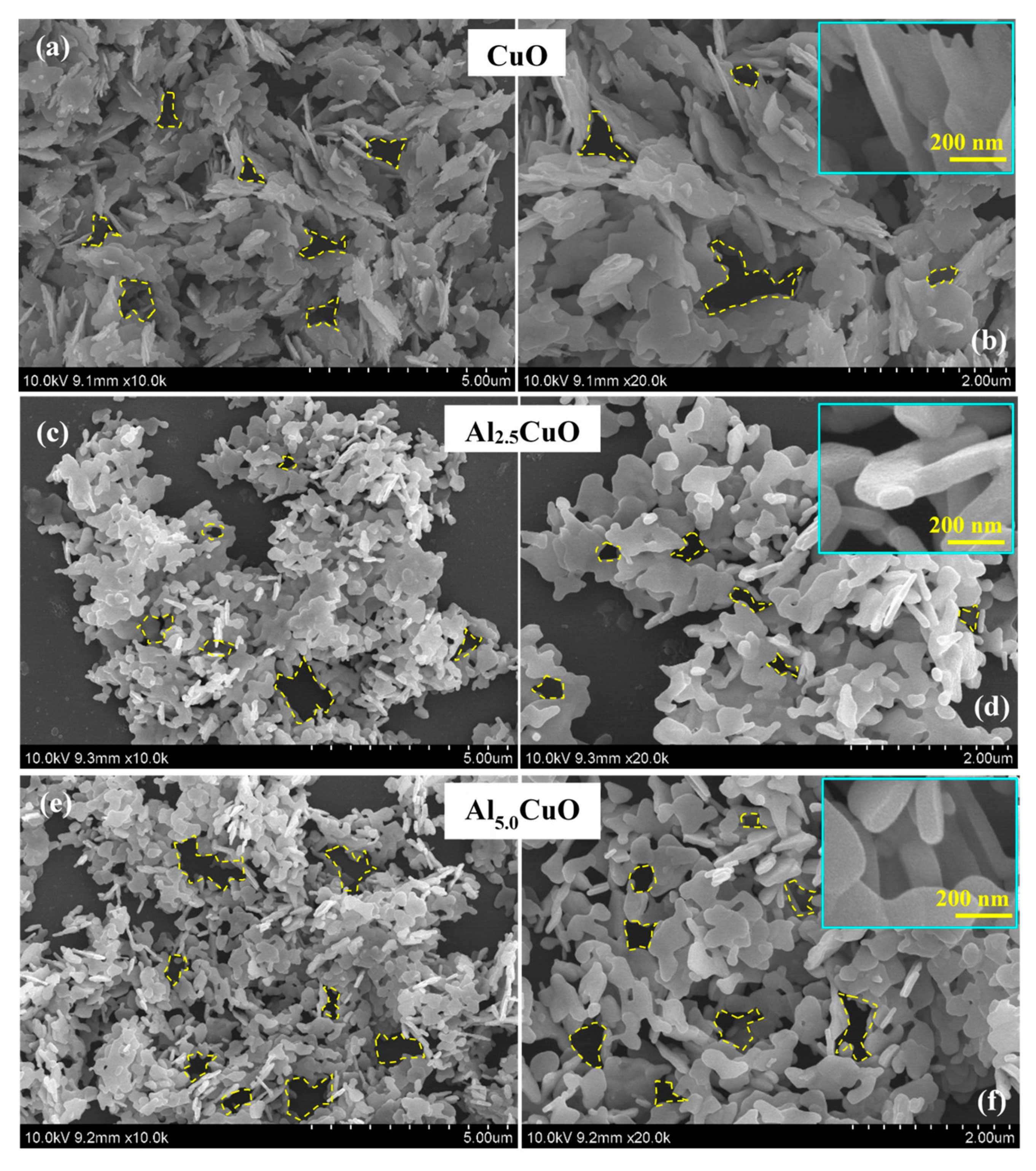
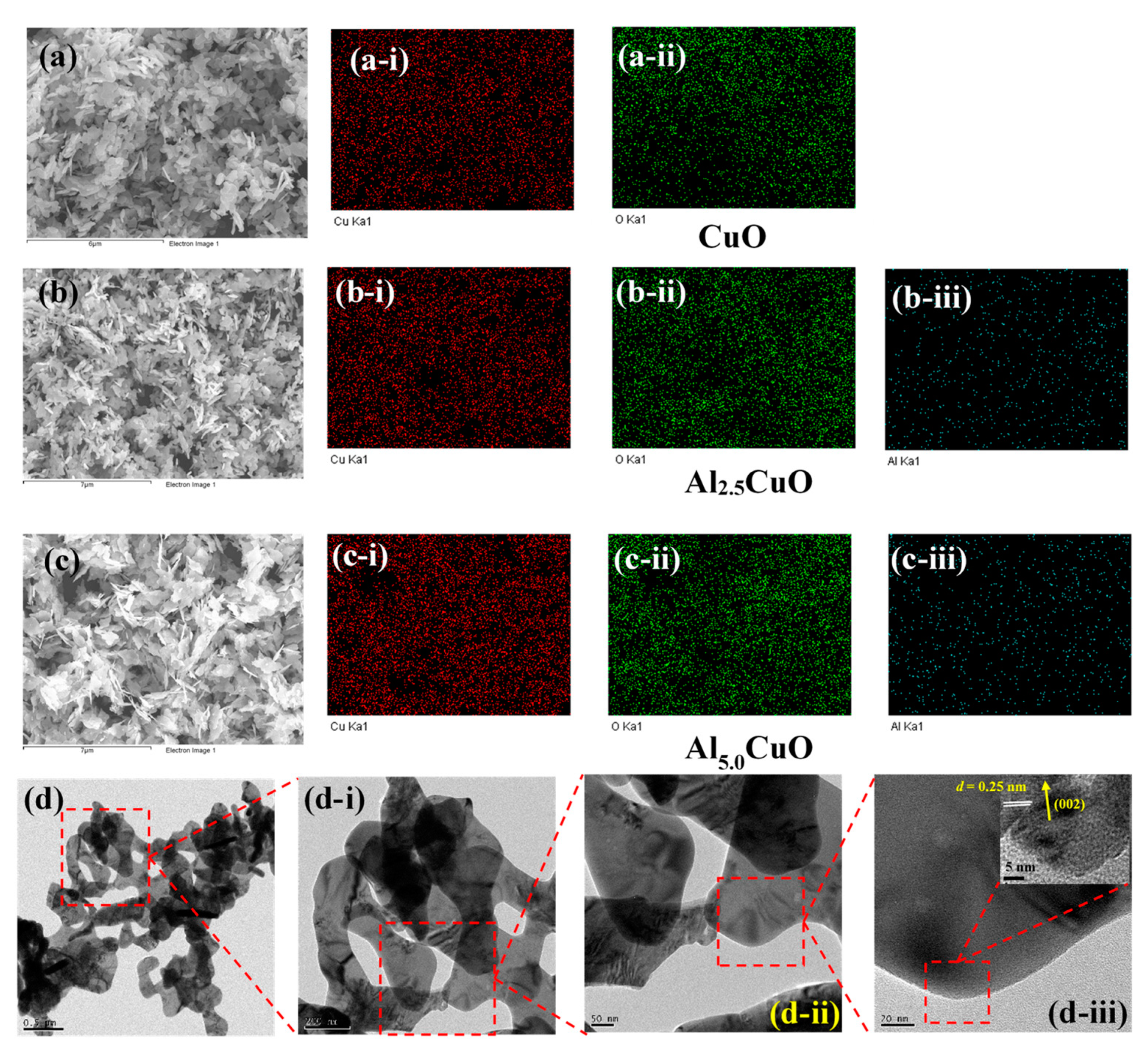
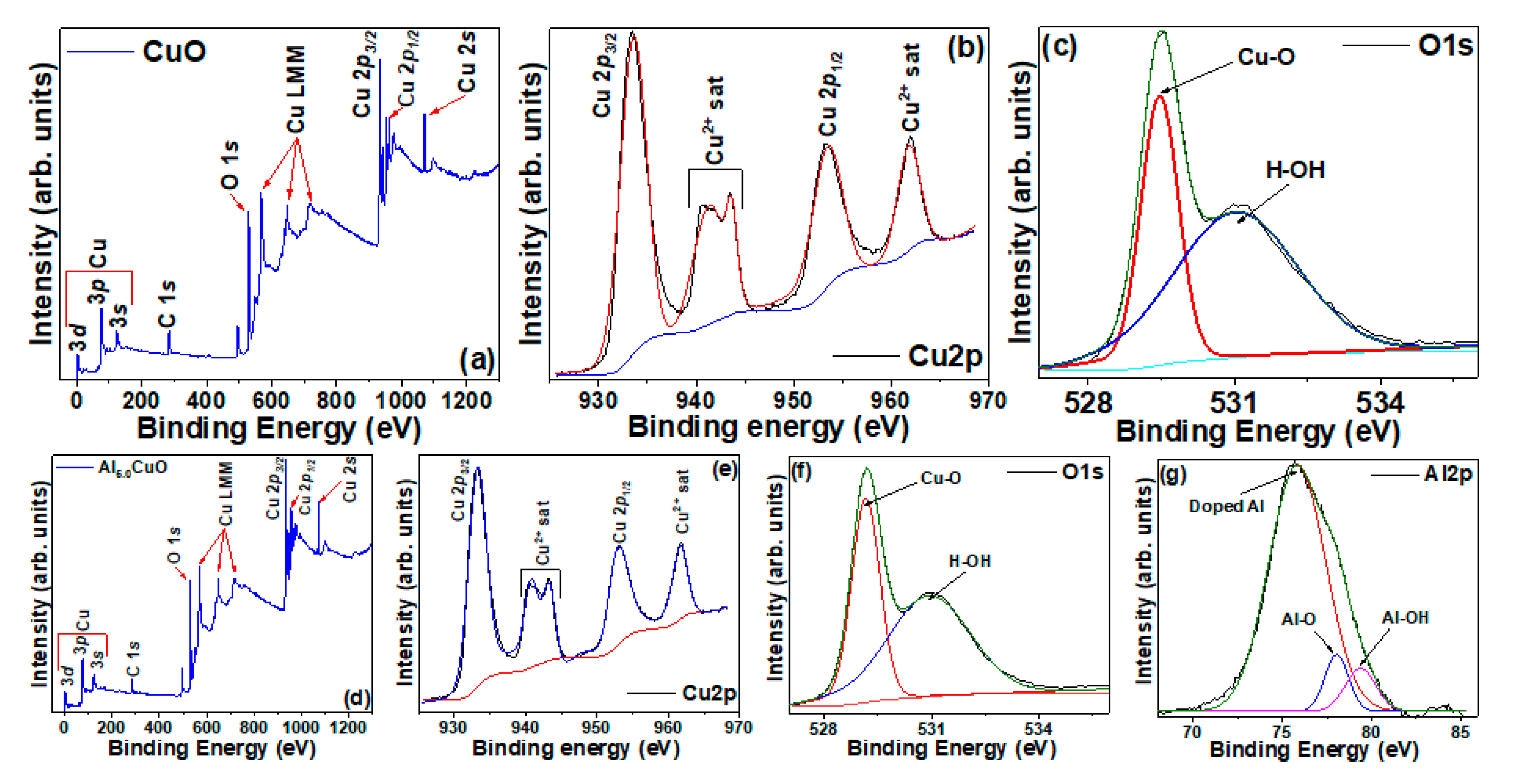
3.1. Physico-Chemical Properties

The structural properties of the samples were investigated using XRD measurements. Figure 1a represents the XRD patterns of the undoped and Al-doped CuO. All the peaks of the undoped sample were indexed as the tenorite copper oxide (CuO) phase, possessing a monoclinic structure with a C2/c space group, with lattice parameters of a = 4.68 Å, b = 3.53 Å, c = 5.13 Å, and β = 99.55°, respectively (JCPDS ICDD file Card # 00-045-0937).
Moreover, no impurity (such as Cu(OH)2,) and/or other phases of copper oxides (such as Cu2O) were detected, indicating the high phase purity of the samples. For doped samples, similar peaks were also observed with no impurity phases (Al2O3, etc.). Regarding the relative peak positions and intensities between the doped and undoped samples, Figure 1b depicts slight high-2θ shifts of the (002) and (111) peaks of the doped samples over the undoped one (similar shifts were also observed for the other peaks). It is well known that in a polycrystalline aggregate, stress is generated within the individual crystallites in a grain due to the restraint by the neighbors, leading to uniform and/or non-uniform strain within the sample. For uniform strain, this is reflected by a shift in the diffraction peaks (high-2θ shift for uniform compressive strain and low-2θ shift for uniform tensile strain). For non-uniform strain, a peak broadening (the so-called “strain-broadening”) is observed without changing the peak position [40]. Thermodynamically, both uniform and non-uniform strains are expected to be present in a nanostructured sample. In the current case, both high-2θ peak shift and peak broadening (higher full-width-at-half-maxima (FWHM), β) of the doped samples over undoped sample were observed (cf. Table 1), indicating that doped samples were slightly strained. The origin of this strain generation stemmed from the difference in the ionic radii of Cu2+ (73 pm) and Al3+ (53 pm). During the doping process, as the Al3+ ions had a lower ionic radius than that of Cu2+, the incorporation of Al atoms into the Cu sites (substitutional doping) was energetically favored, leading to uniform compressive strain generation. Additionally, interstitial doping of Al3+ ions is also thermodynamically possible, which may create non-uniform strain. Moreover, a decrease in the peak intensities of the doped samples over the undoped one (cf. Figure 1b) also indicates that the “particle-broadening effect” may also be present within the samples, which generally leads to an increase in FWHM and decrease in the peak intensity with the decreasing particle size.
To verify this further, the relative peak intensity/position/FWHM of the doped samples (Al2.5CuO and Al5.0CuO) were also investigated, which revealed that the peak positions between these two samples were almost identical, while FWHM was slightly increased (and the peak intensity was slightly decreased) for Al5.0CuO over Al2.5CuO (cf. Figure 1b and Table 1). This indicates that the particle-broadening effect was highly likely to be present within the doped samples. To probe this in detail, size−strain calculations of all the samples were performed according to the following equation [41]:
β   c o s θ λ = 1 L + ε   s i n θ λ
where β is the FWHM of the diffraction peaks (in radian), θ is the diffraction angle (in deg.), λ is the X-ray wavelength used during XRD measurements (= 0.154056 nm), L is the crystallite size (in nm), and ε is the strain. A plot of β   c o s θ λ vs. s i n θ λ would be a straight line, the slope of which would carry the information of the strain and the reciprocal of the intercept would provide the crystallite size of the samples. Figure 1c–e provides the size-strain calculations of the samples, which show that the strain was increased as CuO < Al2.5CuO < Al5.0CuO, whereas the crystallite size was decreased as CuO > Al2.5CuO > Al5.0CuO (cf. Table 1). This proves that both strain-broadening and particle-broadening effects were present within the doped samples. Apparently, Al doping created a small alteration in the crystal symmetry of CuO due to the lesser ionic radius of Al3+ against Cu2+, leading to the formation of defects and vacancies at the lattice sites, which caused charge imbalance. Hence, these strained samples with considerable doping sites provided very high charge storage centers for an excellent electrochemical performance, as described later.
The morphology of the CuO, Al2.5CuO, and Al5.0CuO samples was investigated using FESEM. Figure 2 represents the SEM micrographs of all of the samples at two different magnifications. The formation of some two-dimensional (2D) nanoflake-like structures was observed, with many voids and cavities (some of those are marked on the Figure 2). These would provide very high active surface sites, as well as suitable pathways and shorter diffusion lengths for the ionic transportation, which would be highly favorable for improved electrochemical properties of the samples. A slight decrease in the average dimensions of the nanoflakes was observed with doping. A decrease in the average crystallite size of the samples with doping (as observed in the XRD analysis, cf. Figure 1) manifested a decrease in the average particle size of the nanoflakes. The changes in the d-values of the related (hkl) planes led to this morphological evolution, as corroborated by the XRD data (Figure 1b). For example, the d values for undoped CuO were calculated to be d002 = 0.2530 nm and d111 = 0.2324 nm, respectively (matching the JCPDS ICDD file Card # 00-045-0937). For doped samples, these values were around d002 = 0.2520 nm and d111 = 0.2318 nm. Evidently, the lower ionic radius of Al3+ (53 pm) against Cu2+ (73 pm) led to a decrease in d values of the doped samples. This subsequently decreases the average crystallite size, so also decreases the average dimensions of the doped samples. The insets show the close-up views of the nanoflakes, which depict a nanoflake width of around 50–80 nm. The EDX elemental mapping of the samples was performed through the FESEM instrument, and is represented in Figure 3. The presence of elemental Cu and O (along with Al for doped samples) was clearly visible and were uniformly distributed, indicating the well-dispersed elemental composition of the samples to create nanostructured doped and undoped CuO. The atomic percentages of the samples are given in Table 1, showing near-stoichiometric values with a slight excess of copper for all of the samples. In general, copper oxides showed p-type semiconductivity due to the nonstoichiometric copper vacancy or oxygen excess, which was manifested due to the comparable energy states of Cu 3d levels against O 2p levels, which delocalized the holes [15]. In the current case, due to the hydrothermal condition with a controlled atmosphere, some interstitial Cu defects were most probably created, leading to slight metal excess. These nonstoichiometric Cu interstitials within the nanoflakes electrodes provided the Cu(I)/Cu(II) transitions with the electrolyte for excess redox reactions during electrochemical performance in order to promote the unusual battery-type behavior, as discussed later. Regarding doped samples, the presence of elemental Al was observed with 1.8 at% for Al2.5CuO and 3.3 at% for Al5.0CuO, respectively. Evidently, with the increasing wt% of the dopant source in the precursor solutions, the at% of Al in the final products also increased accordingly. To show that the doping was uniformly distributed over the entire sample, first, we chose a relatively larger area of interest for elemental mapping over a 12 μm × 12 μm area (as shown in Figure 3a–c), which depicts the uniform distribution of Al atoms (cf. Figure 3b(iii),c(iii)). Second, we obtained the elemental composition from five such areas over different regions of the samples, and took the average. The variation was only ± 0.1 at% over these regions, indicating that the doping concentration was highly uniform over the entire samples.
The TEM micrographs of the Al5.0CuO samples are presented in Figure 3d–d(iii) at different magnifications. The regions of interest were highlighted within each image. Keeping parity with the FESEM images, a 2D nanoflake structure with a porous morphology, with voids and cavities, was clearly visible. These voids and cavities are highly favorable for electrolyte ions to diffuse into the inner microstructure of the electrodes to access the internal redox-active sites so as to promote the unusual battery-type behavior, as discussed later. The inset of Figure 3d(iii) represents the HRTEM image of the nanoflake, showing a highly crystalline structure with proper lattice spacing of d = 0.25 nm for (002) planes of monoclinic CuO, thus matching with the XRD data (cf. Figure 1a). It should be noted that for the other two samples (CuO and Al2.5CuO), almost identical microstructures were obtained (with slightly varied dimensions of the nanoflakes); hence, they were not presented.
XPS measurements were performed to identify the surface oxidation states and chemical bonding of the samples. The XPS survey spectra of CuO and Al5.0CuO are presented in Figure 4a,d, respectively. The presence of O, Cu, and C (along with some auger lines) was identified. The presence of C-related peaks may originate from atmospheric CO2, adsorbed on the surface of the samples during sample preparation and handling, as well as from adventitious hydrocarbons from the XPS instrument itself. Because of a relatively small atomic percentage of Al, no Al peaks were resolved in the survey spectrum of the Al5.0CuO sample, although corresponding high-resolution spectra were obtained properly (cf. Figure 4g). The core-level high-resolution Cu 2p spectra of CuO and Al5.0CuO samples (cf. Figure 4b,e) were deconvoluted into several sub-peaks. The peaks at 933.6 eV (for CuO) and 933.3 eV (for Al5.0CuO) corresponded to the Cu 2p3/2 state, whereas the peaks at 953.7 eV (for CuO) and 953.2 eV (for Al5.0CuO) related to Cu 2p1/2 state, with a spin-energy separation of 20 eV (in agreement with the standard spectrum of CuO), indicating the presence of the Cu2+ state in undoped and doped CuO. Additionally, the shake-up satellite peaks of Cu 2p3/2 and Cu 2p1/2 were also observed at an average of ~9 eV higher binding energy sides for the main peaks in both the samples, which were due to unfilled Cu 3d9 configuration in the ground states, further verifying the existence of CuO at the surface. This is because the 3d shell in Cu2O was expected to be completely filled, thus nullifying its presence in the as-synthesized samples. The high-resolution O 1s spectra of CuO and Al5.0CuO are presented in Figure 4c,f, respectively, both of which were deconvoluted into two sub-peaks that corresponded to the oxygen ions (O2−) in CuO (Cu-O) and the surface absorbed oxygen from the -OH group and water (H-OH). The broad integrated area of the H-OH peaks in both the samples indicated abundant physiosorbed oxygen on the surface of the nanoflakes to provide defect sites, which possessed a strong electrostatic affinity to OH ions in basic media, thus markedly accelerating the electrochemical activities [18,21,34,42]. The high-resolution Al 2p spectrum of the Al5.0CuO sample (cf. Figure 4g) showed three deconvoluted peaks at 75.7 eV (corresponding to Al(0) state, representing Al doped into CuO phase), 78.1 eV (representing Al-O bonding for Al3+ states in Al2O3, originating from surface oxidation), and 79.4 eV (representing Al-OH states due to intercalation of the surface hydroxyl ions). The higher integral area of the Al(0) state against the Al-O and Al-OH states clearly indicated the successful doping of Al atoms into the CuO lattice [38,43,44]. It should be noted here that the XPS spectra of Al2.5CuO was almost identical to that of Al5.0CuO, and hence were not presented here.

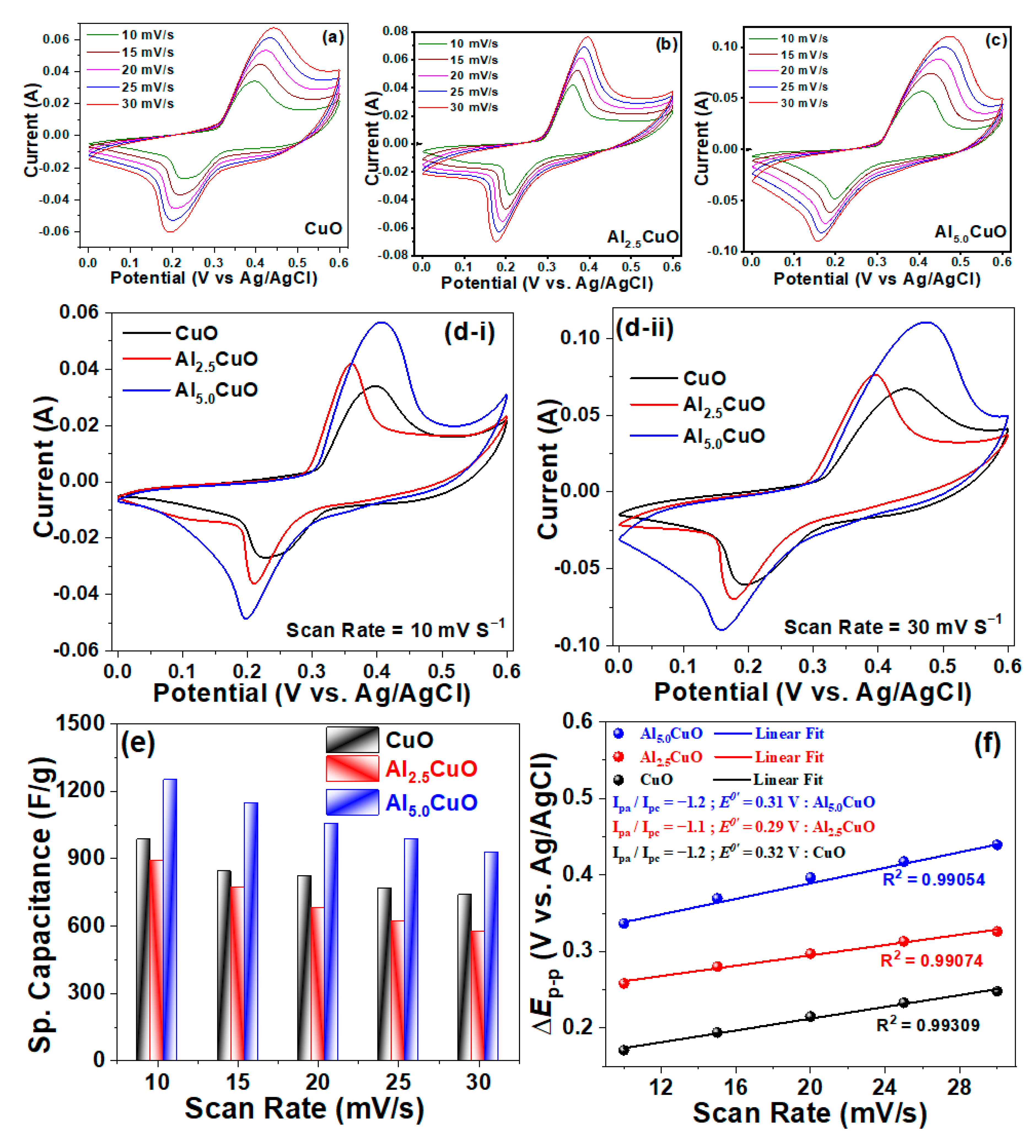
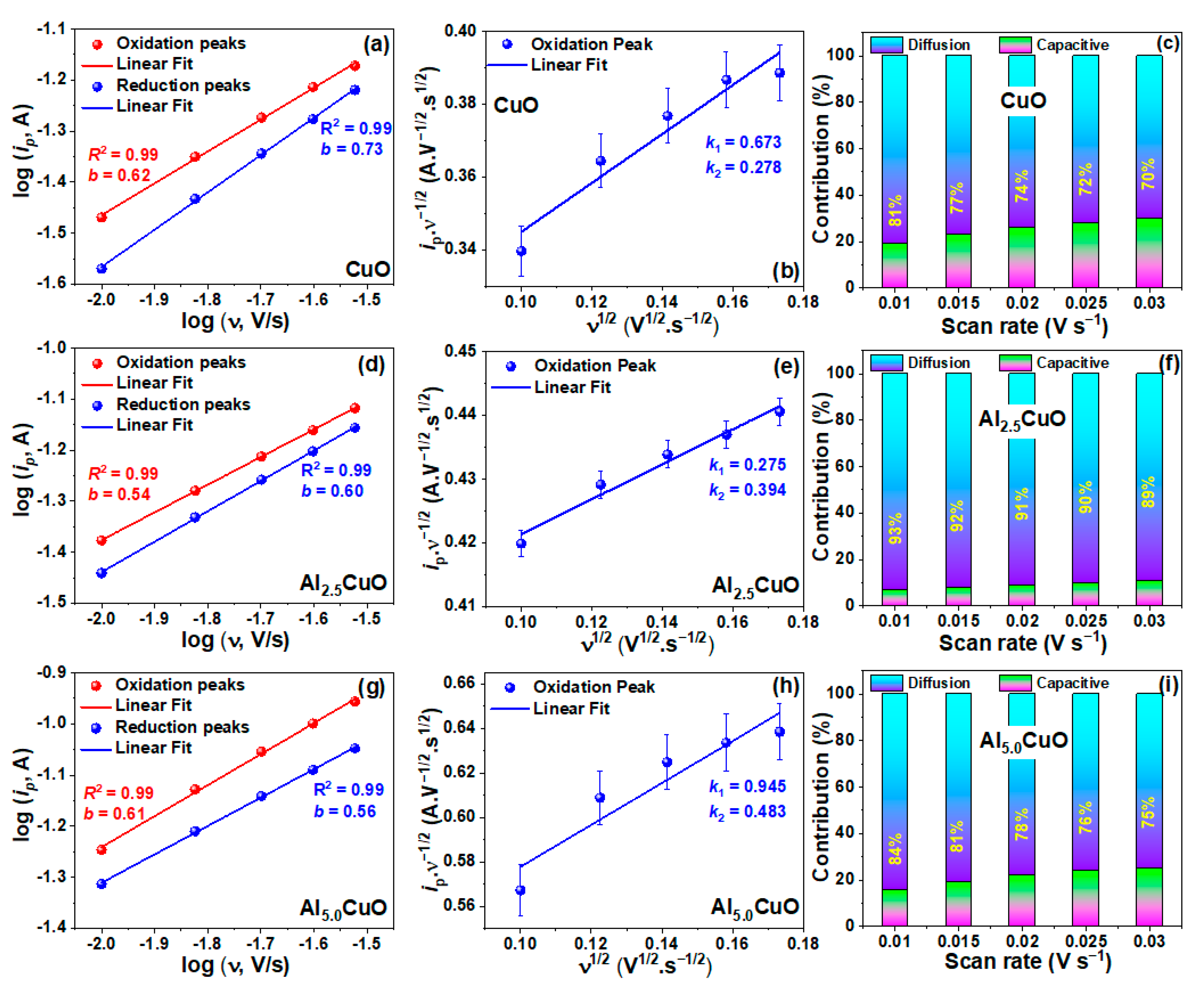
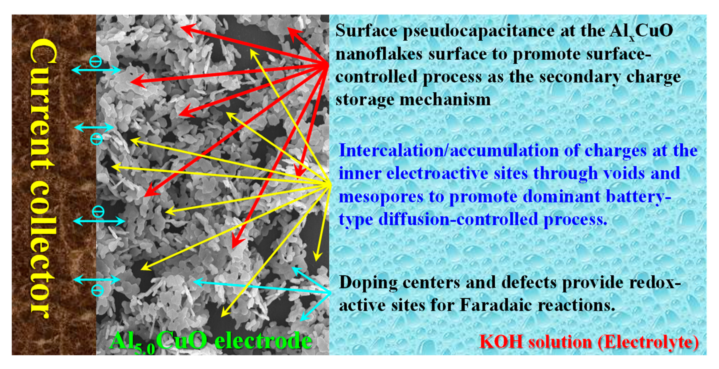
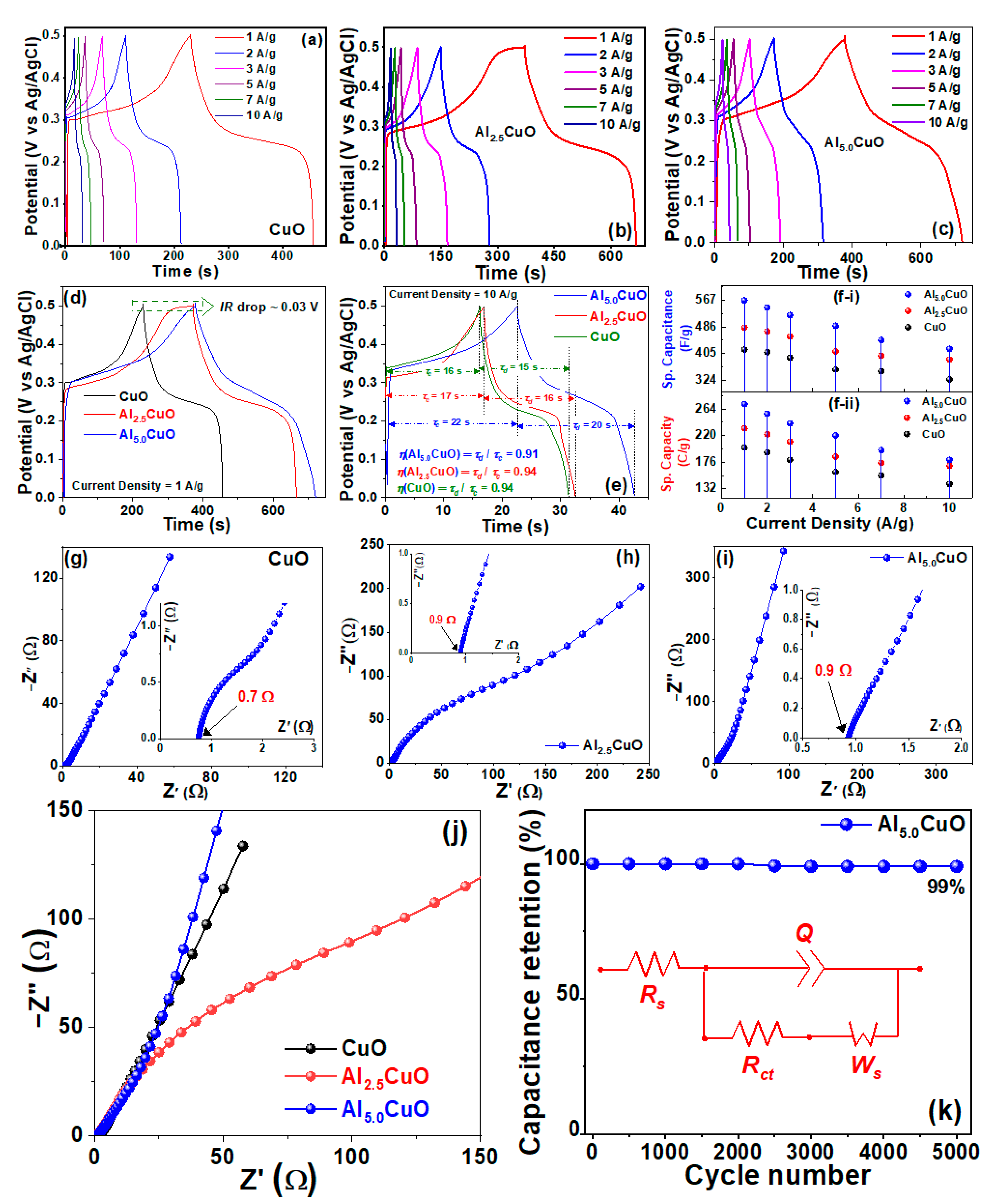
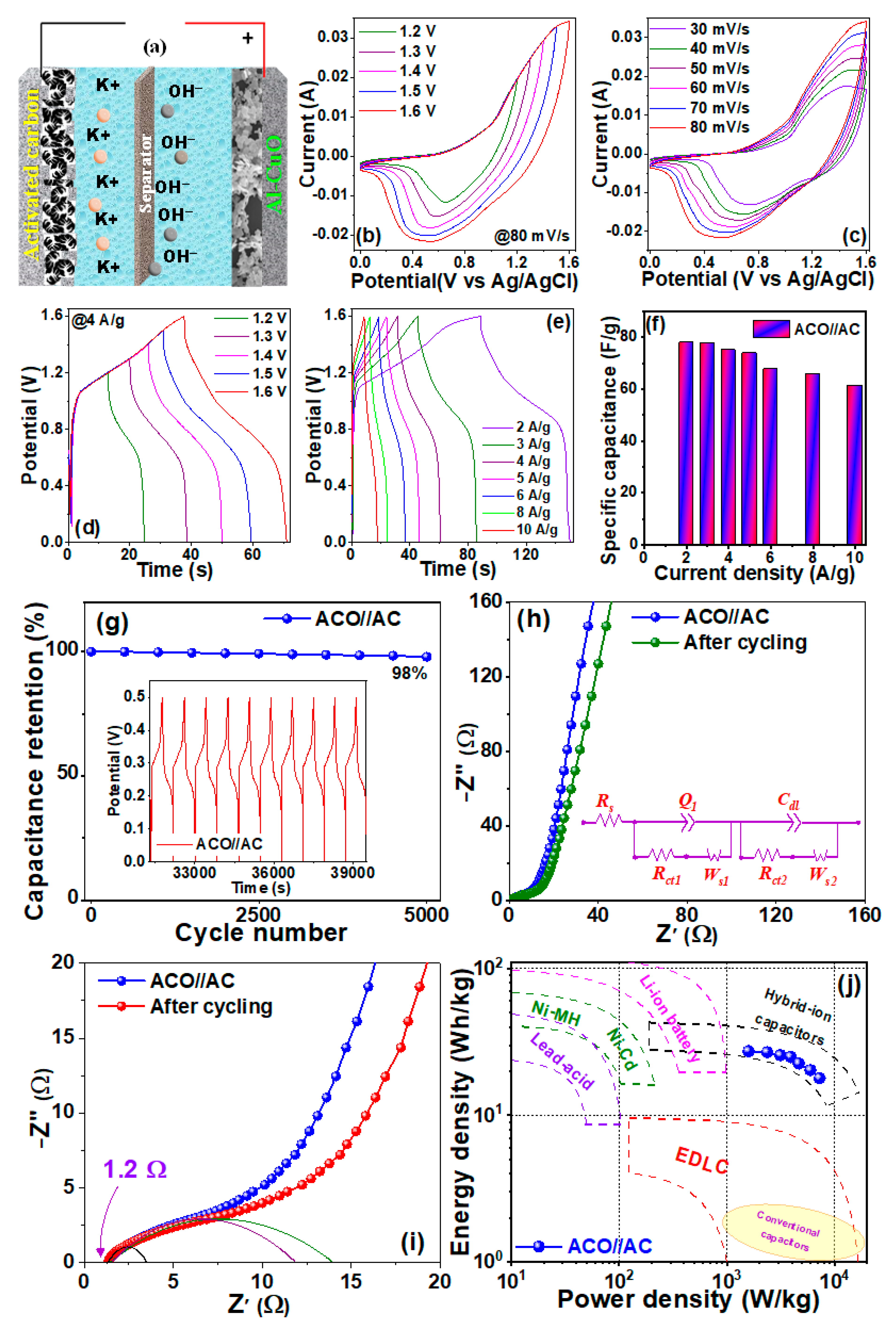
3.2. Electrochemical Properties

The supercapacitive performance of the undoped and Al-doped samples was examined via CV measurements in a three-electrode system (half-cell). Figure 5a–c shows the CV curves of CuO, Al2.5CuO, and Al5.0CuO electrodes, respectively, at different scan rates. Strong pairs of anodic and cathodic peaks were observed in an aqueous alkaline medium (KOH) within 0.0 to 0.6 V (vs. Ag/AgCl), which can be attributed to the quasi-reversible electron transfer for Cu(I)/Cu(II) transitions, as proposed by the following complex Faradaic redox reactions [12,45]:
2 C u O + H 2 O + 2 e C u 2 O + 2 O H
2 C u ( O H ) 2 + 2 e C u 2 O + H 2 O + 2 O H
C u O + H 2 O + e C u O H + O H
C u ( O H ) 2 + e C u O H + O H
Apparently, the oxidation−reduction events occurred through the charge transfer process, and during charging, the active material of the electrode (undoped and doped CuO) underwent a reduction (from CuO/Cu(OH)2 to Cu2O/CuOH), resulting in the cathodic peak around 0.15–0.25 V (for all the three electrodes). Likewise, during discharging, the electrode material underwent an oxidation (from Cu2O/CuOH to CuO/Cu(OH)2) to give rise to the anodic peak around 0.35–0.5 V. Although the Faradaic redox reactions, shown in Equation (8), indicate the pseudocapacitive charge storage mechanism of the electrodes, with increasing scan rates, the CV current also increased along with a shift in the anodic peaks towards the higher potentials and the cathodic peaks towards the lower potentials. This indicates the quasi-reversible nature of the redox reaction and the electrochemical mechanism is interfacial diffusion-controlled (battery-type) with a good conductivity and facile ion transport kinetics [14]. However, the lack of change in the shape of the CV curves for all electrodes when increasing the scan rate suggests improved mass transport and very high rate-capability due to favorable electronic/ionic conduction, manifested by the nanostructured surface with good crystallinity of the electrodes that provide a high specific surface area and short diffusion paths for both electrons and ions, resulting in very good electrochemical behavior. Figure 5d(i),d(ii) compares the CV curves of all the three electrodes at lower (10 mV/s) and higher (30 mV/s) scan rates, respectively. The Al5.0CuO electrode showed a larger integral area for the CV curve than the others because of higher electroactive sites due to the increased Al doping. Likewise, Al2.5CuO also showed higher peak currents than that of the CuO electrode, while the redox peaks became sharper than the other electrodes. This indicates that the diffusion-controlled process (battery-type) was more dominant in the Al2.5CuO electrode than that of the Al5.0CuO electrode, probably due to the energetically favorable doping concentration in the former sample that synergistically provided optimum diffusion paths for the ions in order to access inner electroactive doping sites. For the latter sample, excess Al doping probably created more surface-active sites to promote the surface-controlled process (capacitive-type via surface pseudocapacitance), thus broadening the redox peaks.
To further elucidate the electrochemical kinetics, the gravimetric capacitances of the electrodes were calculated from the CV curves using the following equation [46]:
C s = 1 2 m ν V 1 V 2 I V d V
where ν (V/s) is the scan rate, V2V1 (V) is the potential window, I (A) is the current, and m (g) is the mass loading. The estimated capacitance values were observed to be decreased with the increased scan rates for all of the electrodes (cf. Figure 5e). For example, in the Al5.0CuO electrode, the Cs value of 1250.0 F/g (@10 mV/s) decreased to 927.3 F/g (@30 mV/s). Likewise, for Al2.5CuO, the value of 890.5 F/g (@10 mV/s) decreased to 576.2 F/g (@30 mV/s). Similarly, for the CuO electrode, the capacitance decreased from 984.2 F/g (@10 mV/s) to 736.8 F/g (@30 mV/s). Generally, in most cases, the specific capacitance decreased with the increased scan rate due to diffusion limitations at higher scan rates [46], which would be more pronounced in a quasi-reversible process [47,48] where the peak-to-peak separation potential (ΔEp-p = EpaEpc) between the cathodic and anodic peaks would vary linearly with scan rates, and the peak anodic current-to-peak cathodic current ratio (Ipa/Ipc) and the formal potential E0′ would remain near constant. Practically, in most of the electrochemical processes, the so-called reversible process was thermodynamically mostly quasi-reversible. In our case, for all the electrodes, we also observed a linear variation of ΔEp-p with a scan rate (cf. Figure 5f), along with near-constant values for Ipa/Ipc (~−1.1 to −1.2) and E0′ (~0.29–0.32 V), indicating a typical quasi-reversible process due to the statistical presence of various defect centers, which would trap charges during cathodic and anodic sweeps [46]. Precisely, in an intrinsic CuO, synthesized under hydrothermal conditions (as in the current case), different types of defects can exist, such as copper vacancy ( V C u ), oxygen interstitial ( O i ), and oxygen vacancy ( V O ). For Al-doped CuO, additional defects in Al atoms into the Cu sites ( A l C u ), Al interstitials ( A l i ), etc., could also be present (denoted according to Kröger−Vink notations), all of which could promote charge storage/transfer properties of the electrodes [49].
To further analyze the charge storage mechanism of the electrodes, the power law was applied to the CV data as follows [50]:
i p ν = a ν b
where ip (A) is the peak current, ν (V/s) is the scan rate, and a and b are variable parameters (b normally ranges from 0.5 to 1, b = 0.5 denotes the dominant diffusion-controlled process while b = 1 denotes dominant surface-controlled mechanism, and a b-value between 0.5 and 1 suggests a combination of diffusion and capacitive control processes [34]). Figure 6a,d,g represents the log(ip) vs. log(ν) for CuO, Al2.5CuO, and Al5.0CuO electrodes, respectively, which showed a linear variation with b-values (for reduction/oxidation peaks) around 0.73/0.62 (for CuO), 0.60/0.54 (for Al2.5CuO), and 0.56/0.61 (for Al5.0CuO), respectively, indicating that both surface-controlled (capacitive-type) and diffusion-controlled (battery-type) processes were present in the charge storage mechanism. Additionally, the relative contributions of the above two processes on the overall charge storage performance are examined via Cottrell’s equation [51]:
i p ν = k 1 ν + k 2 ν 1 / 2
which is further rearranged as follows [50]:
i p ν 1 / 2 = k 1 ν 1 / 2 + k 2
where k1ν corresponds to the surface-controlled (capacitive-type) and k2ν1/2 represents diffusion-controlled (battery-type) charge storage mechanism, with k1 and k2 obtained from the slope and intercept of the linear fit of Equation (10c), respectively. Figure 6b,e,h represents the ip /ν1/2 vs. ν1/2 plots for CuO, Al2.5CuO, and Al5.0CuO electrodes, respectively, which showed a linear variation with k1/k2 values around 0.0.673/0.278 (for CuO), 0.0.275/0.394 (for Al2.5CuO), and 0.945/0.483 (for Al5.0CuO), respectively. The corresponding relative contributions of the battery-type (diffusion-controlled) and capacitive-type (surface-controlled) behaviors at different scan rates for all three electrodes are presented in Figure 6c,f,i. Evidently, the battery-type behavior was observed to be the dominant mechanism for all of the electrodes, with Al2.5CuO having the highest contribution for the diffusion-controlled process (89%–93%), thus maintaining parity with the corresponding CV curves.
As stated earlier, the optimum doping concentration, along with relatively bigger voids within the nanoflakes, facilitate the accumulation/intercalation of charges at the inner electroactive sites to contribute towards battery-type diffusion capacitance. For the first time, a dominant battery-type electrochemical behavior was observed in the CuO nanostructures (either doped or undoped). Previously, only one report exhibited the battery-type behavior of binary ZnO, grown within graphene foam, which was correlated with the large structural defects within the electrodes [9]. In our case as well, as stated earlier, various defect states were present within the electrodes (both at the surface and interior regions) due to doping, manifesting strong redox-active sites. In addition, because of the unique nanostructured morphology with a large number of pores, voids, and cavities with smaller diffusion paths, the accumulation/intercalation of charges at the inner electroactive sites facilitated the diffusion-controlled (battery-type) process. Regarding the best supercapacitive performance for the Al5.0CuO electrode (against other electrodes), in addition to the above reasons, excess Al doping probably created more surface-active sites to promote surface-controlled processes (capacitive-type via surface pseudocapacitance), thus providing a combinatorial effect to enhance the overall electrochemical properties. Therefore, as depicted in Scheme 2, the novel combinatorial charge-storage mechanism was manifested because of the following: (i) intercalation and/or accumulation of charges at the inner electroactive sites of the materials through voids and mesopores to promote the dominant battery-type diffusion-controlled process, (ii) the low-dimensional nanostructure (2D nanoflakes morphology) provides abundant active surface sites to promote a capacitive-type surface-controlled process via surface pseudocapacitance, and (iii) the doping of Al (substitutional as well as interstitial) creates large numbers of doping centers and defects to provide enormous redox-active sites to promote Faradaic reactions. Moreover, the capacitive contribution (mainly pseudocapacitive surface process) was observed to increase with the scan rate, which was due to the inability of the electrolyte ions to access the inner surfaces of the electrodes at faster kinetics.
The GCD measurements of all three electrodes at different current densities are presented in Figure 7a–c at a potential window of 0–0.5 V (vs. Ag/AgCl), which was less than that used for the CV measurements (0–0.6 V). The probable occurrence of oxygen evolution reaction at the higher current densities could affect the actual GCD results, as a result of which a smaller potential window (against CV measurements) was chosen for the GCD measurements so that it could reach the boundary at a lower current density. Similar observations were reported in several other publications too [50,52,53,54]. The near symmetric charge−discharge profiles along with voltage plateaus at different current densities were in agreement with the CV curves, suggesting excellent rate characteristics with both pseudocapacitive and battery-type behaviors. Figure 7d,e compares the GCD curves of the three electrodes at lower (1 A/g) and higher (10 A/g) current densities, respectively. The 1 A/g GCD profiles revealed higher non-linearity at the peak of the charging curves against the 10 A/g GCD profiles, which was due to the higher surface pseudocapacitance of the electrodes at a lower current density, while the diffusion of ions at the inner regions were activated at higher current densities, leading to quasi-triangular shapes of the curves near the charging−discharging peaks @10 A/g profiles. In addition, the coulombic efficiencies ( η = τ d τ c ; where τd/τc = discharging/charging times) of the electrodes were found to be very high (~91%–94%, cf. Figure 7e), indicating an excellent reversibility. In particular, the Al5.0CuO electrode showed a higher discharge profile, indicating better electrochemical performance over other electrodes due to the presence of both surface-controlled (surface pseudocapacitance) and diffusion-controlled (battery-type) processes, as described in Scheme 2. In addition, the IR drop for all of the electrodes was observed to be as low as 0.03 V (cf. Figure 7d), indicating very low interfacial resistances at the electrolyte/active-material and active-material/current collector interfaces [8,10,12,13].
The specific capacitance (in F/g) and specific capacity (in C/g), due to the combinatorial effects of the surface pseudocapacitance and battery-type behavior of the electrodes, were calculated as a function of current density and the results are presented in Figure 7f(i),f(ii), respectively. A very high specific capacitance (capacity) of 567 F/g (272 C/g) was observed for the Al5.0CuO electrode at a 1 A/g current density. These values were significantly higher than the values reported for similar electrodes with comparable current densities, as shown in Table 2. In addition, a progressive increase in the specific capacity/capacitance value was observed with the increased Al-doping concentrations. For example, at a 1 A/g current density, these values increased from 200 C g−1/417 Fg−1 (for CuO), 232 C g−1/483 Fg−1 (for Al2.5CuO), and 272 C g−1/567 Fg−1 (for Al5.0CuO). Evidently, higher Al-doping provided increased defects and doping sites to enhance the redox activity so as to improve the supercapacitive performance. Additionally, a decrease in the specific capacitance (capacity) value at a high current density was observed, which was due to the fast charging−discharging rate that prevented electrolyte ions from penetrating the interior of the material while at lower current densities; maximum utilization of the active material was facilitated due to the greater penetration time for electrolyte ions into the interior of the material to provide a high specific capacitance/capacity [14,17,45].
To understand the electrochemical kinetics in more detail, EIS characterizations were performed and the corresponding Nyquist plots for all of the electrodes are presented in Figure 7g–i, respectively. The solution contact resistances (also called equivalent series resistance (RΩ)), shown at the high-frequency intercepts to the real impedance axes of the corresponding inset figures, were found to be very low (~0.7–0.9 Ω), indicating that the electrolyte resistance and the contact resistances at the interface between the electrodes and electrolyte were very low. The depressed semi-circles at the high-frequency region of CuO and Al2.5CuO (inset of Figure 7g,h) revealed the presence of some charge-transfer resistance (Rct) between the electrode and electrolyte; however, for the Al5.0CuO electrode, this semi-circular region was found to be almost non-existent (a near-vertical nature of the curve at the high frequency region was observed, cf. inset of Figure 7i), indicating negligible charge-transfer resistance (Rct), manifested by the presence of large number of defect centers due to excess doping so as to provide higher electroactive sites against other electrodes. Moreover, in the low frequency region, all the electrodes showed a linear variation of curves with a slope around 45°–75° against the real impedance axes (cf. Figure 7j), indicating that the electrochemical kinetics were a combination of both surface-controlled and diffusion-controlled processes, with the latter being dominant, which is in agreement with the CV data, where 75%–95% contributions from the battery-type diffusion-controlled charge storage mechanism were observed. In particular, for the Al2.5CuO electrode, the slope was observed to be around 45O, indicating dominant battery-type behavior for this electrode, maintaining parity with the CV data, where almost an 93% diffusion-controlled mechanism was observed (cf. Figure 6f). Finally, based on the performance of the three electrodes, Al5.0CuO was found to be the best performing electrode with the highest specific capacity/capacitance against other electrodes, and, hence, the cyclic stability of this electrode was tested over 5000 cycles (@ 1 A/g current density) and is presented in Figure 7k. Clearly, almost 99% capacity retention was observed over the entire cycles, indicating an excellent rate capability [8,12,13,17,45]. This highly efficient cycling stability of the electrodes over large cycles is attributed to the unique 2D nanostructure with porous morphology of the active material with a large number of cavities and voids, which (a) provides numerous electrochemically active sites and a shorter diffusion pathway for rapid electrolyte ion transfer; (b) manifests a higher surface-to-volume ratio for the charge to distribute, thus enhancing the electrochemical performance; and (c) prevents the structural degradation caused by the volume expansion of the reactive material during the discharge/charge process. Additionally, the efficient and sustained electrochemical activities of the Al-doped CuO can be correlated with the highly tolerant Cu2+ ions in the CuO system towards Al-doping, which (a) provide partially filled 3d orbitals in Cu2+ ions, as well as Al3+ dopant sites, to facilitate more efficient engagement in redox processes against pristine CuO, and (b) manifest large number of defect centers due to excess doping to provide higher electroactive sites against other undoped electrodes to provide negligible charge-transfer resistance, Rct (as observed by the near-vertical nature of the Nyquist plot of Al5.0CuO at high frequency region, cf. inset of Figure 7i). Therefore, from the electrochemical characterizations under the three-electrode system, it becomes evident that the Al5.0CuO electrode had the best supercapacitive performance, not only against the other two electrodes, but with respect to the literature values of similar electrodes; the electrochemical properties were significantly higher (cf. Table 2) and, hence, should be considered as the ideal candidate for a hybrid supercapacitor device (two-electrode system) due to the battery−capacitor charge storage mechanism with a high capacitance/capacity, excellent rate capability, and superior stability.
Regarding the practical charge storage applications, the best performing supercapacitor cell (two-electrode device) was fabricated with Al5.0CuO (ACO) as the positive electrode and activated carbon (AC) as the negative electrode (ACO//AC), and the schematic structure is shown in Figure 8a. To determine the optimum operating voltage of the device, CV measurements of the device were performed at different working voltages ranging from 1.2 V to 1.6 V (cf. Figure 8b), and no distortion of the curves was observed, indicating the absence of hydrogen and oxygen evolution reactions at the positive and negative electrodes, respectively, thus verifying that the maximum working voltage window could be extended up to 1.6 V. Therefore, CV characterizations of the device were performed at different scan rates over a 1.6 V working voltage window, and presented in Figure 8c. The near-rectangular shapes of the CV curves, with identical shapes at different scan rates, indicated the combinatorial effects of the Faradaic redox behavior (from ACO electrode) and double-layer capacitance (from AC electrode) with an excellent rate capability and reversibility. Similarly, the GCD measurements of the device were also performed over various working voltages and, maintaining parity with the CV results, undistorted curves were also obtained up to an optimum voltage window of 1.6 V (cf. Figure 8d). Hence, the GCD analysis of the device was obtained at various current densities at a working voltage difference of 1.6 V (cf. Figure 8e). The non-linear, quasi-symmetric shapes of the curves with relatively longer charging−discharging times depicted a very high charge storage capacity and excellent reversibility. In addition, the specific capacitance, calculated from the GCD data, is presented as a function of current density in Figure 8f, which depicts a maximum value around 80 F/g (@2 A/g), and slightly decreased to 62 F/g (@10 A/g), indicating a very good rate capability. The cycling stability and capacitance retention of the device was observed to be very high as it retained 98% capacitance after 5000 GCD cycles (cf. Figure 8g), and the last 10 GCD cycles (shown in the inset of Figure 8g) revealed highly symmetrical GCD curves without any distortion, indicating excellent stability of the device.
The EIS analysis of the device, in terms of the Nyquist plot, is presented in Figure 8h for the 1st and 5000th cycles, revealing almost similar equivalent series resistance (RΩ ~ 1.2 Ω, cf. Figure 8i), further corroborating the excellent cycling stability of the device. Additionally, as shown in Figure 8i, the high-frequency intercepts at the real axis for both the plots depict two depressed semi-circles, which originated from the charge transfer processes at the positive and negative electrodes, respectively, and the corresponding equivalent circuit is presented at the inset of Figure 8h. The charge transfer resistance (Rct1) between the electrolyte and the positive electrode (ACO) was almost identical (~3.5 Ω, obtained from the diameter of the smaller semi-circle) for both the fresh electrode (1st cycle) and the used electrode (after 5000th cycle), thus confirming the extraordinary stability of the active material and endorsing its excellent charge-transport properties to benefit the superior performance of the hybrid supercapacitor. On the other hand, the bigger semi-circles represent the charge transfer resistance (Rct2) between the electrolyte and the negative electrode (AC), which show a slight increment from 12 Ω (for the 1st cycle, represented by the light blue semi-circle) to 14 Ω (after the 5000th cycle, represented by the light green semi-circle), manifested by the charge accumulation at the AC electrode−electrolyte interface after long cycling to reduce the electroactive sites [12,14,18,26,56,60].
The energy-power performance of the hybrid supercapacitor device is represented by the Ragone plot in Figure 8j, which shows a maximum energy density of 30 Wh/kg at a power density of 1.6 kW/kg, while at a maximum power density of 7.25 kW/kg, an energy density of ~20 Wh/kg was still retained, indicating ~350% power gain over a mere 30% energy expense. All of these values were better than that of the similar symmetric and asymmetric devices reported in the literature (cf. Table 3). In addition, energy-power fields of the Li-ion, Ni-MH, Ni-Cd, and Pb-acid batteries along with EDLC, conventional capacitors, and hybrid-ion capacitors, are superimposed in the above-mentioned Ragone plot (cf. Figure 8j) for comparison. As shown, the energy-power performance of the current device was superior to the EDLCs and conventional capacitors. In addition, the energy densities of the current hybrid device were close to the lower end of the Li-ion batteries, but comparable to the other commercial batteries (such as Ni-MH, Ni-Cd, and lead-acid). In terms of power density, the current device was better than most of the commercial batteries stated above, and it fell within the range of hybrid-ion capacitors such as Li-ion, Na-ion, and K-ion capacitors. Therefore, the current device could be a viable option to fabricate hybrid supercapacitors to overcome the limitations of metal-ion batteries (in terms of power) and supercapacitors (in terms of energy) for next-generation high-performance charge storage devices [3,5,6,61,62,63,64]. Finally, as far as the practical applicability of the supercapacitive device is concerned, two solid-state pouch cells were connected in series with a working voltage of 3.5 V, to light up a 3 mm high-density orange LED (3.2 V, 18 mA), and a blue LED (3.1 V, 18 mA) over time, as shown in Figure 9a–d, thus demonstrating its promising energy storage capability.
As far as the commercial aspects of our device are concerned, although the lithium-ion battery (LIB) is still the most proven technology for energy storage systems, the continuous expectation of cost reduction in large-scale applications (especially in electric vehicles and grids) and growing concerns over the availability of the natural resources for Li-ions have forced researches to look “beyond the Li-ion: technologies [65]. In this respect, alkali-ion/Ni-MH/Ni-Cd/Pb-acid batteries, hybrid-ion capacitors, etc., are becoming potential cost-effective alternatives in applications where energy density is less important (such as load levelling in power grids). For example, the current cost of an LIB module is less than USD 150.00/kWh, whereas the above alternative devices have shown a cost-reduction of more than 50% against LIB technology [65]. In our case, because of the use of low-cost and high abundance raw materials with simple and cost-effective fabrication techniques, we believe that the cost can further be reduced and, hence, can become an excellent alternative to the existing energy storage systems. Therefore, in our opinion, the current material, device, and technology have great potential for commercialization in diverse device applications.

4. Conclusions

Undoped and Al-doped CuO nanoflakes were fabricated via a simple co-precipitation method. The physico-chemical and electrochemical properties of the materials were investigated as a function of the doping concentration. Here, 5 wt% Al doping revealed the optimum electrochemical performance for the Al-CuO electrode, due to its high porosity and large defects and doping sites in order to enhance the redox activity to improve the supercapacitive performance. A dominant battery-type charge-storage mechanism was observed due to the accumulation/intercalation of charges at the inner electroactive sites of the nanoflakes through the large number of voids and cavities to promote the diffusion-controlled process. Additionally, surface pseudocapacitance was also observed to be present as the secondary electrochemical mechanism due to the optimal Al doping, which created considerable redox active sites to promote the surface-controlled capacitive process. This battery−capacitor combinatorial effect enhanced the specific capacity of the electrode considerably, and a hybrid supercapacitor device, made up of best performing Al-CuO as the positrode and AC as the negatrode, was fabricated that demonstrated a remarkable energy-power performance, excellent cycle life, and high capacitance, which were comparable to some of the state-of-the-art commercial devices. We envision that the process and material, with novel hybrid battery−capacitor properties, can have a wide range of applications in supercapacitors, hybrid-ion batteries, and metal-ion batteries for next generation charge storage systems. The issue related to the lower energy density of our device against some of the commercially available devices can be addressed by improving the charge storage capabilities by increasing the electroactive sites. This can be done either by increasing the active surface area via nano-structuring the surface, as well as introducing more pores and cavities within the electrodes, or inserting more dopant atoms to improve the redox activity of the electroactive material. However, there is a thermodynamic limit on both processes. Increasing the porosity can decrease the conductivity of the electrodes. Likewise, higher doping may create some unwanted oxide layers that hinder the charge transport properties of the samples. To overcome this, some nanocomposites can be fabricated using various carbon nanomaterials such as carbon nanotube, graphene, and mesoporous carbon as a conducting matrix, which can enhance both the active surface sites and the conductivity of the active material to increase the overall energy storage capabilities of the electrodes. This will be the future course of this work.

Author Contributions

Conceptualization, data curation, visualization, investigation, methodology, software, formal analysis, validation, writing—review and editing, M.-R.P.; supervision, investigation, data analysis, validation, software, writing—original draft, writing—review and editing, A.-N.B.; funding acquisition, resources, project administration, S.-W.J. All authors have read and agreed to the published version of the manuscript.

Funding

The grant #NRF-2019R1A5A8080290 of the National Research Foundation of Korea is acknowledged. Also, this research is supported by Korea Basic Science Institute (National Research Facilities and Equipment Center) grant funded by Ministry of Education (2019R1A6C1010046).

Institutional Review Board Statement

Not applicable.

Informed Consent Statement

Not applicable.

Data Availability Statement

All relevant data related to this study are included in this manuscript.

Conflicts of Interest

The authors declare no conflict of interest.

References

  1. Mandal, S.; Hu, J.; Shi, S.Q. A comprehensive review of hybrid supercapacitor from transition metal and industrial crop based activated carbon for energy storage applications. Mater. Today Commun. 2023, 34, 105207. [Google Scholar] [CrossRef]
  2. Navathe, G.J.; Prasad, S.R.; Mane, A.M.; Barge, S.H.; Dongale, T.D.; Shaikh, V.; Karanjkar, M.M.; Teli, S.B.; Patil, P.S.; Prasad, N.R. A Critical Review on Design and Development of New Generation Energy Storage Devices. ES Energy Environ. 2022, 17, 11–32. [Google Scholar] [CrossRef]
  3. Muzaffar, A.; Ahamed, M.B.; Deshmukh, K.; Thirumalai, J. A review on recent advances in hybrid supercapacitors: Design, fabrication, and applications. Renew. Sustain. Energy Rev. 2019, 101, 123–145. [Google Scholar] [CrossRef]
  4. Chatterjee, D.P.; Nandi, A.K. A review on the recent advances in hybrid supercapacitors. J. Mater. Chem. A 2021, 9, 15880–15918. [Google Scholar] [CrossRef]
  5. Babu, B.; Simon, P.; Balducci, A. Fast Charging Materials for High Power Applications. Adv. Energy Mater. 2020, 10, 2001128. [Google Scholar] [CrossRef]
  6. Liu, H.; Liu, X.; Wang, S.; Liu, H.-K.; Li, L. Transition metal-based battery-type electrodes in hybrid supercapacitors: A review. Energy Storage Mater. 2020, 28, 122–145. [Google Scholar] [CrossRef]
  7. Hou, C.; Yang, W.; Kimura, H.; Xie, X.; Zhang, X.; Sun, X.; Yu, Z.; Yang, X.; Zhang, Y.; Wang; et al. Boosted lithium storage performance by local build-in electric field derived by oxygen vacancies in 3D holey N-doped carbon structure decorated with molybdenum dioxide. J. Mater. Sci. Technol. 2023, 142, 185–195. [Google Scholar] [CrossRef]
  8. Bhise, S.C.; Awale, D.V.; Vadiyar, M.M.; Patil, S.K.; Kokare, B.N.; Kolekar, S.S. Facile synthesis of CuO nanosheets as electrode for supercapacitor with long cyclic stability in novel methyl imidazole-based ionic liquid electrolyte. J Solid State Electrochem. 2017, 21, 2585–2591. [Google Scholar] [CrossRef]
  9. Kasap, S.; Kaya, I.I.; Repp, S.; Erdem, E. Superbat: Battery-like supercapacitor utilized by graphene foam and zinc oxide (ZnO) electrodes induced by structural defects. Nanoscale Adv. 2019, 1, 2586–2597. [Google Scholar] [CrossRef] [PubMed]
  10. Dubal, D.P.; Gund, G.S.; Lokhande, C.D.; Holze, R. CuO cauliflowers for supercapacitor application: Novel potentiodynamic deposition. Mater. Res. Bull. 2013, 48, 923–928. [Google Scholar] [CrossRef]
  11. Du, W.; Wang, X.; Zhan, J.; Sun, X.; Kang, L.; Jiang, F.; Zhang, X.; Shao, Q.; Dong, M.; Liu, H.; et al. Biological cell template synthesis of nitrogen-doped porous hollow carbon spheres/MnO2 composites for high-performance asymmetric supercapacitors. Electrochim. Acta. 2019, 296, 907–915. [Google Scholar] [CrossRef]
  12. Moosavifard, S.E.; El-Kady, M.F.; Rahmanifar, M.S.; Kaner, R.B.; Mousavi, M.F. Designing 3D Highly Ordered Nanoporous CuO Electrodes for High-Performance Asymmetric Supercapacitors. ACS Appl. Mater. Interfaces 2015, 7, 4851–4860. [Google Scholar] [CrossRef] [PubMed]
  13. Pawar, S.M.; Kim, J.; Inamdar, A.I.; Woo, H.; Jo, Y.; Pawar, B.S.; Cho, S.; Kim, H.; Im, H. Multi-functional reactively-sputtered copper oxide electrodes for supercapacitor and electro-catalyst in direct methanol fuel cell applications. Sci. Rep. 2016, 6, 21310. [Google Scholar] [CrossRef] [PubMed] [Green Version]
  14. Senthilkumar, V.; Kim, Y.S.; Chandrasekaran, S.; Rajagopalan, B.; Kim, E.J.; Chung, J.S. Comparative supercapacitance performance of CuO nanostructures for energy storage device application. RSC Adv. 2015, 5, 20545–20553. [Google Scholar] [CrossRef]
  15. Nandy, S.; Banerjee, A.; Fortunato, E.; Martins, R. A Review on Cu2O and CuI-Based p-Type Semiconducting Transparent Oxide Materials: Promising Candidates for New Generation Oxide Based Electronics. Rev. Adv. Sci. Eng. 2013, 2, 273–304. [Google Scholar] [CrossRef]
  16. Mahendra, G.; Malathi, R.; Kedhareswara, S.P.; Lakshmi-Narayana, A.; Dhananjaya, M.; Guruprakash, N.; Hussain, O.M.; Mauger, A.; Julien, C.M. RF Sputter-Deposited Nanostructured CuO Films for Micro-Supercapacitors. Appl. Nano 2021, 2, 46–66. [Google Scholar] [CrossRef]
  17. Kumar, P.S.M.; Kyaw, H.H.; Myint, M.T.Z.; Al-Haj, L.; Al-Muhtaseb, A.H.; Al-Abri, M.; Thanigaivel, V.; Ponnusamy, V.K. Green route synthesis of nanoporous copper oxide for efficient supercapacitor and capacitive deionization performances. Int. J. Energy Res. 2020, 44, 10682–10694. [Google Scholar] [CrossRef]
  18. Mao, Y.; Qian, Y.; Li, L.; Li, Y.; Xie, J.; Hu, W. Novel Ag configurations decorated CuO hybrid electrode for high-performance asymmetric supercapacitor. J. Mater. Sci. 2020, 55, 6963–6975. [Google Scholar] [CrossRef]
  19. Arfan, M.; Siddiqui, D.N.; Shahid, T.; Iqbal, Z.; Majeed, Y.; Akram, I.; Noreen; Bagheri, R.; Song, Z.; Zeb, A. Tailoring of nanostructures: Al doped CuO synthesized by composite-hydroxide-mediated approach. Results Phys. 2019, 13, 102187. [Google Scholar] [CrossRef]
  20. Shinde, S.K.; Dubal, D.P.; Ghodake, G.S.; Gomez-Romero, P.; Kim, S.; Fulari, V.J. Influence of Mn incorporation on the supercapacitive properties of hybrid CuO/Cu(OH)2 electrodes. RSC Adv. 2015, 5, 30478–30484. [Google Scholar] [CrossRef] [Green Version]
  21. Chaudhary, M.; Singh, M.; Kumar, A.; Prachi; Gautam, Y.K.; Malik, A.K.; Kumar, Y.; Singh, B.P. Experimental investigation of Co and Fe-Doped CuO nanostructured electrode material for remarkable electrochemical performance. Ceram. Int. 2021, 47, 2094–2106. [Google Scholar] [CrossRef]
  22. Khlifi, N.; Mnif, S.; Nasr, F.B.; Fourati, N.; Zerrouki, C.; Chehimi, M.M.; Guermazi, H.; Aifa, S.; Guermazi, S. Non-doped and transition metal-doped CuO nano-powders: Structure-physical properties and anti-adhesion activity relationship. RSC Adv. 2022, 12, 23527–23543. [Google Scholar] [CrossRef]
  23. Rodney, J.D.; Deepapriya, S.; Cyril, R.M.; Jerome, D.S. Impact of synthesis technique on dysprosium doped CuO for supercapacitor applications. AIP Conf. Proc. 2020, 2265, 030635. [Google Scholar] [CrossRef]
  24. Du, Y.; Gao, X.; Meng, X. Single-phase indium-doped cupric oxide films prepared through DC reactive magnetron sputtering: Influence of substrate temperature on microstructure, optical and electrical behavior. J. Alloys Compd. 2020, 815, 152462. [Google Scholar] [CrossRef]
  25. John, D.R.; Deepapriya, S.; Cyril, R.M.; Annie, V.P.; Jose, M.; Jerome, D.S. Co-precipitation synthesized lanthanum doped copper oxide nanoparticles for supercapacitor applications. AIP Conf. Proc. 2020, 2244, 070018. [Google Scholar] [CrossRef]
  26. Lv, W.; Li, L.; Meng, Q.; Zhang, X. Molybdenum-doped CuO nanosheets on Ni foams with extraordinary specific capacitance for advanced hybrid supercapacitors. J. Mater. Sci. 2020, 55, 2492–2502. [Google Scholar] [CrossRef]
  27. Zhou, Q.; Li, T.-T.; Xu, W.; Zhu, H.-L.; Zheng, Y.-Q. Ultrathin nanosheets-assembled CuO flowers for highly efficient electrocatalytic water oxidation. J. Mater. Sci. 2018, 53, 8141–8150. [Google Scholar] [CrossRef]
  28. Ponnar, M.; Thangamani, C.; Monisha, P.; Gomathi, S.S.; Pushpanathan, K. Influence of Ce doping on CuO nanoparticles synthesized by microwave irradiation method. Appl. Surf. Sci. 2018, 449, 132–143. [Google Scholar] [CrossRef]
  29. Nishiwaki-Akine, Y.; Kanazawa, S.; Uneyama, T.; Nitta, K.; Yamamoto-Ikemoto, R.; Watanabe, T. Transparent Woody Film Made by Dissolution of Finely Divided Japanese Beech in Formic Acid at Room Temperature. ACS Sustain. Chem. Eng. 2017, 5, 11536–11542. [Google Scholar] [CrossRef]
  30. Chuai, M.; Chen, X.; Zhang, K.; Zhang, J.; Zhang, M. CuO–SnO2 reverse cubic heterojunctions as high-performance supercapacitor electrodes. J. Mater. Chem. A. 2019, 7, 1160–1167. [Google Scholar] [CrossRef]
  31. Ahmad, M.W.; Anand, S.; Fatima, A.; Yang, D.-J.; Choudhury, A. Facile synthesis of copper oxide nanoparticles-decorated polyaniline nanofibers with enhanced electrochemical performance as supercapacitor electrode. Polym. Adv. Technol. 2021, 32, 4070–4081. [Google Scholar] [CrossRef]
  32. Huang, M.; Zhang, Y.; Li, F.; Wang, Z.; Alamusi; Hu, N.; Wen, Z.; Liu, Q. Merging of Kirkendall Growth and Ostwald Ripening: CuO@MnO2 Core-shell Architectures for Asymmetric Supercapacitors. Sci. Rep. 2014, 4, 4518. [Google Scholar] [CrossRef] [PubMed]
  33. Zhen, S.; Wu, H.; Wang, Y.; Li, N.; Chen, H.; Song, W.; Wang, Z.; Sun, W.; Sun, K. Metal–organic framework derived hollow porous CuO–CuCo2O4 dodecahedrons as a cathode catalyst for Li–O2 batteries. RSC Adv. 2019, 9, 16288–16295. [Google Scholar] [CrossRef] [PubMed]
  34. Wan, C.; Tian, W.; Zhou, J.; Qing, Y.; Huang, Q.; Li, X.; Wei, S.; Zhang, L.; Liu, X.; Wu, Y. Green anisotropic carbon-stabilized polylaminate copper oxide as a novel cathode for high-performance hybrid supercapacitors. Mater. Des. 2021, 198, 109309. [Google Scholar] [CrossRef]
  35. Xu, L.; Li, J.; Sun, H.; Guo, X.; Xu, J.; Zhang, H.; Zhang, X. In situ Growth of Cu2O/CuO Nanosheets on Cu Coating Carbon Cloths as a Binder-Free Electrode for Asymmetric Supercapacitors. Front. Chem. 2019, 7, 420. Available online: https://www.frontiersin.org/articles/10.3389/fchem.2019.00420 (accessed on 29 June 2023). [CrossRef] [Green Version]
  36. Islam, M.R.; Obaid, J.E.; Saiduzzaman, M.; Nishat, S.S.; Debnath, T.; Kabir, A. Effect of Al doping on the structural and optical properties of CuO nanoparticles prepared by solution combustion method: Experiment and DFT investigation. J. Phys. Chem. Solids 2020, 147, 109646. [Google Scholar] [CrossRef]
  37. Gnanasekar, T.; Valanarasu, S.; Das, H.T.; Chidhambaram, N.; Isaac, R.S.R.; Al-Enizi, A.M.; Ubaidullah, M.; Reddy, V.R.M. Enhanced opto-electronic properties of X-doped (X = Al, Ga, and In) CuO thin films for photodetector applications. J. Mater. Sci. Mater. Electron. 2022, 33, 18786–18797. [Google Scholar] [CrossRef]
  38. Baghdadi, N.; Saeed, A.; Ansari, A.R.; Hammad, A.H.; Afify, A.; Salah, N. Controlled nanostructuring via aluminum doping in CuO nanosheets for enhanced thermoelectric performance. J. Alloys Compd. 2021, 869, 159370. [Google Scholar] [CrossRef]
  39. Mbu, E.E.; Dodoo-Arhin, D.; Ntwampe, S.K.; Malenga, E.; Fosso-Kankeu, E. Photocatalytic Degradation of AZO Dye and Rhodamine Dyes Using Copper (II) Oxide Nanoparticles. Proceedings of 10th Int’l Conference on Advances in Science, Engineering, Technology & Healthcare (ASETH-18), Cape Town, South Africa, 19–20 November 2018. [Google Scholar] [CrossRef]
  40. Cullity, B.D. Elements of X-ray Diffraction, 2nd ed.; Addison-Wesley Pub. Co. Inc.: Boston, MA, USA, 1978; Available online: https://www.academia.edu/28079760/Elements_of_X_RAY_DIFFRACTION_SECOND_EDITION (accessed on 30 June 2023).
  41. Qadri, S.B.; Skelton, E.F.; Hsu, D.; Dinsmore, A.D.; Yang, J.; Gray, H.F.; Ratna, B.R. Size-induced transition-temperature reduction in nanoparticles of ZnS. Phys. Rev. B 1999, 60, 9191–9193. [Google Scholar] [CrossRef]
  42. Jin, Z.; Liu, C.; Qi, K.; Cui, X. Photo-reduced Cu/CuO nanoclusters on TiO2 nanotube arrays as highly efficient and reusable catalyst. Sci. Rep. 2017, 7, 39695. [Google Scholar] [CrossRef] [PubMed]
  43. Krstulović, N.; Salamon, K.; Budimlija, O.; Kovač, J.; Dasović, J.; Umek, P.; Capan, I. Parameters optimization for synthesis of Al-doped ZnO nanoparticles by laser ablation in water. Appl. Surf. Sci. 2018, 440, 916–925. [Google Scholar] [CrossRef]
  44. Lu, W.; Iwasa, Y.; Ou, Y.; Jinno, D.; Kamiyama, S.; Petersen, P.M.; Ou, H. Effective optimization of surface passivation on porous silicon carbide using atomic layer deposited Al2O3. RSC Adv. 2017, 7, 8090–8097. [Google Scholar] [CrossRef] [Green Version]
  45. Vidhyadharan, B.; Misnon, I.I.; Aziz, R.A.; Padmasree, K.P.; Yusoff, M.M.; Jose, R. Superior supercapacitive performance in electrospun copper oxide nanowire electrodes. J. Mater. Chem. A 2014, 2, 6578–6588. [Google Scholar] [CrossRef]
  46. Goswami, S.; Dillip, G.R.; Nandy, S.; Banerjee, A.N.; Pimentel, A.; Joo, S.W.; Martins, R.; Fortunato, E. Biowaste-derived carbon black applied to polyaniline-based high-performance supercapacitor microelectrodes: Sustainable materials for renewable energy applications. Electrochim. Acta 2019, 316, 202–218. [Google Scholar] [CrossRef]
  47. Pallavolu, M.R.; Banerjee, A.N.; Nallapureddy, R.R.; Joo, S.W. Urea-assisted hydrothermal synthesis of MnMoO4/MnCO3 hybrid electrochemical electrode and fabrication of high-performance asymmetric supercapacitor. J. Mater. Sci. Technol. 2022, 96, 332–344. [Google Scholar] [CrossRef]
  48. Reddy, N.R.; Banerjee, A.N.; Reddy, P.M.; Joo, S.W. Functionalization of 0-D and 2-D carbon nitride nanostructures on bio-derived carbon spheres for sustainable electrochemical supercapacitors. J. Electroanal. Chem. 2021, 902, 115808. [Google Scholar] [CrossRef]
  49. Ryoken, H.; Sakaguchi, I.; Ohashi, N.; Sekiguchi, T.; Hishita, S.; Haneda, H. Non-equilibrium defects in aluminum-doped zinc oxide thin films grown with a pulsed laser deposition method. J. Mater. Res. 2005, 20, 2866–2872. [Google Scholar] [CrossRef]
  50. Pallavolu, M.R.; Nallapureddy, R.R.; Goli, H.R.; Banerjee, A.N.; Reddy, G.R.; Joo, S.W. Bioinspired tailoring of nanoarchitectured nickel sulfide@nickel permeated carbon composite as highly durable and redox chemistry enabled battery-type electrode for hybrid supercapacitors. J. Mater. Chem. A 2021, 9, 25208–25219. [Google Scholar] [CrossRef]
  51. Merum, D.; Nallapureddy, R.R.; Pallavolu, M.R.; Mandal, T.K.; Gutturu, R.R.; Parvin, N.; Banerjee, A.N.; Joo, S.W. Pseudocapacitive Performance of Freestanding Ni3V2O8 Nanosheets for High Energy and Power Density Asymmetric Supercapacitors. ACS Appl. Energy Mater. 2022, 5, 5561–5578. [Google Scholar] [CrossRef]
  52. Yang, Q.; Liu, Y.; Xiao, L.; Yan, M.; Bai, H.; Zhu, F.; Lei, Y.; Shi, W. Self-templated transformation of MOFs into layered double hydroxide nanoarrays with selectively formed Co9S8 for high-performance asymmetric supercapacitors. Chem. Eng. J. 2018, 354, 716–726. [Google Scholar] [CrossRef]
  53. Merum, D.; Ambadi, L.N.; Mahammad, H.O.; Pallavolu, M.R.; Goddati, M.; Lee, J.; Al-Asbahi, B.A.; Pitcheri, R.; Banerjee, A.N.; Joo, S.W. Direct growth of cobalt-doped nickel vanadate shelf-like architectures on Ni foam electrodes for solid-state alkaline battery. J. Alloys Compd. 2023, 950, 169771. [Google Scholar] [CrossRef]
  54. Pallavolu, M.R.; Prabhu, S.; Nallapureddy, R.R.; Kumar, A.S.; Banerjee, A.N.; Joo, S.W. Bio-derived graphitic carbon quantum dot encapsulated S- and N-doped graphene sheets with unusual battery-type behavior for high-performance supercapacitor. Carbon 2023, 202, 93–102. [Google Scholar] [CrossRef]
  55. Suresh, R.; Tamilarasan, K.; Vadivu, D.S. Pseudocapacitive Features of CuO Nanoworms and Mn Doped CuO Nanoflakes and Their Prospects as Electrode Materials for Supercapacitors. Dig. J. Nanomater. Biostructures 2016, 11, 795–803. Available online: https://chalcogen.ro/795_SureshR.pdf (accessed on 2 July 2023).
  56. Zhang, J.; Zhang, G.; Luo, W.; Sun, Y.; Jin, C.; Zheng, W. Graphitic Carbon Coated CuO Hollow Nanospheres with Penetrated Mesochannels for High-Performance Asymmetric Supercapacitors. ACS Sustain. Chem. Eng. 2017, 5, 105–111. [Google Scholar] [CrossRef]
  57. Pendashteh, A.; Mousavi, M.F.; Rahmanifar, M.S. Fabrication of anchored copper oxide nanoparticles on graphene oxide nanosheets via an electrostatic coprecipitation and its application as supercapacitor. Electrochim. Acta 2013, 88, 347–357. [Google Scholar] [CrossRef]
  58. Tian, L.; Liu, B.; Zheng, X.; Xing, Z. MnO2 Films Deposited on CuO Nanomaterials as Electrode Materials for Supercapacitors. J. Alloys Comp. 2022, 911, 165003. [Google Scholar] [CrossRef]
  59. Ghazal, N.; Madkour, M.; Nazeer, A.A.; Obayya, S.S.A.; Mohamed, S.A. Electrochemical capacitive performance of thermally evaporated Al-doped CuI thin films. RSC Adv. 2021, 11, 39262–39269. [Google Scholar] [CrossRef] [PubMed]
  60. Suresh, R.; Tamilarasan, K.; Vadivu, D.S. Electrochemical Features of Symmetric and Asymmetric Supercapacitors Based on Nanostructured Mn-CuO Electrodes. Orient. J. Chem. 2018, 34, 3058–3063. [Google Scholar] [CrossRef]
  61. Dubal, D.P.; Ayyad, O.; Ruiz, V.; Gómez-Romero, P. Hybrid energy storage: The merging of battery and supercapacitor chemistries. Chem. Soc. Rev. 2015, 44, 1777–1790. [Google Scholar] [CrossRef]
  62. Zuo, W.; Li, R.; Zhou, C.; Li, Y.; Xia, J.; Liu, J. Battery-Supercapacitor Hybrid Devices: Recent Progress and Future Prospects. Adv. Sci. 2017, 4, 1600539. [Google Scholar] [CrossRef]
  63. Liu, Q.; Zhang, H.; Xie, J.; Liu, X.; Lu, X. Recent progress and challenges of carbon materials for Zn-ion hybrid supercapacitors. Carbon Energy 2020, 2, 521–539. [Google Scholar] [CrossRef]
  64. Aravindan, V.; Gnanaraj, J.; Lee, Y.-S.; Madhavi, S. Insertion-Type Electrodes for Nonaqueous Li-Ion Capacitors. Chem. Rev. 2014, 114, 11619–11635. [Google Scholar] [CrossRef] [PubMed]
  65. Tian, Y.; Zeng, G.; Rutt, A.; Shi, T.; Kim, H.; Wang, J.; Koettgen, J.; Sun, Y.; Ouyang, B.; Chen, T.; et al. Promises and Challenges of Next-Generation “Beyond Li-ion” Batteries for Electric Vehicles and Grid Decarbonization. Chem. Rev. 2021, 121, 1623–1669. [Google Scholar] [CrossRef] [PubMed]
Scheme 1. Illustration of the synthesis steps of undoped and Al-doped CuO nanoflakes.
Coatings 13 01337 sch001
Figure 1. (a) XRD data of the undoped and doped samples. Inset shows the deconvolution of (022) and (−311) peaks. (b) Comparison of the peak position/intensity/FWHM of the (002) and (111) peaks of the samples. (ce) Size−strain calculations of the undoped and Al-doped CuO.
Coatings 13 01337 g001
Figure 2. FESEM micrographs of CuO (a,b), Al2.5CuO (c,d), and Al5.0CuO (e,f), at two different magnifications. Insets show the close-up view of the individual nanoflakes.
Coatings 13 01337 g002
Figure 3. Elemental mapping of (a-i,a-ii) CuO, (b-ib-iii) Al2.5CuO, (cc-iii) and Al5.0CuO. (ac) Corresponding regions of interest for elemental mapping. (dd-iii) TEM images of Al5.0CuO at four different magnifications. Inset of (d-iii) represents the HRTEM image of the same.
Coatings 13 01337 g003
Figure 4. XPS survey spectra (a,d), high-resolution spectra of Cu 2p (b,e), and O 1s (c,f) for CuO and Al5.0CuO, respectively. (g) High-resolution Al 2p spectrum of Al5.0CuO.
Coatings 13 01337 g004
Figure 5. CV curves of (a) CuO, (b) Al2.5CuO, (c) and Al5.0CuO electrodes at different scan rates. (d-i) Comparison of the CV curves of all three electrodes at 10 mV/s and (d-ii) 30 mV/s. (e) Specific capacitance of the electrodes at different scan rates. (f) The peak-to-peak separation potential between the cathodic and anodic peaks as a function of the scan rate.
Coatings 13 01337 g005
Figure 6. (a) log ip vs. log ν plots for CuO, (d) Al2.5CuO, (g) and Al5.0CuO electrodes. (b) Determination of k1 and k2 values for CuO, (e) Al2.5CuO, and (h) Al5.0CuO electrodes. (c) Relative contributions from diffusion-controlled and surface-controlled processes for CuO, (f) Al2.5CuO, and (i) Al5.0CuO electrodes.
Coatings 13 01337 g006
Scheme 2. Illustration of various charge-storage mechanisms in the Al5.0CuO electrode.
Coatings 13 01337 sch002
Figure 7. GCD curves of (a) CuO, (b) Al2.5CuO, (c) and Al5.0CuO electrodes at different current densities. Comparison of the GCD curves of all of the three electrodes at (d) 1 A/g and (e) 10 A/g. (f-i) Specific capacitance (F/g) and (f-ii) specific capacity (C/g) of the electrodes at different current densities. (g) Nyquist plots for CuO, (h) Al2.5CuO, and (i) Al5.0CuO electrodes (corresponding insets represent the high-frequency intercepts). (j) Comparison of the Nyquist plots for the three electrodes. (k) Cyclic stability test of Al5.0CuO electrode over 5000 cycles (inset represents the equivalent circuit. Rs = solution contact resistance; Rct = charge-transfer resistance; Q = pseudocapacitance; Ws = Warburg element.
Coatings 13 01337 g007
Figure 8. (a) Schematic structure of the ACO//AC hybrid supercapacitor device, (b) CV curves at various voltage windows, (c) different scan rates, (d) GCD curves at different voltage windows, (e) different current densities, (f) specific capacitance at various current densities, (g) cyclic stability test (inset: last 10 GCD cycles), (h) Nyquist plots (inset: equivalent circuit. Rs = series resistance; Rct1/Rct2 = charge transfer resistance; Q1 = pseudocapacitance; Cdl = double-layer capacitance. (i) Magnified version of high-frequency intercepts of the Nyquist plots. (j) Ragone plot.
Coatings 13 01337 g008
Figure 9. (a) Orange LED illumination by series-connected pouch-cell type hybrid devices (b) after 200 s. (c) Blue LED illumination (d) after 150 s. Inset: close-up view of the series-connected two pouch cells.
Coatings 13 01337 g009
Table 1. Comparison of the peak position/intensity/FWHM of the (002) and (111) peaks of the samples, along with crystallite size, strain values, and elemental composition from EDX.
SamplePeakStrain (ε)
(× 10−3)
Crystallite Size (L)
(nm)
Atomic Percentage (%)
(002)(111)
2θ (Deg.)β
(Rad.)
2θ (Deg.)β
(Rad.)
CuOAl
CuO35.495.2 × 10−338.716.5 × 10−35.94751.248.8--
Al2.5CuO35.596.3 × 10−338.817.5 × 10−36.33652.146.11.8
Al5.0CuO35.596.6 × 10−338.807.9 × 10−36.53548.748.03.3
Table 2. Comparison of the electrochemical performance (in the three-electrode system) of the current work with previously reported works of similar materials.
Electrode MaterialSynthesis MethodElectrolyteSpecific Capacitance (F/g)/Capacity (C/g)Scan Rate (mV/s)/Current Density (A/g)Cyclic StabilityRefs.
Capacity RetentionNumber of Cycles @ Current Density
Nanoporous CuONitrate combustion3 M KOH431 F/g1 A/g93%3000 @ 2 A/g[12]
Nanoporous CuOMicrowave-assisted green synthesis3 M KOH238 F/g5 mV/s75%3000 @ 5 A/g[17]
218 F/g1 A/g
CuO nanostructureChemical synthesis6 M KOH535 F/g2 A/g94%2000 @ 4 A/g[14]
CuO nanowireElectro-spinning6 M KOH710 F/g2 mV/s90%2000 @ 5 A/g[45]
620 F/g2 A/g
CuO cauliflowersPotentiodynamic deposition1 M Na2SO4179 F/g5 mV/s81%2000 @100 mV/s[10]
162 F/g2 mA/cm2
CuO nanosheetReflux deposition0.1 M aqueous
[MOPMIM] [Cl]
180 F/g10 mV/s87%5000 @ 100 mV/s[8]
CuO nano-wormsChemical synthesis2 M KOH375 F/g2 mV/s--[55]
206 F/g2 A/g
Nanostructured CuO thin filmRF sputter depositionAqueous phosphate-buffered saline387 F/g1 mA/cm295%1000 @ 1 mA/cm2[16]
Granular CuO Thin FilmRF Sputter deposition6 M KOH272 F/g5 mV/s85%3000 @ 100 mV/s[13]
~260 F/g1.47 A/g
Graphitic caron-CuO hollow nanosphereSolvothermal-calcination3 M KOH677 F/g1 A/g86.7%8000 @ 5 A/g[56]
Ag-decorated CuO nanorodChemical synthesis6 M KOH812 F/g2 A/g110% a5000 @ 16.67 A/g[18]
Carbon stabilized CuO laminateHydrothermal-calcination3 M KOH695 F/g0.5 A/g87.3%5000 @ 10 A/g[34]
Co-doped CuOCo-precipitation1 M Na2SO4168 F/g5 mV/s83%5000 @ 2.5 A/g[21]
136 F/g0.5 A/g
Fe-doped CuOCo-precipitation1 M Na2SO4186 F/g5 mV/s90.5%5000 @ 2.5 A/g
170 F/g0.5 A/g
Cu2O-CuO nanosheetElectroless Cu plating6 M KOH835 F/g3.5 A/g85.6%5000 @ 5 mA/cm2[35]
CuO nanoparticle-graphene oxide nanosheetSonochemical- assisted precipitation 1 M Na2SO4245 F/g0.1 A/g79%1000 @ 0.25 A/g[57]
CuO@MnO2 core-shellChemical synthesis1 M Na2SO4276 F/g0.6 A/g92.1%1000 @ 3 A/g[32]
CuO-MnO2 nanocompositeElectrodeposition1 M Na2SO4(152.7) mF/cm21 mA/cm282.3%1000 @ 3 mA/cm2[58]
CuO@PANI nanocompositeIn situ chemical deposition0.5 M H2SO4486.9 F/g0.5 mA/cm280%2000 @ 1 mA/cm2[31]
Dy-doped CuOCombustion1 M Na2SO425.31 F/g5 mV/s--[23]
La-doped CuO nanoparticlesCo-precipitation1 M Na2SO447 F/g5 mV/s--[25]
Mn-doped CuO/Cu(OH)2 hybridIonic layer deposition1 M Na2SO4600 F/g b5 mV/s~90%1000 @ 5 mA/cm2[20]
Al-doped CuI thin filmCo-precipitation and thermal evaporation0.1 M Na2SO4142.8 F/g c2 mV/s89.1%2000 @ 1 A/g[59]
103.4 F/g2 mA/cm2
Al-doped CuO nanoflake dCo-precipitation2 M KOH1250 F/g10 mV/s99%5000 @ 1 A/gCurrent study
567 F/g1 A/g
272 C/g1 A/g
a More than 100% increment of capacitance over cycling is due to in-situ oxidation of the active material. b 3% Mn doping gives the optimal performance. c 7 mol% Al-doping gives best performance. d 5 wt% Al doping gives the optimal performance.
Table 3. Comparison of the electrochemical performance of the current supercapacitor device (two-electrode system) with similar previously reported devices.
Device
(Positrode//Negatrode)
Potential Window (V)Specific Capacitance @ Current DensityMax. Energy Density (Wh/kg)Max. Power Density (kW/kg)Cyclic StabilityRefs.
Capacity Retention (%)Number of Cycles @ Current Density
CuO//AC1.472.4 F/g @ 1.0 A/g19.7~7.096.03000 @ 2.00 A/g[12]
Ag-CuO//AC1.5134.98 F/g @ 1.5 A/g40.0~7.596.75000 @ 10.0 A/g[18]
Mo-CuO//AC1.6~100 F/g @ 1.0 A/g36.010.381.05000 @ NA[26]
C//C-CuO1.550.1 F/g @ 0.5 A/g13.67.091.25000 @ 10.0 A/g[34]
Cu2O-CuO//AC1.6180 F/g @ 0.5 A/g60.267.090.35000 @ 2.00 A/g[35]
CuO@MnO2//Graphite oxide1.849.2 F/g @ 0.25 A/g22.1~5.0101.5 a10,000 @ 3.00 A/g[32]
CuO//AC b1.0~70 F/g @ 2.0 A/g29.43.01--[14]
CuO//CuO b1.0~82 F/g @ 1.0 A/g~12.03.93
CuO@graphitic carbon//AC1.6108.7 F/g @ 0.5 A/g38.614.090.210,000 @ 5.00 A/g[29]
Mn-CuO//AC0.672.0 F/g @ 0.5 A/g7.4-71.0300 @ 10.00 A/g[60]
Mn-CuO//Mn-CuO57.0 F/g @ 0.5 A/g5.851.0
Al-CuO//AC c1.680.0 F/g @ 2.0 A/g30.07.298.05000 @ 10.00 A/gCurrent study
a More than 100% increment of capacitance over cycling is due to the disassembly of the electrode during the redox reaction. b Ni foam is used as the current collector. c 5 wt% Al doping provides the optimal performance.
Disclaimer/Publisher’s Note: The statements, opinions and data contained in all publications are solely those of the individual author(s) and contributor(s) and not of MDPI and/or the editor(s). MDPI and/or the editor(s) disclaim responsibility for any injury to people or property resulting from any ideas, methods, instructions or products referred to in the content.

