Article

Preparation and Study of Ca/Tb Co-Doped HfO2 Infrared Coatings with Different Atomic Ratios

1
School of Materials Science and Technology, Wuhan University of Technology, Wuhan 430070, China
2
State Key Laboratory of Special Surface Protection Materials and Application Technology, Wuhan Research Institute of Materials Protection, Wuhan 430030, China
*
Authors to whom correspondence should be addressed.
Coatings 2023, 13(8), 1386; https://doi.org/10.3390/coatings13081386
Submission received: 23 May 2023 / Revised: 3 July 2023 / Accepted: 10 July 2023 / Published: 7 August 2023

Abstract

:
In this study, HfO2 coatings co-doped with different Ca/Tb atomic ratios were prepared via the atmospheric plasma spraying (APS) method. The microstructure, infrared radiation properties, and high-temperature stability of the coatings were investigated. All of the doped coatings possessed a porous surface and were composed of two phases, namely the monoclinic HfO2 phase and the cubic HfO2 phase. In addition, the content of the cubic phases increased when raising the doping atomic ratio of Ca/Tb, suggesting that Ca could stabilize the cubic HfO2 phase more effectively. The results also show that the coating with a Ca/Tb atomic ratio of 1/0 (CT1 coating) had more excellent infrared radiative properties, whose total emissivity was 0.844 in the 0.75~6.5 μm band and 0.900 in the 6.5~15 μm band, respectively. The improvement in emissivity in the 0.75~6.5 μm band was mainly due to the impurity energy levels introduced via oxygen vacancy, which promoted the absorption of free carriers. And, in 6.5~15 μm, because the approximate masses of the Ca-O and Tb-O bonds were smaller than that of the Hf-O bonds, the infrared absorption of the lattice vibration shifted, favoring absorption below 10 μm. Moreover, Ca had a more significant strengthening effect than Tb in the whole band. In terms of high-temperature infrared radiation performance, the total emissivity of the CT1 coating at 2.5~25 μm increased as the temperature increased from 500 °C to 1100 °C, which might be attributed to the thermal-enhanced lattice vibration absorption. However, the emissivity of the CT1 coating at 3~5 μm was kept around 0.9 from 1100 °C to 2000 °C, owing to the fact that infrared absorption was more determined by the intrinsic width of the energy levels because of the weakening of the doping effect at high temperatures. In terms of thermal stability, the surface morphology and chemical composition of the CT1 coating were barely changed within 4 h of heat treatment at 2000 °C. The total infrared emissivity of the CT1 coating after 4 h of heat treatment was 0.826 in the 0.75~6.5 μm band and 0.895 in the 6.5~15 μm band, slightly lower than that before heat treatment, suggesting good thermal stability and good application prospects as a high-temperature infrared material.

1. Introduction

Thermal radiation, thermal convection, and thermal conduction are the three primary forms of heat transfer. Thermal radiation coating, also known as infrared radiation coating, can enhance heat transfer, especially under a vacuum environment. Therefore, it is widely used in industrial heating furnaces, energy-saving buildings, aerospace, and other fields [1,2,3]. With developments in technology, the working temperature of industrial furnaces has increased dramatically, which has resulted in an intense demand for ultra-high-temperature infrared radiation coatings. Meanwhile, in the aerospace field, the surface temperature rise from aerodynamic friction seriously threatens the service safety of high-Mach vehicles [4], and there is also an urgent need for ultra-high-temperature infrared radiation coatings for heat dissipation.
HfO2, known as a typical high-temperature-resistant material, has a melting point of 2758 °C [5]. Furthermore, its outstanding properties for thermal, chemical, and mechanical stability have made it an important candidate for ultra-high-temperature components [6,7]. Particularly, it has drawn a lot of attention for application as an environmental barrier coating material, which suggests the excellent performance of HfO2 in a high-temperature service [8,9]. However, due to the large band gap (~5.6 eV) of HfO2 [10], it is optically transparent in the NIR band (0.75~2.5 μm), which strongly limits its infrared radiation performance when utilized at high temperatures, especially beyond 1000 °C, according to Wen’s displacement law [11]. Therefore, it is necessary to enhance the infrared radiation property of the HfO2 coating in the near-infrared band. Generally, doping is an effective way to enhance the infrared radiation performance of materials. Among the dopants, rare Earth ions are widely used due to their large ionic radius and rich electronic energy levels. On the one hand, a large ion size is beneficial to introducing heavy lattice distortion and decreasing the symmetry of a crystal structure, enhancing the infrared adsorption/radiation of lattice vibration in the mid–far-infrared band. Zhang [12] synthesized a kind of Ce-doped far-infrared radiation ceramic using iron ore tailings as the raw material, and found that the extent of lattice distortion was proportional to the far-infrared emissivity. It was also reported that the lattice absorption intensity of solid waste tailings can be apparently enhanced by doping with rare Earth (RE) ions, La or Ce, in which the infrared emissivity at 8~14 μm increased to beyond 0.91 [13,14]. On the other hand, the diverse energy levels of RE ions might promote free carrier absorption, enhancing the infrared adsorption/radiation in the near-infrared band [15]. Moreover, alkaline Earth elements, such as Mg, Ca, and Sr, are also used as dopants for infrared radiation enhancement due to their large ionic radius and because they introduce impurity levels that promote free carrier adsorption. Liu [16] doped Sr2+ and Ca2+ in a perovskite system and concluded that doping Ca2+ could effectively increase its emissivity to more than 0.90.
Our previous study found that doping Tb3+ could improve the infrared emissivity of HfO2 coatings, which was mainly due to the charge transfer generated from Tb3+ to Tb4+ and the oxygen vacancies, strengthening the absorption of free carriers [17]. Since Ca2+ has a lower valance state than Tb3+ or Tb4+, it will introduce more oxygen vacancies if Ca2+ enters the HfO2 lattice and replaces Hf4+ instead of Tb3+. Furthermore, there are many reports about Ca-doped ZrO2 [18,19], implying that Ca could also enter the HfO2 lattice because both ZrO2 and HfO2 have a similar lattice structure and similar properties. And, on this basis, we investigated the influence of the Ca/Tb co-doping mass ratio on the infrared properties of HfO2 coating and found that the doped coating showed better radiation performance when the total mass ratio of Tb4O7 and CaCO3 was 2 wt% (with an atomic ratio of Ca/Tb equaling 1:1) [20]. In this study, aiming to optimize the Ca/Tb co-doping atomic ratio for higher infrared emissivity, we prepared HfO2 coatings co-doped with different Ca/Tb atomic ratios (1:0, 7:3, 1:1, 3:7, and 0:1) using the atmospheric plasma spraying (APS) method. The chemical composition, microstructure, infrared radiation properties, and high-temperature stability of the coatings were investigated.

2. Materials and Methods

2.1. Preparation of Coatings

Pure HfO2 (99%, 1~3 μm), CaCO3 (99%, 1~3 μm), and Tb4O7 (99%, 1~3 μm) powders were used as raw materials, which were purchased from Sinopharm Chemical Reagent Co., Ltd. (China), Shentai Chemical Reagent Co., Ltd (China), and Grirem Advanced Materials Co., Ltd (China), correspondingly. The total doping mass ratio of Tb4O7 and CaCO3 in the raw materials was set as 2 wt%. The doping atomic ratios of Ca/Tb were set as 1:0 (CT1), 7:3 (CT2), 1:1 (CT3), 3:7 (CT4), and 0:1 (CT5), respectively. The raw materials were weighed according to the composition design and dry mixed in a ball mill for 2 h with a ball to material ratio of 5:1. After dry mixing, a self-made organic binder and deionized water were added to the powders and then mixed in a colloid mill for 30 min to obtain a well-distributed slurry. Subsequently, the slurry was pumped into a spray granulation tower to produce spherical-agglomerated powder with good flowability. The drying temperature of the spray granulation tower was set as 180 °C and the speed of the feed pump was 3000 rad/min. The obtained agglomerated powder was firstly calcined at 400 °C for 1 h to remove the organic binder, and then further calcined at 900 °C for 1 h to fully decompose CaCO3 into CaO in an air atmosphere. Finally, the power was sintered at 2000 °C for 1 h in an argon atmosphere, promoting the dopants to enter the HfO2 lattice through a thermal reaction. The calcined power with a size of about 45~73 μm was used for the APS deposition.
Niobium-based alloy sheets with a thickness of 5 mm were selected as the substrate, were sandblasted using brown corundum sands below 100 mesh, and were ultrasonically cleaned using acetone. A plasma spray system (GP-80, China) was employed for the coating deposition. In order to enhance the adhesive strength between the substrate and the ceramic coating, preheating was carried out using the plasma flame with a spray distance of 130 mm. After the pretreatment, a pure tungsten bonding layer was deposited on the substrate before spraying the infrared ceramic layer, further enhancing the adhesive strength. Finally, the infrared ceramic layer was deposited onto the bonding layer. The APS deposition parameters for the bonding layer and the ceramic layer were systematically optimized. The arc voltage for the bonding layer was adjusted to 70~72 V with an argon gas flow of 40 L·min−1, a hydrogen gas flow of 5.5 L·min−1, and a nitrogen gas flow of 40 L·min−1. The arc voltage for the ceramic layer was adjusted to 75~78 V with an argon gas flow of 30 L·min−1, a hydrogen gas flow of 10 L·min−1, and a nitrogen gas flow of 1 L·min−1. The arc current was 400 mA for the bonding layer and 500 mA for the ceramic layer. The spray distance was 130 mm for the bonding layer and 90 mm for the ceramic layer. the powder feed rate was 25 g·min−1 for the bonding layer and 22 g·min−1 for the ceramic layer. The traverse speed of the gun was 500 mm/s for the bonding layer and 300 mm/s for the ceramic layer, respectively.

2.2. Characterization

Both the surface and cross-section microstructures of the HfO2-based coatings were observed via secondary electron scanning microscopy (SEM, JSM-IT300, Japan). The phase composition of the prepared coatings was identified via X-ray diffraction (XRD, D8 Advance, Germany) using Cu Kα radiation with steps of 0.02°. The chemical bonding states of the coatings were analyzed using a Fourier transform infrared spectrometer (FTIR, NEXUS, USA). The chemical states of the elements were measured via X-ray photoelectron spectroscopy (XPS, ESCALAB 250Xi, USA). The emissivity of the coatings at room temperature was measured in the wave range of 2.5~25 μm via Fourier transform infrared spectroscopy (FTIR, Tensor27, Bruker, Germany). The diffuse reflectance in the wave range of 200~800 nm was detected using a UV–visible–near infrared spectrophotometer (UV-VIS-NIR, UV3600, Japan). A NICOLET 670 Fourier transform spectrometer was used to test the emissivity of the coatings in 2.5~25 μm at 500 °C~1000 °C, and a FAST M100K infrared camera was used to measure the infrared emissivity of the coatings in 3~5 μm at 1000 °C~2000 °C. To characterize the thermal stability of the prepared coatings, a high-temperature treatment was carried out by heating the samples to 2000 °C and holding them separately for 2 h and 4 h in a vacuum atmosphere. After the heat treatment, the chemical composition, surface morphology, and infrared radiation performance were characterized.

3. Results and Discussion

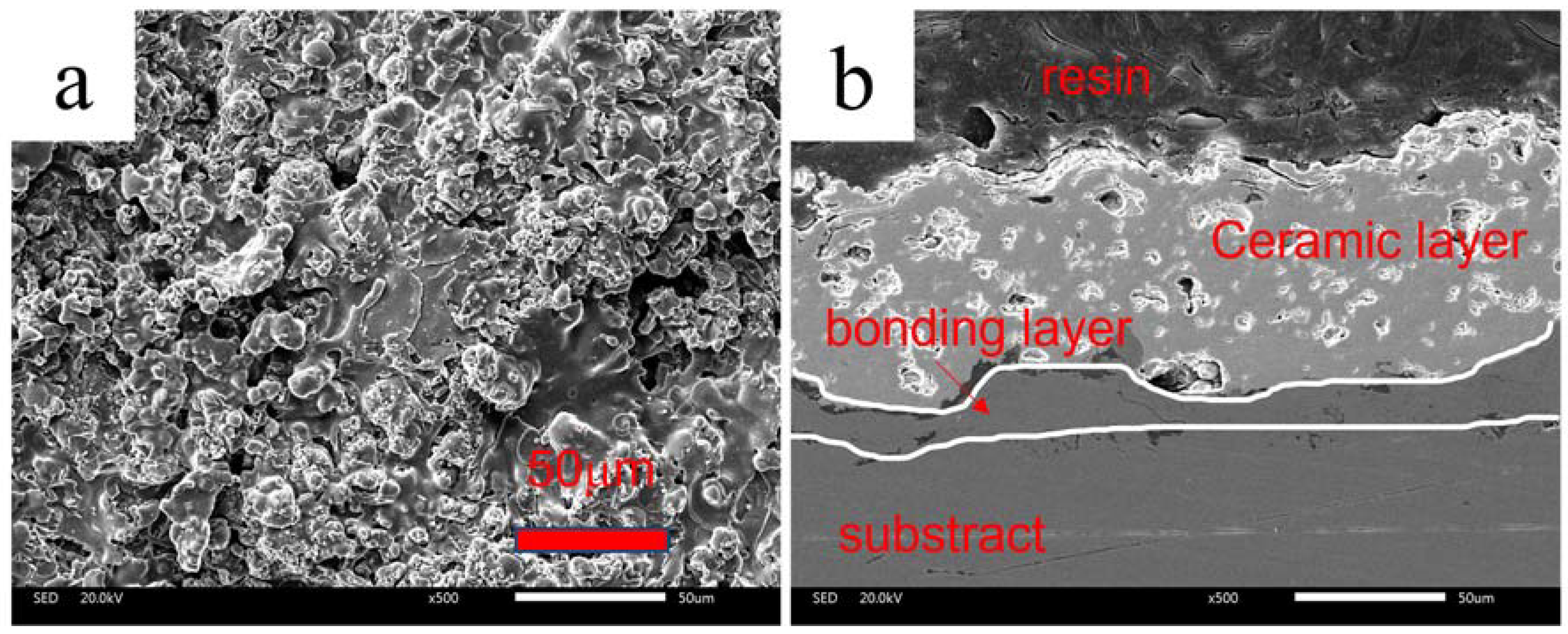
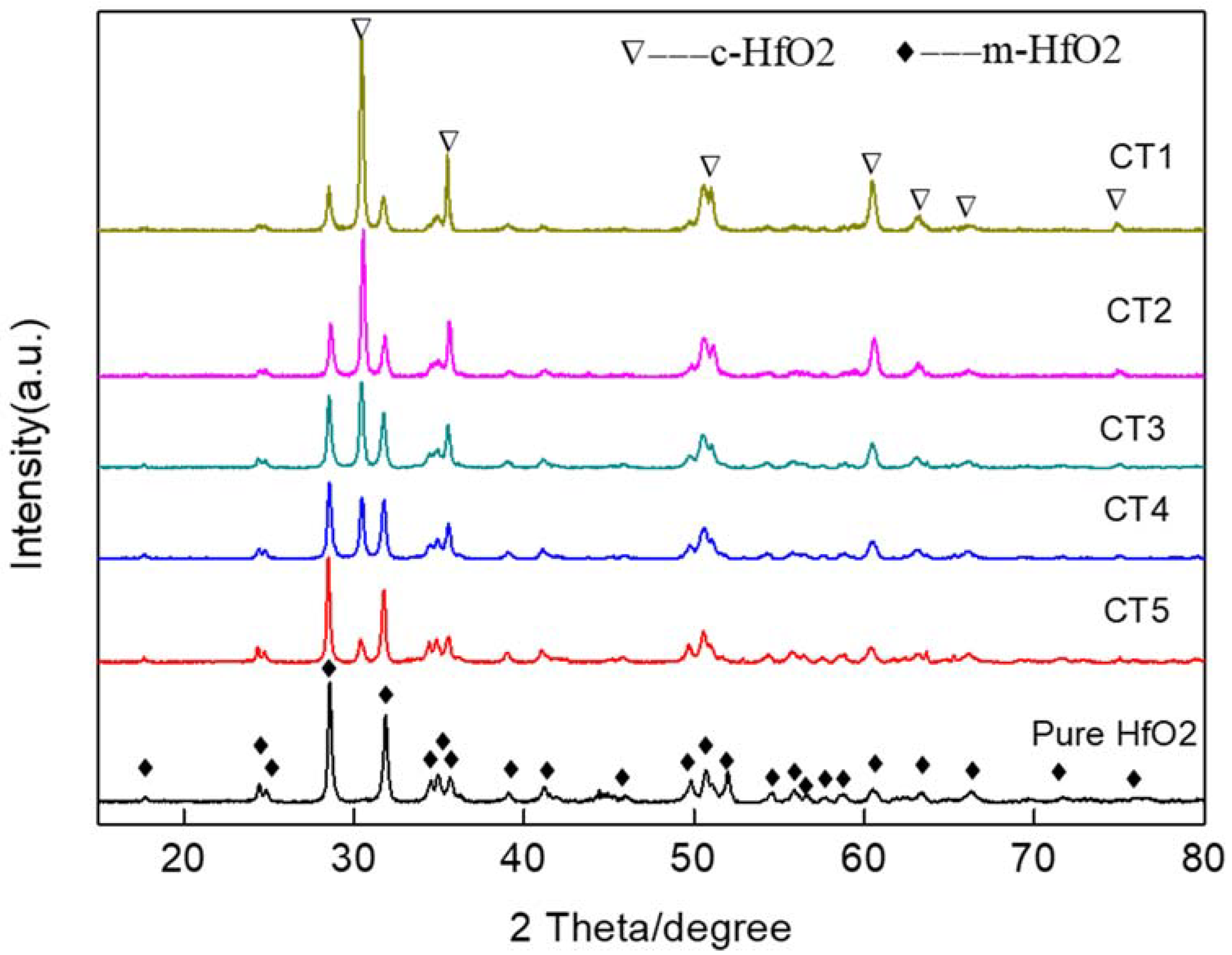
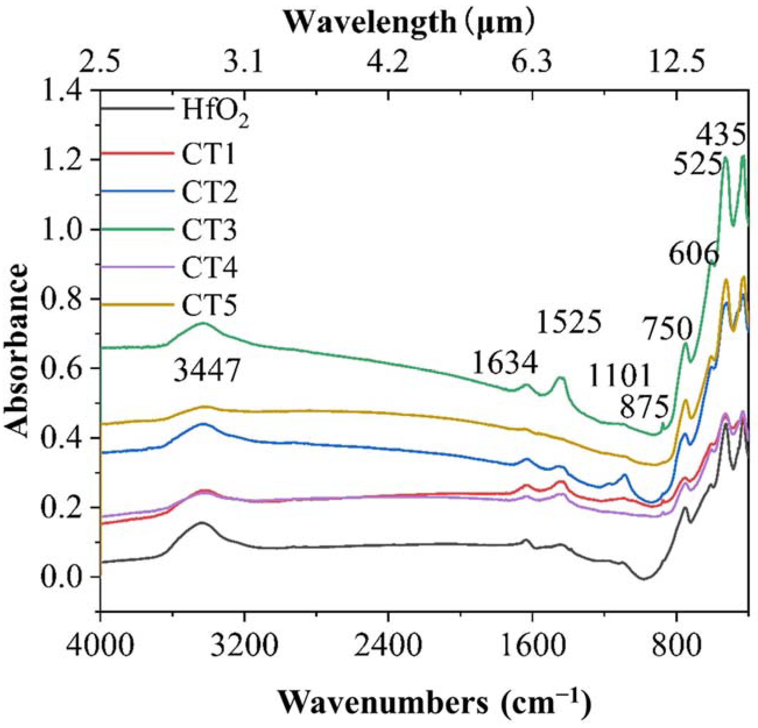
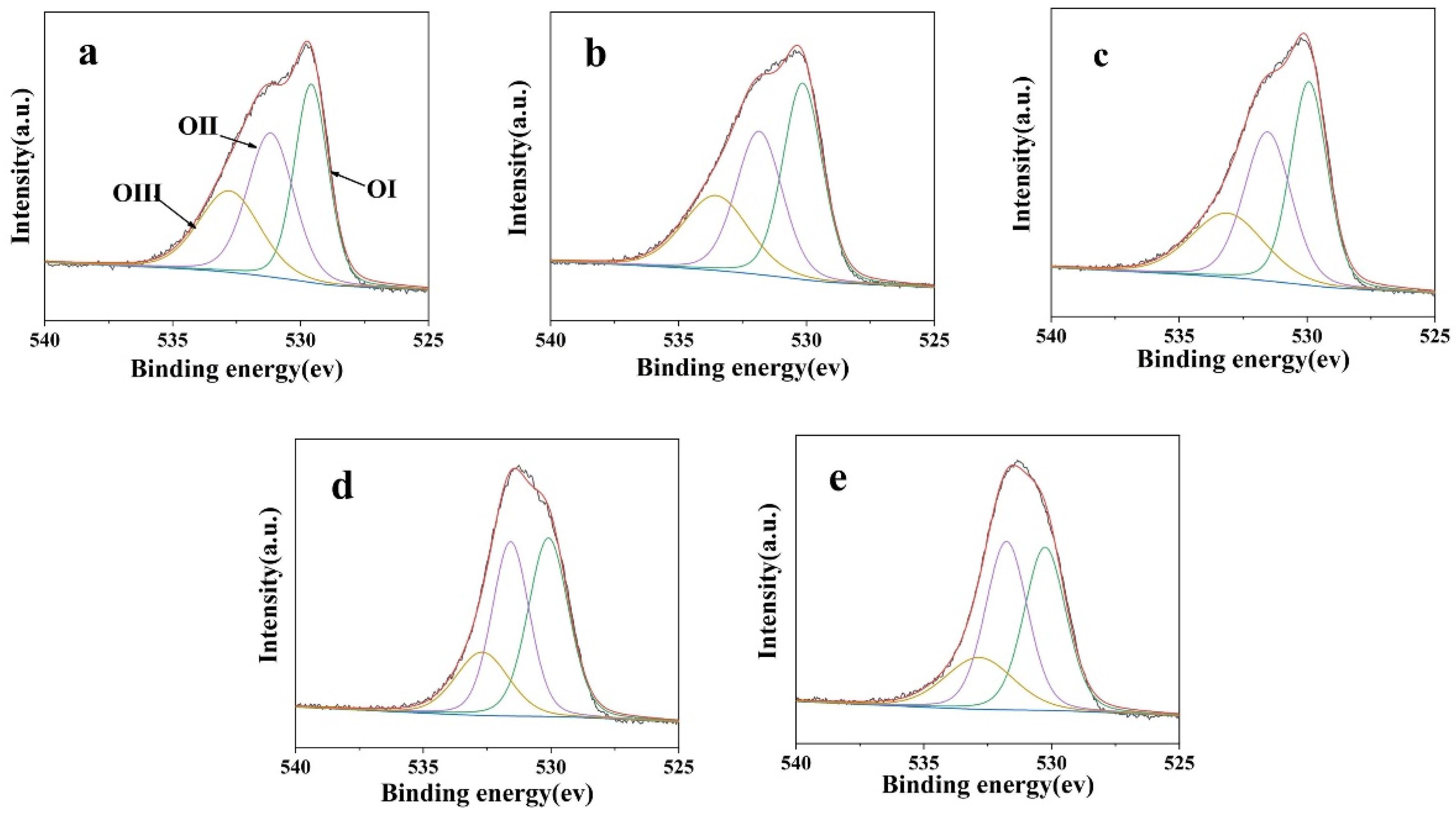
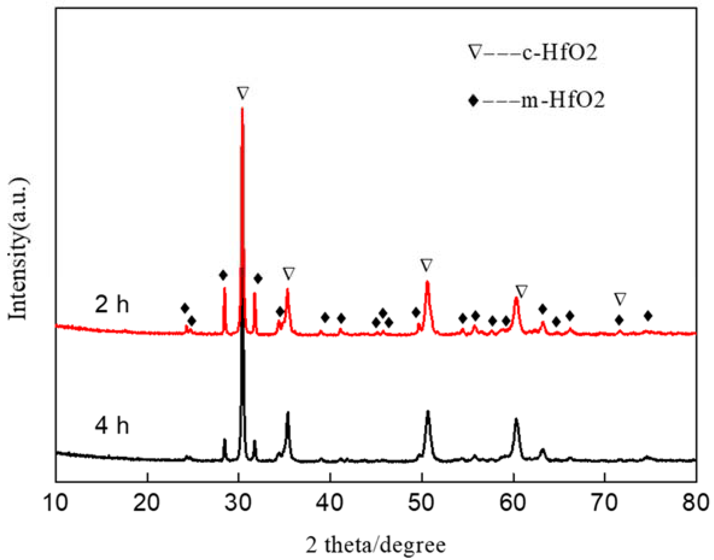
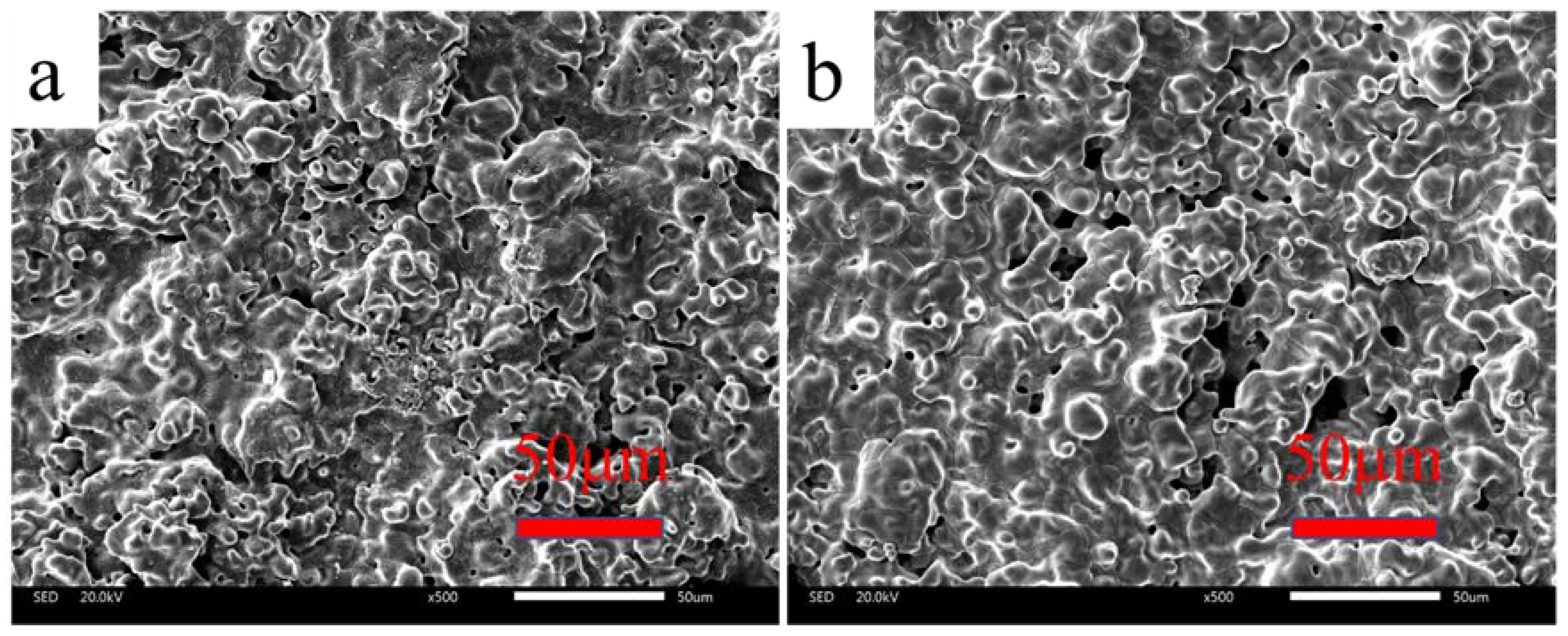
3.1. Microstructure and Chemical Composition

The surface and cross-section morphologies of the prepared HfO2-based coatings were observed via scanning electron microscopy. Based on the SEM images, the coatings had almost a similar microstructure. For instance, Figure 1 exhibits the surface and cross-sectional microstructures of the CT1 coating. It was found that the coating surface was porous with no apparent cracks, as shown in Figure 1a. The micropores were generated via insufficient melting and overlap of the ceramic droplets during the APS deposition. The cross-section microstructure of the coating is shown in Figure 1b. It was seen that the thickness of the metal coating was about 20~25 μm and the thickness of the ceramic coating was about 60~70 μm. The ceramic layer was tightly bonded to the metal layer. Moreover, some micropores were observed inside the ceramic layer, which were unavoidable during the thermal spraying. The micropores on the surface were beneficial for improving the light scattering area and projection depth, are were thought of as ideal black bodies to improve the absorption of infrared radiation [21].
The XRD patterns of the HfO2 coatings co-doped with different Ca/Tb atomic ratios are shown in Figure 2. It was found that the pure HfO2 coating was in a single-phase structure, which was monoclinic HfO2 phase (mHfO2: PDF no. 34-104). However, the HfO2 coatings doped with Ca/Tb were composed of two phases, which were monoclinic HfO2 (mHfO2: PDF no. 34-104) and cubic HfO2 (cHfO2: PDF no. 35-560). Commonly, there are three types of crystal structure for pure HfO2. The pure HfO2 is stabilized with a monoclinic phase at room temperature. When the temperature rises to about 1800 °C, the monoclinic phase will transfer to a tetragonal phase, and will continue to transfer to a cubic phase when the temperature is above about 2600 °C. However, according to the HfO2-rare Earth oxide (REO) binary phase diagram [22], it is found that doping Tb4+, Dy3+, Y3+, Ho3+, Er3+, Yb3+, and Lu3+ can stabilize the cubic phase even at room temperature. In this study, due to Ca and Tb ions entering the cubic HfO2 lattice, the cubic HfO2 phase was stabilized at a normal temperature. Furthermore, with the co-doping atomic ratio of Ca/Tb decreasing, the ratio of cubic HfO2 gradually reduced, implying a greater stabilizing effect of Ca than that of Tb. This was owing to a larger ionic radius of Ca2+ (0.99 Å) relative to Tb3+ (0.92 Å) [23], which produced larger lattice distortion and made it difficult to convert cubic HfO2 to monoclinic HfO2 during the drop in temperature after the APS deposition.
To further identify the chemical bonding of the prepared HfO2 coatings, FT-IR analysis was carried out. The infrared absorption spectra of the pure HfO2 and the CT1~CT5 coatings in the range of 4000~400 cm−1 are shown in Figure 3. It was seen that there was no significant difference in the absorption peaks among the un-doped HfO2 coating and the CT1~CT5 coatings. The main infrared absorption peaks occurred at 3447 cm−1, 1634 cm−1, 1525 cm−1, 1101 cm−1, 875 cm−1, 750 cm−1, 606 cm−1, 525 cm−1, and 435 cm−1. The absorption peaks near 3447 cm−1 and 1634 cm−1 were a result of the H-O bond vibration of H2O adsorbed by the coatings’ surfaces [24]. The infrared absorption peaks located at 1525 cm−1, 1101 cm−1, and 875 cm−1 corresponded to the multiplication and ensemble absorption of monoclinic HfO2 [25]. In the range of 800–400 cm−1, monoclinic HfO2 had strong and sharp infrared absorption peaks at 750 cm−1, 606 cm−1, 525 cm−1, and 435 cm−1 [26]. The monoclinic HfO2 possessed a lot of vibrational modes, which were beneficial for improving the infrared emissivity in the medium and far bands.

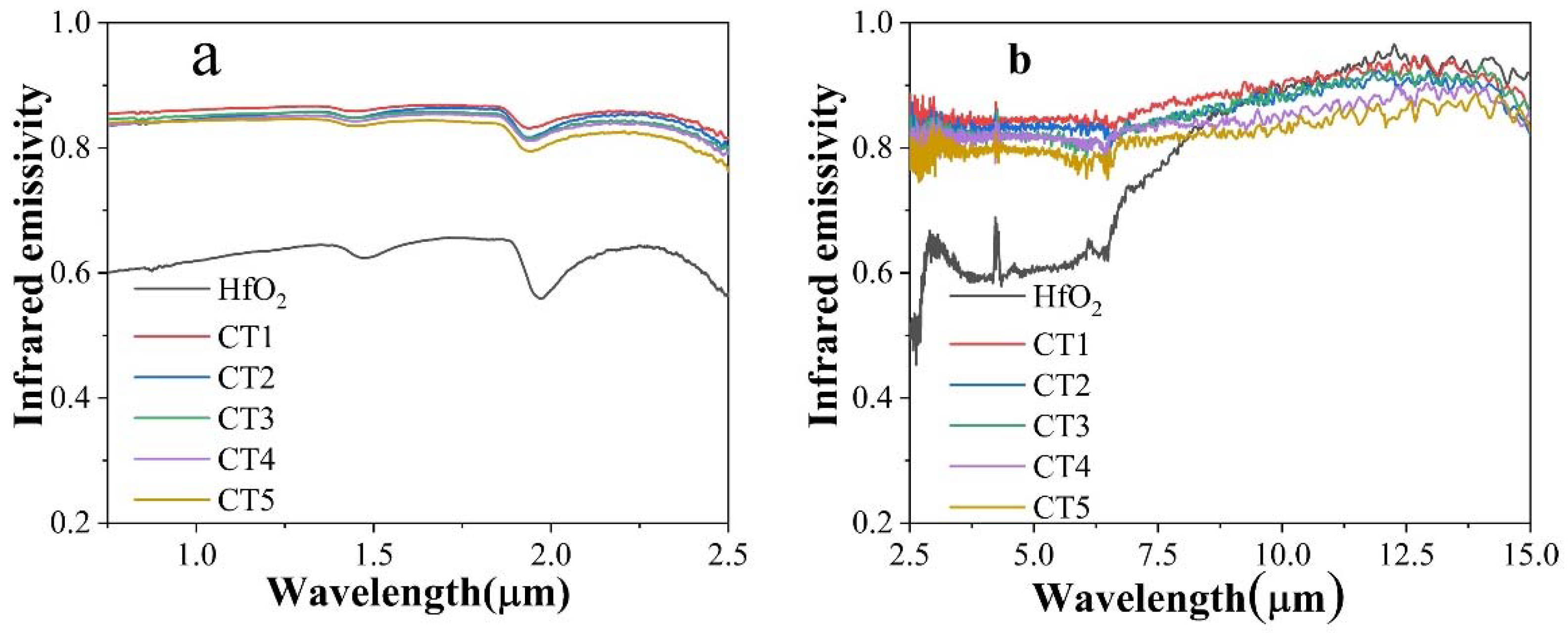
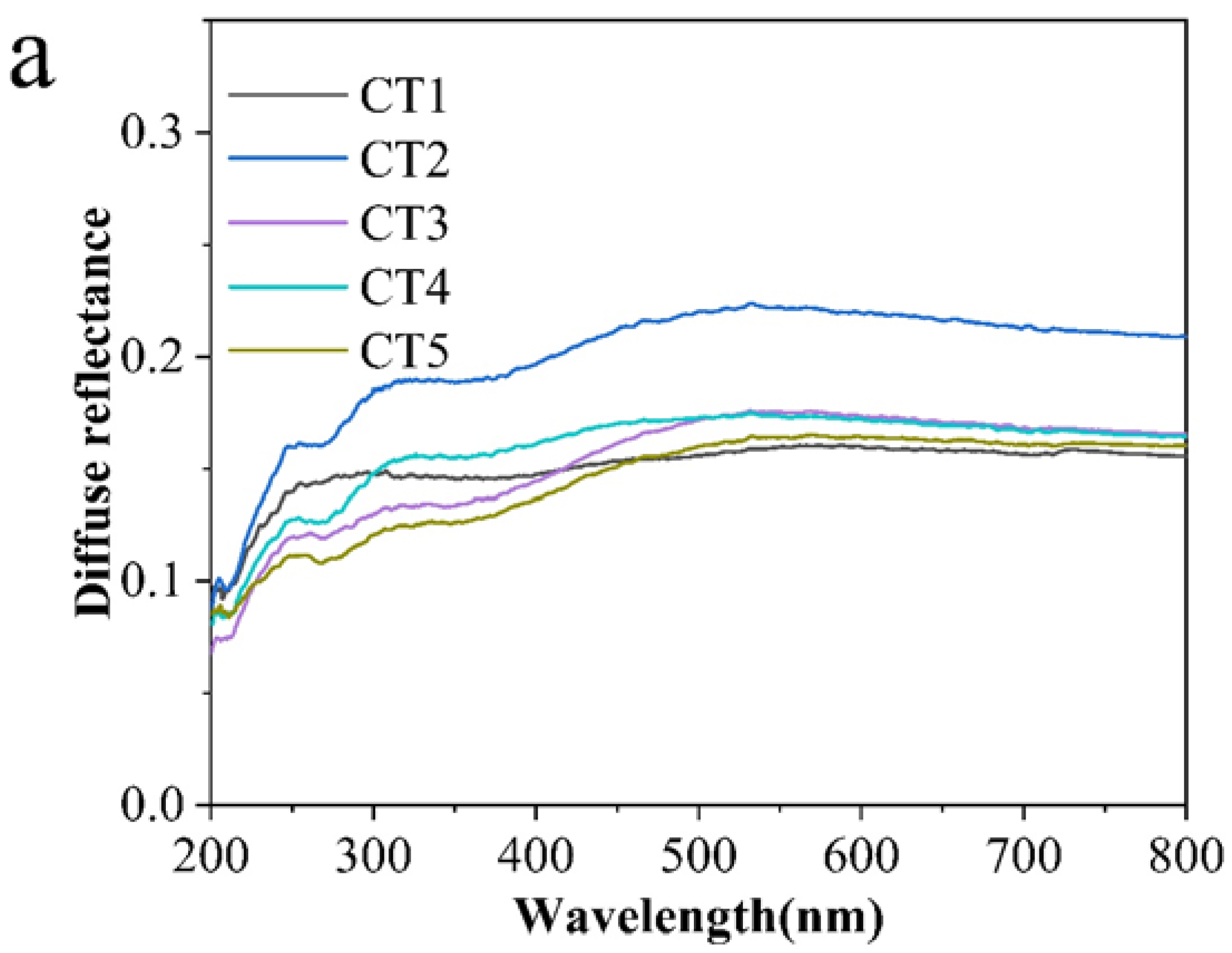
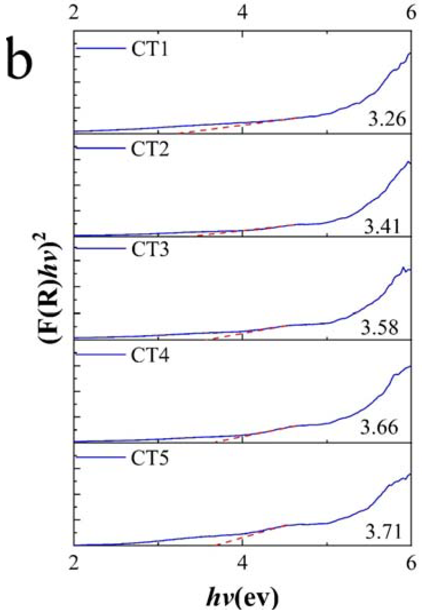
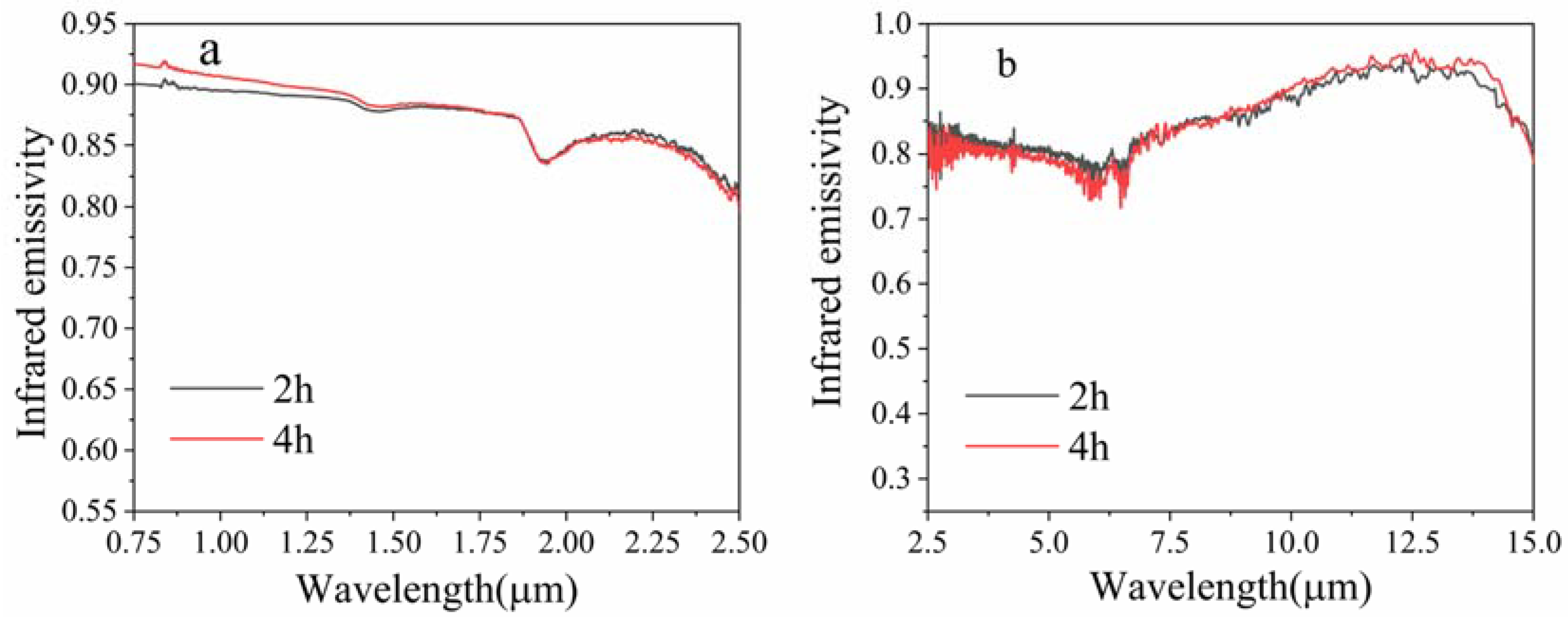
3.2. Room Temperature Infrared Radiation Property

The room temperature infrared spectral emissivity in the 0.75~2.5 μm band and the 2.5~15 μm band are shown in Figure 4a and Figure 4b, respectively. Based on Figure 4, the infrared spectral emissivity of the HfO2 coatings doped with Ca/Tb in both of the two bands was notably enhanced, compared to that of the un-doped HfO2 coating. The total infrared emissivity values of the HfO2 coatings in the 0.75~6.5 μm band and the 6.5~15 μm band were calculated referring to our former report [20]. The results are shown in Table 1. It is demonstrated that the total emissivity of the coatings in the 0.75~6.5 μm band and the 6.5~15 μm band decreased gradually with the decreasing of the Ca/Tb co-doping atomic ratios. Furthermore, except for the total emissivity of the CT5 coating in the 6.5~15 μm band which was slightly lower than that of the un-doped HfO2 coating, the total infrared emissivity of the doped coatings was more prominent. The best radiation performance occurred in the CT1 coating, whose total emissivity in the 0.75~6.5 μm band and the 6.5~15 μm band was 0.844 and 0.900, correspondingly. Comparing this with our previous work [20], the infrared emissivity in the 0.75~6.5 μm band was notably enhanced, and had improved from 0.820 to 0.844. The emissivity in the 6.5~15 μm band barely changed and was 0.900, almost the same as with 0.902.
As shown in Figure 4b, the spectral infrared emissivity of the doped HfO2 coatings was notably enhanced in the shorter wavelength band of 6.5~15 μm, while it decreased slightly in the longer wavelength band, compared with that of the un-doped HfO2 coating. Generally, infrared radiation above 10 μm for ceramics is mainly attributed to one-phonon processes, which are related to infrared fundamental frequency absorption. The radiation in 5~10 μm corresponds to multi-phonon processes, which are infrared sum frequency, double frequency, and difference frequency absorptions. On the one hand, doping Ca and Tb ions was beneficial to stabilize the cubic phase, which reduced the fundamental infrared absorption modes, weakening the lattice vibration absorption. On the other hand, Ca and Tb with large ionic radii entered the HfO2 lattice, increasing the lattice distortion and strengthening the lattice’s polar vibrational absorption. Since the approximate mass of Ca-O and Tb-O bonds was smaller than that of Hf-O bonds, the infrared absorption of lattice vibration shifted, favoring absorption below 10 μm. According to Table 1, it is indicated that the latter factor occupied the primary role that improved the total emissivity in the 6.5~15 μm band for the CT1~CT4 coatings. Moreover, Ca had a more significant strengthening effect than Tb due to a higher ionic radius and a smaller atomic mass. In contrast, for the CT5 coatings, the former factor played a dominant role that reduced the total emissivity in this band.
The changes in infrared emissivity in the 0.75~6.5 μm band were strongly concerned with the impurity levels and free carrier concentration [27]. The generation of impurity levels will shorten the forbidden bandwidth of the coating, which is beneficial to the transition of electrons from a valence band to conduction band, enhancing intrinsic absorption. Meanwhile, this also promotes the transition of free carriers from the conduction/valance band to impurity levels, enhancing the impurity level absorption. The band gap Eg of the coatings was measured referring to our former study [20]. The diffuse reflectance spectra in 200~800 nm of the coatings are shown in Figure 5a. The curves of (F(R)hv)2 against hv are shown in Figure 5b, where R is the diffuse reflectance, F(R) is the Kubelka–Munk function, and hv is the photon energy. By extending the straight-lined part to the x-axis, the value of hv extrapolated to F(R)hv = 0 was the measured Eg. All of the coatings after doping possessed a much lower Eg value compared with 5.27 eV of the pure HfO2 coating, that is 3.26 eV, 3.41 eV, 3.58 eV, 3.66 eV, and 3.71 eV for the CT1~CT5 coatings, respectively. In addition, by decreasing the co-doping atomic ratio of Ca/Tb, the band gap Eg gradually increased. This was related to the oxygen vacancies, which introduced impurity levels, reducing the forbidden bandwidth [28].
In order to characterize the oxygen vacancy, XPS was performed to identify the chemical states of oxygen in the coating. Figure 6a–e show the results of the XPS patterns for the O1s in the CT1~CT5 coatings, and it was seen that the doped HfO2-based coatings contained three kinds of oxygen. Among them, the OⅠ peaks at 529.6~530.2 eV represented the lattice oxygen, and the OⅡ peaks at 531.2~531.9 eV were from the oxygen chemically adsorbed at the oxygen vacancy position [29]. In addition, the OⅢ peaks at 532.7~533.5 eV corresponded to the adsorbed oxygen on the surface of the coating [30]. In the CT1, CT2, CT3, CT4, and CT5 coatings, the percentages of OⅡ peaks could be estimated through the area ratio, which were 41.2%, 40.6%, 40.2%, 38.2%, and 34.3%, respectively. As we mentioned in our former study, the low-valence Tb3+ and Ca2+ ions entered the HfO2 lattice and replaced the Hf4+ ions, generating oxygen vacancies. Since doping one Ca2+ would introduce one oxygen vacancy into the lattice, while doping one Tb3+ only introduced half an oxygen vacancy, the concentration of generated oxygen vacancy decreased with decreasing the atomic ratio of Ca/Tb. Consequently, an increasing trend of Eg was obtained, resulting in a decline in emissivity in 0.75~2.5 μm for the CT1~CT5 coatings.

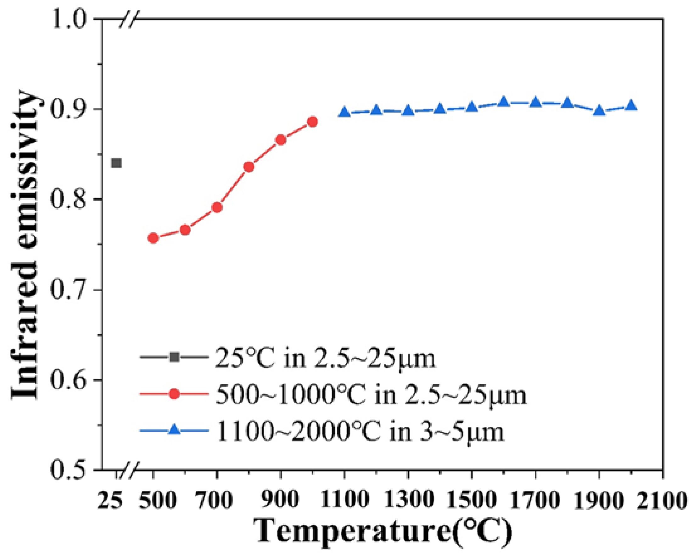
3.3. High-Temperature Infrared Radiation Performance

Based on the infrared performance results at room temperature, the CT1 coating was chosen as the optimal coating. The high-temperature infrared radiation property of the CT1 coating was investigated, and the results are shown in Figure 7. According to this, the total emissivity of the CT1 coating in the 2.5~25 μm band decreased from 25 °C to 500 °C. As the temperature rose to 500 °C, the peak wavelength of infrared radiation shifted from 9.7 μm to 3.7 μm based on Wien’s displacement law [31], and the proportion of energy in the short band increased. In addition, it was found that the infrared emissivity at 3.7 μm was smaller than that at 9.7 μm, as shown in Figure 4. Thus, the emissivity of the CT1 coating at 500 °C was lower than that at 25 °C.
In the range of 500~1000 ℃, the infrared emissivity increased as the temperature was raised. On the one hand, the peak wavelength of infrared radiation shifted from 3.7 μm to 2.5 μm, which had higher emissivity. On the other hand, the lattice vibration absorption was thermally strengthened [32]. When the temperature was raised to 1100 °C~2000 °C, the total emissivity of the CT1 coating in the 3~5 μm band remained basically unchanged, which was about 0.9. It was thought that the absorption/emission in this band at a high temperature was related to the intrinsic excitation, which was determined by the width of the energy level since the doping effect was weakened at a high temperature.

3.4. High-Temperature Thermal Stability

The XRD patterns of the CT1 coating after different times of heat treatment at 2000 °C are shown in Figure 8. This suggests that the coatings after heat treatment were still composed of two phases which were monoclinic HfO2 and cubic HfO2, indicating good thermal and chemical stability of the coating.
The microscopic surface morphologies of the CT1 coating held at 2000 °C for 2 h and 4 h in a vacuum environment are shown in Figure 9a and Figure 9b, respectively. The coatings’ surfaces were porous without cracks, and the surface roughness did not change significantly with the increase in holding time.
The infrared spectral emissivity of the CT1 coating in the 0.75~2.5 μm band and the 2.5~15 μm band after heat treatment is shown in Figure 10. In the 0.75~6.5 μm band, the total emissivity of 2 h and 4 h was 0.833 and 0.826, correspondingly, and therefore slightly lower than that before heat treatment. In the 6.5~15 μm band, the total infrared emissivity of the CT1 coatings after heat treatment was almost unchanged, and was 0.892 for 2 h and 0.895 for 4 h. The results suggest that the coating maintained good thermal stability at a high temperature.

4. Conclusions

HfO2 coatings co-doped with different atomic ratios of Ca/Tb were prepared via the APS method. The coatings were composed of a m-HfO2 phase and a c-HfO2 phase. Owing to the impurity levels and the heavy lattice distortion introduced by doping Ca and/or Tb, the free carrier absorption and lattice vibration absorption were enhanced. Therefore, the total infrared emissivity of the doped coatings significantly increased compared with that of the pure coating. Since doping Ca had a greater enhancing effect than doping Tb, the optimal coating was obtained with a Ca/Tb atomic ratio of 1/0 (CT1), whose room temperature emissivity was 0.844 in the 0.75~6.5 μm band and 0.900 in the 6.5~15 μm band, respectively.
In terms of high-temperature infrared radiation performance, the total emissivity of the CT1 coating in the 2.5~25 μm band at 500 °C was lower than that at room temperature, due to the peak wavelength shifting toward a short band as the temperature increased. However, it increased with an increasing temperature between 500 and 1100 °C, since the thermal activation played a dominant role. The total emissivity in the 3~5 μm band barely changed from 1100 °C to 2000 °C, remaining at about 0.9. The CT1 coating also exhibited good thermal stability, as its chemical composition and surface morphology were basically unchanged after heat treatment at 2000 °C for 4 h. The total infrared emissivity of the CT1 coating after heat treatment was 0.826 in the 0.75~6.5 μm band and 0.895 in the 6.5~15 μm band, slightly lower than that before heat treatment.

Author Contributions

Conceptualization, X.C. and X.Z.; methodology, J.Z.; software, X.T.; validation, C.H. and X.T.; formal analysis, J.Z.; investigation, J.Z. and X.T.; resources, X.Z. and Y.C.; data curation, Y.C.; writing—original draft preparation, J.Z.; writing—review and editing, X.Z.; visualization, J.Z.; supervision, Y.C.; project administration, X.Z.; funding acquisition, X.Z. All authors have read and agreed to the published version of the manuscript.

Funding

This work was financially supported by the National Natural Science Foundation of China (grant no. 52006159).

Institutional Review Board Statement

Not applicable.

Informed Consent Statement

Not applicable.

Data Availability Statement

The data presented in this study are available upon request from the corresponding author. The data are not publicly available due to restrictions of data management.

Conflicts of Interest

The authors declare no conflict of interest.

References

  1. Wang, G.; Chen, Z.; Pan, Z.; Tang, H. Development and Properties of Infrared High Radiation Energy-Saving Coatings for Industrial Furnace. IOP Conf. Ser. Mater. Sci. Eng. 2019, 252, 022058. [Google Scholar] [CrossRef]
  2. Yue, X.; Zhang, T.; Yang, D.; Qiu, F.; Wei, G.; Lv, Y. A robust Janus fibrous membrane with switchable infrared radiation properties for potential building thermal management applications. J. Mater. Chem. A 2019, 7, 8344–8352. [Google Scholar] [CrossRef]
  3. Tang, H.; Tao, W.; Wang, H.; Song, Y.; Jian, X.; Yin, L.; Wang, X.; Scarpa, F. High-performance infrared emissivity of micro-arc oxidation coatings formed on titanium alloy for aerospace applications. Int. J. Appl. Ceram. Technol. 2018, 15, 579–591. [Google Scholar] [CrossRef] [Green Version]
  4. Paul, A.; Jayaseelan, D.; Venugopal, S.D. UHTC composites for hypersonic applications. Am. Ceram. Soc. Bull. 2012, 91, 22–29. [Google Scholar] [CrossRef] [Green Version]
  5. Li, H.; Wang, Y.; Fu, Q. Ablation resistance of carbides-coated C/C composites. Adv. Surf. Eng. Mater. 2017, 33, 803–809. [Google Scholar] [CrossRef]
  6. Chu, Y.; Sun, W.; Tian, T.; Xiong, X.; Zhang, H. Effect of sintering additives on the sintering and ablation resistance of novel HfO2-ThO2 high-temperature multiphase oxides. Ceram. Int. 2023, 49, 18977–18987. [Google Scholar] [CrossRef]
  7. Ren, L.; Yang, L.; Zhang, S.; Li, H.; Zhou, Y.; Ai, D.; Xie, Z.; Zhao, X.; Peng, Z.; Liao, R.; et al. Largely enhanced dielectric properties of polymer composites with HfO2 nanoparticles for high-temperature film capacitors. Compos. Sci. Technol. 2021, 201, 108528. [Google Scholar] [CrossRef]
  8. Ding, Q.; Tan, X.; Jiang, L.; Fan, X.; He, B.; Wang, C.; Zhuo, X.; Zhou, K.; Zhang, X. High-temperature performances of Si-HfO2-based environmental barrier coatings via atmospheric plasma spraying. Ceram. Int. 2022, 48, 23127–23136. [Google Scholar] [CrossRef]
  9. Zhang, Z.; Park, Y.; Kim, D.H.; Xue, Z.; Ji, X.; Park, H.; Zhang, S.; Byon, E.; Koo, B.H. High-temperature oxidation performance of novel environmental barrier coating 50HfO2-50SiO2/YxYb(2−x)Si2O7 at 1475 °C. J. Eur. Ceram. Soc. 2023, 43, 1127–1140. [Google Scholar] [CrossRef]
  10. Khoshman, J.M.; Kordesch, M.E. Optical properties of a-HfO2 thin films. Surf. Coat. Technol. 2006, 201, 3530–3535. [Google Scholar] [CrossRef]
  11. Dubinov, A.; Kitaev, I. Generalized Wien’s displacement law and Stefan–Boltzmann law for thermal radiation with a nonzero chemical potential. J. Opt. Technol. 2018, 6, 314–316. [Google Scholar] [CrossRef]
  12. Zhang, Y.; Wang, L.; Duan, Y.; Liu, B.; Liang, J. Preparation and performance of Ce-doped far-infrared radiation ceramics by single iron ore tailings. Ceram. Int. 2022, 48, 11709–11717. [Google Scholar] [CrossRef]
  13. Zhang, K.; Deng, Y.; Yang, Y.; Liao, Y.; Wang, B.; Gong, B.; Yang, W. Effect of lanthanum doping on the far-infrared emission property of vanadium–titanium slag ceramic. RSC Adv. 2017, 7, 13509–13516. [Google Scholar] [CrossRef]
  14. Liu, J.; Meng, J.; Liang, J.; Duan, X.; Huo, X.; Tang, Q. Effect of rare earth Ce on the far infrared radiation property of iron ore tailings ceramics. Mater. Res. Bull. 2015, 66, 26–31. [Google Scholar] [CrossRef]
  15. Umezawa, M.; Kurahashi, H.; Nigoghosian, K.; Okubo, K.; Soga, K. Designing Er3+/Ho3+-Doped Near-Infrared (NIR-II) Fluorescent Ceramic Particles for Avoiding Optical Absorption by Water. J. Photopolym. Sci. Technol. 2022, 35, 9–16. [Google Scholar] [CrossRef]
  16. Liu, L.; Zhang, S.; Ma, Z.; Zhu, S. Effects of Ca2+-Sr2+ doping on the infrared emissivity of LaCrO3. Ceram. Int. 2020, 46, 19738–19742. [Google Scholar] [CrossRef]
  17. Liu, F.; Cheng, X.; Mao, J.; Li, Q.; Zeng, X. Effects of rare-earth oxide doping on the thermal radiation performance of HfO2 coating. Ceram. Int. 2019, 45, 13004–13010. [Google Scholar] [CrossRef]
  18. De Souza, E.F.; Appel, L.G. Oxygen vacancy formation and their role in the CO2 activation on Ca doped ZrO2 surface: An ab-initio DFT study. Appl. Surf. Sci. 2021, 553, 149589. [Google Scholar] [CrossRef]
  19. Wang, H.; Sun, T.; Chang, L.; Liu, F.; Liu, B.; Zhao, C.; Xue, X.; Xiong, X. Preparation of Ca doping ZrO2 coating on NiTi shape memory alloy by cathodic plasma electrolytic deposition and its structure, in-vitro bioactivity and biocompatibility analysis. Surf. Coat. Technol. 2017, 325, 136–144. [Google Scholar] [CrossRef]
  20. Zeng, X.; Tong, X.; Liu, Z.; Xiong, Y.; Cao, Q.; Cheng, X. Fabrication and investigation of Ca/Tb co-doped HfO2 infrared coatings. J. Eur. Ceram. Soc. 2022, 42, 3542–3549. [Google Scholar] [CrossRef]
  21. Ng, H.W.; Gan, Z. A finite element analysis technique for predicting as-sprayed residual stresses generated by the plasma spray coating process. Finite Elem. Anal. Des. 2005, 41, 1235–1254. [Google Scholar] [CrossRef]
  22. Andrievskaya, E.R. Phase equilibria in the refractory oxide systems of zirconia, hafnia and yttria with rare-earth oxides. J. Eur. Ceram. Soc. 2008, 28, 2363–2388. [Google Scholar] [CrossRef]
  23. Rahm, M.; Hoffmann, R.; Ashcroft, N.W. Atomic and Ionic Radii of Elements 1–96. Chem. Eur. J. 2016, 22, 14625–14632. [Google Scholar] [CrossRef]
  24. Chen, C.; Zhao, C.; Zhou, X.; Chen, J. DFT study on the interaction of H2O and O2 with α-Fe2O3 (001) surface. Vacuum 2021, 188, 110164. [Google Scholar] [CrossRef]
  25. Auerhammer, J.M.; Eliel, E.R. Frequency doubling of mid-infrared radiation in gallium selenide. Opt. Lett. 1996, 21, 773–775. [Google Scholar] [CrossRef]
  26. Sturm, J.C.; Reaves, C.M. Silicon temperature measurement by infrared absorption. Fundamental processes and doping effects. IEEE Trans. Electron Devices 1992, 39, 81–88. [Google Scholar] [CrossRef]
  27. Martins, G.M.; Siqueira, K.; Fantini, C. New insight on the use of diffuse reflectance spectroscopy for the optical characterization of Ln2Ge2O7 (Ln = lanthanides) pyrogermanates. J. Lumin. 2021, 238, 118312. [Google Scholar] [CrossRef]
  28. Foster, A.S.; Lopez Gejo, F.; Shluger, A.L.; Nieminen, R.M. Vacancy and interstitial defects in hafnia. Phys. Rev. B 2002, 65, 174117. [Google Scholar] [CrossRef] [Green Version]
  29. Zhang, L.; Liu, Y.; Fang, X.; Cheng, Y. Regulating oxygen species for promoted deep oxidation of toluene: A comparative study of adsorbed oxygen and lattice oxygen. Fuel 2022, 321, 124116. [Google Scholar] [CrossRef]
  30. Chen, D.; Zhong, L.; Liu, F.; Liu, J.; Yu, J.; Wan, G.; He, S.; Luo, Y. Investigation of the role of surface lattice oxygen and bulk lattice oxygen migration of cerium-based oxygen carriers: XPS and designed H2-TPR characterization. Appl. Catal. B 2017, 218, 249–259. [Google Scholar] [CrossRef]
  31. Das, R. Wavelength- and Frequency-Dependent Formulations of Wien’s Displacement Law. J. Chem. Educ. 2015, 92, 1130–1134. [Google Scholar] [CrossRef]
  32. Han, R.; Tariq, N.; Liu, H. Development of high infrared emissivity porous ceramic coating using pre-synthesized flower-like CeO2 powder for high temperature applications. Ceram. Int. 2022, 48, 1340–1348. [Google Scholar] [CrossRef]
Figure 1. Surface morphology (a) and cross-section morphology (b) of CT1 coating.
Coatings 13 01386 g001
Figure 2. XRD patterns of HfO2 coatings co-doped with different Ca/Tb atomic ratios.
Coatings 13 01386 g002
Figure 3. FT-IR spectra of un-doped HfO2 coating and Ca/Tb-doped HfO2 coatings.
Coatings 13 01386 g003
Figure 4. Room temperature infrared spectral emissivity of un-doped HfO2 coating and Ca/Tb-doped HfO2 coatings in the range of (a) 0.75~2.5 μm and (b) 2.5~15 μm.
Coatings 13 01386 g004
Figure 5. Diffuse reflectance spectra (a) and (F(R)hv)2 against hv curves (b) of the prepared CT1~CT5 coatings.
Coatings 13 01386 g005aCoatings 13 01386 g005b
Figure 6. XPS spectra results of O1s for (a) CT5, (b) CT4, (c) CT3, (d) CT2, and (e) CT1 coatings, Yellow color for OⅢ, pink color for OⅡ, and green color for OⅠ.
Coatings 13 01386 g006
Figure 7. High-temperature infrared emissivity of CT1 coating.
Coatings 13 01386 g007
Figure 8. XRD patterns of CT1 coating after heat treatment of 2000 °C.
Coatings 13 01386 g008
Figure 9. Surface morphology of CT1 coating after heat treatment of 2000 ℃ with different holding times: (a) 2 h, (b) 4 h.
Coatings 13 01386 g009
Figure 10. Infrared spectral emissivity of CT1 coating after heat treatment in the range of (a) 0.75~2.5 μm and (b) 2.5~15 μm.
Coatings 13 01386 g010
Table 1. Total infrared emissivity of HfO2-based coatings in 0.75–6.5 μm and 6.5–15 μm bands.
Number0.75~6.5 μm6.5~15 μm
HfO20.6180.870
CT10.8440.900
CT20.8320.880
CT30.8200.884
CT40.8110.872
CT50.7850.865
Disclaimer/Publisher’s Note: The statements, opinions and data contained in all publications are solely those of the individual author(s) and contributor(s) and not of MDPI and/or the editor(s). MDPI and/or the editor(s) disclaim responsibility for any injury to people or property resulting from any ideas, methods, instructions or products referred to in the content.

