Article

Microstructure and Properties of FeCrMnxAlCu High-Entropy Alloys and Coatings

1
School of Materials and Engineering, Lanzhou University of Technology, Lanzhou 730050, China
2
State Key Laboratory of Advanced Processing and Recycling of Nonferrous Metals, Lanzhou University of Technology, Lanzhou 730050, China
*
Author to whom correspondence should be addressed.
Coatings 2023, 13(8), 1401; https://doi.org/10.3390/coatings13081401
Submission received: 13 July 2023 / Revised: 30 July 2023 / Accepted: 4 August 2023 / Published: 9 August 2023
(This article belongs to the Special Issue Cold Spray Deposition of Coatings, Novelties and Applications)

Abstract

:
FeCrMnxAlCu (x = 0.5, 1, 1.5, and 2) high-entropy alloys (HEA) and coatings were prepared through vacuum arc melting and cold spray-assisted induction remelting processes. This study investigated the effect of different Mn contents on the microstructure and wear resistance of HEAs and coatings. The results showed that the high-entropy FeCrMnxAlCu alloy prepared through vacuum arc melting and cold spray-assisted induction remelting processes comprised simple body-centered cubic and face-centered cubic phases with dendritic + interdendrite structures. The coating of the prepared alloys exhibited superior performance compared with the cast alloy. In addition, the hardness of the FeCrMnxAlCu HEA coatings synthesized through induction remelting was 1.4 times higher than that of the cast FeCrMnxAlCu HEA. Moreover, the wear rate of induction-remelted produced HEA coating was reduced by 24% compared with that of vacuum arc-melted produced HEA. The hardness of the induction-remelted produced FeCrMnxAlCu HEA coating initially increased and then decreased with increasing Mn contents. At x = 1, the hardness of FeCrMnAlCu HEA coating reached a maximum value of 586 HV, with a wear rate of 2.95 × 10⁻⁵ mm3/(N·m). The main wear mechanisms observed in the FeCrMnxAlCu HEA coatings were adhesive, abrasive, and oxidative.

1. Introduction

High-entropy alloys (HEAs) exhibit thermodynamic high-entropy, sluggish kinetic diffusion, structural lattice distortion, and performance cocktail effects [1,2,3]. In addition, HEAs have excellent properties, showing high strength, high hardness (45% and 56% higher than 45 # steel, respectively) [4,5], wear resistance, corrosion resistance, and high-temperature oxidation resistance (54%, 68%, and 32% higher than Al alloy, respectively) [6,7,8], compared with traditional metal materials. As a result, HEAs are widely used in surface engineering [9].
Manganese (Mn) is an inexpensive metallic element that is abundant and readily available in the Earth’s crust, and it is widely used as an alloying element [10]. Manganese (Mn) is often chosen as one of the primary elements when designing the composition of HEAs. Some researchers have used several cost-effective elements, such as Fe, Cr, Mn, Al, and Cu, as the main constituents of HEAs to fabricate FeCrMnAlCu-based HEAs with excellent properties using vacuum arc melting technology. Researchers have systematically investigated the effect of element variations on the properties of FeCrMnAlCu HEAs. For instance, Feng et al. [11] studied the effect of Fe content on the phase structure and mechanical properties of FexCrMnAlCu HEAs. The study revealed that FexCrMnAlCu HEAs were composed of dendritic and interdendritic structures. With the increase of Fe content, the strength hardness of the alloy decreases by 6%, 29%, respectively, and the plasticity increases by 12%. When x = 0.5, the precipitation-strengthening effect of intermetallic compounds in the alloy was more significant. With this composition, the FexCrMnAlCu HEA exhibited a hardness of 405 HV, compressive strength of 1428 MPa, yield strength of 978 MPa, and deformation rate of 0.16.
Currently, HEA coatings are mainly prepared using laser cladding, cold spraying, thermal spraying, magnetron sputtering methods, etc. Liu et al. [12] used laser cladding technology to prepare AlNbMoTaCux HEA coatings on the surface of Ti6Al4V. The effect of different Cu contents on the wear resistance of the coatings was studied. The results showed that as the Cu content increased, the BCC phase decreased, while the FCC phase increased in the coating, significantly improving coating toughness and decreasing the microhardness simultaneously. The wear resistance of AlNbMoTaCu0 coating was slightly improved by approximately 1.6 times that of the substrate, while that of the AlNbMoTaCu0.4 coating significantly improved. The wear resistance of AlNbMoTaCu0.4 improved by approximately 22 times that of the substrate. Yang et al. [13] synthesized AlCoCrCuFeNix HEA coatings through the cold spraying-assisted induction remelting method. The study revealed that the AlCoCrCuFeNix HEA coatings mainly comprised BCC and FCC phases with dendritic and interdendritic structures. As Ni content increased, the segregation of Cu was reduced, and when x = 0.5, the hardness of the coating was 534.7 HV. Feng et al. [14] investigated the effects of induction and laser remelting on the wear resistance performance of coatings. The wear mechanism of the cold spray-assisted induction remelting FeCrMnAlCu HEA coating during friction was mainly abrasive wear, and its wear rate was reduced by 29% compared with the wear rate of the cold spray-assisted laser remelting coating.
According to existing studies, the properties of the coating are better than those of the as-cast alloy. Therefore, this study prepared FeCrMnxAlCu (x = 0.5, 1, 1.5, and 2) HEAs and coatings using vacuum arc melting and cold spray-assisted induction remelting [15]. The effect of different Mn contents on the microstructure and wear resistance of FeCrMnxAlCu HEAs and coatings was investigated. The research results can expand the engineering application field of HEA coatings.

2. Materials and Methods

2.1. Preparation of HEAs through Vacuum Arc Melting

The raw materials used in the experiment are IRON(Fe), Chromium (Cr), Manganese Mn, Aluminum (Al), and Copper (Cu) metal particles (purity > 99.95%), and the weight of each sample is 20 g. Due to the volatility of Mn elements, an additional 3% to 5% Mn particles are added to each sample. The FeCrMnxAlCu HEA ingot was prepared by a non-consumable vacuum arc melting furnace in order to ensure the uniformity of the chemical composition of the ingot; each sample was turned over and melting was repeated at least 5 times.

2.2. Cold Spray-Assisted Induction Remelting HEA Coating Preparation

The raw materials used in this experiment were IRON(Fe), Chromium (Cr), Manganese Mn, Aluminum (Al), and Copper (Cu) commercial metal monomer powders (purity > 99.95%), which were mechanically mixed for 4 h (rotational speed: 14–24 rpm) and then used as raw materials for the cold sprayed mixed metal coatings. The samples were characterized following the previously reported experimental method [16]. The impurities, such as oil and dirt, on the substrate surface were ultrasonically cleaned with acetone before spraying. Then, the substrate surface was roughened with sandblasting. Low-pressure cold sprayed equipment (GDU-3-15, Russian State University of Science and Technology, Moscow, Russia) designed and manufactured by the Belarusian State Technical University was used to prefabricate FeCrMnxAlCu mixed metal coatings on the 10CrMo substrate. The mixed metal coating prepared using cold spraying was subjected to induction remelting to fabricate the HEA coating. The induction-remelting heating power ranged from 1.5 to 2.2 kW at a heating time of 15 to 20 s. The process for producing the FeCrMnAlCu HEA coating through cold spray-assisted induction remelting is illustrated in Figure 1.

2.3. Microstructural Characterization and Performance Testing of FeCrMnxAlCu HEAs and Coatings

A QuantaFEG450 field emission scanning electron microscope (SEM, JSM-5600LV, JEO, Akishima, Japan) was used to analyze the surface microscopic morphology and micro-area composition of the prefabricated mixed metal coatings and the HEA coatings. A transmission electron microscope (TEM, JEOL-2100F, Tokyo, Japan) was used to analyze the organization of the HEA and the coating. Using an HV1000 microhardness tester (JMHV-1000, Hong Kong, China) to measure the hardness of the specimen, the Vickers hardness was selected. When the applied load was 5 N and the dwell time on the surface of the specimen was 15 s, five points were selected on the surface of the specimen for measurement. Then, the average value was obtained. The UMT Tribolab friction equipment produced by the Bruker company of the United States (Minneapolis, MN, USA) was used to test the friction properties of the HEAs and coatings. The sample size of the HEAs and coatings was 20 mm × 20 mm × 5 mm, and the counterpart was φ6 mm Al2O3 sphere. The friction test was repeated three times, and the average value was recorded as the experimental result. The friction test parameters are set as follows: a test load of 7.5 N, friction stroke 3 mm, “f” is the sliding frequency 3 Hz, a test duration of 20 min. The wear rate of the coating can be calculated by the following formula [17]:
σ = v Σ w = A × L F × T × f × L × 2  
where “σ” is the wear rate (mm3/(N·m)), “v” represents the volume of friction skid mark, “w” is the accumulated frictional work (N·m), “A” is the cross-sectional area of wear, “L” is the abrasion mark length (mm), “F” is the applied load force (N), “f” is the sliding frequency (Hz).

3. Results and Discussion

3.1. Phase Composition of FeCrMnxAlCu HEAs and Coatings

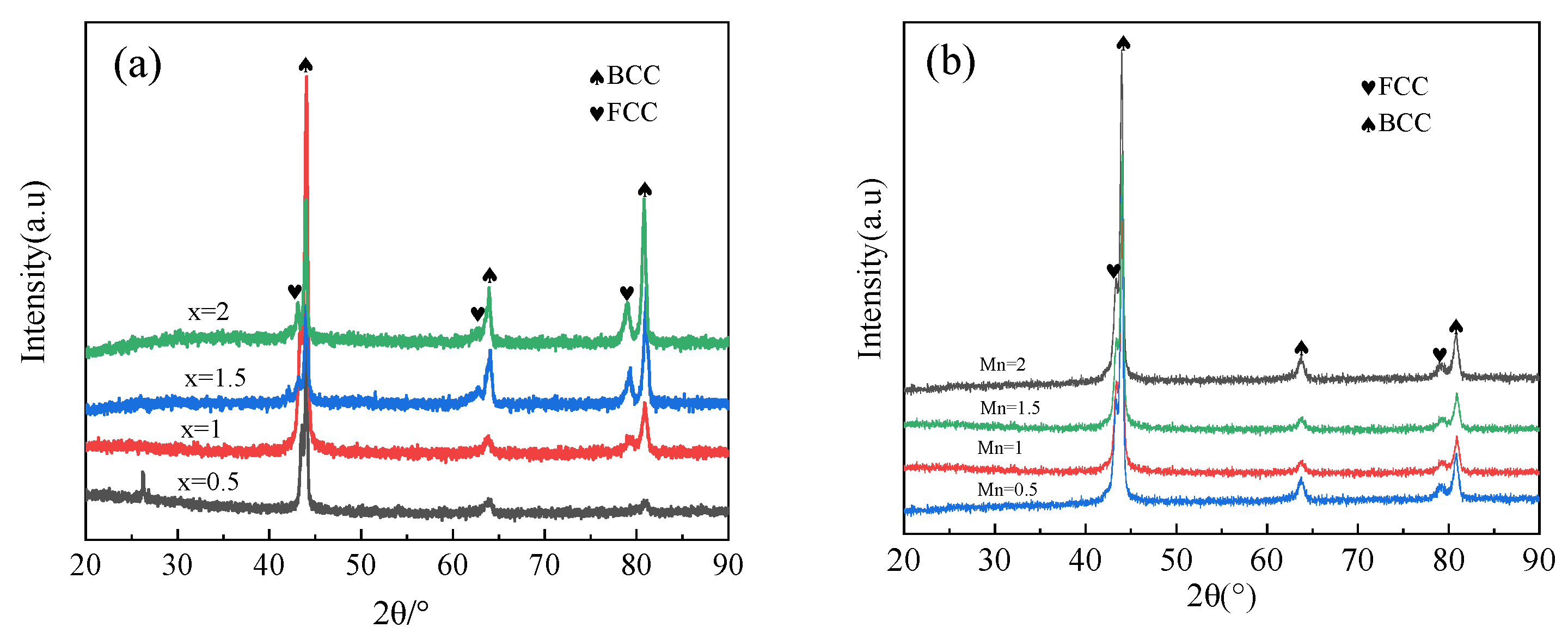
Figure 2a shows the XRD pattern of FeCrMnxAlCu HEAs prepared through vacuum arc melting. As shown in Figure 2a, the alloy comprised simple FCC and BCC phases. As the Mn content (x) increased from 0.5 to 2, no significant changes in the diffraction peaks of FeCrMnxAlCu HEA were observed, and the phase structure of the alloy maintained FCC + BCC phases. As Mn content increased, the diffraction peak intensity of the FCC phase in the FeCrMnxAlCu HEA gradually strengthened. This may be because the addition of Mn changes the geometric structure factor or atomic scattering factor of the unit cell and enhances the diffraction intensity of the unit cell to X-rays in some directions [18,19,20]. When Mn = 0.5, the lattice constants of both BCC and FCC phases were maximized. The lattice strains for the BCC and FCC phases were 0.72% and 3.76%, respectively, with an atomic size difference δ of 9.14%. Figure 2b shows the XRD pattern of the FeCrMnxAlCu HEA coating synthesized through the induction remelting process. As shown in Figure 2b, the coating comprised BCC and FCC phases, with maximum lattice constants for both BCC and FCC phases when Mn = 1. The lattice strain for the BCC phase was 0.84%, while that of the FCC phase was 3.85%. The atomic size difference δ was 9.36% in this case. The FeCrMnAlCu HEA coating had the largest atomic size difference δ, indicating a higher degree of lattice distortion. This atomic size difference suggests a more significant solid solution-strengthening effect in the BCC phase.

3.2. Microstructural Morphology of FeCrMnxAlCu HEAs and Coatings

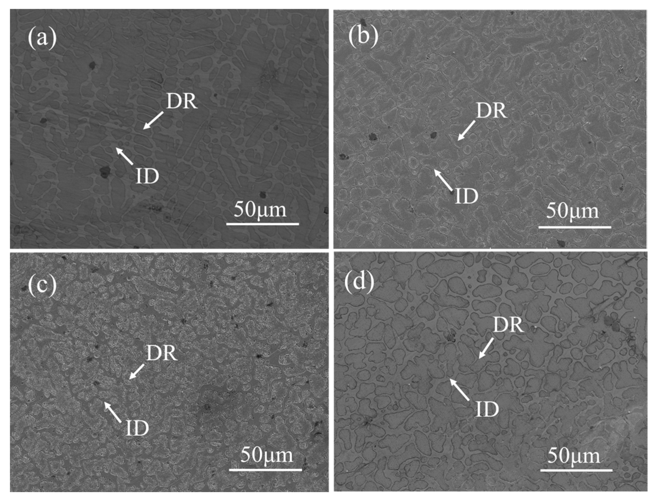
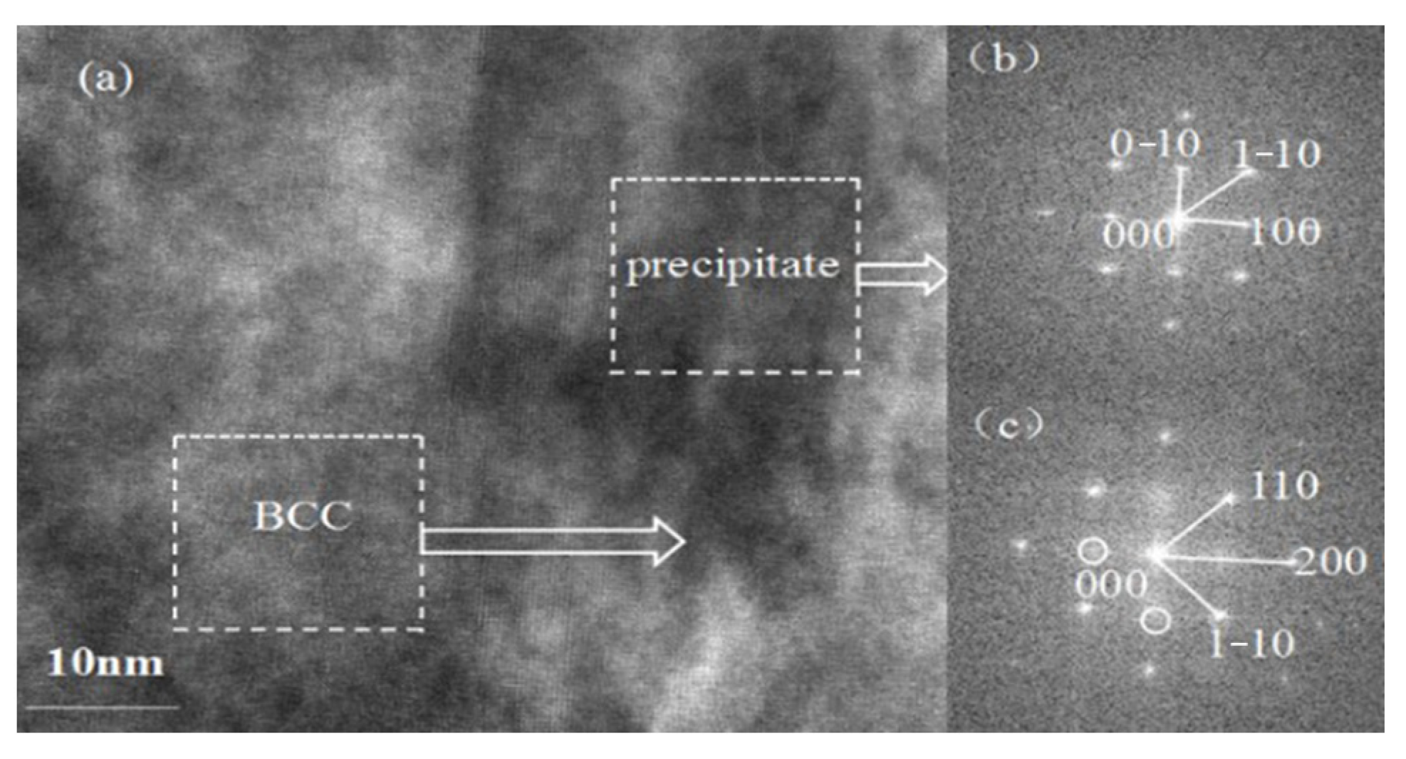
Figure 3 shows the SEM images of FeCrMnxAlCu HEAs prepared by vacuum arc melting. As shown in Figure 3a–d, the FeCrMnxAlCu HEA comprised gray dendritic and interdendritic structures and a black dendritic structure. The dendritic region (DR) was more pronounced, while the interdendritic region (ID) was relatively smaller. As Mn content increased, the DR continuously decreased, whereas the interdendritic region increased. When x = 2, the interdendritic region became maximum. Figure 4 shows the SEM micrographs of the surface of the FeCrMnxAlCu HEA coating synthesized through induction remelting. As in Figure 4a–d, the coating structure comprised DR + ID. With increasing Mn content, dendrites significantly increased, and grain size became relatively coarser. The increase of Mn element promotes the growth of dendrites. Figure 5 shows the TEM microstructure of the FeCrMnAlCu HEA prepared through vacuum arc melting. As shown in the figure, the phase structure of the FeCrMnAlCu HEA comprised FCC and BCC phases. The nano-twin boundaries between dendrites were almost eliminated, and the elongated precipitates on dendrites increased in size from about 130 nm to approximately 170 nm. The overall size of precipitates increased, and they were more uniformly distributed in the matrix. Figure 6 displays the HRTEM image and FFT pattern of the FeCrMnAlCu HEA. From the image, the FFT pattern further confirmed that the matrix maintained a disordered BCC structure. Moreover, precipitation particles exhibited an ordered BCC structure, with a coherent relationship between precipitate and matrix phases. Image pro plus software was used to statistically analyze the average particle size and volume fraction of precipitate phases on the BCC matrix in the FeCrMnAlCu HEA. As Mn content increased, the particle size of precipitate phases initially increased and then decreased, whereas the volume fraction decreased and then increased. When Mn content was x = 1, the average particle size of the precipitate phases in HEA dendrites became the largest, with a minimum volume fraction occupied. The BCC phase exhibited a minor degree of lattice distortion. In addition, the induction-remelted produced HEA coating rapidly solidified without compound precipitation, resulting in a more significant lattice distortion in the BCC phase. Therefore, the induction-remelting HEA coating exhibits a more significant lattice distortion, with a considerable solid solution-strengthening effect in the BCC phase.
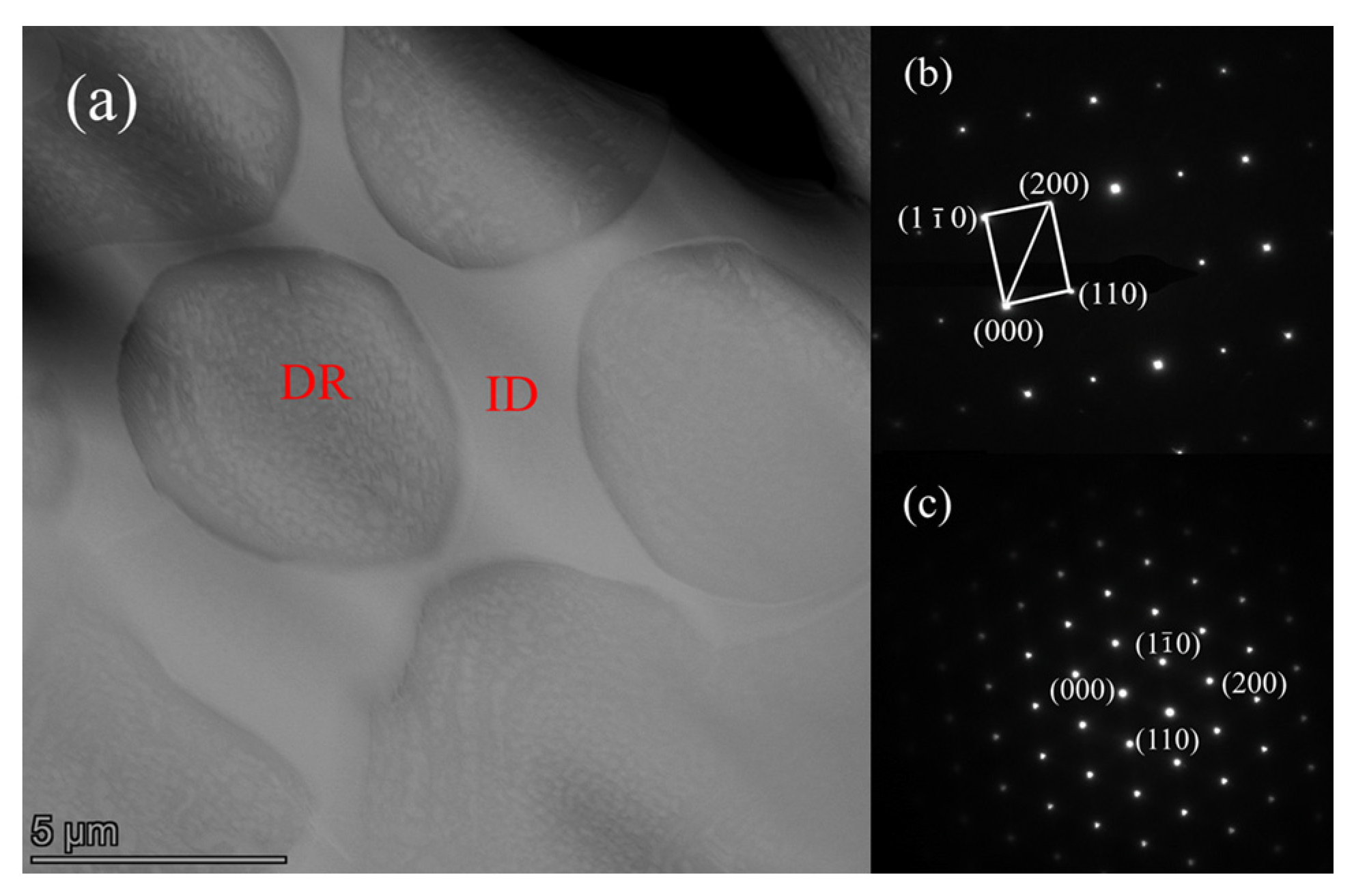
Figure 7 shows the TEM microstructure and high-angle annular dark-field analysis of the induction-remelting FeCrMnAlCu HEA coating. Figure 7a shows the microstructure of the FeCrMnAlCu HEA coating captured by high-angle annular dark-field imaging. The captured image revealed that the high-entropy alloy coating comprised DR with a BCC phase structure and IDRs with an FCC phase structure. Figure 7b,c show the diffraction patterns of BCC and FCC phases close to the grain boundaries of the FeCrMnAlCu coating. The dendrites in the FeCrMnAlCu coating exhibited a BCC phase structure, which was confirmed by the diffraction pattern along the [111] crystalline band. The interdendritic regions of FeCrMnAlCu coating exhibited an FCC phase structure, and the [011] crystalline band axis diffraction pattern confirmed that the interdendritic microstructure was a typical FCC phase twin structure.

3.3. Microhardness and Wear Resistance of FeCrMnxAlCu HEAs and Coatings

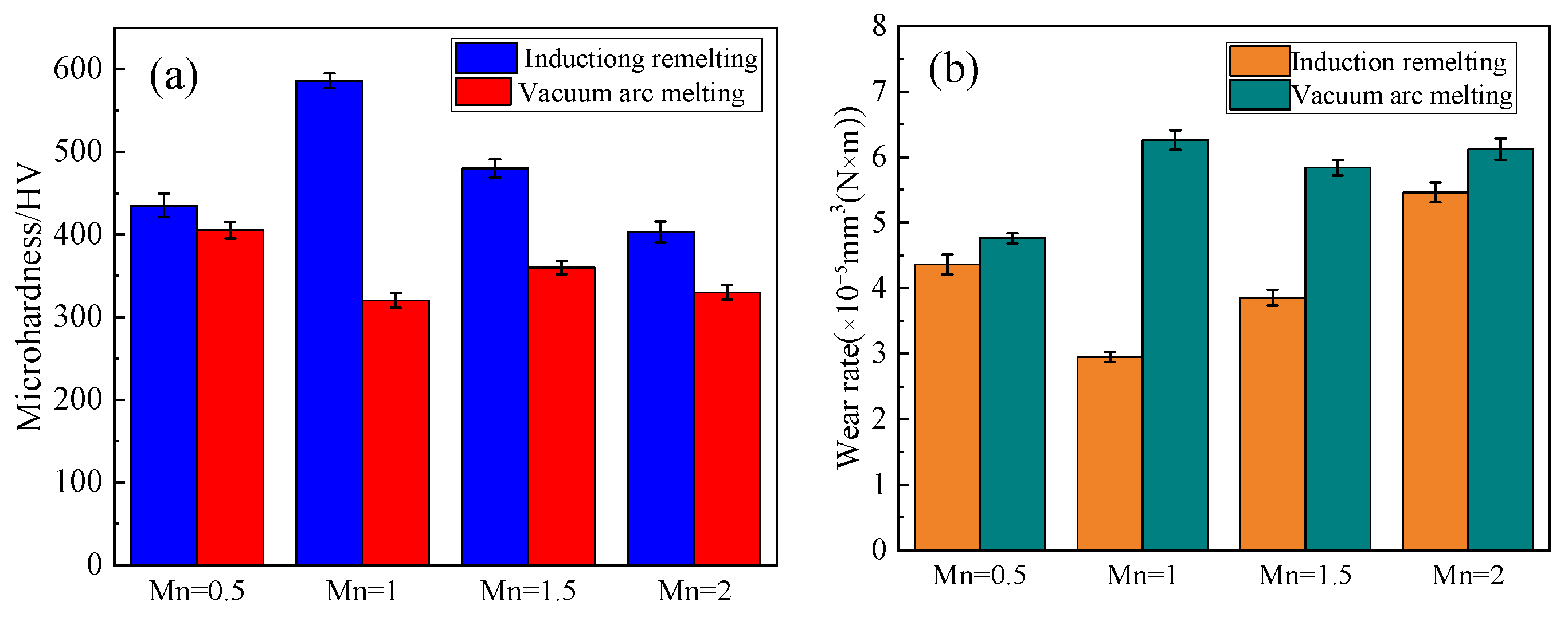
Figure 8 shows the microhardness and wear rate of the FeCrMnxAlCu HEAs and coatings prepared through vacuum arc melting and induction remelting. As shown in Figure 8a, the highest hardness of the FeCrMnxAlCu HEA prepared through vacuum arc melting was 405 HV. The maximum hardness of the FeCrMnxAlCu HEA coating synthesized through induction remelting was 586 HV, which is 1.4 times higher than that of the HEA prepared through vacuum arc melting. The main reason for the differences was that the vacuum arc melting process had a slower cooling rate, leading to the formation of precipitates in the alloy [21,22]. The lattice distortion of the BCC phase was relatively small in this case. However, the cooling rate of the induction remelting process for the HEA coating was relatively faster, and no other precipitate phases were observed, resulting in a larger lattice distortion in the BCC phase. The lattice distortion of the HEA coating synthesized through induction remelting was greater than that of the HEA fabricated through vacuum arc melting. Therefore, the FeCrMnxAlCu HEA coating exhibited significant solid solution strengthening, resulting in a higher coating hardness. As shown in Figure 8b, the FeCrMnxAlCu HEA prepared through vacuum arc melting exhibited a lower wear rate of 4.76 × 10⁻⁵ mm3/(N·m). In contrast, the minimum wear rate of the FeCrMnxAlCu HEA coating synthesized through induction remelting was 2.95 × 10⁻⁵ mm3/(N·m). The wear rate of the coating was reduced by 24% compared with that of the HEA fabricated through vacuum arc melting.
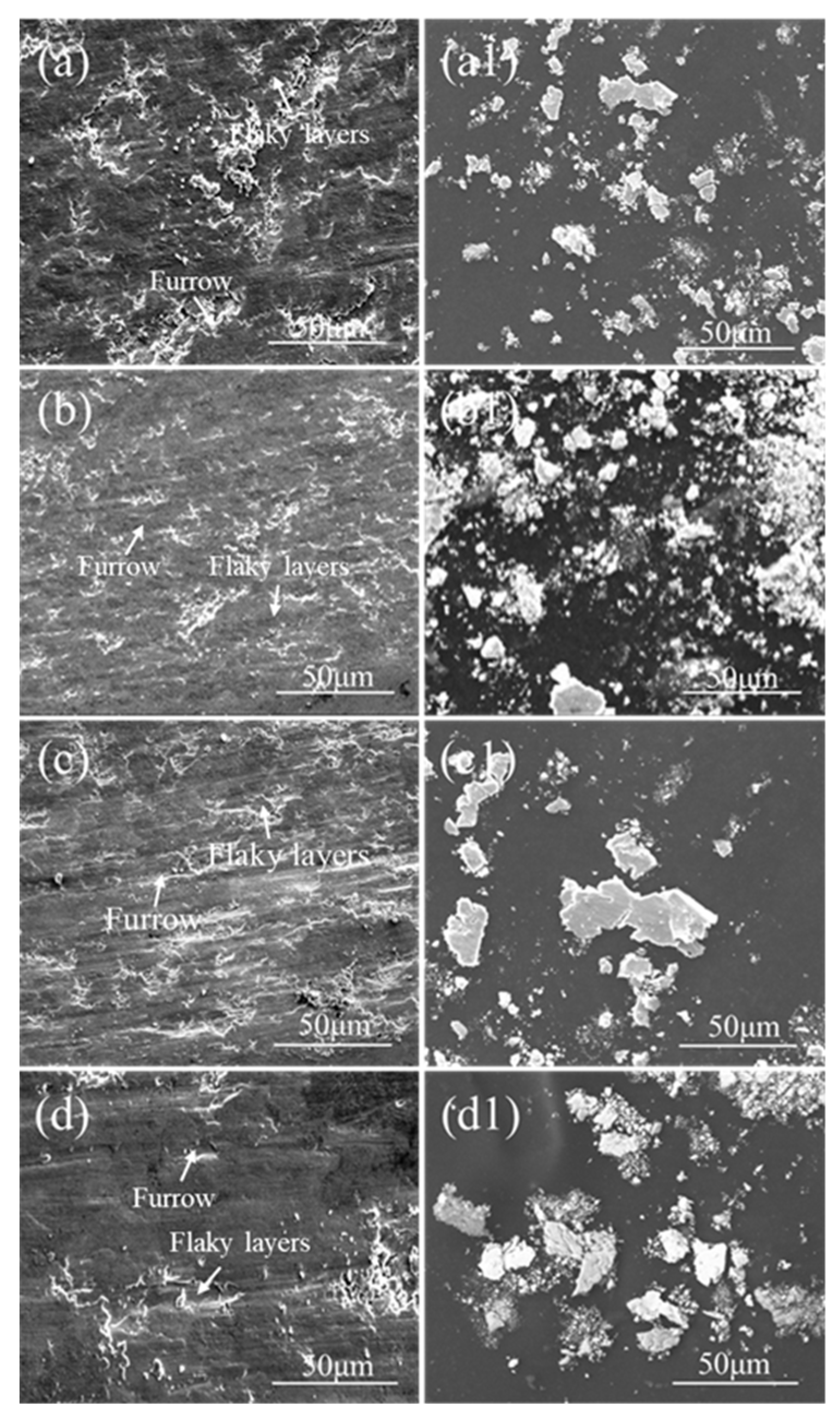
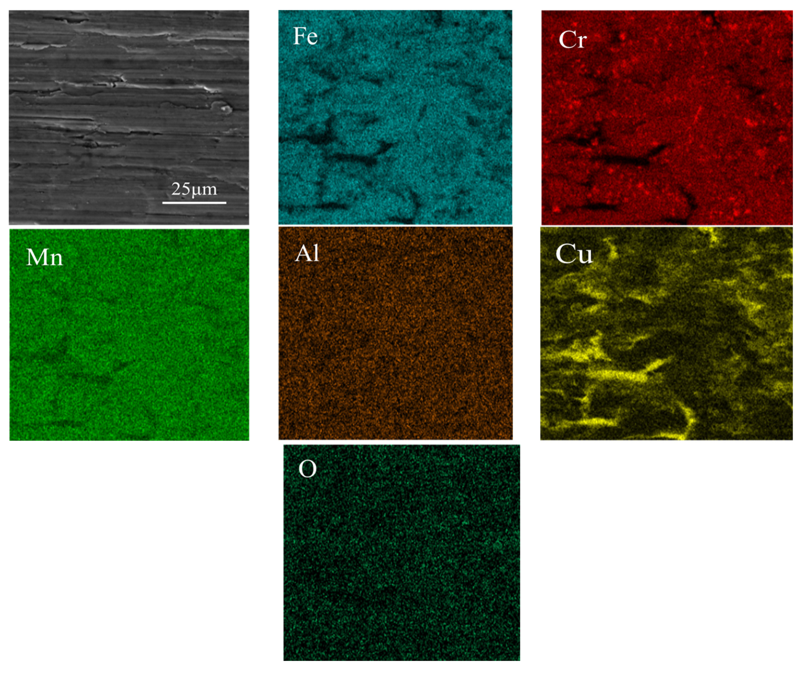
Figure 9a–d show the SEM images of the worn surfaces of the FeCrMnxAlCu HEA coatings, while Figure 9(a1–d1) displays the SEM images of the worn debris of the FeCrMnxAlCu HEA coatings. Figure 9a shows that when x = 0.5, the surface of the FeCrMn0.5AlCu HEA coating appears rough, with some long and narrow furrows along the sliding direction. Additionally, small amounts of lamellar layers were observed on the surface of the FeCrMn0.5AlCu HEA coating. Based on these observations, we inferred that the wear mechanisms of the FeCrMn0.5AlCu HEA coatings mainly involved adhesive wear and abrasive wear. Figure 9b shows that when x = 1, the surface of the friction coating becomes relatively smoother, with fewer and shallower furrows and a few adhesive layers. This phenomenon indicates that when Mn = 1, the adhesive wear and abrasive wear of the coating are significantly reduced [23,24]. When x = 1.5 and 2, the number and depth of furrows on the surface of the friction coating surface significantly increased, and a considerable amount of flaky delamination was observed (Figure 9c,d), indicating that the FeCrMn1.5AlCu and FeCrMn2AlCu HEA coatings underwent periodic delamination during friction. Furthermore, when x = 2, numerous spalling pits were observed on the surface of the friction coating, which contributed to the higher friction coefficient of the coating. Figure 9(a1–d1) show the SEM images of the worn debris of the FeCrMnxAlCu HEA coatings, the morphology of the debris is similar, and the particle size of the debris is similar. In conclusion, adhesive and abrasive wears were the main wear mechanisms in the FeCrMnxAlCu HEA coatings. Figure 10 is the EDS diagram of the FeCrMnAlCu HEA coating after wear. It can be seen from the figure that a large amount of oxygen elements are distributed in the micro-cracks and debris on the wear surface of the alloy, indicating that oxidation products are generated in these areas during wear, and the generation of these oxidation products improves the wear resistance of the coating. Figure 11 shows the XRD diffraction patterns of the worn tracks of the FeCrMnxAlCu HEA coatings. XRD revealed that Al2O3 oxide was formed in the coatings, which might have been generated by heat during the friction or from the peeling off of oxides from the counterpart material.

4. Conclusions

(1)
Vacuum arc melting and cold spray-assisted induction remelting were used to prepare FeCrMnxAlCu HEAs and coatings. The alloys and coatings comprised simple BCC and FCC solid solution structures, with a microstructure composed of equiaxed dendrites + an interdendritic structure.
(2)
The vacuum arc melting process for preparing the FeCrMnxAlCu HEAs led to the formation of precipitated compounds. In contrast, no precipitated compound was formed during the induction remelting preparation of the FeCrMnxAlCu HEA. The BCC phase in the vacuum arc-melted produced alloys had lower lattice distortion, while the BCC phase in the induction-remelted coatings had higher lattice distortion. This lattice distortion increased the resistance to dislocation motion and hindered slip.
(3)
The vacuum arc-melted produced FeCrMnxAlCu HEAs exhibited a maximum hardness of 405 HV and a wear rate of 4.76 × 10⁻⁵ mm3/(N·m), whereas the induction-remelted produced FeCrMnxAlCu HEA coatings exhibited a maximum hardness of 586 HV and a wear rate of 2.95 × 10⁻⁵ mm3/(N·m). The BCC phase solid solution-strengthening effect of the FeCrMnxAlCu HEA coating was more significant, resulting in higher coating hardness and lower wear rate. The predominant wear mechanisms in the induction-remelted produced FeCrMnxAlCu HEA coatings were adhesive, abrasive, and oxidative wear.

Author Contributions

K.M. and Z.W. contributed equally to this work, K.M. and Z.W. conceived and designed the study. K.M. and Z.W. performed the experiments. K.M. wrote the paper. L.F. reviewed and edited the manuscript. All authors have read and agreed to the published version of the manuscript.

Funding

This study was supported by CNNP Nuclear Power Operation Management Co., Ltd. (QS4FY-22003224).

Institutional Review Board Statement

Not applicable.

Informed Consent Statement

Not applicable.

Data Availability Statement

Not applicable.

Conflicts of Interest

The authors declare that they have no known competing financial interest or personal relationships that could have appeared to influence the work reported in this paper.

References

  1. Yeh, J.W.; Chen, S.K.; Lin, S.J.; Gan, J.Y.; Chin, T.S.; Shun, T.T.; Tsau, C.H.; Chang, S.Y. Nanostructured High-entropy Alloys with Multiple Principal Elements: Novel Alloy Design Concepts and Outcomes. Adv. Eng. Mater. 2004, 6, 299–303. [Google Scholar] [CrossRef]
  2. Zhang, Y.; Zuo, T.T.; Tang, Z.; Gao, M.C.; Dahmen, K.A.; Liaw, P.K.; Lu, Z.P. Microstructures and properties of high-entropy alloys. Prog. Mater. Sci. 2014, 61, 1–93. [Google Scholar] [CrossRef]
  3. Miracle, D.B.; Senkov, O.N. A critical review of high entropy alloys and related concepts. Acta Mater. 2017, 122, 448–511. [Google Scholar] [CrossRef] [Green Version]
  4. Lee, C.F.; Shun, T.T. Effect of Fe content on microstructure and mechanical properties of Al0·5CoCrFexNiTi0.5 high-entropy alloys. Mater. Charact. 2016, 114, 179–184. [Google Scholar] [CrossRef]
  5. Liu, Y.; Xu, Z.; Xu, G.; Chen, H. Influence of Al Addition on the Microstructure and Wear Behavior of Laser Cladding FeCoCrNiAlx High-Entropy Alloy Coatings. Coatings 2023, 13, 426. [Google Scholar] [CrossRef]
  6. Li, H.; Li, X.; Jin, C.; Li, Q.; Ma, Q.; Hua, K.; Wang, H.; Liu, W. Mechanical and tribological performance of AlCr0.5NbTaxTi4–x (x = 0, 0.5, 1) refractory high-entropy alloys. J. Mater. Sci. Technol. 2023, 156, 241–253. [Google Scholar] [CrossRef]
  7. Xu, Y.; Li, Z.; Liu, J.; Chen, Y.; Zhang, F.; Wu, L.; Hao, J.; Liu, L. Microstructure Evolution and Properties of Laser Cladding CoCrFeNiTiAlx High-Entropy Alloy Coatings. Coatings 2020, 10, 373. [Google Scholar] [CrossRef] [Green Version]
  8. Hirscher, M.; Yartys, V.A.; Baricco, M.; von Colbe, J.B.; Blanchard, D.; Bowman, R.C., Jr.; Broom, D.P.; Buckley, C.E.; Chang, F.; Chen, P.; et al. Materials for hydrogen-based energy storage: Past, recent progress and future outlook. J. Alloys Compd. 2020, 827, 153548. [Google Scholar] [CrossRef]
  9. Liu, Y.; Chen, Z.; Shi, J.; Wang, Z.; Zhang, J.; Chen, Y. The effect of Al content on microstructures and comprehensive properties in AlxCoCrCuFeNi high entropy alloys. Vacuum 2018, 161, 143–149. [Google Scholar] [CrossRef]
  10. Totten, G.E.; Funatani, X.K. Handbook of Mechanical Alloy Design; Marcel Dekker, Inc.: New York, NY, USA, 2004. [Google Scholar]
  11. Feng, L.; Yuan, Y.; Bian, C.; Wang, N.; Ma, K. Microstructure and properties of FexCrMnAlCu high-entropy alloy. Mater. Sci. Technol. 2023, 39, 1245–1254. [Google Scholar] [CrossRef]
  12. Liu, S.; Zhao, G.; Wang, X.; Zhou, C. Design and characterization of AlNbMoTaCux high entropy alloys laser cladding coatings. Surf. Coat. Technol. 2022, 447, 128832. [Google Scholar] [CrossRef]
  13. Feng, L.; Yang, W.-J.; Ma, K.; Yuan, Y.-D.; An, G.-S.; Li, W.-S. Microstructure and Properties of Cold Spraying AlCoCrCuFeNix HEA Coatings Synthesized by Induction Remelting. Mater. Technol. 2023, 37, 2567–2579. [Google Scholar] [CrossRef]
  14. Ma, K.; Feng, L. Microstructure and Properties of FeCrMnAlCu HEA Coatings Synthesized by Induction Remelting and Laser Remelting. Rare Met. Mater. Eng. 2023, 52, 111–118. [Google Scholar]
  15. Liu, J.; Ma, K.; Ding, Y.; Feng, L.; Li, W.; Li, L. Microstructure and Properties of an FeCoCrAlCu HEA Coating Synthesized via the Induction Remelting Method. Coatings 2023, 13, 399. [Google Scholar] [CrossRef]
  16. Yao, Z.; Xiao, G.; Ma, K.; Feng, L. Microstructure and Properties of AlCrCoFexNiCu High-Entropy Alloy Coating Synthesized via Cold Spraying-Assisted Induction Remelting Method. Trans. Indian Inst. Met. 2023, 76, 2063–2072. [Google Scholar] [CrossRef]
  17. Wang, Y.; Lu, X.; Yuan, N.; Ding, J. A novel nickel-copper alternating-deposition coating with excellent tribological and antibacterial property. J. Alloys Compd. 2020, 849, 156–222. [Google Scholar] [CrossRef]
  18. Wang, J.; Zhang, B.; Yu, Y.; Zhang, Z.; Zhu, S.; Lou, X.; Wang, Z. Study of high temperature friction and wear performance of (CoCrFeMnNi)85Ti15 high-entropy alloy coating prepared by plasma cladding. Surf. Coat. Technol. 2020, 384, 125337. [Google Scholar] [CrossRef]
  19. Praveen, S.; Murty, B.S.; Kottada, R.S. Alloying behavior in multi-component AlCoCrCuFe and NiCoCrCuFe high entropy alloys. Mater. Sci. Eng. A 2012, 534, 83–89. [Google Scholar] [CrossRef]
  20. Zhang, Y.; Zhang, P.; Liu, H.; Li, Z.; Shi, C.; Yan, D. The effect of Ti and B4C on the microstructure and properties of the laser clad FeCoCrNiMn based high entropy alloy coating. Surf. Coat. Technol. 2022, 441, 128499. [Google Scholar]
  21. Jiang, W.; Ye, W.; Bo, J.; Wang, X.; Ma, T.; Zhu, D. Microstructure and Mechanical Properties of Al0.5Nb1.5TiV2-Zr0.5 Refractory High Entropy Alloy. Rare Met. Mater. Eng. 2023, 52, 846–851. [Google Scholar]
  22. Li, Q.; Lv, S.; Hu, X.; Lan, Y.; Liu, J. Effects of Nb additions on the microstructure and tribological properties of Al0.25CrFeNi1.75 high-entropy alloy. Intermetallics 2022, 151, 107715. [Google Scholar] [CrossRef]
  23. Geng, Y.; Tan, H.; Cheng, J.; Chen, J.; Sun, Q.; Zhu, S.; Yang, J. Microstructure mechanical and vacuum high temperature tribological properties of AlCoCrFeNi high entropy alloy based solid-lubricating composites. Tribol. Int. 2020, 151, 106444. [Google Scholar] [CrossRef]
  24. Li, X.; Feng, Y.; Liu, B.; Yi, D.; Yang, X.; Zhang, W.; Chen, G.; Liu, Y.; Bai, P. Influence of NbC particles on microstructure and mechanical properties of AlCoCrFeNi high-entropy alloy coatings prepared by laser cladding. J. Alloys Compd. 2019, 788, 485–494. [Google Scholar] [CrossRef]
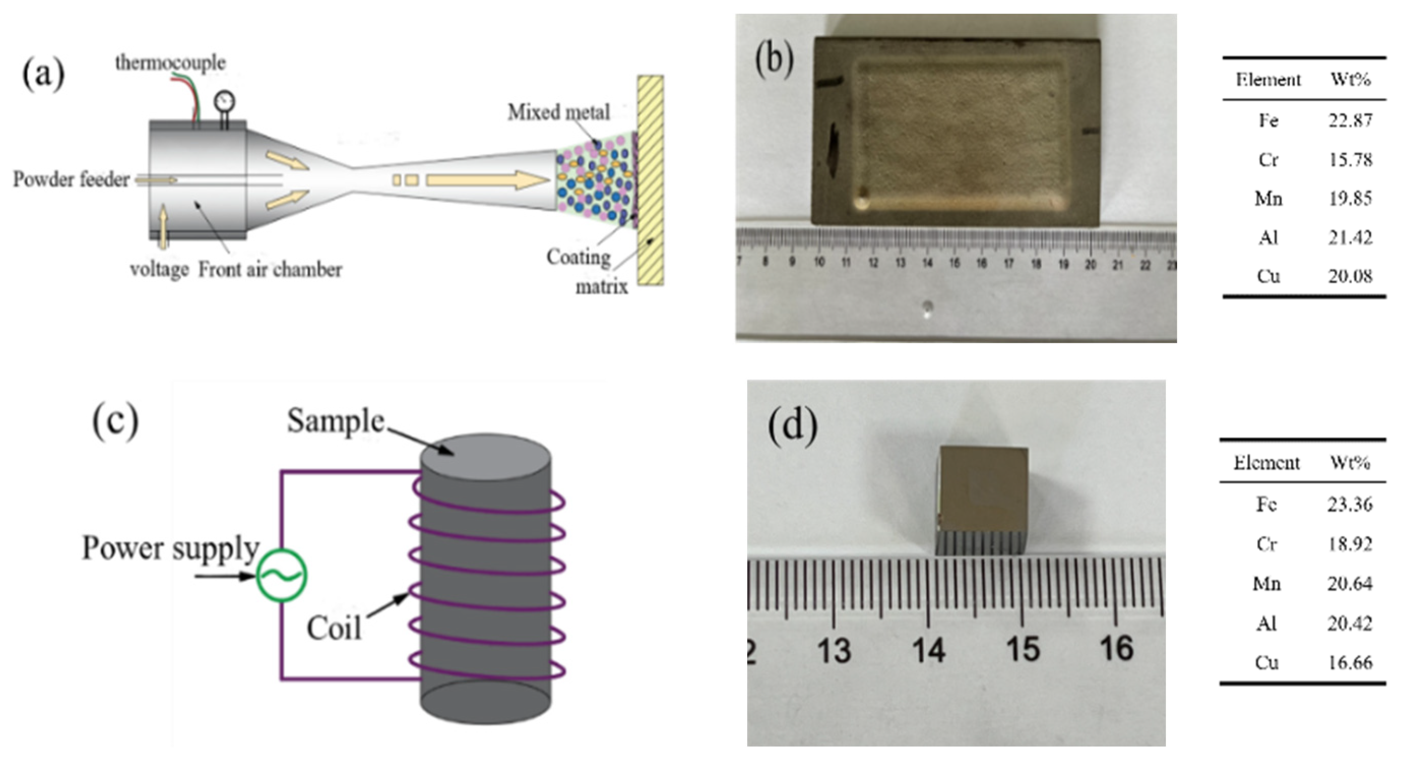
Figure 1. Schematic diagram, macrograph of FeCrMnxAlCu HEA coating synthesized through cold spray-assisted induction remelting. (a) Schematic diagram of cold spray-assisted process; (b) macrograph of cold sprayed mixed metal coating; (c) schematic diagram of induction remelting process; (d) macrograph of induction-remelting coating.
Coatings 13 01401 g001
Figure 2. XRD diffraction patterns and magnified images of the FeCrMnxAlCu HEA and coating: (a) vacuum arc melting alloys; (b) induction remelting coating.
Coatings 13 01401 g002
Figure 3. SEM images of FeCrMnxAlCu HEA prepared through vacuum arc melting. (a) x = 0.5; (b) x = 1; (c) x = 1.5; (d) x = 2.
Coatings 13 01401 g003
Figure 4. Surface images of the FeCrMnxAlCu HEA coating synthesized through induction remelting. (a) x = 0.5; (b) x = 1; (c) x = 1.5; (d) x = 2.
Coatings 13 01401 g004
Figure 5. TEM microstructure and SEAD patterns of the FeCrMnAlCu HEA: (a) bright-field TEM image; (b) SAED along [001] axis of BCC phase; (c) SAED along [−111] axis of FCC phase.
Coatings 13 01401 g005
Figure 6. HRTEM images and FFT patterns of the FeCrMnAlCu HEA: (a) HRTEM image taken from the 001 direction; (b) FFT pattern of B2 particles; (c) FFT pattern of BCC phase matrix.
Coatings 13 01401 g006
Figure 7. TEM microstructure and corresponding selected area electron diffraction patterns of the induction-remelted FeCrMnAlCu HEA coating: (a) high-angle annular dark-field image showing the dual-phase structure of BCC and FCC and (b,c) diffraction patterns of BCC and FCC phases.
Coatings 13 01401 g007
Figure 8. Microhardness and wear rate of FeCrMnxAlCu HEA and coatings fabricated through vacuum arc melting and induction remelting: (a) vacuum arc melting and (b) induction remelting.
Coatings 13 01401 g008
Figure 9. Surface wear images and abrasive SEM images of the induction remelting FeCrMnxAlCu HEA coating: (a,a1) x = 0.5; (b,b1) x = 1; (c,c1) x = 1.5; (d,d1) x = 2.
Coatings 13 01401 g009
Figure 10. FeCrMnAlCu HEA coating EDS diagram.
Coatings 13 01401 g010
Figure 11. The XRD patterns of wear debris from the induction-remelted FeCrMnxAlCu HEA coatings.
Coatings 13 01401 g011
Disclaimer/Publisher’s Note: The statements, opinions and data contained in all publications are solely those of the individual author(s) and contributor(s) and not of MDPI and/or the editor(s). MDPI and/or the editor(s) disclaim responsibility for any injury to people or property resulting from any ideas, methods, instructions or products referred to in the content.