Abstract
This paper focuses on Fe/TaC composite coatings produced on 145Cr6 steel by laser alloying a TaC precoat in paste form. Fe/TaC coatings were produced in two consecutive steps. The first stage was the application of a precoat in paste form made from tantalum carbide and water glass on a steel substrate. Three TaC precoat thicknesses were produced: 30 µm, 60 µm and 90 µm. In the second step, the TaC precoat was remelted on a steel substrate using a 3 kW rated diode laser beam. A constant laser beam scanning speed of 3 m/min and three laser beam powers were used: 500 W, 800 W and 1100 W. In the study, microstructure, microhardness, chemical and phase composition and wear resistance were tested. The aim of the research was to check the possibility of producing composite coatings in which the reinforcing phase will be TaC, and the role of the matrix will be played by the material from the substrate. It was found that it is possible to produce the continuous composite coatings by remelting the TaC precoat with steel substrate. As microhardness increased, so did wear resistance. The coating microhardness obtained ranged from about 750 to 850 HV0.05 depending on the parameters used.
1. Introduction
The construction and tooling materials currently used for specialist products often have a fairly high price. An alternative way to increase their durability is to apply an appropriate surface treatment that will increase hardness and ensure good friction wear resistance in the subsurface zone while maintaining a ductile core. The most commonly used surface treatments are carburizing and nitriding processes. Despite their many advantages, a significant drawback is their high energy intensity. Therefore, special attention should be paid to technologies that use high-energy heat sources such as a laser beam or plasma [1,2,3]. This type of heat source is used in laser [1,2] or plasma remelting [3], laser hardening [1,2], laser alloying [4,5] or laser cladding [6,7,8,9,10,11,12]. These technologies are used to modify tool surfaces or machine parts [1,13]. A laser beam is used on various metal alloys (Fe, Ni, Ti and Al), out of which iron-based alloys are the most common [5,8,9]. Laser processing allows for the modification of selected fragments of the product, often in hard-to-reach places. In addition, these processes can be easily automated, and thus changes in the material can be controlled. A laser beam is successfully used to produce hard carbide-containing coatings on products used in mining and agriculture [8]. Remelting substrate material with carbides produces a composite layer. The most commonly used reinforcing phases are tungsten carbides such as WC and W2C [8,11,12], silicon carbides [6], boron carbides [7], titanium carbides [9] or zirconium carbides [10]. In scientific publications, much less attention is paid to tantalum carbides, which also have many important properties. Tantalum carbide has one of the highest melting points of any known chemical compound. It is used as a material for the production of tools as well as a component of casting molds, where it has a positive effect by reducing friction between meld surfaces and the object cast, and is an important component of cermets. One of the few dated research papers in which the authors studied topics related to the production of the TaC layer was the work of Teghil et al. [14]. The authors used the pulsed laser deposition technique to obtain TaC layers deposited on graphite substrates. Based on the obtained results, they only showed that the laser technique may be suitable for the production of TaC films with noticeable homogeneity and adhesion. There are studies available in which researchers focus on the surface treatment of sintered carbide tools containing carbides WC, TiC and TaC [13,15]. In paper [15], the authors carried out laser heating of the surfaces of sintered carbide tools. They found that Co and TaC melt in the early heating stage due to their relatively lower thermal conductivity than WC. On the other hand, in paper [16] the authors deposited thin layers of Ti, Zr, Hf and Ta carbides on a titanium substrate using the pulsed laser ablation method. The layers obtained were smooth and compact. A majority of available studies focus on the production of a layer containing tantalum carbides by in situ synthesis [17,18,19,20,21,22,23]. In study [17], an in situ synthesized TaC composite coating reinforced with Ni-based solid particles was produced on steel in the process of laser cladding a mixture of Ni60 alloy powder with admixture (Ta2O5 + C). It was shown that the coating is metallurgically bonded to the substrate and has a homogeneous, fine-grained microstructure. Compared to the Ni60 coating, the hardness of the TaC/Ni60 composite coating was increased. In paper [19], the authors aiming to improve the wear resistance of copper strengthened it by adding TaC particles, which were synthesized in situ by laser surface modification with a mixture of NiCrBSi + (Ta2O5 + C) powders. TaC particles synthesized in situ were uniformly dispersed in the solid solution matrix. The modified layer showed higher hardness and better wear resistance. In [20], the authors added tantalum to the laser-clad NiCrBSi coating in order to improve the wear resistance. The in situ synthesized TaC particles of a nearly equiaxed shape were uniformly dispersed in the coating. TaC molecules had good bonding with the matrix and tended to crumble and squeeze into the matrix instead of being pulled out of the wear surface in the abrasion process. NiCrBSi coating with Ta showed higher crack resistance and higher abrasive and adhesive wear resistance than the NiCrBSi coating. In paper [22], the authors produced Ta-reinforced, cobalt-based composite coatings using direct laser deposition technology on the surface of martensitic stainless steel. The results indicate that the in situ synthesized TaC phases can effectively mitigate the impact of particulate matter in the erosion process and improve the erosion resistance of cobalt-based composite coating. The authors in study [23] examined the problem of cracking and the porosity of high-strength composite Ni60A/WC laser clad coatings. The influence of varying contents of Ta powder on phase composition, microstructure, microhardness and friction properties of the Ni60A/WC composite coating was investigated. The Ta powder was added to synthesize TaC in situ with carbon in a melt pool. The results show that Ta combines more easily with carbon. Fine TaC particles synthesized in situ are used as nucleation sites to significantly fragment the grains and improve microstructure homogeneity. As the content of Ta powder increases, the microhardness and wear resistance of the composite coating first increases and then decreases. This finding is closely related to the fragmentation of the microstructure, uniform distribution of the hard phase and dissolution of WC particles. The authors of study [24] investigated the properties of laser-clad nickel-based powders with the addition of TaC nanopowders. They showed that the microhardness of the coating with the addition of tantalum carbide nanopowder differs from the microhardness of the cladding of a standard nickel-based powder. A tendency to increase microhardness along with a reduced concentration of TaC nanoparticles was also shown. In paper [25], the authors produced laser-clad composite coatings deposited on a Ti6Al4V substrate using mixed Ni-based alloy powders with a varying TaC content (0, 5, 10, 15, 20, 30 and 40% by weight). They found that with an increase in TaC content, the coefficient of friction of these coatings showed a decreasing trend due to the formation of Ta2O5. In paper [26], the authors added tantalum during laser cladding of the NiCrBSi coating in order to improve high temperature wear resistance. At 700 °C, the wear of the original NiCrBSi coating is 1.5 times greater than that of the Ta-reinforced coating. This is attributed to the Ni matrix reinforced with Ta, TaC of high hardness and thermal stability. In paper [27], the authors examined composite coatings based on TaC/Stellite X-40 Co produced on a nickel–aluminum bronze substrate by laser surface plating. The microhardness, wear resistance and corrosion resistance of the TaC MMC coatings were significantly improved compared to the substrate.
A review of the literature on the subject clearly indicates that available publications mainly focus on the in situ production of tantalum carbide layers, and the majority of studies focused on the analysis of the impact of tantalum addition on tungsten carbide. In this paper, only tantalum carbide particles without the addition of other particles were used. This study presents a continuation of preliminary studies where in the first stage of the research, mainly microstructure changes in single tracks were analyzed. The purpose of these presented studies is to determine the impact of tantalum carbide on the friction wear resistance of multiple tracks produced in terms of their application.
2. Materials and Methods of Research
2.1. Materials
Fe/TaC composite coatings were produced on 145Cr6 tool steel. The chemical composition of the steel substrate is presented in Table 1 and it is in accordance with the manufacturer’s attestation. Tantalum carbide powder (TaC) with a density of 14.3 g/cm³ was used to make the primer. The morphology of TaC powder particles was observed by scanning electron microscopy (SEM) and is shown in Figure 1. TaC molecules were characterized by an irregular shape and the average particle size (APS) was less than 6 μm. The purity of the TaC powder used in the tests was 99.9%.

Table 1.
Chemical composition of steel used [wt.%].
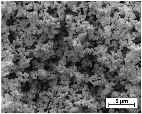
Figure 1.
Morphology of TaC powder particles (SEM image).
2.2. Precoat Production and Laser Processing Parameters
Before testing, the surface of the steel samples was ground to obtain uniform surface roughness. The samples were then purified with alcohol and finally degreased with acetone. In the first step of producing the composite coatings, paste-form TaC precoats were applied to the steel surfaces. This paste consisted of TaC powder as a base material and a solution of sodium water glass with distilled water as a binder. The consistency of the prepared paste was crucial due to the ease and possibility of applying it with a brush. A paste that is too liquid does not allow for the formation of a precoat of a suitable thickness. Too dense paste, on the other hand, does not allow for maintaining a homogeneous thickness. The paste was therefore prepared in such a way that for every 10 g of tantalum carbide, there were 3 mL of water glass and 3 mL of distilled water. Exactly the same proportions were used in the preliminary studies [28]. Precoat thicknesses were measured using the ultrasonic thickness sensor PosiTector® 6000 Advance (DeFelsko Corporation, Ogdensburg, NY, USA) with an accuracy of ±2 μm. Only precoats characterized by the same thickness over the entire surface of the sample were subjected to laser treatment. The second stage was the laser remelting process. A TruDiode 3006 (TRUMPF, Ditzingen, Germany) diode laser with a rated power of 3 kW was used. The laser head was controlled by a 5-axis KR16-2 robotic arm (KUKA, Augsburg, Germany). Three continuous laser beam powers of 500 W, 800 W and 1100 W were used. The laser beam scanning speed was constant during all processes and was 3 m/min. The laser beam diameter was 1 mm while its wavelength was 1040 nm. In contrast to preliminary tests, in which only single tracks were performed, in the tests described in this article we focused on multiple tracks that allow for the production of full-size coatings. This process involved shifting the laser beam from one edge of the sample to the other and turning off the laser. Then, the laser head was returned to the starting point, after which it was moved transversely by 0.5 mm. The laser was turned on and the first move was repeated. This was repeated until the entire surface of the sample was laser remelted. The laser track overlap was 50%. The laser remelting scheme is shown in Figure 2.
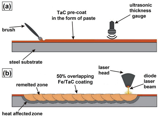
Figure 2.
Scheme of Fe/TaC coatings production using laser remelting: pre-coat preparation (a), laser processing (b).
2.3. Microstructure Investigation
Microstructure observations were made on cross-sections of samples perpendicular to the produced coatings on a scanning electron microscope with the Schottky emission gun (FEG SEM) MIRA3 (TESCAN, Brno, Czech Republic) and Eclipse MA200 light microscope (Nikon, Tokyo, Japan). Cross-sections of steel samples with Fe/TaC composite coatings produced were ground and polished using the Mecatech 250 device from PRESI (Eybens, France). Grinding and polishing discs were used for hard materials in accordance with the manufacturer’s recommendations. In order to reveal the microstructure of the produced coatings, the cross-sections were digested in a 5% solution of HNO3 for 45 s.
2.4. Chemical and Phase Composition Examination
In order to determine the chemical composition of Fe/TaC composite coatings, energy dispersive X-ray spectroscopy (EDS) was used. The Ultim Max 65 spectrometer (Oxford Instruments, High Wycombe, UK) and Aztec Energy Live Standard software (Oxford Instruments, Abingdon, UK) were applied. The results of the study are presented as a map of the chemical elements. During this study, a working distance equal to 15.0 mm with accelerating voltage 10.0 kV was used. Phase composition studies were also carried out using the X-ray diffraction (XRD) method. An EMPYREAN (Malvern PANalytical, Malvern, UK) X-ray diffractometer equipped with a ceramic X-ray tube with a Cu anode was used to identify the phases. In the tests, a voltage of 45 kV and a current of 40 mA were used, and the temperature during the tests was 25 °C. The step size was 0.0330 °2Θ and scan step time was 596,900 s.
2.5. Microhardness Measurements
Microhardness tests of the Fe/TaC coatings were carried out on cross-sections perpendicular to the coating from the surface to the steel core using Future-Tech’s FM-810 (Kawasaki, Japan) microhardness meter equipped with an FT-Zero (Future-Tech, Kawasaki, Japan) automatic measurement program. The Vickers method was used. Each recess was made at a load of 50 g and a loading time of 15 s. The results obtained allowed for the execution of microhardness profiles. The TaC hardness is known (reaching even 2000 HV); therefore, attempts were made to perform hardness measurements not directly in the place of the reinforcing phase but between them—in the matrix.
2.6. Wear Resistance Tests
Wear resistance tests were carried out on an MBT-01 Amsler type (Poznan, Poland) tribometer. The test sample was a steel sample with an Fe/TaC composite coating, while the counter-sample was a ring made of Hardox steel with a hardness of 35 HRC. Dry friction conditions were used with the following parameters: counter-sample rotational speed of 250 rpm, pressure force on the sample of 147N and friction time of 60 min. The weight loss of the sample was checked every 10 min by measuring on the AS220 analytical scale R2 from RADWAG (Poznan, Poland). The aim of abrasion resistance tests was to find a correlation between laser beam power, precoat thickness, microhardness and friction effects on the produced Fe/TaC composite coatings.
3. Results and Discussion
3.1. Macroscopic Observation and Microstructure Analysis
Figure 3 shows macroscopic images of the Fe/TaC coatings produced. It can be seen that track geometry is influenced by both laser beam power and precoat thickness. Increasing the laser beam power from 500 W to 1100 W clearly resulted in the formation of irregular tracks, regardless of the precoat thickness. For example, comparing two Fe/TaC coatings produced using a 30 µm precoat, but one using a 500 W laser beam power (Figure 3a), and the other at 1100 W (Figure 3g), the widening of the tracks of the latter and its irregular shape are clearly visible. A higher laser beam power causes a very large remelting and mixing of the material on the surface. It should be noted, however, that the thicker the precoat, the greater the irregularity. This is related to the consistency of the applied paste and difficulties in its application in thicker precoats.
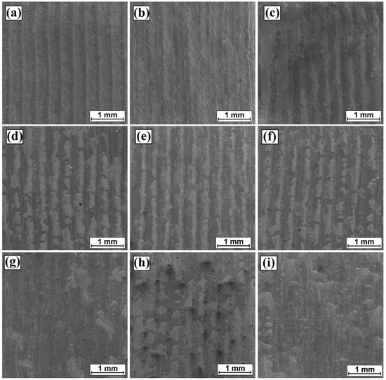
Figure 3.
Macroscopic images of Fe/TaC coatings produced using: (a) 500 W and 30 µm precoat, (b) 500 W and 60 µm precoat, (c) 500 W and 90 µm precoat, (d) 800 W and 30 µm precoat, (e) 800 W and 60 µm precoat, (f) 800 W and 90 µm precoat, (g) 1100 W and 30 µm precoat, (h) 1100 W and 60 µm precoat and (i) 1100 W and 90 µm precoat.
Full-size coatings produced using the parameters developed as part of the preliminary study were described in the work [28]. Figure 4 shows all the coatings along their entire cross-sections. It can be seen that as laser beam power increases, a fairly thick heat-affected zone is produced. Due to the fact that the sample heats up in the process, this zone increases in the direction of coating production. Bright spots on the sample cross-section are the sites of TaC powder agglomerates, which, due to the high melting point, were not remelted by the laser beam. These agglomerates formed mainly when the thickest precoat was produced and are most visible in Figure 4c,i.
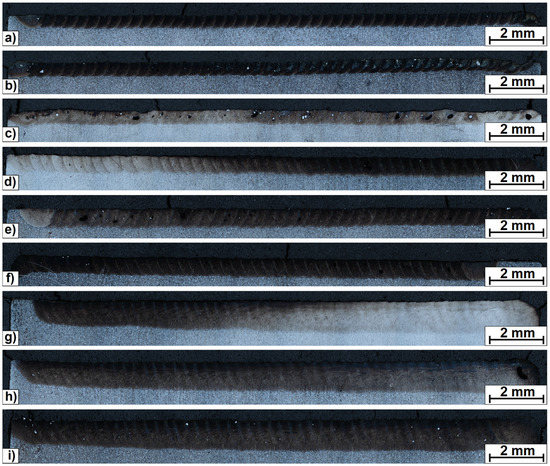
Figure 4.
Cross-section of Fe/TaC coatings produced using: (a) 500 W and 30 µm precoat, (b) 500 W and 60 µm precoat, (c) 500 W and 90 µm precoat, (d) 800 W and 30 µm precoat, (e) 800 W and 60 µm precoat, (f) 800 W and 90 µm precoat, (g) 1100 W and 30 µm precoat, (h) 1100 W and 60 µm precoat and (i) 1100 W and 90 µm precoat.
In order to take a closer look at the microstructure of individual Fe/TaC coatings, images were taken in scanning microscopy (Figure 5, Figure 6 and Figure 7). Figure 5 shows the coatings produced at a laser beam power of 500 W and the thickness of the TaC precoat coating, respectively: 30 µm (Figure 5a,d,g), 60 µm (Figure 5b,e,h) and 90 µm (Figure 5c,f,i). It was found that as the thickness of the TaC precoat increased, the tendency to form TaC powder agglomerates increased. These agglomerates are clearly visible in Figure 5c. An increased number of TaC particles makes it difficult to produce a homogeneous paste. TaC powder particles with a melting point of over 3700 °C melt in the laser processing and by combining bring about agglomerate formation. This is a problem that was partially solved by increasing the laser beam power. An analysis of the microstructure at higher magnification can lead to a conclusion that the coatings are made of matrix (dark area) and carbide mesh (Figure 5d), in which eutectic can be observed (Figure 5g). An increase in the amount of TaC carbides caused by the use of a thicker precoat gradually gives rise to the appearance of only partially remelted (Figure 5h) or unmelted TaC particles (Figure 5f). However, it can be stated that these particles also have the form of two or more tantalum carbide particles joined together (Figure 5i). Such a structure proves the composite nature of some of the produced Fe/TaC coatings.
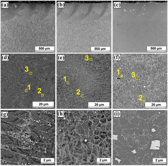
Figure 5.
Microstructure of Fe/TaC coatings produced using: (a,d,g) 500 W and 30 µm precoat, (b,e,h) 500 W and 60 µm precoat and (c,f,i) 500 W and 90 µm precoat.
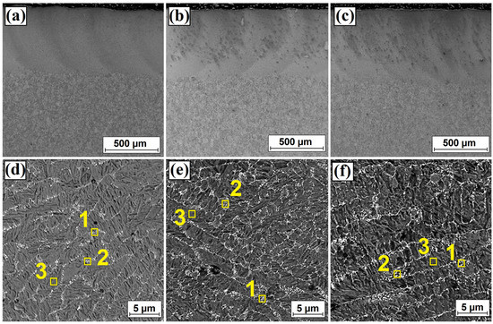
Figure 6.
Microstructure of Fe/TaC coatings produced using: (a,d) 800 W and 30 µm precoat, (b,e) 800 W and 60 µm precoat and (c,f) 800 W and 90 µm precoat.
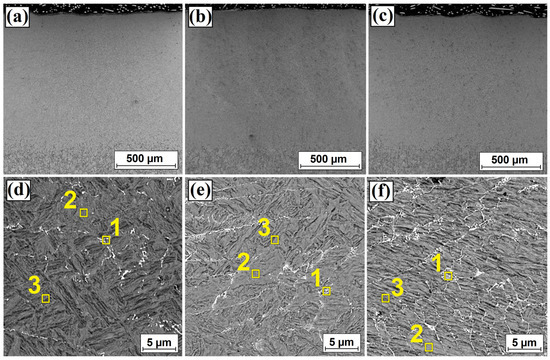
Figure 7.
Microstructure of Fe/TaC coatings produced using: (a,d) 1100 W and 30 µm precoat, (b,e) 1100 W and 60 µm precoat and (c,f) 1100 W and 90 µm precoat.
Figure 6 shows the coatings produced at a laser beam power of 500 W and the thickness of the TaC precoat, respectively, as 30 µm (Figure 6a,d), 60 µm (Figure 6b,e) and 90 µm (Figure 6c,f). An increase in the thickness of the remelted zone was found in comparison to the coatings produced at a laser beam power of 500 W. The increase in the laser beam power resulted in a complete remelting of both TaC particles and possibly agglomerates formed of those particles that may have been present in the precoat. It was found that the most significant change in the microstructure was the increased intensity of the occurrence of the secondary carbide mesh. It can be seen that when using a 30 µm precoat (Figure 6d), white precipitates in mesh form are much fewer than in a coating produced using a precoat with a thickness of 90 µm (Figure 6f). The same relationship can be observed in Figure 7, where the coatings produced at a laser beam power of 1100 W and the thickness of the TaC precoat of 30 µm (Figure 7a,d), 60 µm (Figure 7b,e) and 90 µm (Figure 7c,f) are shown, respectively. An increase in the precoat thickness resulted in an increase in the number of secondary carbide precipitates in mesh form. However, the use of a laser beam power of 1100 W significantly contributed to the overall reduction of the presence of the mesh in the structure. This is due to an increase in the amount of iron in the produced coating which comes from the steel substrate.
3.2. Chemical and Phase Composition Results
The results of the EDS point analysis for the sites marked with yellow squares in Figure 5, Figure 6 and Figure 7 are presented in Table 2. Characteristic areas of the obtained microstructure were analyzed, i.e., light areas in the form of precipitates and mesh, as well as dark areas forming the coating matrix. Three chemical elements were taken into account: tantalum, carbon and iron, all derived from the steel substrate. It can be seen that increased tantalum content occurs in bright areas. Bright sharp precipitates are most likely tantalum carbides, as indicated by their high content at the level of approximately 71 wt.% (point 1 of Figure 5, Table 2). Increased tantalum content was also found in bright areas forming the eutectic. Here, its percentage content is about 20–30 wt.%, depending on the pre-applied paste thickness and laser beam power. It can be clearly seen that with the increase in the thickness of the TiC precoat, the share of tantalum increases both in the precipitates in mesh form and in the matrix of the coating produced. A similar relationship also occurs when the laser beam power is changed. Here, the greater the laser beam power, the lesser the tantalum amount. On the other hand, the iron content increases significantly. An analysis of the effect of laser beam power on the chemical composition of the Fe/TaC coating produced using the thickest TaC precoat showed that tantalum content in the substrate area decreased from 16.7 wt.% at 500 W to 1.9 wt.% at 1100 W. A similar relationship was also observed in paper [23], where the authors analyzed the effect of the amount of Ta introduced on the properties of the Ni60A/WC laser-alloyed composite coatings.
In order to check what kind of phases were present in the produced surface layers, XRD phase composition analysis tests were carried out (Figure 8). The presence of peaks derived from the TaC and Ta2C carbide phases as well as from the TaFe2 and Fe phases was found. The influence of laser beam power on phase composition for the thickest TaC precoat was analyzed. It can be seen that at a laser beam power of 500 W, there were distinct peaks derived from TaC and Ta2C carbides as well as from the tantalum-rich phase TaFe2. An increase in laser beam power caused a decrease in the intensity of the peaks or even their complete disappearance with a simultaneous increase in the intensity of the peak derived from iron.
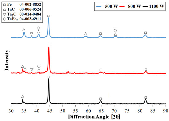
Figure 8.
Phase composition (XRD) of Fe/TaC coatings produced using a 90 µm precoat and different types of laser beam power.
3.3. Microhardness Observations
Figure 9, Figure 10 and Figure 11 show the results of the measurements of the microhardness of tantalum carbide laser-alloyed coatings for the precoat thickness of 30 µm, 60 µm, and 90 µm, respectively. In all the analyzed samples, microhardness gently decreased from the remelted zone enriched in tantalum, through the heat-affected zone, to the substrate, reaching a hardness of approximately 300 HV0.05. Despite the intense movements caused by Marangoni convection forces, the obtained microhardness profiles for the analyzed samples are characterized by a very uniform distribution of microhardness over the entire depth of the remelted zone. A gradual reduction of hardness from the surface towards the substrate of the material is advantageous for potential applications of the coating produced. Figure 9 shows the microhardness profiles for a 30 µm TaC precoat thickness. The highest hardness was obtained by remelting the coating at a laser beam power of 500 W. Here, the hardness in the remelted zone was approximately 750 HV0.05. An increase in laser beam power to 800 W and 1100 W contributed to a reduction in hardness and its value in the remelted zone ranged from 700 HV0.05 to 620 HV0.05. Figure 10 shows the microhardness profiles for a TaC precoat thickness of 60 µm. Here, an increase in hardness for the laser beam powers of 500 W and 800 W by approximately 50–80 units can be seen in comparison to the coating produced at 30 µm. The use of a higher laser beam power does not favorably affect the microhardness. It can be seen, however, that a higher laser beam power results in a lower hardness in the SWC. This is due to the intense heating of one track from the other, and thus slower cooling in this zone. The best results of microhardness measurements were obtained for the precoat thickness of TaC 90 µm (Figure 11). As a result of remelting such a coating thickness with a laser beam power of 500 W, a microhardness of about 850 HV0.05 was obtained. The increase in laser beam power resulted in lower microhardness values at the level of approximately 750 HV0.05 for 800 W and 650 HV0.05 for 1100 W. Analyzing the microhardness graphs, it can be concluded that the use of a low laser beam power and the thickest precoat results in the production of a coating with a favorable hardness. This is also influenced by the rate of heating and cooling, which at a lower power results in a finer microstructure. The authors of paper [27] laser-alloyed a TaC/Stellite X-40 composite coating with nickel–aluminum bronze. Here, the Stellite X40 alloy contained a large amount of Cr element, which also strengthens the solution and contributed to increasing the coating hardness. As in this paper, the authors found that coating hardness increased significantly with an increased TaC content.
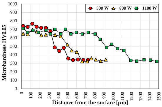
Figure 9.
Microhardness of Fe/TaC coatings produced using a 30 µm precoat and different types of laser beam power.
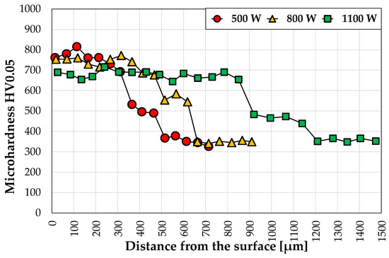
Figure 10.
Microhardness of Fe/TaC coatings produced using a 60 µm precoat and different types of laser beam power.
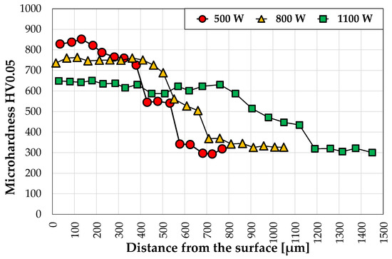
Figure 11.
Microhardness of Fe/TaC coatings produced using a 90 µm precoat and different types of laser beam power.
3.4. Wear Resistance
The produced Fe/TaC composite coatings were subjected to a dry friction wear test. The results of the weight loss measurements of the samples are shown in Figure 12. Figure 12a shows the effect of the thickness of the precoat TaC and the laser beam power of 500 W on the wear resistance of the finally produced Fe/TaC coating. The test results obtained for the coatings were compared with the results obtained for the hardened and tempered steel sample. It can be seen that the production of the Fe/TaC composite coating positively increases the wear resistance of the substrate compared to hardened steel. The greatest resistance to friction wear was found for coatings produced with a TaC precoat thickness of 90 µm. The weight loss of all samples in a time unit is directly proportional. Analyzing the impact of laser beam power at a constant coating thickness of 90 µm, it was found that the best friction wear resistance Is shown by a sample affected by a 500 W laser beam. The use of a higher laser beam power contributed to an increase in weight loss by approximately 3 mg after 60 min in relation to the best coating. Wear resistance is closely correlated to microhardness results—the higher the microhardness, the better the wear resistance. The conducted tests showed that the wear resistance of the Fe/TaC coatings produced is very good compared to the hardened substrate. All produced coatings have about 2.5 times higher wear resistance, which is very important from the application point of view.
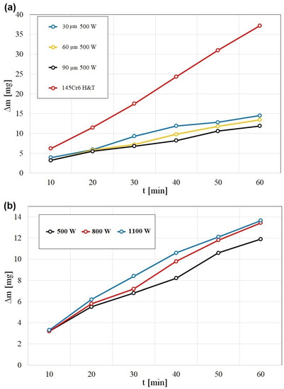
Figure 12.
Wear resistance of Fe/TaC coatings: (a) influence of precoat thickness on wear resistance of coatings produced using 500 W laser beam power and (b) influence of laser beam power on wear resistance of coatings produced using a precoat of 90 µm.
Figure 13, Figure 14 and Figure 15 show sample surfaces following wear resistance tests. Figure 13 shows the surface after a wear test at a constant laser beam power of 500 W and a variable thickness of the TaC precoat. The image in the upper figure shows a view of the wear track with fragments of the laser tracks produced. White areas in the wear track zone are tantalum carbides whose amount is greater with an increase in the thickness of the TaC precoat. The figures beneath show an enlarged fragment from the wear track in SE and BSE contrasts.
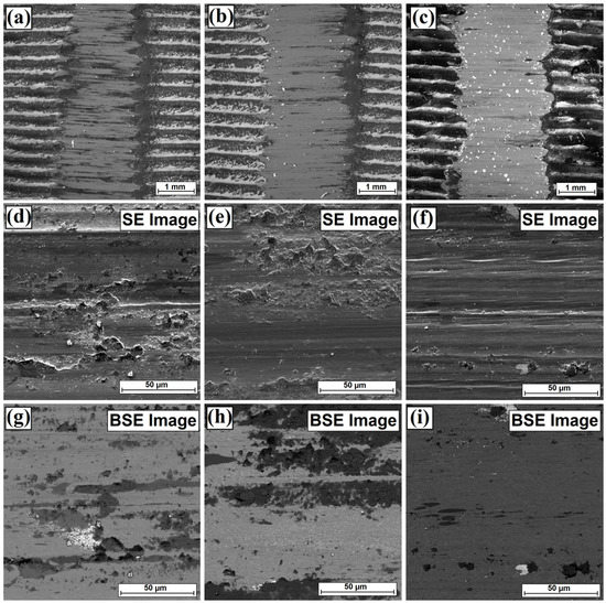
Figure 13.
Surface condition after wear tests of Fe/TaC coatings produced using: (a,d,g) 500 W and 30 µm precoat, (b,e,h) 500 W and 60 µm precoat and (c,f,i) 500 W and 90 µm precoat.
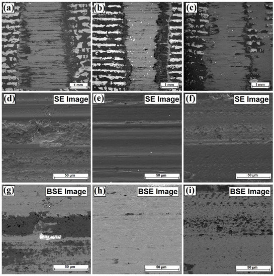
Figure 14.
Surface condition after wear tests of Fe/TaC coatings produced using: (a,d,g) 800 W and 30 µm precoat, (b,e,h) 800 W and 60 µm precoat and (c,f,i) 800 W and 90 µm precoat.
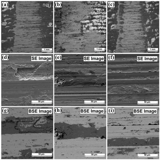
Figure 15.
Surface condition after wear tests of Fe/TaC coatings produced using: (a,d,g) 1100 W and 30 µm precoat, (b,e,h) 1100 W and 60 µm precoat and (c,f,i) 1100 W and 90 µm precoat.
On the surface of the sample, tears from carbide particles are visible. Some carbides that remained in the agglomerates crumble under friction and break away from the produced coating. Such particles then move between the sliding surface causing destruction of the coating and of the counter-sample.
Therefore, the mechanism of abrasion and microflaking can be mentioned here. In addition, a high oxygen content was found in the analyzed samples, which indicates that surface oxidation takes place in the wear process (Figure 16). It can be assumed that in the wear test, the worn surface of the Fe/TaC composite coating is covered with an oxide layer, which may form faster than the resulting wear tracks; hence, there are clearly visible areas in which the tested coating is oxidized. On the basis of the analyzed samples, it can be assumed that one of the leading wear mechanisms of the composite coating is abrasion combined with the oxidation process. Similar relationships were observed by the authors in paper [20], where tantalum was added to the NiCrBSi coating in the laser alloying process. The authors found that the main wear mechanism of the composite coating containing in situ synthesized TaC particles in the dry sliding wear process is abrasion combined with oxidation. In their studies, the authors of paper [20] used 30 N and 75 N loads. Some carbide particles are resistant to pulling out from the matrix in the friction process. Oxides accumulate around them which can protect the coating from direct contact with the counters ample. In the conducted studies, a load of 147 N was applied; therefore, TaC particles may show some tendency to crumble and then squeeze into the matrix instead of pulling out of the wear surface (Figure 13c). Thus, oxide residues and TaC residues inserted into the worn surface will have a positive effect on wear resistance. In all these cases, no cracks are observed at the matrix/reinforcing phase interface. This indicates a reduction in crack initiation and propagation. The structure of the carbide mesh found in Fe/TaC coatings (the thickest precoat) is characterized by good resistance to micro-ploughing, micro-cutting, and thus provides the composite coating with high abrasive and adhesive wear resistance.
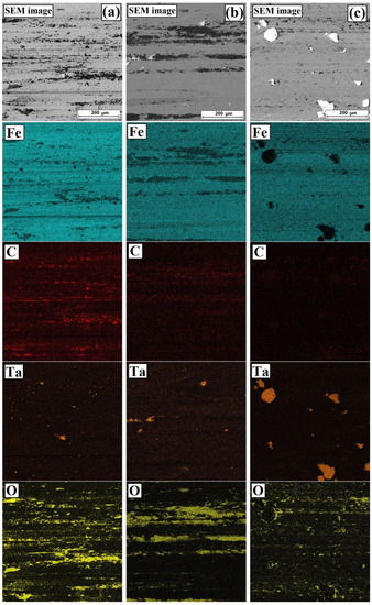
Figure 16.
Surface condition and EDS mapping after wear tests of Fe/TaC coatings produced using: (a) 500 W and 30 µm precoat, (b) 500 W and 60 µm precoat and (c) 500 W and 90 µm precoat.
Figure 14 shows the surface after wear at a constant laser beam power of 800 W and a varying thickness of the TaC precoat. Here, too, a similar mechanism can be observed as for the lower laser beam power. On the surface of the coating grooves are also visible, and the hard reinforcing phase in the form of TaC mesh and carbides occurring in the microstructure makes surface abrasion difficult (clearly visible in Figure 14b). Under the applied load, the large hard phase easily cracks and peels, which leads to the formation of craters (Figure 14a). In the coatings produced at the highest laser beam power (Figure 15), the main wear mechanism was abrasion and adhesion combined with oxidation. Irregular pits prove adhesive wear behavior, while longitudinal grooves indicate the micro-cutting and micro-ploughing effect. The interaction between contacting inequalities of the resulting oxides leads to increased coating wear. It should be noted that the most uniform wear surface track was observed for the Fe/TaC composite coatings produced at the lowest laser beam power. The increase in laser beam power resulted in uneven abrasion of the samples, which can be seen in the wear tracks.
4. Conclusions
Based on the studies carried out for Fe/TaC composite coatings, the following conclusions can be drawn:
- It is possible to produce full-size composite coatings in which the reinforcing phase is TaC and the matrix is iron from the steel substrate.
- An increase in laser beam power reduces the number of TaC particles, simultaneously affecting the composite character of the coatings. In the microstructure, the eutectic of tantalum is formed as a mesh, which creates a reinforcing phase.
- The use of a low laser beam power results in a higher tantalum content in the Fe/TaC coating. On the other hand, an increase in power contributes to the reduction of its share and thus to a reduction in microhardness.
- In terms of wear resistance, it is the most favorable to produce an Fe/TaC coating using a laser beam power of 500 W and a 90 µm precoat.
Author Contributions
Conceptualization, D.B.; investigation, D.B. and A.B.; methodology, D.B. and A.B.; validation, D.B.; visualization, D.B.; writing—original draft, D.B. and A.B.; writing—review and editing, D.B. All authors have read and agreed to the published version of the manuscript.
Funding
The presented research results were funded by grants for education allocated by the Ministry of Science and Higher Education in Poland.
Institutional Review Board Statement
Not applicable.
Informed Consent Statement
Not applicable.
Data Availability Statement
The data presented in this study are available on request from the corresponding author.
Conflicts of Interest
The authors declare no conflict of interest.
References
- Lawrence, J.R.; Waugh, D. Laser surface engineering: Processes and applications. In Woodhead Publishing Series in Metals and Surface Engineering Book, 1st ed.; Kindle Edition: Chester, UK, 2014. [Google Scholar]
- Dowden, J.; Schulz, W. The Theory of Laser Materials Processing: Heat and Mass Transfer in Modern Technology, 2nd ed.; Springer Series in Materials Science; Springer Dordrecht: Bristol, UK, 2017; ISBN-13: 978-3319567105. [Google Scholar]
- Fan, L.I.; Dong, Y.; Chen, H.; Dong, L.; Yin, Y. Wear Properties of Plasma Transferred Arc Fe-based Coatings Reinforced by Spherical WC Particles. J. Wuhan Univ. Technol.-Mater. Sci. Edit. 2019, 34, 433–439. [Google Scholar] [CrossRef]
- Kukliński, M.; Bartkowska, A.; Przestacki, D. Microstructure and selected properties of Monel 400 alloy after laser heat treatment and laser boriding using diode laser. Int. J. Adv. Manuf. Technol. 2018, 98, 3005–3017. [Google Scholar] [CrossRef]
- Dobrzański, L.A.; Labisz, K.; Piec, M.; Klimpel, A. Modelling of surface layer of the 31CrMoV12-18 tool steel using HPDL laser for alloying with TiC powder. J. Achiev. Mater. Manuf. Eng. 2007, 24, 27–34. [Google Scholar]
- Abbas, G.; West, D.R.F. Laser surface cladding of Stellite and Stellite-SiC composite deposits for enhanced hardness and wear. Wear 1991, 143, 353–363. [Google Scholar] [CrossRef]
- Chao, M.-J.; Niu, X.; Yuan, B.; Liang, E.-J.; Wang, D.-S. Preparation and characterization of in situ synthesized B4C particulate reinforced nickel composite coatings by laser cladding. Surf. Coat. Technol. 2006, 201, 1102–1108. [Google Scholar] [CrossRef]
- Bartkowski, D.; Bartkowska, A. Wear resistance in the soil of Stellite-6/WC coatings produced using laser cladding method. Int. J. Refract. Met. Hard Mater. 2017, 64, 20–26. [Google Scholar] [CrossRef]
- Ertugrul, O.; Enrici, T.M.; Paydas, H.; Saggionetto, E.; Boschini, F.; Mertens, A. Laser cladding of TiC reinforced 316L stainless steel composites: Feedstock powder preparation and microstructural evaluation. Powder Technol. 2020, 375, 384–396. [Google Scholar] [CrossRef]
- Lv, X.; Zhan, Z.; Cao, H.; Guo, C. Microstructure and properties of the laser cladded in-situ ZrB2-ZrC/Cu composite coatings on copper substrate. Surf. Coat. Technol. 2020, 396, 125937. [Google Scholar] [CrossRef]
- Bartkowski, D.; Bartkowska, A.; Jurči, P. Laser cladding process of Fe/WC metal matrix composite coatings on low carbon steel using Yb: YAG disk laser. Opt. Laser Technol. 2021, 136, 106784. [Google Scholar] [CrossRef]
- Davoren, B.; Sacks, N.; ·Theron, M. Microstructure characterization of WC-9.2wt%Monel 400 fabricated using laser engineered net shaping. Prog. Addit. Manuf. 2021, 6, 431–443. [Google Scholar] [CrossRef]
- Yilbas, B.S.; Arif, A.F.M.; Karatas, C.; Ahsan, M. Cemented carbide cutting tool: Laser processing and thermal stress analysis. Appl. Surf. Sci. 2007, 253, 5544–5552. [Google Scholar] [CrossRef]
- Teghil, R.; D’Alessio, L.; De Maria, G.; Ferro, D. Pulsed-laser deposition and characterization of TaC films. Appl. Surf. Sci. 1995, 86, 190–195. [Google Scholar] [CrossRef]
- Karatas, C.; Yilbas, B.S.; Aleem, A.; Ahsan, M. Laser treatment of cemented carbide cutting tool. J. Mater. Process. Technol. 2007, 183, 234–240. [Google Scholar] [CrossRef]
- Ferro, D.; Rau, J.V.; Rossi Albertini, V.; Generosi, A.; Teghil, R.; Barinov, S.M. Pulsed laser deposited hard TiC, ZrC, HfC and TaC films on titanium: Hardness and an energy-dispersive X-ray diffraction study. Surf. Coat. Technol. 2008, 202, 1455–1461. [Google Scholar] [CrossRef]
- Chao, M.; Wang, W.; Liang, E.; Ouyang, D. Microstructure and wear resistance of TaC reinforced Ni-based coating by laser cladding. Surf. Coat. Technol. 2008, 202, 1918–1922. [Google Scholar] [CrossRef]
- Yu, T.; Deng, Q.; Dong, G.; Yang, J. Effects of Ta on microstructure and microhardness of Ni based laser clad coating. Appl. Surf. Sci. 2011, 257, 5098–5103. [Google Scholar] [CrossRef]
- Li, M.Y.; Chao, M.J.; Liang, E.J.; Li, D.C.; Yu, J.M.; Zhang, J.J. Laser synthesised TaC for improving copper tribological property. Surf. Eng. 2013, 29, 616–6219. [Google Scholar] [CrossRef]
- Yu, T.; Deng, Q.L.; Zheng, J.F.; Dong, G.; Yang, J.G. Microstructure and wear behaviour of laser clad NiCrBSi+Ta composite coating. Surf. Eng. 2012, 28, 357–363. [Google Scholar] [CrossRef]
- Hu, D.; Liu, Y.; Chen, H.; Wang, M.; Liu, J. Microstructure and properties of in-situ synthesized Ni3Ta-TaC reinforced Ni-based coatings by laser cladding. Surf. Coat. Technol. 2021, 405, 126599. [Google Scholar] [CrossRef]
- Liu, Y.; Ding, T.; Lv, H.; Hu, D.; Zhang, Y.; Chen, H.; Chen, Y.; She, J. Microstructure and properties of Ta-reinforced cobalt based composite coatings processed by direct laser deposition. Surf. Coat. Technol. 2022, 447, 128874. [Google Scholar] [CrossRef]
- Huang, X.; Yu, J.; Jiang, J.; Lian, G.; Chen, C.; Zhou, M.; Xu, W.; Hu, X. Effect of Ta Content on the Microstructure and Properties of Laser Cladding Ni60A/WC Composite Coatings. JOM 2023, 75, 97–108. [Google Scholar] [CrossRef]
- Murzakov, M.A.; Petrovskiy, V.N.; Polski, V.I.; Mironov, V.D.; Prokopova, N.M.; Tret’yakov, E.V. Influence of additions of nanoparticles TaC on a microstructure laser cladding. J. Phys. Conf. Ser. 2015, 594, 012032. [Google Scholar] [CrossRef]
- Lv, Y.H.; Li, J.; Tao, Y.F.; Hu, L.F. High-temperature wear and oxidation behaviors of TiNi/Ti2Ni matrix composite coatings with TaC addition prepared on Ti6Al4V by laser cladding. Appl. Surf. Sci. 2017, 402, 478–494. [Google Scholar] [CrossRef]
- Yu, T.; Chen, J.; Wen, J.; Deng, Q. High temperature phase stability and wear behavior of laser clad Ta reinforced NiCrBSi coating. Appl. Surf. Sci. 2021, 547, 149171. [Google Scholar] [CrossRef]
- Li, Z.; Yan, H.; Zhang, P.; Guo, J.; Yu, Z.; Ringsberg, J.W. Improving surface resistance to wear and corrosion of nickel-aluminum bronze by laser-clad TaC/Co-based alloy composite coatings. Surf. Coat. Technol. 2021, 405, 126592. [Google Scholar] [CrossRef]
- Bartkowski, D. Manufacturing Technology and Properties of Fe/TaC Metal Matrix Composite Coatings Produced on Medium Carbon Steel Using Laser Processing—Preliminary Study on the Single Laser Tracks. Materials 2021, 14, 5367. [Google Scholar] [CrossRef]


Disclaimer/Publisher’s Note: The statements, opinions and data contained in all publications are solely those of the individual author(s) and contributor(s) and not of MDPI and/or the editor(s). MDPI and/or the editor(s) disclaim responsibility for any injury to people or property resulting from any ideas, methods, instructions or products referred to in the content. |
© 2023 by the authors. Licensee MDPI, Basel, Switzerland. This article is an open access article distributed under the terms and conditions of the Creative Commons Attribution (CC BY) license (https://creativecommons.org/licenses/by/4.0/).