Article

Variable Velocity Coating Thickness Distribution Model for Super-Large Planar Robot Spraying

1
School of Mechanical Engineering, Jiangsu University of Science and Technology, Zhenjiang 212000, China
2
Marine Equipment and Technology Institute, Jiangsu University of Science and Technology, Zhenjiang 212003, China
3
School of Naval Architecture and Ocean Engineering, Jiangsu University of Science and Technology, Zhenjiang 212000, China
4
School of Automation, Jiangsu University of Science and Technology, Zhenjiang 212000, China
*
Author to whom correspondence should be addressed.
Coatings 2023, 13(8), 1434; https://doi.org/10.3390/coatings13081434
Submission received: 28 June 2023 / Revised: 20 July 2023 / Accepted: 8 August 2023 / Published: 15 August 2023

Abstract

:
This study proposed a dynamic optimization method for spray gun flow to address the issue of uneven film thickness in the acceleration and deceleration section of the z-shaped spray trajectory in large plane ship segments. The method takes into account the acceleration and deceleration section of the spray trajectory and improves the film thickness distribution. The study first established a static vertical spray coating growth model of the spray gun without considering the acceleration and deceleration of the spray trajectory. Then, we used an integral method to optimize the coating uniformity and established a film thickness distribution model. The optimization of spray speed and spray spacing is crucial in the use of variable flow spray guns. It is assumed that the acceleration and deceleration sections of the spraying trajectory are linear and symmetrical, which forms the basis for establishing a mathematical model for the variable flow spray gun. To determine the flow of the spray gun at different speeds in the acceleration and deceleration sections, the pattern search method was adopted. A section of a ship was used as an example for this study. In this study, we utilized numerical simulations to compare the uniformity of paint film thickness when using a spray gun with a constant flow versus variable flow. The results indicate that when taking into account the acceleration and deceleration section of the spray trajectory, the film thickness was more uniform with a variable flow. These findings demonstrate the feasibility and effectiveness of the proposed method.

1. Introduction

Spraying robots are advanced automatic spraying equipment widely used in the automobile industry and other fields using spraying operations [1,2,3,4]. However, they are rarely used in ship segment spraying due to the large size of ship segments, the different structures, and the typically single-piece spraying process. Consequently, the spraying of large ship segments is mainly carried out manually, which has disadvantages such as low work efficiency, uneven film thickness, and high labor intensity for spraying workers. In recent years, there has been an increasing focus among scholars on utilizing spraying robots in the shipbuilding industry to mitigate these issues.
Currently, there are two common methods of trajectory programming for spraying robots: manual instruction programming and offline programming. Manual teaching programming relies on the work experience of teaching workers to teach the spraying track, which has several issues such as low work efficiency and long teaching cycles [5,6,7]. As a result, offline programming has gradually replaced manual instruction programming. Additionally, the parameter optimization of spraying trajectory has become a hot topic among many scholars.
Zeng Yong et al. optimized the spraying angle in order to improve the uneven film thickness after spraying with irregular plane boundaries [8]. Shumei Ma et al. improved the uneven thickness of paint films on ship surfaces by optimizing the spray rate, spray height, and trajectory spacing [9]. Wang Yi et al. focused on the problem of uneven coating thickness in the interface area when air spray guns are used on large plane surfaces. The horizontal lap ratio of the interface area was optimized to improve the uniformity of the film thickness in the interface area [10]. Lin Mengyuan et al. aimed to solve the problem of low spraying quality in the process of trajectory planning of spraying robots. The objective function was the variance between the theoretical value and the actual value of paint film thickness. The corresponding parameters were optimized to improve the quality of spraying [11]. Liu Xuemei et al. optimized the spraying trajectory of a plane by solving the optimal spraying lap rate for the automatic spraying operations for the outer plate surface of large ships [12].
The current focus of research among scholars is the spraying model of spray guns and optimizing the trajectory parameters under a uniform spraying speed. However, recent studies have shown that the spraying speed has the greatest impact on film thickness [13]. During actual spraying, there are acceleration and deceleration sections at the beginning and end of the path, resulting in a significant difference in film thickness uniformity between these sections and the uniform section. This greatly affects the overall spraying quality [14]. For ships, an uneven film thickness will not only lead to appearance problems, but it can also cause regional corrosion and poor protection performance, thus lead to a series of security problems. The main goal of this study was to achieve a uniform film thickness through dynamic spraying speed.
Firstly, the static vertical spray coating growth model of a spray gun was established without considering the acceleration and deceleration of the spray trajectory. Then, an integral method was used to establish a film thickness distribution model for dynamic spraying along a linear trajectory, with the goal of optimizing coating uniformity. The study determined the spraying speed and spacing required to meet these requirements. Next, the film thickness of the acceleration and deceleration sections of the spraying trajectory was optimized, using the initial conditions as parameters. The acceleration and deceleration sections were assumed to be linear and symmetrical, with equal acceleration and deceleration, and a mathematical model of a variable flow spraying gun was established.

2. Description and Analysis of Problem

2.1. Selection of Spray Path in Subsection of Large Plane

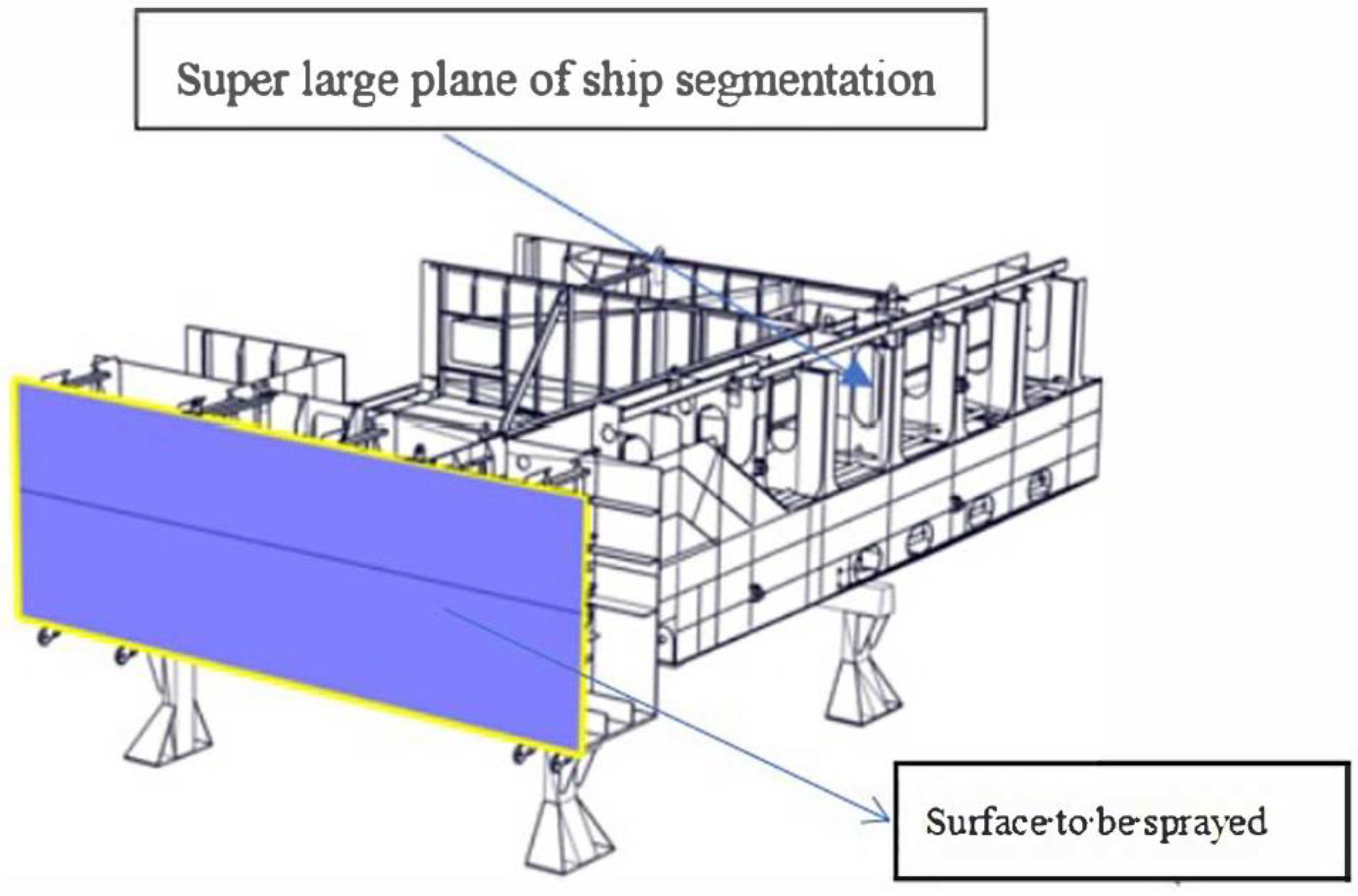
The use of z-shaped and spiral spray tracks for spraying large flat surfaces of ship segments is common nowadays, as demonstrated in Figure 1 [15]. In Figure 2, the appropriate spray trajectory for the large plane of a ship segment is analyzed and selected as an example. Since the standard film thickness is 50 µm, the static vertical spraying coating growth model established in this experiment can ignore the influence of the change in coating thickness caused by gravity. The elliptical double-β model was used in this experiment to calculate any point in the ellipse first, and then calculate the passing time. The integral rule is that the film thickness at this point is an integral function, and the time is the object to be integrated. Thus, the spray film thickness of the trajectory dynamic was obtained.
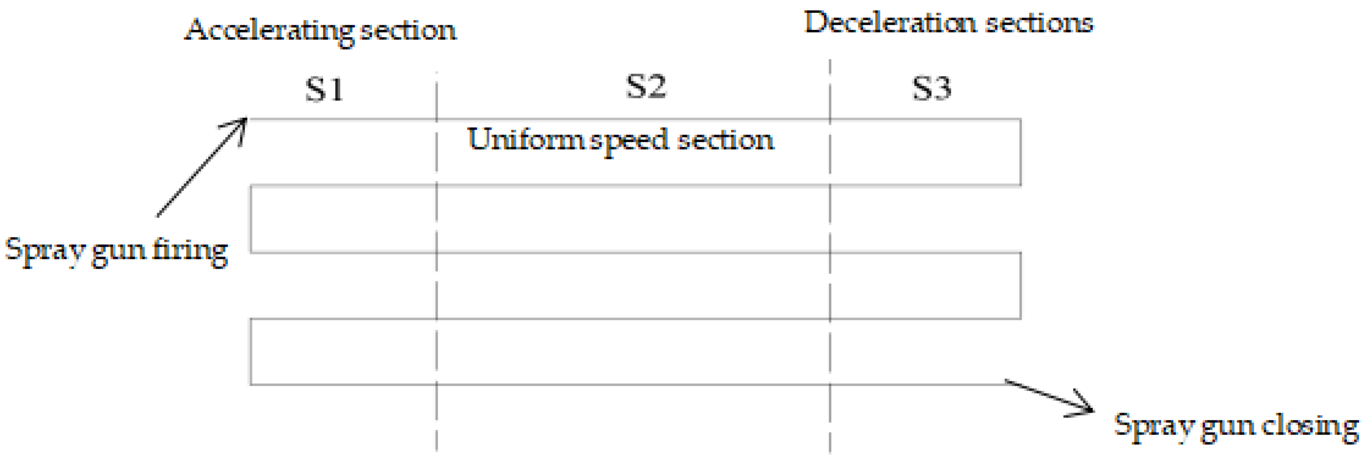
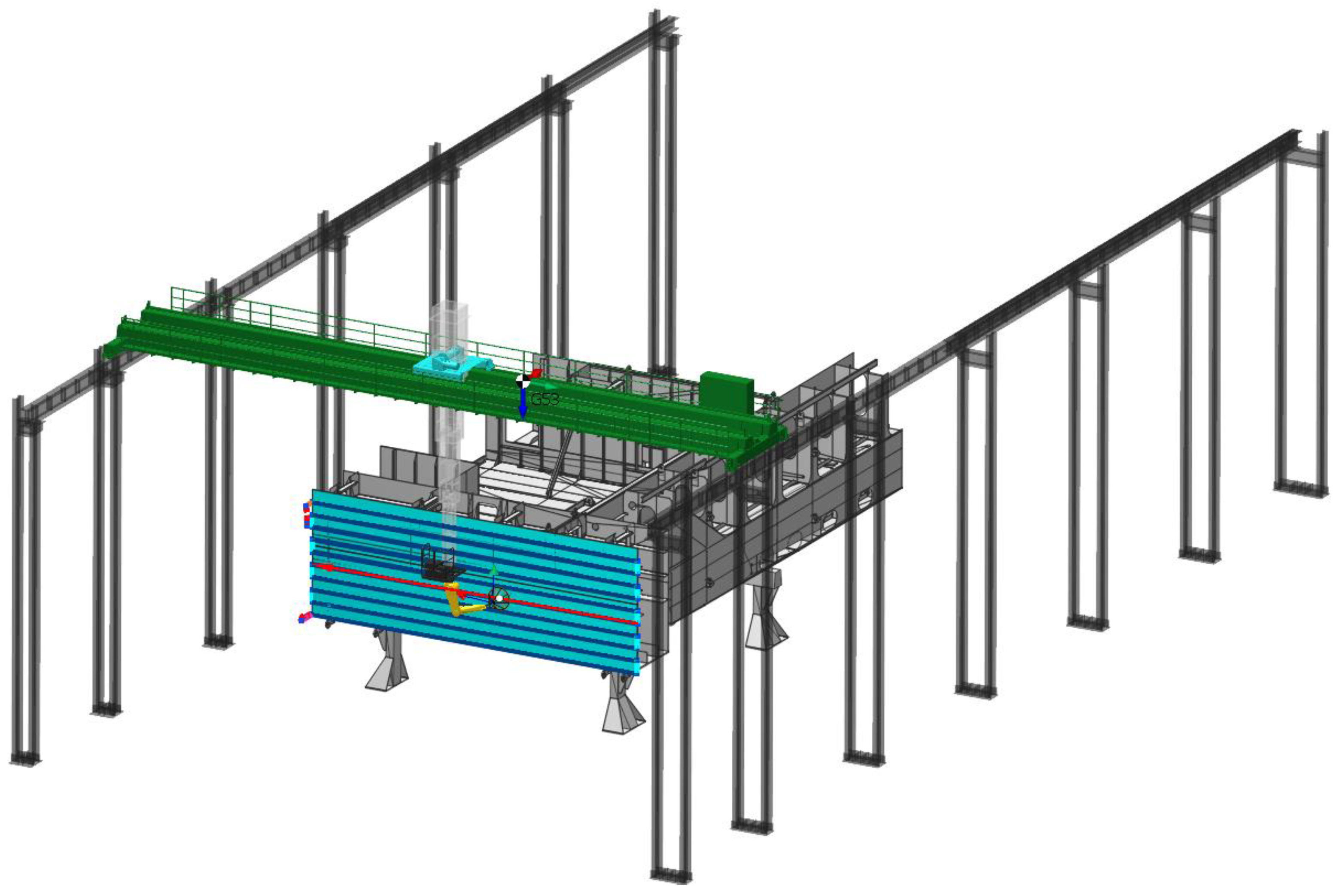
According to Figure 2, the z-shaped spray trajectory is more suitable research on the spray trajectory of large flat surfaces on ship segments. This is because the lap spraying time of adjacent trajectories is less than that of a spiral trajectory, reducing the adverse effects of layering on the spray track. Additionally, the acceleration and deceleration section of the spiral trajectory is greater than that of the z-shaped trajectory, resulting in a less uniform paint film thickness on the large plane of the ship segment. The premise of response surface optimization is that the experimental points should include the best experimental conditions. If the experimental points are not selected properly, the response surface optimization method may not yield good optimization results. Therefore, it is important to establish the factors and levels of reasonable experiments before using the response surface optimization method. Moreover, the large size and inertia of our equipment may impact the spraying efficiency if the Taguchi method is adopted. Therefore, this paper utilized the z-shaped spray track for spraying large flat surfaces on a ship segment.

2.2. The Consequences of Planning Spraying Speed without Considering Acceleration and Deceleration

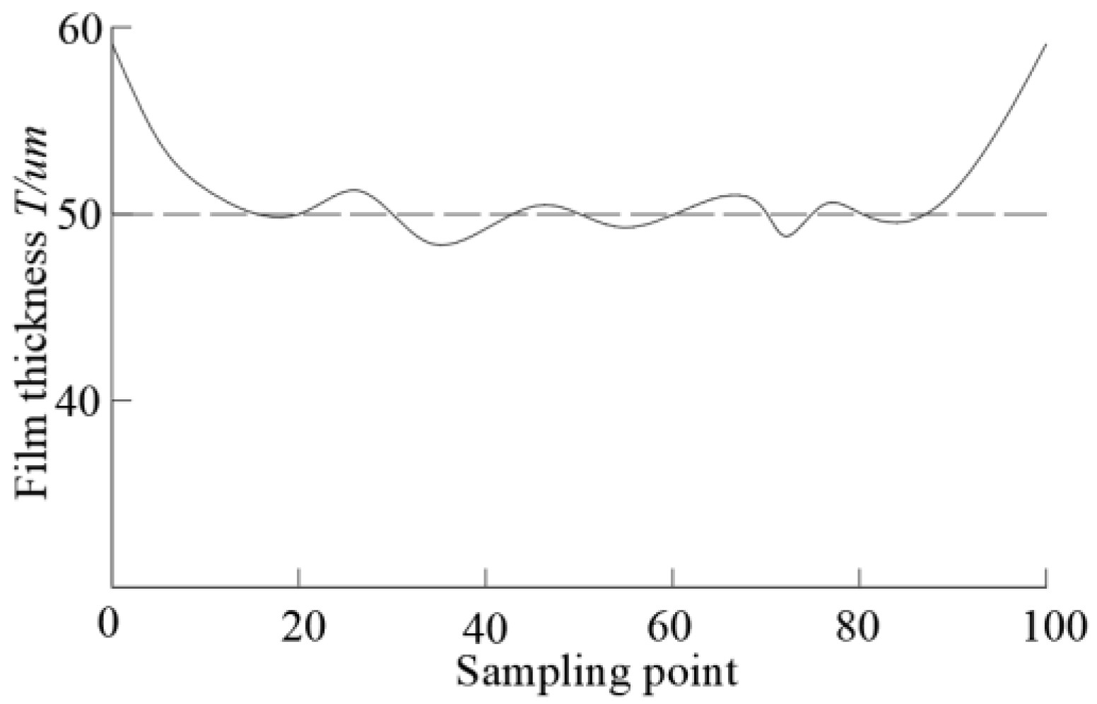
To ensure an even coating thickness in large-plane spraying, scholars have established parameters such as optimal spraying speed, trajectory spacing, and dip angle. These parameters are optimized to achieve a uniform coating thickness. However, the acceleration and deceleration sections of spraying equipment at the beginning and end of the trajectory are often overlooked in the actual spraying process. Figure 3 shows the acceleration and deceleration sections, S1 and S3, respectively, and the uniform speed section, S2, for the z-shaped spraying trajectory. If the original optimized parameters are used for spraying, the uniformity effect of the paint film thickness at the beginning and end of the trajectory will decrease significantly, as depicted in Figure 4. The solid line represents the actual coating film thickness while the dashed line represents the ideal coating film thickness. The figure illustrates a significant increase in coating thickness at the beginning and end of the spraying track, resulting in a decrease in the uniformity of the coating film thickness. To improve the overall film thickness uniformity, it is important to consider optimizing the parameters of the first and last acceleration and deceleration sections of the spraying trajectory during the actual spraying process.

3. Establishment of Mathematical Model

3.1. Static Spraying Model

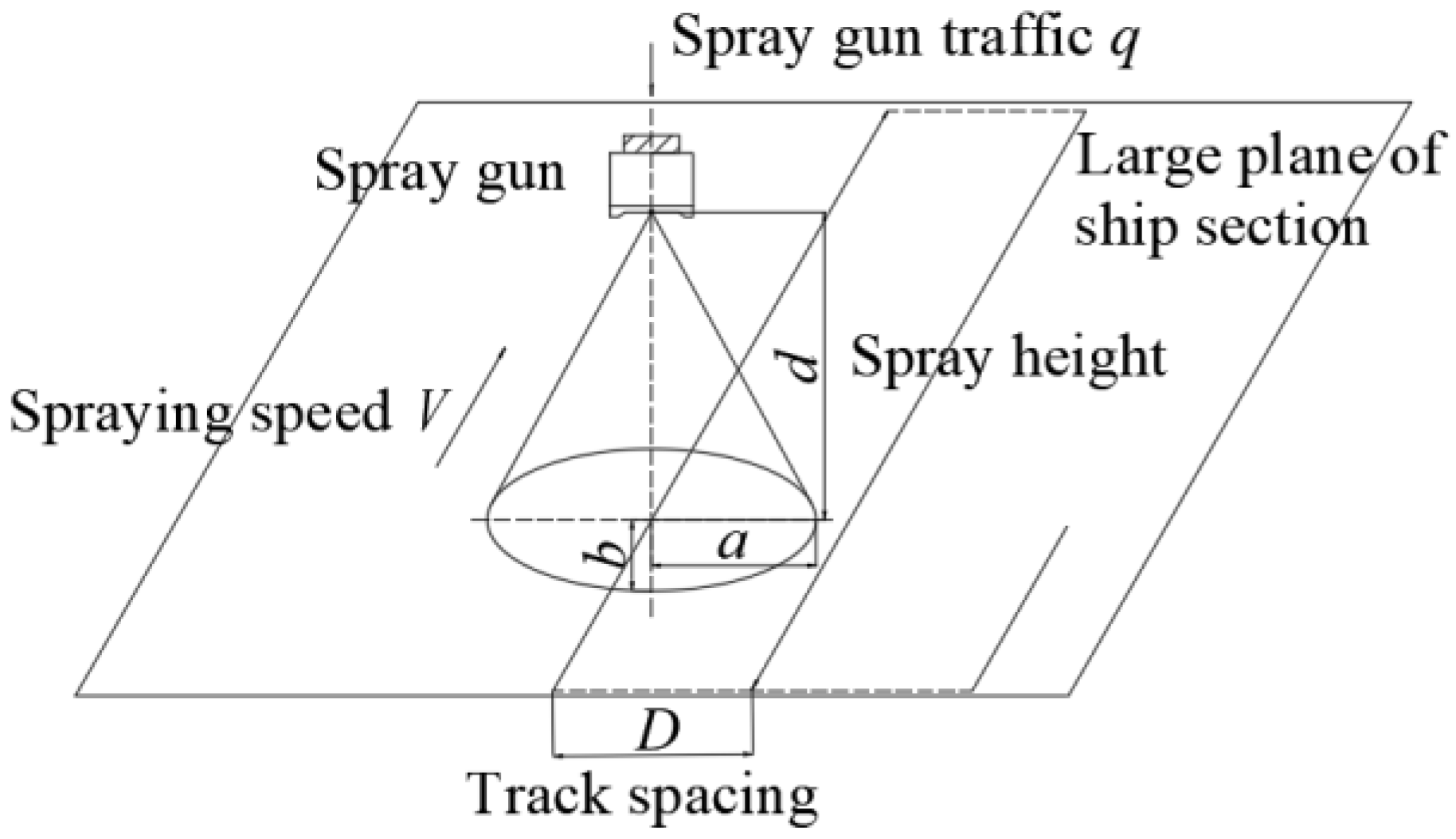
To better understand the spray robot spray gun in relation to the ship segment using the large plane spray mode, we simplified the static spraying process of the spray gun on the large plane of the ship segment, as shown in Figure 5.
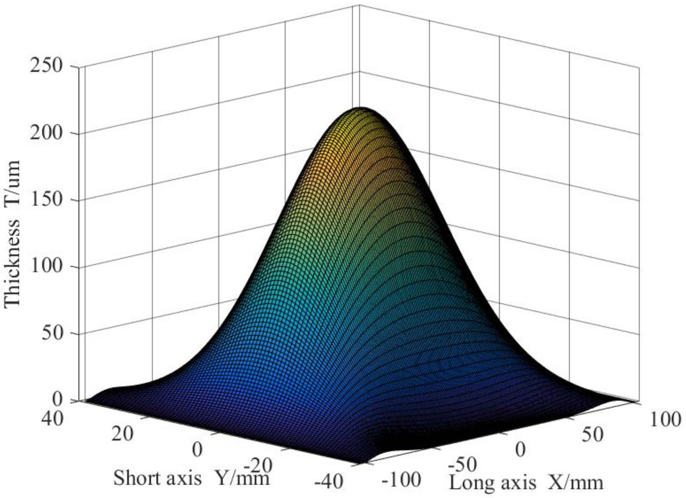
This paper will briefly mention the mature static vertical coating growth rate model. The model used for the growth rate of static vertical spraying coating with a spray gun is the elliptic β model [16]. The spray area formed by the spray gun on a large plane is a standard ellipse. The growth rates of the coating along the long and short axes of the ellipse follow the β distribution, as shown in Figure 6. The thickness of any point in the elliptic region can be expressed as:
T x , y = t m a x 1 x 2 / a 2 β 1 1 1 y 2 b 2 1 x 2 / a 2 β 2 1        
a x a b 1 x / a 2 y b 1 x / a 2
  t m a x is the is the maximum growth rate in the elliptic region. a is the length of the ellipse long half axis. b is the length of the ellipse short half axis. β 1 and β 2 are the β distribution coefficients of the short and long axes, respectively.
To simplify the calculation, take β 1 = β 2 = 2, then
                                                  T x , y = t m a x 1 x 2 / a 2 1 y 2 b 2 1 x 2 / a 2
when the spray gun is sprayed uniformly in a straight line [17].
t m a x = K q 1 / 3 d 3
where K is the growth rate coefficient; q is the flow rate of the spray gun during spraying; and d is the vertical distance between the spray gun nozzle and spraying surface.

3.2. Establishment of Dynamic Model of Spray Gun

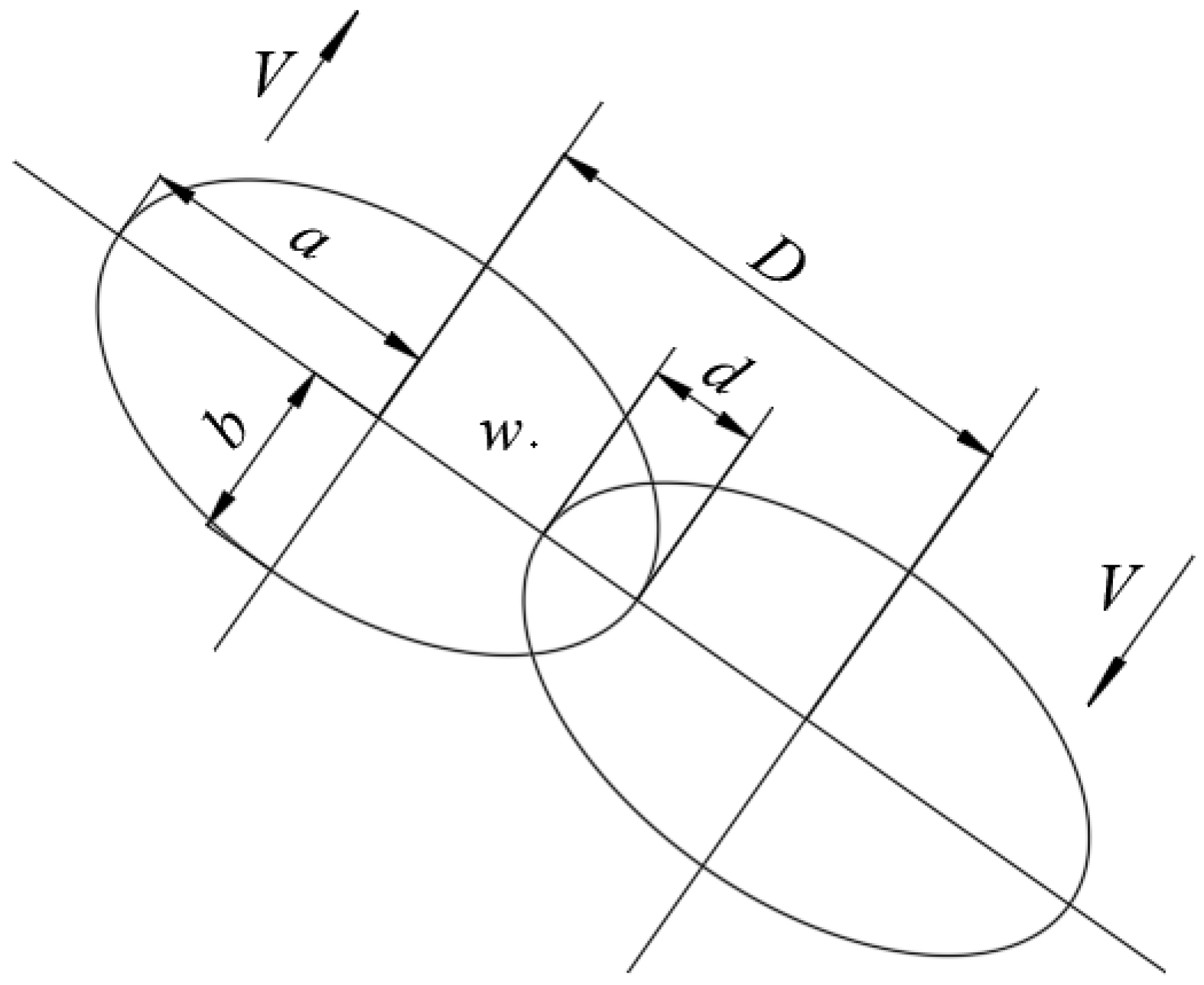
In the context of spray gun usage, W x , y represents the thickness covered by any point w that falls within the spray range when the gun is uniformly sprayed along a straight line. V denotes the dynamic speed of the spray gun when moving along a linear path track, while t represents the time taken to complete the scanning process. w refers to the projection of point w onto a single trajectory, and x represents the distance projected on the X-axis from the point w to w to the prime. Additionally, a and b represent the long and short half-axes of the torch, respectively. The schematic diagram is shown in Figure 7.
The distance traveled at any point is L.
L = 2 b 1 x / a 2
At a spraying speed of V, t is the time taken at any point.
  t = L V
Therefore, the paint film thickness of the spray gun dynamically sprayed along the straight track can be expressed as:
W x , y = 0 t T x , y d t

3.3. Optimization of Track Spacing and Spraying Speed of Paint Film Uniformity under Adjacent Spraying Tracks

Figure 1a shows the spray track on the large flat surface of a ship segment. The growth rate of the film thickness follows the β distribution in the elliptic double beta model, resulting in a thicker coating in the middle and a thinner one on the sides. To ensure uniformity in coating film thickness, the process of spraying should consider the distance between two adjacent tracks, D. The oval torch of the spray gun should be superimposed at a certain distance d in the long half axis direction. By optimizing the appropriate spraying speed V, the desired uniformity requirements for film thickness can be met. Figure 8 illustrates the superposition diagram of two oval torches with adjacent spray tracks.
D = 2 a d  
In the case of uniform linear spraying, the coating thickness in the y direction can be regarded as the same, so y = 0 is substituted into Equation (6). The paint film thickness of the spray gun dynamically sprayed along the linear trajectory can be expressed as:
    W x = 0 t T x d t  
Then, the thickness of point W is:
                      W S x = W s 1 x W s 1 x + W s 2 x W s 2 x 0 x a d a d < x a , a < x 2 a d
where W s 1 x and W s 2 x represent the coating thickness swept by point W spraying on adjacent tracks. The formulas of W s 1 x and W s 2 x are:
W s 1 x = 0 t 1 T x 1 d t ,   0 x a
W s 2 x = 0 t 2 T x 2 d t ,   a d x 2 a d
Among them:
t 1 = 2 b 1 x / a 2 V t 2 = 2 b 1 x 2 a + d 2 a 2 V x 1 = V t 2 + x 2 x 2 = V t 2 + 2 a d x 2
t 1 and t 2 are the spraying times of the spray gun at point W on the adjacent spraying paths. x 1 and x 2 are the distances from the spraying point W to the center points of the adjacent spraying tracks. t is the time taken by points O to W to project onto the spraying trajectory.
Through Formulas (9)–(11), we can get W S x , d , V = 1 V F x , d , in which F is a function of x and d . In order to make the paint film thickness of a ship segment large plane as uniform as possible, we take the variance between the actual and ideal coating thickness of point W as the objective optimization function:
M i n E d , V = 0 2 a d W L W S x , d , V 2 d x
s . t . d 0 , a V 0 ,   600   m m / s
The ideal coating thickness W L can be determined by solving for d and V using the golden section method. This method takes into account certain conditions for the z-shaped spray trajectory, including acceleration and deceleration at the end. The goal is to optimize the uniformity of the film coating thickness in the head and end intervals, ensuring that the coating thickness of the entire plane meets the required specifications and is as uniform as possible.

3.4. Variable Flow Optimization of Spray Gun in the Acceleration and Deceleration Interval at the Beginning and End of Z-Shaped Spraying Trajectory

The track spacing and spraying speed model of paint film uniformity using adjacent spraying tracks were established in Section 3.3. It optimized the spacing of the spray trajectory and the spray speed. The optimum coating thickness can be achieved without considering acceleration and deceleration. In other words, the S2 region has met the requirement of film thickness uniformity when considering acceleration and deceleration.
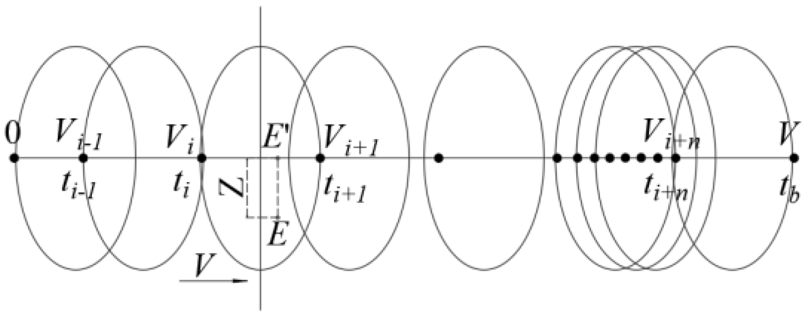
In this section, we will examine the acceleration and deceleration phases at the beginning and end of the z-shaped spray trajectory, as outlined in Section 3.3. We assume that the velocity curve of a single track of the z-shaped spray track is as illustrated in Figure 9. The time–velocity relationship is a uniformly accelerated linear motion in the 0–t1 segment, followed by a uniform linear motion in the t1–t2 segment, and a linear motion with uniform deceleration in the t2–t3 segment. These two forms of motion are symmetric, with only the direction of acceleration being different. Thus, we focused on the uniform acceleration section for our analysis. The uniform velocity in section t1–t2 is the velocity V calculated in Section 3.3, and the acceleration is represented by α . The speed V from zero to uniform spraying time is denoted by t b .
Substituting Formulas (3)–(5) into Formula (8), we can obtain:
W x = K q 1 / 3 d 3 0 2 b 1 x / a 2 V 1 x 2 / a 2 d t
After integration, the paint film coating thickness distribution under uniform motion can be obtained as follows:
W x = 4 b 3 V K q 1 / 3 d 3 1 x 2 a 2 3 2
It can be known from Formula (14) that when the spray gun flow q , spray gun to the large plane of the vertical distance d , oval torch long half axis a , and short half axis b remain unchanged, the rate of spraying is inversely proportional to the thickness of the coating section.
From the property of uniformly accelerated linear motion, the displacement distance in t b time is:
S = 1 2 α t b 2
where S is the distance moved in t b time.
At any time, the speed in the period 0–t1 is:
V n = V t 1 t n
where t 1 = t b , t n is the time at any point in the period 0–t1, and V n is the speed at any point in time.
Figure 10 shows the velocity corresponding to the position of the torch at any time in the uniform acceleration stage. Thus, the film thickness at any point E in the uniform acceleration phase can be found. By using Formula (14), the relationship between spraying speed and flow rate can be established, enabling control of the film thickness at any point in the uniform acceleration phase. Adjusting the flow rate of the spray gun can alter the coating film thickness to meet requirements in this stage. Therefore, at any speed, the formula of spray gun flow is:
W E x = t i t i + 1 4 b 3 V i K q i 1 3 d 3 1 x 2 a 2 3 2 W Y 2 d t
s . t .   q 0 ,   5.5   L / m i n
where W Y is the coating thickness of the sprayed film at any point E when sprayed at uniform speed. q i is the spray flow rate corresponding to a speed of V i . In this paper, the pattern search method was used to solve the constrained optimization problem. The algorithm steps are as follows:
Step 1: A given initial point x 1 = 0 , , 0 T , Direction of n coordinates e 1 ~ e n , The initial step size is λ = 1, reduction rate τ = 0.25, The acceleration factor ρ = 0.5, Allowable error ε = 0.2, the y 1 = x 1 ,   k = 1 ,   j = 1 ;
Step 2: If E y j + λ e j < E y j , then y j + 1 = y j + λ e j , proceed to step 4; Otherwise, go to Step 3.
Step 3: If E y j λ e j < E y j , then y j + 1 = y j λ e j , proceed to step 4; Otherwise y j + 1 = y j λ e j , go to Step 4;
Step 4: If j < n , j = j + 1 , go to Step 2, otherwise, go to Step 5;
Step 5: If E y n + 1 < E x k , go to Step 6; otherwise, go to Step 7;
Step 6: Set x k + 1 = y n + 1 , the y 1 = x k + 1 + ρ x k + 1 x k , k = k + 1 , j = 1 , turn to step 2;
Step 7: If λ ε , stop the iteration and get x k ; Otherwise, λ = τ λ , y 1 = x k , x k + 1 = x k , k = k + 1 , turn to step 2.
The pattern search method is an optimization algorithm that is used to find the best solution or approximate optimal solution in a given search space. It gradually approaches the optimal solution by moving through the search space and adjusting and optimizing according to the obtained results.

4. Numerical Simulation and Simulation Experiment

The structure of the ship segment used as an example in this study is shown in Figure 2. The surface of the part can be approximated as a super-large plane.
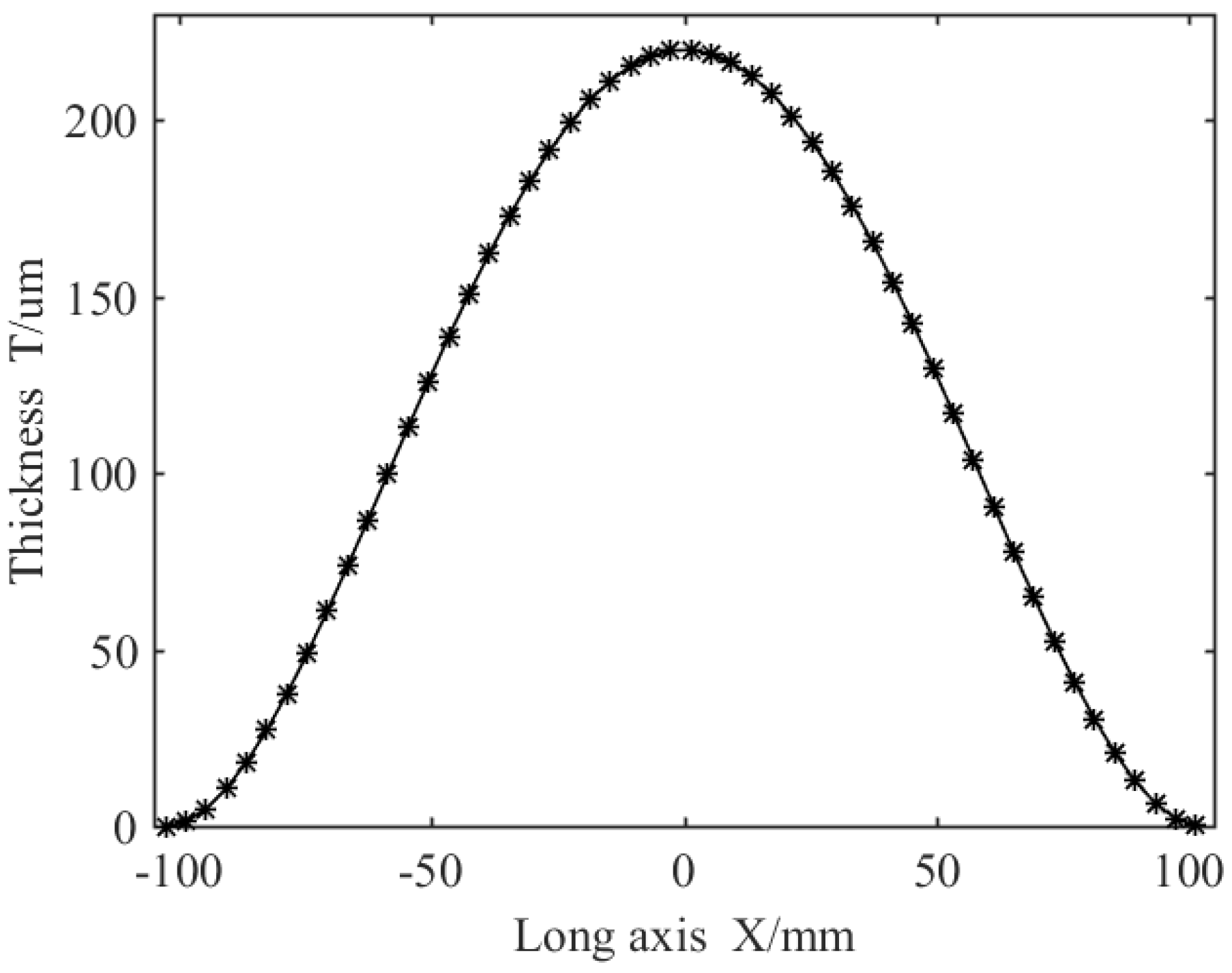
We assumed that an ideal thickness T d of the coating film of 50   µ m . The permissible error of the coating thickness was ± 10   µ m . When the vertical distance d between the spray gun and the large plane of the ship segment was 200 mm, the spraying flow q was 3 L/min. The growth rate coefficient K was 12.2, that is, t m a x was 219.96 um. At the same time, the long radius a was 102.6 mm and the short radius b was 39.9 mm. The above data were inputted into Formula (2) to obtain the instantaneous static growth rate of the coating when the spray gun is sprayed perpendicular to the large plane of the ship segment.
T x , y = 219.96 1 x 2 / 102.6 2 1 y 2 39.9 2 1 x 2 / 102.6 2
Figure 11 displays the curve model for the distribution of paint film coating thickness projected along the long axis of the spray torch in the Z direction when y is equal to 0.
The results showed that d was 83.4 mm and V was 352.6 mm/s. According to Formula (7), the track spacing D was equal to 121.8 mm. Thus, the spray track spacing on the large plane of ship subsection was determined.
Suppose a constant acceleration α equal to 50 mm/s2. When the spraying speed was accelerated from zero to uniform, the time t b was 7.052 s. According to Formula (17), the corresponding speed V n in any time period can be obtained. A series of calculated velocities are V 0 , V 1 , V 2 , V 0 , where V 0 is 0 mm/s and V n is 352.6 mm/s. The spray flow q 0 , q 1 , q 2 , , q n was calculated by the mode search method at each speed. Based on the above data, the distribution of film thickness and coating thickness in acceleration and deceleration with no change in spray gun flow and variable flow spraying were simulated numerically. From Figure 12, the evenly divided sampling of paint film coating thickness was analyzed considering the equal acceleration stage and by sampling and calculating the sampling points. Using a constant flow spray gun, the average thickness of the paint film coating was 56 µm, which is 12% more than the standard thickness; using a variable flow spray gun, the average thickness of the paint film was 51 µm, which is 2% more than the standard thickness. Therefore, the variable flow spray gun improved the stability of the film thickness by nearly 10% and the results indicate that the film thickness distribution was more uniform with a variable flow rate.
In order to verify the correctness of the numerical simulation, SprutCAM software (Version: 16.3.11) was used to simulate the spraying trajectory of the super-large plane of the parts shown. The spray track spacing D was equal to 121.8 mm. Figure 13 shows the spray track of the generated super-large plane.
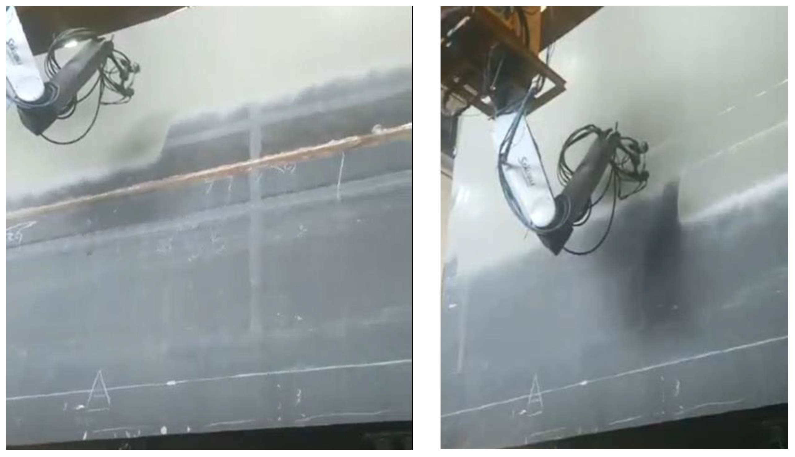
The SprutCAM software parameters were adjusted based on the distance between the spray gun and the surface to be sprayed, the spray range of the gun, and the dynamic spraying speed. Additionally, the film thickness distribution in super-large plane spraying was determined by the static and dynamic spraying flows. The distribution of paint film thickness is shown in Figure 14. Figure 14a shows the spraying effect when the spraying flow in the acceleration and deceleration section was constant. In Figure 14b shows the spraying effect when the spraying flow underwent dynamic changes in the acceleration and deceleration section. Upon comparison, it is evident that the uniformity of film thickness distribution of the dynamic spray gun flow was better than that of the static spray gun flow during acceleration and deceleration, particularly in the case of super-large planes. The red area indicates that the sprayed film thickness deviated greatly from the standard film thickness. These results are consistent with those depicted in Figure 12, thus verifying the effectiveness and feasibility of this method.

5. Experimental Verification

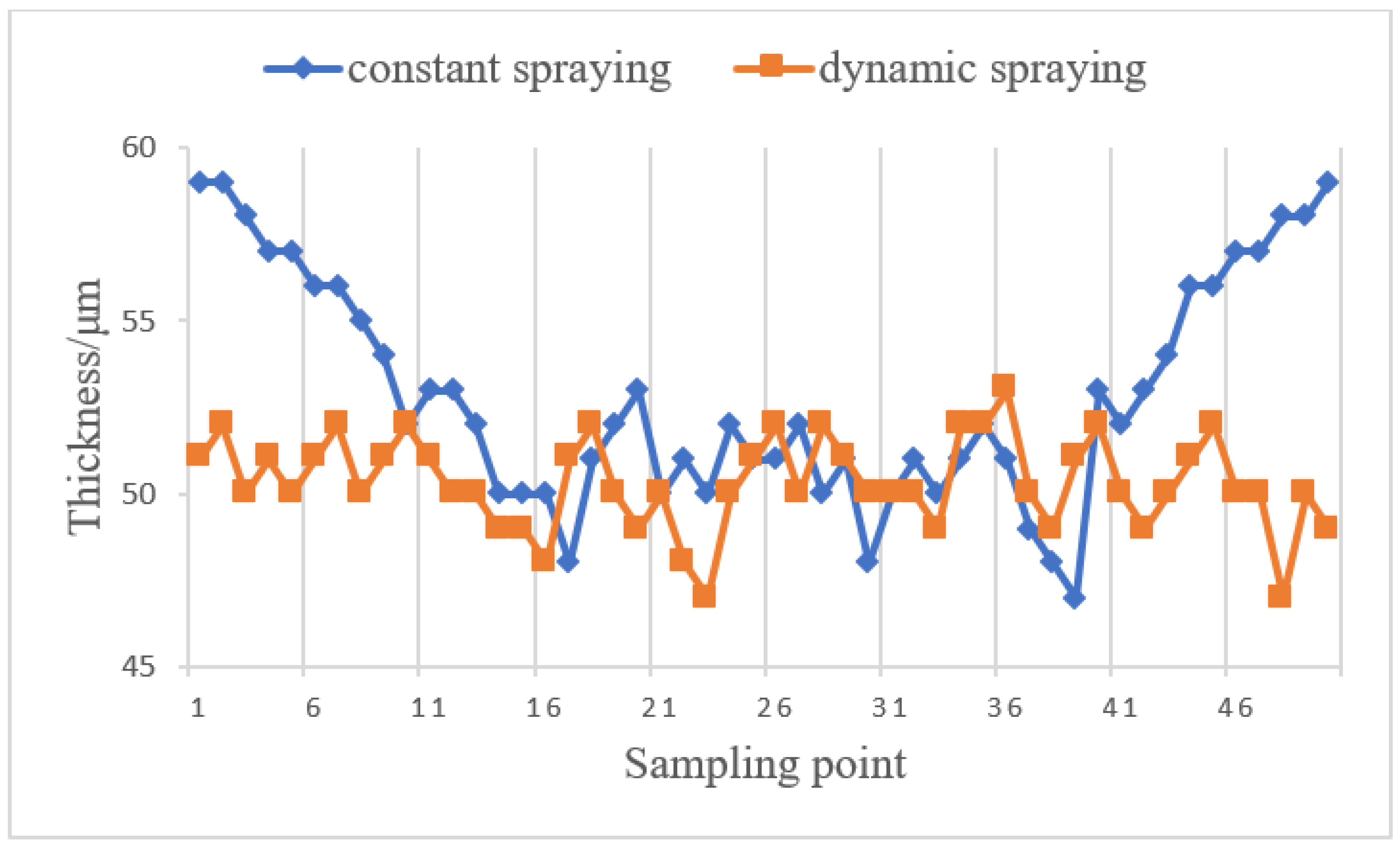
In order to validate the proposed method, a spraying experiment was conducted using the methodology described in this paper. The parameters used in the experiment were kept consistent with those used in the numerical simulation. The spraying results are shown in Figure 15. The coating thickness was measured by taking samples at regular intervals along the length of the super-large plane of the ship section. Multiple measurements were taken at each sampling point along the long axis of the torch to obtain an average value. The coating thickness was measured under two different spraying conditions, and the results are presented in Figure 16. We selected 50 sampling points to analyze the film thickness. We calculated the average film thickness under two modes: dynamic flow and constant flow. We then substituted these values into the root mean square formula to calculate the root mean square values in both cases. According to Table 1, the average film thickness obtained by dynamic flow rate spraying was 50.32   μ m , while the average film thickness obtained by a constant flow rate was 52.86   μ m . The overall average film thickness for dynamic flow rate spraying as closer to the standard value. Similarly, the rms value for dynamic flow spraying was 1.32, while the rms value for constant flow spraying was 3.24. This indicates that the rms value of dynamic flow spraying is smaller, and the film thickness is more uniform. Therefore, the use of dynamic flow spraying can effectively solve the problem of uneven film thickness at the first and last ends. At the same time, the spraying robot based on this method can not only be used for segmental spraying of large-scale ships, but also has considerable prospects for the application in the automotive and aerospace industries.

6. Conclusions

(1)
This study analyzed the pros and cons of two spraying trajectories, the Z-type and spiral spraying trajectories, based on the structure of a large plane of a ship segment. The research established the Z-type trajectory as the optimal spraying trajectory for a super-large plane of a ship segment.
(2)
The elliptic double beta model served as the static model prototype for the spray gun, with the goal of minimizing the coating thickness error. An optimization function was established for spraying speed and spraying trajectory spacing. The maximum uniformity of paint film coating thickness on a large plane of a ship segment was achieved when the acceleration and deceleration section were not taken into consideration.
(3)
The study assumed that the spraying trajectory follows a linear motion of equal acceleration and equal deceleration. Since the acceleration and deceleration sections are symmetric, only cases with equal-acceleration linear motion were considered. The velocity during the constant acceleration phase can be determined using the known spraying velocity, which leads to the mathematical model of the variable flow spray gun. This model enables the determination of a suitable spraying flow rate corresponding to any speed in the acceleration and deceleration sections. A numerical simulation was used to verify the effectiveness and feasibility of the proposed method. In this method, the uniformity of the film thickness can be increased by 10% in the acceleration and deceleration stage, which results in a uniform distribution of paint film thickness on the super-large plane of a ship segment.
(4)
For the spraying of complex structural ship segments, the structural design and control of the ship segmental spraying robot is the basis of the spraying method. However, the existing spraying robots have shortcomings such as a small space for movement, poor obstacle avoidance ability, and false linkage between the mechanical arm and the external axis. Therefore, it is particularly important to carry out the research and design of spraying robots for segmented structural surfaces and non-structural surfaces of ships in the future, so as to make up for the lack of segmented intelligent spraying equipment for ships.

Author Contributions

Methodology, T.S., J.X. and J.C.; conceptualization: L.T. and W.X.; writing—review & editing, J.X.; Investigation, L.T. and Z.W.; data curation, Z.W.; resources and software, J.J. All authors have read and agreed to the published version of the manuscript.

Funding

This research was funded by grant number XTCXKY20230001.

Institutional Review Board Statement

Not applicable.

Informed Consent Statement

Not applicable.

Data Availability Statement

Not applicable.

Conflicts of Interest

The authors declare no conflict of interest.

References

  1. Long, Z.; Li, X.T.; Shuai, T.; Wen, F.J.; Feng, W.R.; Lang, C.P. Review of Research State of Trajectory Planning for Industrial Robots. Mech. Sci. Technol. Aerosp. Eng. 2021, 6, 853–862. [Google Scholar]
  2. Ning, Y.; Meng, M. Analysis and Prospect of Spraying Robot Path Planning Method. Sci. Technol. Eng. 2019, 19, 19–27. [Google Scholar]
  3. Cai, Z.; Liang, H.; Quan, S.; Deng, S.; Zeng, C.; Zhang, F. Computer-aided robot trajectory auto-generation strategy in thermal spraying. J. Therm. Spray Technol. 2015, 24, 1235–1245. [Google Scholar] [CrossRef]
  4. Fang, D.; Zheng, Y.; Zhang, B.; Li, X.; Ju, P.; Li, H.; Zeng, C. Automatic robot trajectory for thermal-sprayed complex Surfaces. Adv. Mater. Sci. Eng. 2018, 2018, 8697056. [Google Scholar] [CrossRef] [Green Version]
  5. Feng, Y.; Yang, Z.; Zeng, Q.; Liu, X.; Hu, X. Research on off-line programming system of marine spraying robot. Mach. Manuf. 2021, 59, 53–59. [Google Scholar]
  6. Chen, Q.; Zou, Y.; Zhang, T.; Zhou, Q. Development of Off—Line Programming System for Spray Robot. Mach. Tool Hydraul. 2013, 41, 122–124. [Google Scholar]
  7. Wang, X.; Sun, K. QT Develop Spraying Robot Off—Line Program Simulation System. Coal Mine Mach. 2016, 37, 188–190. [Google Scholar]
  8. Zeng, Y.; Yu, Y.; Liu, Y.; Liu, D. Parameter Optimization of Boundary-constrained Spray Trajectory for Irregular Plane. Mech. Sci. Technol. Aerosp. Eng. 2020, 39, 904–909. [Google Scholar]
  9. Ma, S.; Luo, X.; Li, A.; Zhou, Y. Painting parametric optimization using AMPSO algorithm on ship painting robots. Chin. J. Constr. Mach. 2016, 14, 125–130. [Google Scholar]
  10. Wang, Y.; Wang, G.; Li, B.; Yan, J.; Lu, D. Analysis of Coating Uniformity in Boundary Zone for Large-Size Surface Spraying. Mech. Sci. Technol. Aerosp. Eng. 2021, 9, 1–8. [Google Scholar]
  11. Lin, M.; Tang, Q.; Li, G.; Luo, Y.; Li, Y.; Fan, Q.; Yang, A.; Zhang, P. Research on Trajectory Planning of Plane Double-pass Spraying Based on Particle Swarm Algorithm. Mech. Eng. 2021, 6, 25–30. [Google Scholar]
  12. Xue-mei, L.I.U.; Tao, L.I.U.; Lian-sheng, Y.A.N.G. Spray Painting Film Thickness Distribution on Panel and Optimization of Width of Paint Film Overlay. Surf. Technol. 2018, 47, 116–125. [Google Scholar]
  13. Qingjun, Z.H.A.N.G.; Yin, X.I.E.; Song, W.U. Prediction of Wave Absorbing Coatings Thickness of Airborne Conformal Antenna Based on Orthogonal Experimental Design and Regression Analysis. Acta Armamentarii 2021, 10, 203–210. [Google Scholar]
  14. Xia, W.; Yu, S.R.; Liao, X.P. Paint deposition pattern modeling and estimation for robotic air spray painting on free-form surface using the curvature circle method. Ind. Robot. 2010, 37, 202–213. [Google Scholar] [CrossRef]
  15. Zhao, D.; Chen, W.; Tang, Y. Tool Path Planning of Spray Painting Robot Based on Genetic Algorithms. China Mech. Eng. 2008, 19, 777–792. [Google Scholar]
  16. Zhang, Y.; Huang, Y.; Gao, F.; Wang, W. New model for air spray gun of robotic spray-painting. Chin. J. Mech. Eng. 2006, 42, 226–233. [Google Scholar] [CrossRef]
  17. Guolei, W.A.N.G.; Qiang, Y.I.; Dongjing, M.I.A.O.; Ken, C.H.E.N.; Liqiang, W.A.N.G. Multivariable coating hickness distribution model for robotic spray painting. J. Tsinghua Univ. Sci. Technol. 2017, 57, 324–330. [Google Scholar]
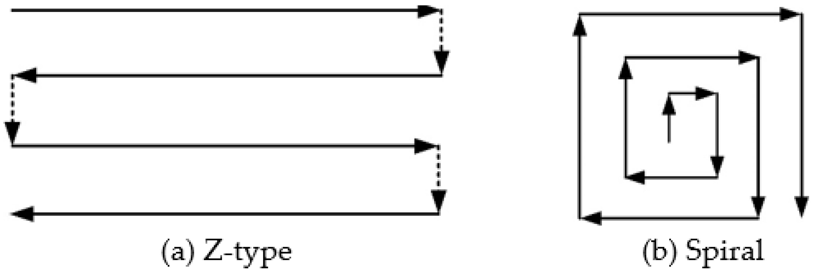
Figure 1. Commonly used large plane spraying trajectory (a) Z-type, (b) spiral spraying trajectory.
Coatings 13 01434 g001
Figure 2. Large plane of a ship segment.
Coatings 13 01434 g002
Figure 3. Speed division of Z-shaped spray trajectory.
Coatings 13 01434 g003
Figure 4. Paint film thickness distribution without considering acceleration and deceleration.
Coatings 13 01434 g004
Figure 5. Schematic diagram of spray gun spraying.
Coatings 13 01434 g005
Figure 6. Elliptical double beta model.
Coatings 13 01434 g006
Figure 7. Dynamic spraying of spray gun along linear spraying trajectory.
Coatings 13 01434 g007
Figure 8. Superposition of two oval torches with adjacent spray tracks.
Coatings 13 01434 g008
Figure 9. Relationship between time and spraying speed.
Coatings 13 01434 g009
Figure 10. Velocity corresponding to the position of the torch at any time.
Coatings 13 01434 g010
Figure 11. Film coating thickness distribution projected by long axis spray in Z direction.
Coatings 13 01434 g011
Figure 12. Paint film thickness distribution at different sampling points. (a) Paint film thickness distribution of spraying gun at a constant flow in the acceleration and deceleration section of spraying. (b) Paint film thickness distribution of variable flow spraying gun in acceleration and deceleration section of spraying.
Coatings 13 01434 g012
Figure 13. Planning and simulation of spraying trajectory of a certain section on a super-large plane.
Coatings 13 01434 g013
Figure 14. Uniform distribution effect of paint film thickness using constant flow rate of spray gun and dynamic spraying: (a) constant spraying flow; (b) dynamic spraying flow.
Coatings 13 01434 g014
Figure 15. Variable gun flow rate spraying process and effect.
Coatings 13 01434 g015
Figure 16. Data sampling diagram.
Coatings 13 01434 g016
Table 1. Spray gun constant flow rate spraying and dynamic flow rate spraying thickness data.
DATA Thickness   ( μ m )
standard (target) values50
mean thickness (constant spraying)52.86
mean thickness (dynamic spraying)50.32
rms thickness (constant spraying)3.24
rms thickness (dynamic spraying)1.32
Disclaimer/Publisher’s Note: The statements, opinions and data contained in all publications are solely those of the individual author(s) and contributor(s) and not of MDPI and/or the editor(s). MDPI and/or the editor(s) disclaim responsibility for any injury to people or property resulting from any ideas, methods, instructions or products referred to in the content.