
Recent Advances in Metal–Organic Frameworks for the Surface Modification of the Zinc Metal Anode: A Review

Abstract
:1. Introduction
2. Zn-Based MOF
2.1. Pristine Zn MOF
2.2. Zn MOF Derivatives
3. Zr-Based MOF
4. Other Typical MOF

| Interfacial Layers | Preparation Methods | Voltage Hysteresis V a (V) (C1 c (mA cm−2 )) | Lifespan T b h [C1 c (mA cm−2), C2 c (mAh cm−2)] | Ref. |
|---|---|---|---|---|
| Zn MOF | ||||
| ZIF-7 | Doctor blading method | 0.028 (0.3) | 3000 (0.5,0.5) | [50] |
| ZIF-8 | One-step solvent thermal method | 0.058 (2) | 1200 (2,1) | [61] |
| ZIF-8 | Vapor–solid reaction | / | 3000 (1,1) | [62] |
| Zn-MOF | On-site chemical coordination | 0.080 (4) | 2100 (4,2) | [63] |
| Zn-BTC | Doctor blade method | / | 400 (4,1) | [64] |
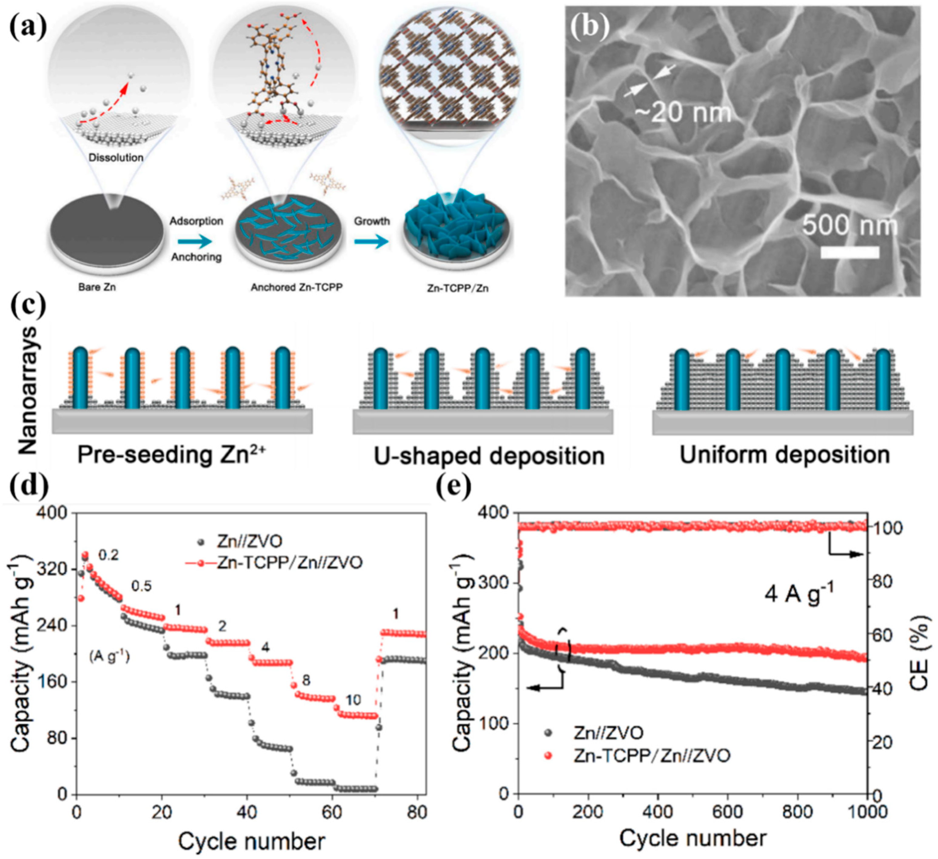
| Zn-TCPP | Self-template method | 0.050 (5) | 2600 (0.2,0.2) | [66] |
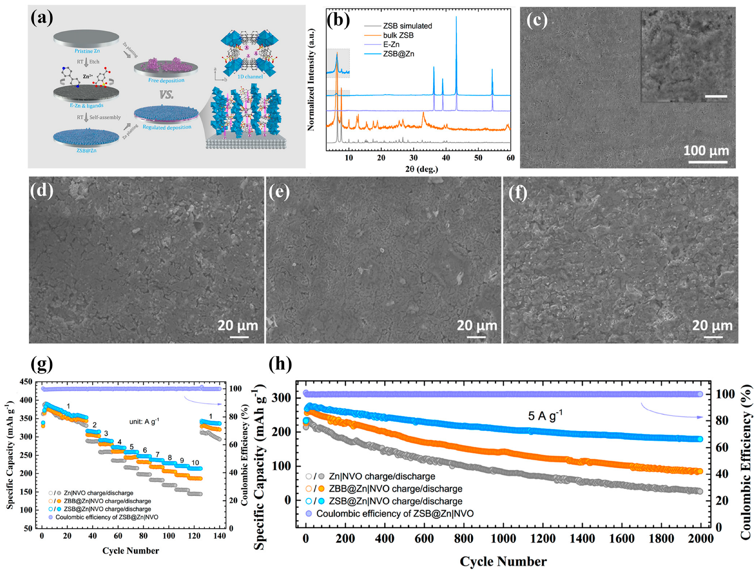
| ZSB | In situ growth | / | 3100 (5,2.5) | [51] |
| ZIF-L | In situ growth | 0.026 (0.25) | 800 (0.25,0.25) | [65] |
| ZIF-8 derived carbon materials | In situ growth and pyrolyzing | / | / | [69] |
| CuZn@C | Coating | ~0.025 (2) | 500 (1,1) | [70] |
| Zr MOF | ||||
| UIO-67-2D | Drop-casting | 0.018 (0.25) | 850 (0.5,0.5) | [72] |
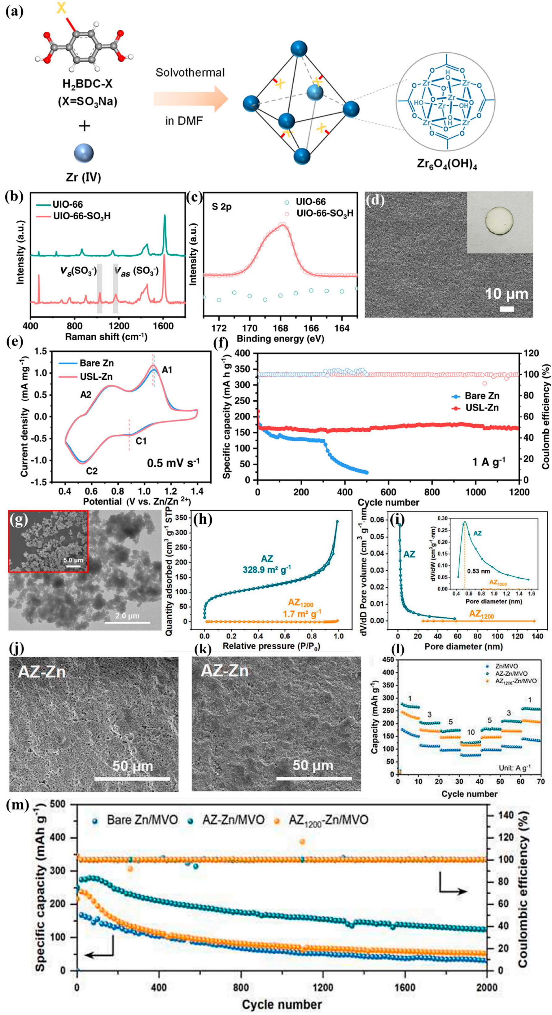
| UIO-66-SO3H | Drop-casting | ~0.040 (1) | 700 (5,5) | [52] |
| UIO-66-(COOH)2 | Manually coating | 0.080 (10) | 240 (10,/) | [76] |
| ATMP-Zr | Doctor blade method | 0.032 (1) | 1800 (1,1) | [53] |
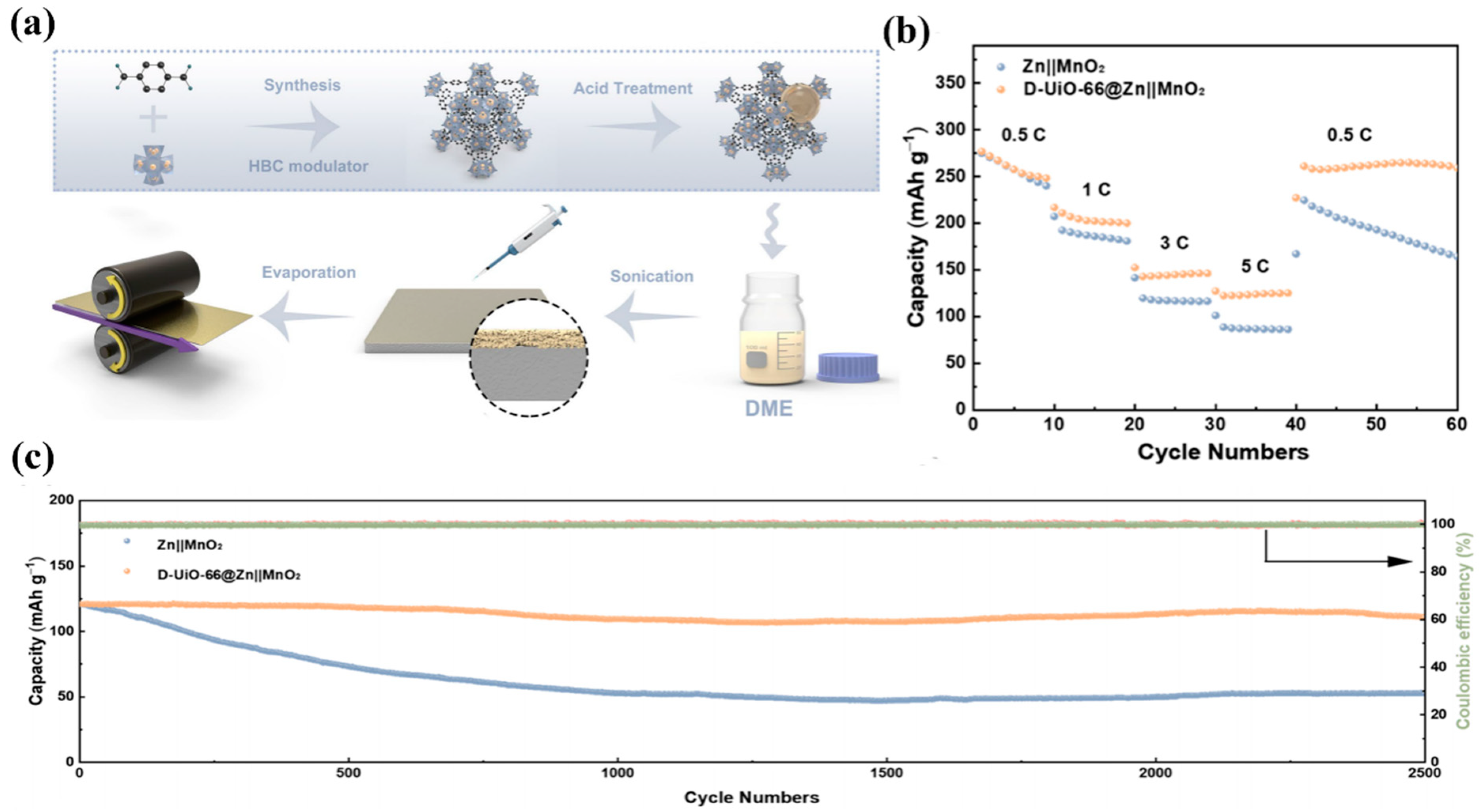
| D-UIO-66 | Rolling process | 0.066 (1) | 1800 (1,1) | [79] |
| UIO-66 | Coating | / | 100 (3,3) | [73] |
| Other Typical MOF | ||||
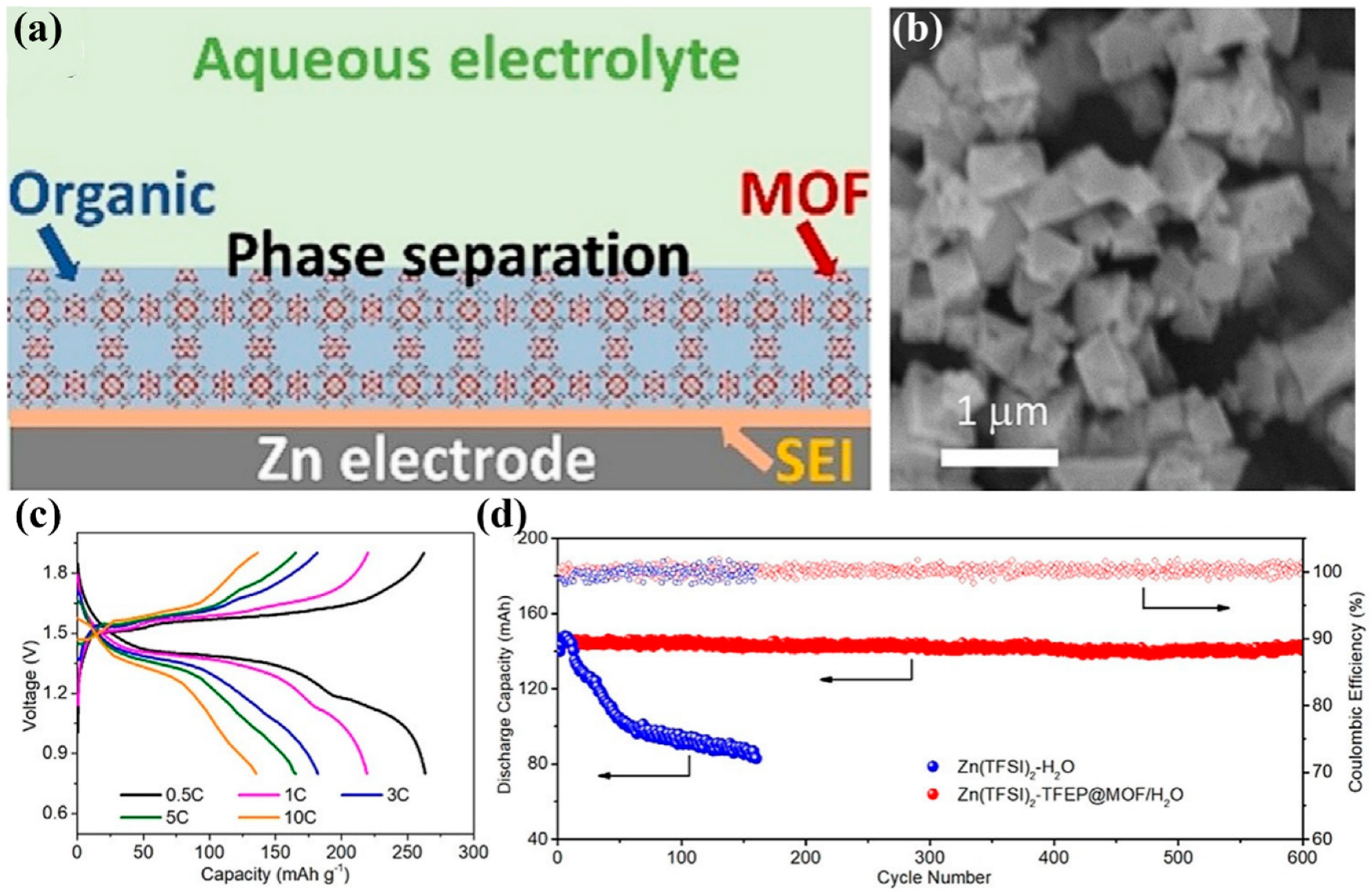
| Cu3(BTC)2 MOF filled with Zn(TFSI)2-TFEP@Zn | Coating | 0.020 (0.5) | 700 (0.5,0.5) | [81] |
| SCM | Hydrothermal and selenization | / | 500 (2,1) | [80] |
| 2D Mn-MOF | Squeegee method | ~0.0446 mV (4) | 2000 (4,4) | [82] |
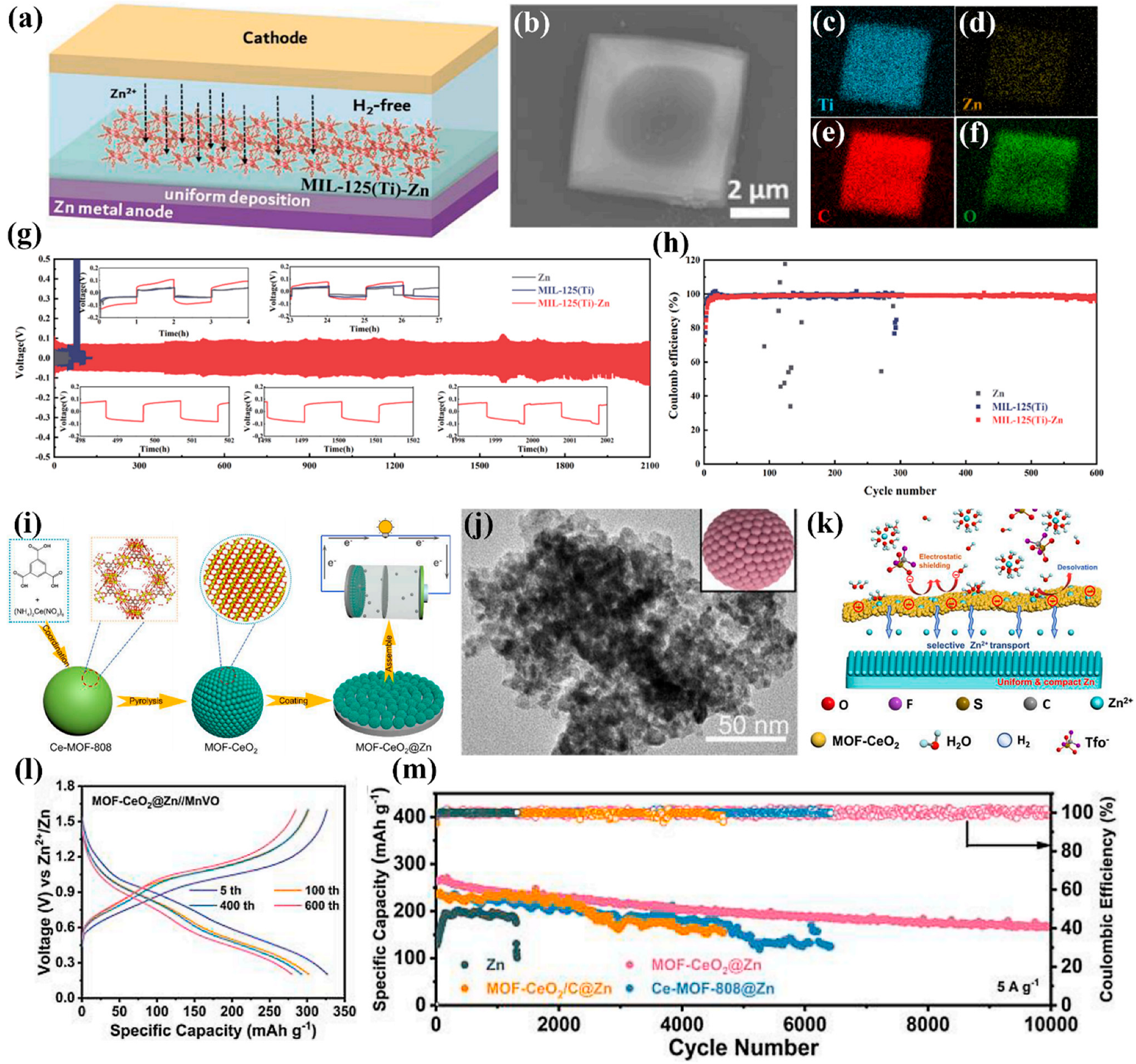
| MIL-125(Ti)-Zn | Coating | ~0.080 (1) | 2100 (1,1) | [84] |
| MIL-125(Ti) | Scraper method | / | 4200 (1,1) | [83] |
| MOF-CeO2 | Spin-coating | / | 3200 (3,1) | [85] |
5. Conclusions and Outlook
- Develop novel types and functions of MOFs for the surface modification of the Zn anode. Up to now, tens of thousands of MOFs have been designed and fabricated, but only a few dozen are used for the coating materials of Zn anodes in AZIBs. The research on MOFs on the surface modification of the Zn anode is still in the early stage, and more kinds of MOFs need to be explored. As a coating material used in AZIBs, MOFs should be continuously immersed in an aqueous electrolyte, which requires MOFs to have a high water stability. However, most MOFs are less stable in water systems [56]. The MOFs with a high valence metal as the node have stronger coordination bonds and a larger coordination number, which endows it a more stable structure, and the stable structure allows it to accommodate a variety of treatments. Therefore, MOFs with a hypervalent metal center may be the future development trend of Zn anode coating materials. Additionally, it is necessary to explore the new functions and properties of the MOFs that have been applied in practice.
- Explore new composites of MOF coating materials. Although the use of bare MOFs as an interfacial protective coating material for the Zn anode has achieved good results, the exploration of MOF composite materials should be paid attention to. By combining MOFs with other functional materials, the materials with desired properties can be obtained. For example, most MOFs have a low electrical conductivity. By creating composites with conductive carbon materials, coating materials with a high conductivity can be obtained, which helps to reduce the charge accumulation and homogenize the electric field distribution on the Zn anode surface.
- Develop reliable, convenient, and low-cost synthesis strategies. At present, most of the MOF derivatives used for the surface modification of the Zn anode are prepared by calcination, in which the MOF derivatives are prone to structural collapse [55]. Therefore, reliable preparation techniques are needed to maintain the porous structure after annealing. Additionally, cost is an important consideration for commercialization. Although the cost of zinc is low, the synthesis and modification of MOFs will increase the material consumption and process complexity. Some organic ligands are expensive and have a low practical application value. Thus, in the preparation of MOFs, priority should be given to low-cost, environmentally friendly organic ligands and simple synthesis methods.
- Reveal the mechanism. AZIBs exhibit excellent performance by the surface modification of the Zn anode with MOFs, but the mechanisms of MOFs are still unclear. Most of the current characterization techniques are ex situ characterizations, which cannot well reveal the changes in the composition and structure of MOFs during the cycle. Hence, it is necessary to develop in situ characterization techniques as well as use theoretical simulation and calculation to provide an in-depth understanding and theoretical basis for the mechanism of MOFs.
Author Contributions
Funding
Institutional Review Board Statement
Informed Consent Statement
Data Availability Statement
Conflicts of Interest
References
- Zhao, T.; Wu, H.; Wen, X.; Zhang, J.; Tang, H.; Deng, Y.; Liao, S.; Tian, X. Recent advances in MOFs/MOF derived nanomaterials toward high-efficiency aqueous zinc ion batteries. Coord. Chem. Rev. 2022, 468, 214642. [Google Scholar] [CrossRef]
- Chu, S.; Majumdar, A. Opportunities and challenges for a sustainable energy future. Nature 2012, 488, 294–303. [Google Scholar] [CrossRef] [PubMed]
- Turner, J.M. The matter of a clean energy future. Science 2022, 376, 1361. [Google Scholar] [CrossRef]
- Qian, H.; Liu, Y.; Chen, H.; Feng, K.; Jia, K.; Pan, K.; Wang, G.; Huang, T.; Pang, X.; Zhang, Q. Emerging bismuth-based materials: From fundamentals to electrochemical energy storage applications. Energy Storage Mater. 2023, 58, 232–270. [Google Scholar] [CrossRef]
- Wang, H.; Zhu, Q.-L.; Zou, R.; Xu, Q. Metal-Organic Frameworks for Energy Applications. Chem 2017, 2, 52–80. [Google Scholar] [CrossRef]
- Thackeray, M.M.; Wolverton, C.; Isaacs, E.D. Electrical energy storage for transportation-approaching the limits of, and going beyond, lithium-ion batteries. Energy Environ. Sci. 2012, 5, 7854–7863. [Google Scholar] [CrossRef]
- Yin, J.; Feng, X.; Gan, Z.; Gao, Y.; Cheng, Y.; Xu, X. From anode to cell: Synergistic protection strategies and perspectives for stabilized Zn metal in mild aqueous electrolytes. Energy Storage Mater. 2023, 54, 623–640. [Google Scholar] [CrossRef]
- Zhou, J.; Yang, Q.; Xie, Q.; Ou, H.; Lin, X.; Zeb, A.; Hu, L.; Wu, Y.; Ma, G. Recent progress in Co-based metal-organic framework derivatives for advanced batteries. J. Mater. Sci. Technol. 2022, 96, 262–284. [Google Scholar] [CrossRef]
- Gur, T.M. Review of electrical energy storage technologies, materials and systems: Challenges and prospects for large-scale grid storage. Energy Environ. Sci. 2018, 11, 2696–2767. [Google Scholar] [CrossRef]
- Liu, Z.; Ha, S.; Liu, Y.; Wang, F.; Tao, F.; Xu, B.; Yu, R.; Wang, G.; Ren, F.; Li, H. Application of Ag-based materials in high-performance lithium metal anode: A review. J. Mater. Sci. Technol. 2023, 133, 165–182. [Google Scholar] [CrossRef]
- Miao, Y.; Zheng, Y.; Tao, F.; Chen, Z.; Xiong, Y.; Ren, F.; Liu, Y. Synthesis and application of single-atom catalysts in sulfur cathode for high-performance lithium-sulfur batteries. Chin. Chem. Lett. 2023, 34, 107121. [Google Scholar] [CrossRef]
- Yang, Z.; Zhang, J.; Kintner-Meyer, M.C.; Lu, X.; Choi, D.; Lemmon, J.P.; Liu, J. Electrochemical energy storage for green grid. Chem. Rev. 2011, 111, 3577–3613. [Google Scholar] [CrossRef] [PubMed]
- Feng, K.; Sun, Z.; Liu, Y.; Tao, F.; Ma, J.; Qian, H.; Yu, R.; Pan, K.; Wang, G.; Wei, S.; et al. Shining light on transition metal tungstate-based nanomaterials for electrochemical applications: Structures, progress, and perspectives. Nano Res. 2022, 15, 6924–6960. [Google Scholar] [CrossRef]
- Yuan, M.; Guo, X.; Liu, Y.; Pang, H. Si-based materials derived from biomass: Synthesis and applications in electrochemical energy storage. J. Mater. Chem. A 2019, 7, 22123–22147. [Google Scholar] [CrossRef]
- Wang, F.; Liu, Y.; Wei, H.-J.; Li, T.-F.; Xiong, X.-H.; Wei, S.-Z.; Ren, F.-Z.; Volinsky, A.A. Recent advances and perspective in metal coordination materials-based electrode materials for potassium-ion batteries. Rare Met. 2021, 40, 448–470. [Google Scholar] [CrossRef]
- Etacheri, V.; Marom, R.; Elazari, R.; Salitra, G.; Aurbach, D. Challenges in the development of advanced Li-ion batteries: A review. Energy Environ. Sci. 2011, 4, 3243–3262. [Google Scholar] [CrossRef]
- Goodenough, J.B.; Kim, Y. Challenges for Rechargeable Li Batteries. Chem. Mater. 2009, 22, 587–603. [Google Scholar] [CrossRef]
- Bruce, P.G.; Scrosati, B.; Tarascon, J.M. Nanomaterials for rechargeable lithium batteries. Angew. Chem. Int. Ed. Engl. 2008, 47, 2930–2946. [Google Scholar] [CrossRef]
- Bravo Diaz, L.; He, X.; Hu, Z.; Restuccia, F.; Marinescu, M.; Barreras, J.V.; Patel, Y.; Offer, G.; Rein, G. Review—Meta-Review of Fire Safety of Lithium-Ion Batteries: Industry Challenges and Research Contributions. J. Electrochem. Soc. 2020, 167, 090559. [Google Scholar] [CrossRef]
- Wang, F.; Gao, J.; Liu, Y.; Ren, F. An amorphous ZnO and oxygen vacancy modified nitrogen-doped carbon skeleton with lithiophilicity and ionic conductivity for stable lithium metal anodes. J. Mater. Chem. A 2022, 10, 17395–17405. [Google Scholar] [CrossRef]
- Zhang, N.; Chen, X.; Yu, M.; Niu, Z.; Cheng, F.; Chen, J. Materials chemistry for rechargeable zinc-ion batteries. Chem. Soc. Rev. 2020, 49, 4203–4219. [Google Scholar] [CrossRef]
- Yang, D.; Zhou, Y.; Geng, H.; Liu, C.; Lu, B.; Rui, X.; Yan, Q. Pathways towards high energy aqueous rechargeable batteries. Coord. Chem. Rev. 2020, 424, 213521. [Google Scholar] [CrossRef]
- Luo, J.Y.; Cui, W.J.; He, P.; Xia, Y.Y. Raising the cycling stability of aqueous lithium-ion batteries by eliminating oxygen in the electrolyte. Nat. Chem. 2010, 2, 760–765. [Google Scholar] [CrossRef]
- Liu, Y.; Wei, H.; Zhai, X.; Wang, F.; Ren, X.; Xiong, Y.; Pan, K.; Ren, F.; Wei, S. Graphene-based interlayer for high-performance lithium–sulfur batteries: A review. Mater. Des. 2021, 211, 110171. [Google Scholar] [CrossRef]
- Liu, S.; Zhang, R.; Mao, J.; Zhao, Y.; Cai, Q.; Guo, Z. From room temperature to harsh temperature applications: Fundamentals and perspectives on electrolytes in zinc metal batteries. Sci. Adv. 2022, 8, eabn5097. [Google Scholar] [CrossRef]
- Xu, C.; Li, B.; Du, H.; Kang, F. Energetic zinc ion chemistry: The rechargeable zinc ion battery. Angew. Chem. Int. Ed. Engl. 2012, 51, 933–935. [Google Scholar] [CrossRef]
- Song, M.; Zhong, C.-L. Achieving both high reversible and stable Zn anode by a practical glucose electrolyte additive toward high-performance Zn-ion batteries. Rare Met. 2022, 41, 356–360. [Google Scholar] [CrossRef]
- Jia, H.; Wang, Z.; Tawiah, B.; Wang, Y.; Chan, C.-Y.; Fei, B.; Pan, F. Recent advances in zinc anodes for high-performance aqueous Zn-ion batteries. Nano Energy 2020, 70, 104523. [Google Scholar] [CrossRef]
- Liu, X.; Lu, Q.; Yang, A.; Qian, Y. High ionic conductive protection layer on Zn metal anode for enhanced aqueous zinc-ion batteries. Chin. Chem. Lett. 2023, 34, 107703. [Google Scholar] [CrossRef]
- Wu, Y.; Song, T.-Y.; Chen, L.-N. A review on recent developments of vanadium-based cathode for rechargeable zinc-ion batteries. Tungsten 2021, 3, 289–304. [Google Scholar] [CrossRef]
- Yang, Q.; Li, Q.; Liu, Z.; Wang, D.; Guo, Y.; Li, X.; Tang, Y.; Li, H.; Dong, B.; Zhi, C. Dendrites in Zn-Based Batteries. Adv. Mater. 2020, 32, 2001854. [Google Scholar] [CrossRef] [PubMed]
- Hong, L.; Wang, L.Y.; Wang, Y.; Wu, X.; Huang, W.; Zhou, Y.; Wang, K.X.; Chen, J.S. Toward Hydrogen-Free and Dendrite-Free Aqueous Zinc Batteries: Formation of Zincophilic Protective Layer on Zn Anodes. Adv. Sci. 2022, 9, 2104866. [Google Scholar] [CrossRef] [PubMed]
- Tang, B.; Shan, L.; Liang, S.; Zhou, J. Issues and opportunities facing aqueous zinc-ion batteries. Energy Environ. Sci. 2019, 12, 3288–3304. [Google Scholar] [CrossRef]
- Feng, D.; Cao, F.; Hou, L.; Li, T.; Jiao, Y.; Wu, P. Immunizing Aqueous Zn Batteries against Dendrite Formation and Side Reactions at Various Temperatures via Electrolyte Additives. Small 2021, 17, 2103195. [Google Scholar] [CrossRef] [PubMed]
- Hao, Z.; Wu, Y.; Zhao, Q.; Tang, J.; Zhang, Q.; Ke, X.; Liu, J.; Jin, Y.; Wang, H. Functional Separators Regulating Ion Transport Enabled by Metal-Organic Frameworks for Dendrite-Free Lithium Metal Anodes. Adv. Funct. Mater. 2021, 31, 2102938. [Google Scholar] [CrossRef]
- Zhu, D.; Zheng, Y.; Xiong, Y.; Cui, C.; Ren, F.; Liu, Y. In situ growth of S-doped ZnO thin film enabling dendrite-free zinc anode for high-performance aqueous zinc-ion batteries. J. Alloys Compd. 2022, 918, 165486. [Google Scholar] [CrossRef]
- Zhai, P.; Zhai, X.; Jia, Z.; Zhang, W.; Pan, K.; Liu, Y. Inhibiting corrosion and side reactions of zinc metal anode by nano-CaSiO3 coating towards high-performance aqueous zinc-ion batteries. Nanotechnology 2023, 34, 085402. [Google Scholar] [CrossRef]
- Kang, Z.; Wu, C.; Dong, L.; Liu, W.; Mou, J.; Zhang, J.; Chang, Z.; Jiang, B.; Wang, G.; Kang, F.; et al. 3D Porous Copper Skeleton Supported Zinc Anode toward High Capacity and Long Cycle Life Zinc Ion Batteries. ACS Sustain. Chem. Eng. 2019, 7, 3364–3371. [Google Scholar] [CrossRef]
- Liu, Y.; Tao, F.; Xing, Y.; Pei, Y.; Ren, F. Melamine Foam-Derived Carbon Scaffold for Dendrite-Free and Stable Zinc Metal Anode. Molecules 2023, 28, 1742. [Google Scholar] [CrossRef]
- Tao, F.; Liu, Y.; Ren, X.; Wang, J.; Zhou, Y.; Miao, Y.; Ren, F.; Wei, S.; Ma, J. Different surface modification methods and coating materials of zinc metal anode. J. Energy Chem. 2022, 66, 397–412. [Google Scholar] [CrossRef]
- Tao, F.; Feng, K.; Liu, Y.; Ren, J.; Xiong, Y.; Li, C.; Ren, F. Suppressing interfacial side reactions of zinc metal anode via isolation effect toward high-performance aqueous zinc-ion batteries. Nano Res. 2023, 16, 6789–6797. [Google Scholar] [CrossRef]
- Xie, C.; Zhang, Q.; Yang, Z.; Ji, H.; Li, Y.; Li, H.; Fu, L.; Huang, D.; Tang, Y.; Wang, H. Intrinsically zincophobic protective layer for dendrite-free zinc metal anode. Chin. Chem. Lett. 2022, 33, 2653–2657. [Google Scholar] [CrossRef]
- Wang, L.; Han, Y.; Feng, X.; Zhou, J.; Qi, P.; Wang, B. Metal–organic frameworks for energy storage: Batteries and supercapacitors. Coord. Chem. Rev. 2016, 307, 361–381. [Google Scholar] [CrossRef]
- Ferey, G. Hybrid porous solids: Past, present, future. Chem. Soc. Rev. 2008, 37, 191–214. [Google Scholar] [CrossRef]
- Xu, Y.; Li, Q.; Xue, H.; Pang, H. Metal-organic frameworks for direct electrochemical applications. Coord. Chem. Rev. 2018, 376, 292–318. [Google Scholar] [CrossRef]
- Xie, Z.; Xu, W.; Cui, X.; Wang, Y. Recent Progress in Metal-Organic Frameworks and Their Derived Nanostructures for Energy and Environmental Applications. ChemSusChem 2017, 10, 1645–1663. [Google Scholar] [CrossRef]
- Hu, X.; Hu, H.; Li, C.; Li, T.; Lou, X.; Chen, Q.; Hu, B. Cobalt-based metal organic framework with superior lithium anodic performance. J. Solid State Chem. 2016, 242, 71–76. [Google Scholar] [CrossRef]
- Zhang, S.; Li, X.; Ding, B.; Li, H.; Liu, X.; Xu, Q. A novel spitball-like Co3(NO3)2(OH)4@Zr-MOF@RGO anode material for sodium-ion storage. J. Alloys Compd. 2020, 822, 153624. [Google Scholar] [CrossRef]
- Jiao, Y.; Pei, J.; Yan, C.; Chen, D.; Hu, Y.; Chen, G. Layered nickel metal–organic framework for high performance alkaline battery-supercapacitor hybrid devices. J. Mater. Chem. A 2016, 4, 13344–13351. [Google Scholar] [CrossRef]
- Yang, H.; Chang, Z.; Qiao, Y.; Deng, H.; Mu, X.; He, P.; Zhou, H. Constructing a Super-Saturated Electrolyte Front Surface for Stable Rechargeable Aqueous Zinc Batteries. Angew. Chem. Int. Ed. 2020, 59, 9377–9381. [Google Scholar] [CrossRef]
- Wang, Z.; Chen, H.; Wang, H.; Huang, W.; Li, H.; Pan, F. In Situ Growth of a Metal–Organic Framework-Based Solid Electrolyte Interphase for Highly Reversible Zn Anodes. ACS Energy Lett. 2022, 7, 4168–4176. [Google Scholar] [CrossRef]
- Fan, H.; Li, M.; Wang, E. Anion-functionalized interfacial layer for stable Zn metal anodes. Nano Energy 2022, 103, 107751. [Google Scholar] [CrossRef]
- Ren, J.; Li, C.; Li, P.; Liu, S.; Wang, L. Amorphous MOF as smart artificial solid/electrolyte interphase for highly-stable Zn-ion batteries. Chem. Eng. J. 2023, 462, 142270. [Google Scholar] [CrossRef]
- Xu, X.; Chen, Y.; Liu, D.; Zheng, D.; Dai, X.; Shi, W.; Cao, X. Metal-Organic Framework-Based Materials for Aqueous Zinc-Ion Batteries: Energy Storage Mechanism and Function. Chem. Rec. 2022, 22, e202200079. [Google Scholar] [CrossRef]
- Peng, Y.; Xu, J.; Xu, J.; Ma, J.; Bai, Y.; Cao, S.; Zhang, S.; Pang, H. Metal-organic framework (MOF) composites as promising materials for energy storage applications. Adv. Colloid Interface Sci. 2022, 307, 102732. [Google Scholar] [CrossRef] [PubMed]
- Tan, H.; Zhou, Y.; Qiao, S.-Z.; Fan, H.J. Metal organic framework (MOF) in aqueous devices. Mater. Today 2021, 48, 270–284. [Google Scholar] [CrossRef]
- Yuan, S.; Qin, J.S.; Lollar, C.T.; Zhou, H.C. Stable Metal-Organic Frameworks with Group 4 Metals: Current Status and Trends. ACS Cent. Sci. 2018, 4, 440–450. [Google Scholar] [CrossRef]
- Guo, X.; Wang, L.; Wang, L.; Huang, Q.; Bu, L.; Wang, Q. Metal-organic frameworks for food contaminant adsorption and detection. Front. Chem. 2023, 11, 1116524. [Google Scholar] [CrossRef]
- Ivanova, B.; Spiteller, M. Electrospray ionization mass spectrometric solvate cluster and multiply charged ions: A stochastic dynamic approach to 3D structural analysis. SN Appl. Sci. 2020, 2, 731. [Google Scholar] [CrossRef]
- Wang, X.; Wan, Y.; Hu, W.; Chou, I.M.; Cao, J.; Wang, X.; Wang, M.; Li, Z. In situ observations of liquid–liquid phase separation in aqueous ZnSO4 solutions at temperatures up to 400 °C: Implications for Zn2+–SO42− association and evolution of submarine hydrothermal fluids. Geochim. Cosmochim. Acta 2016, 181, 126–143. [Google Scholar] [CrossRef]
- Liu, X.; Yang, F.; Xu, W.; Zeng, Y.; He, J.; Lu, X. Zeolitic Imidazolate Frameworks as Zn2+ Modulation Layers to Enable Dendrite-Free Zn Anodes. Adv. Sci. 2020, 7, 2002173. [Google Scholar] [CrossRef] [PubMed]
- Luo, X.; Nian, Q.; Wang, Z.; Xiong, B.-Q.; Chen, S.; Li, Y.; Ren, X. Building a seamless water-sieving MOF-based interphase for highly reversible Zn metal anodes. Chem. Eng. J. 2023, 455, 140510. [Google Scholar] [CrossRef]
- Sun, H.; Huyan, Y.; Li, N.; Lei, D.; Liu, H.; Hua, W.; Wei, C.; Kang, F.; Wang, J.-G. A Seamless Metal–Organic Framework Interphase with Boosted Zn2+ Flux and Deposition Kinetics for Long-Living Rechargeable Zn Batteries. Nano Lett. 2023, 23, 1726–1734. [Google Scholar] [CrossRef] [PubMed]
- Wang, Y.; Liu, Y.; Wang, H.; Dou, S.; Gan, W.; Ci, L.; Huang, Y.; Yuan, Q. MOF-based ionic sieve interphase for regulated Zn2+ flux toward dendrite-free aqueous zinc-ion batteries. J. Mater. Chem. A 2022, 10, 4366–4375. [Google Scholar] [CrossRef]
- He, W.; Gu, T.; Xu, X.; Zuo, S.; Shen, J.; Liu, J.; Zhu, M. Uniform In Situ Grown ZIF-L Layer for Suppressing Hydrogen Evolution and Homogenizing Zn Deposition in Aqueous Zn-Ion Batteries. ACS Appl. Mater. Interfaces 2022, 14, 40031–40042. [Google Scholar] [CrossRef] [PubMed]
- Wang, F.; Lu, H.; Li, H.; Li, J.; Wang, L.; Han, D.; Gao, J.; Geng, C.; Cui, C.; Zhang, Z.; et al. Demonstrating U-shaped zinc deposition with 2D metal-organic framework nanoarrays for dendrite-free zinc batteries. Energy Storage Mater. 2022, 50, 641–647. [Google Scholar] [CrossRef]
- Hu, Y.Y.; Han, R.X.; Mei, L.; Liu, J.L.; Sun, J.C.; Yang, K.; Zhao, J.W. Design principles of MOF-related materials for highly stable metal anodes in secondary metal-based batteries. Mater. Today Energy 2021, 19, 100608. [Google Scholar] [CrossRef]
- Cong, C.; Ma, H. Advances of Electroactive Metal–Organic Frameworks. Small 2023, 19, 2207547. [Google Scholar] [CrossRef]
- Yuksel, R.; Buyukcakir, O.; Seong, W.K.; Ruoff, R.S. Metal-Organic Framework Integrated Anodes for Aqueous Zinc-Ion Batteries. Adv. Energy Mater. 2020, 10, 1904215. [Google Scholar] [CrossRef]
- Yuan, G.; Liu, Y.-Y.; Xia, J.; Su, Y.; Wei, W.; Zhu, Y.; An, Y.; Wu, H.; Xu, Q.; Pang, H. Two-dimensional CuO nanosheets-induced MOF composites and derivatives for dendrite-free zinc-ion batteries. Nano Res. 2023, 16, 6881–6889. [Google Scholar] [CrossRef]
- Cavka, J.H.; Jakobsen, S.; Olsbye, U.; Guillou, N.; Lamberti, C.; Bordiga, S.; Lillerud, K.P. A New Zirconium Inorganic Building Brick Forming Metal Organic Frameworks with Exceptional Stability. J. Am. Chem. Soc. 2008, 130, 13850–13851. [Google Scholar] [CrossRef]
- Lei, L.; Chen, F.; Wu, Y.; Shen, J.; Wu, X.-J.; Wu, S.; Yuan, S. Surface coatings of two-dimensional metal-organic framework nanosheets enable stable zinc anodes. Sci. China Chem. 2022, 65, 2205–2213. [Google Scholar] [CrossRef]
- Liu, M.Q.; Yang, L.Y.; Liu, H.; Amine, A.; Zhao, Q.H.; Song, Y.L.; Yang, J.L.; Wang, K.; Pan, F. Artificial Solid-Electrolyte Interface Facilitating Dendrite-Free Zinc Metal Anodes via Nanowetting Effect. ACS Appl. Mater. Interfaces 2019, 11, 32046–32051. [Google Scholar] [CrossRef]
- Zou, D.; Liu, D. Understanding the modifications and applications of highly stable porous frameworks via UiO-66. Mater. Today Chem. 2019, 12, 139–165. [Google Scholar] [CrossRef]
- Rego, R.M.; Kurkuri, M.D.; Kigga, M. A comprehensive review on water remediation using UiO-66 MOFs and their derivatives. Chemosphere 2022, 302, 134845. [Google Scholar] [CrossRef] [PubMed]
- Kim, E.; Choi, I.; Nam, K.W. Metal–organic framework for dendrite-free anodes in aqueous rechargeable zinc batteries. Electrochim. Acta 2022, 425, 140648. [Google Scholar] [CrossRef]
- Wei, K.; Wang, X.; Jiao, X.; Li, C.; Chen, D. Self-supported three-dimensional macroporous amorphous NiFe bimetallic-organic frameworks for enhanced water oxidation. Appl. Surf. Sci. 2021, 550, 149323. [Google Scholar] [CrossRef]
- Bennett, T.D.; Cheetham, A.K. Amorphous Metal–Organic Frameworks. Acc. Chem. Res. 2014, 47, 1555–1562. [Google Scholar] [CrossRef]
- Xu, X.; Xu, Y.; Zhang, J.; Zhong, Y.; Li, Z.; Qiu, H.; Wu, H.B.; Wang, J.; Wang, X.; Gu, C.; et al. Quasi-Solid Electrolyte Interphase Boosting Charge and Mass Transfer for Dendrite-Free Zinc Battery. Nano-Micro Lett. 2023, 15, 56. [Google Scholar] [CrossRef]
- Zou, Y.; Yang, X.; Xue, Z.; Su, Y.; Qiao, C.; Guo, W.; Chen, Z.; Sun, J. Highly Stable Zn Anodes Modulated by Selenizing In Situ Grown Metal-Organic Frameworks. J. Phys. Chem. C 2022, 126, 21205–21212. [Google Scholar] [CrossRef]
- Cao, L.; Li, D.; Deng, T.; Li, Q.; Wang, C. Hydrophobic Organic-Electrolyte-Protected Zinc Anodes for Aqueous Zinc Batteries. Angew. Chem. Int. Ed. Engl. 2020, 59, 19292–19296. [Google Scholar] [CrossRef]
- Cao, Z.; Zhang, H.; Song, B.; Xiong, D.; Tao, S.; Deng, W.; Hu, J.; Hou, H.; Zou, G.; Ji, X. Angstrom-Level Ionic Sieve 2D-MOF Membrane for High Power Aqueous Zinc Anode. Adv. Funct. Mater. 2023, 33, 2300339. [Google Scholar] [CrossRef]
- Xiong, D.; Yang, L.; Cao, Z.; Li, F.; Deng, W.; Hu, J.; Hou, H.; Zou, G.; Ji, X. In Situ Construction of High-Density Solid Electrolyte Interphase from MOFs for Advanced Zn Metal Anodes. Adv. Funct. Mater. 2023, 33, 2301530. [Google Scholar] [CrossRef]
- Zhao, C.; Du, Y.; Guo, Z.; Chen, A.; Liu, N.; Lu, X.; Fan, L.; Zhang, Y.; Zhang, N. Missing-linker bifunctional MIL-125(Ti)-Zn interface modulation layer to simultaneously suppress hydrogen evolution reaction and dendrites for Zn metal anodes. Energy Storage Mater. 2022, 53, 322–330. [Google Scholar] [CrossRef]
- Li, P.; Ren, J.; Li, C.; Li, J.; Zhang, K.; Wu, T.; Li, B.; Wang, L. MOF-derived defect-rich CeO2 as ion-selective smart artificial SEI for dendrite-free Zn-ion battery. Chem. Eng. J. 2023, 451, 138769. [Google Scholar] [CrossRef]
- Li, T.; Bai, Y.; Wang, Y.; Xu, H.; Jin, H. Advances in transition-metal (Zn, Mn, Cu)-based MOFs and their derivatives for anode of lithium-ion batteries. Coord. Chem. Rev. 2020, 410, 213221. [Google Scholar] [CrossRef]
- Chen, X.; Peng, X.; Jiang, L.; Yuan, X.; Yu, H.; Wang, H.; Zhang, J.; Xia, Q. Recent advances in titanium metal–organic frameworks and their derived materials: Features, fabrication, and photocatalytic applications. Chem. Eng. J. 2020, 395, 125080. [Google Scholar] [CrossRef]
- Lei, Y.; Wang, Y.; Liu, Y.; Song, C.; Li, Q.; Wang, D.; Li, Y. Designing Atomic Active Centers for Hydrogen Evolution Electrocatalysts. Angew. Chem. Int. Ed. Engl. 2020, 59, 20794–20812. [Google Scholar] [CrossRef]
- Morales-Guio, C.G.; Stern, L.A.; Hu, X. Nanostructured hydrotreating catalysts for electrochemical hydrogen evolution. Chem. Soc. Rev. 2014, 43, 6555–6569. [Google Scholar] [CrossRef] [PubMed]
- Stoychev, D. Corrosion protective ability of electrodeposited ceria layers. J. Solid State Electrochem. 2012, 17, 497–509. [Google Scholar] [CrossRef]
- Montemor, M.F.; Pinto, R.; Ferreira, M.G.S. Chemical composition and corrosion protection of silane films modified with CeO2 nanoparticles. Electrochim. Acta 2009, 54, 5179–5189. [Google Scholar] [CrossRef]


Disclaimer/Publisher’s Note: The statements, opinions and data contained in all publications are solely those of the individual author(s) and contributor(s) and not of MDPI and/or the editor(s). MDPI and/or the editor(s) disclaim responsibility for any injury to people or property resulting from any ideas, methods, instructions or products referred to in the content. |
© 2023 by the authors. Licensee MDPI, Basel, Switzerland. This article is an open access article distributed under the terms and conditions of the Creative Commons Attribution (CC BY) license (https://creativecommons.org/licenses/by/4.0/).
Share and Cite
Xing, Y.; Feng, K.; Kong, C.; Wang, G.; Pei, Y.; Huang, Q.; Liu, Y. Recent Advances in Metal–Organic Frameworks for the Surface Modification of the Zinc Metal Anode: A Review. Coatings 2023, 13, 1457. https://doi.org/10.3390/coatings13081457
Xing Y, Feng K, Kong C, Wang G, Pei Y, Huang Q, Liu Y. Recent Advances in Metal–Organic Frameworks for the Surface Modification of the Zinc Metal Anode: A Review. Coatings. 2023; 13(8):1457. https://doi.org/10.3390/coatings13081457
Chicago/Turabian StyleXing, Yibo, Kaijia Feng, Chunyang Kong, Guangbin Wang, Yifei Pei, Qixiang Huang, and Yong Liu. 2023. "Recent Advances in Metal–Organic Frameworks for the Surface Modification of the Zinc Metal Anode: A Review" Coatings 13, no. 8: 1457. https://doi.org/10.3390/coatings13081457