Article

Effect of Post-Fabrication Heat Treatments on the Microstructure of WC-12Co Direct Energy Depositions

Department of Engineering (DE), University of Ferrara, Via Saragat 1, 44122 Ferrara, Italy
*
Author to whom correspondence should be addressed.
Coatings 2023, 13(8), 1459; https://doi.org/10.3390/coatings13081459
Submission received: 31 July 2023 / Revised: 15 August 2023 / Accepted: 17 August 2023 / Published: 19 August 2023

Abstract

:
Laser-Directed Energy Deposition (L-DED) is an additive manufacturing technique that has lately been employed to deposit coatings of cemented carbides, such as WC-Co. During deposition, complex microstructural phenomena usually occur, strongly affecting the microstructural and mechanical behavior of the coatings. Post-fabrication heat treatments (PFHTs) may be applied to homogenize and strengthen the microstructure; nevertheless, to the best of the authors’ knowledge, just a few papers deepened the effect of these treatments on cemented carbides fabricated by additive manufacturing. This work evaluates the influence of four PFHTs on the microstructural evolution and hardness of L-DED WC-12Co. For each treatment, different combinations of solubilization time and temperature (between 30 and 180 min and from 400 °C to 700 °C, respectively) were adopted. The microstructure was investigated by optical and scanning electron microscopy equipped with energy-dispersive spectroscopy, whereas the mechanical properties were determined by Vickers hardness measurements. Based on the results, high microstructural heterogeneity in terms of WC particles, η-phase structures, and Co distribution was observed in the sample in the as-built condition. Some cracking defects were also observed in the samples, irrespective of the heat treatment conditions. Finally, a finer microstructure and a lower amount of brittle ternary η-phase, together with an increase in hardness (1030 ± 95 HV10), were found for the highest dwelling times (180 min) and for solubilization temperatures in the range of 500–600 °C.

1. Introduction

Cemented carbide materials (or cermets) are composed of a hard ceramic part, usually WC, embedded into a metallic binder, commonly Co, where the latter is able to increase the strength and toughness of the composite itself [1,2,3,4]. Their unique characteristics, such as high mechanical strength, wear resistance, and the ability to withstand extreme temperatures, promote the use of cermets in several applications, such as forming, molding, electronic packing, and metal cutting [1,2,3,5,6]. In the last decades, cemented carbide materials have been usually deposited as thick coatings only by thermal plasma, plasma spraying techniques [7], or welding procedures [5,6]; however, the advent of additive manufacturing (AM) [8,9,10] has increased the panorama of suitable processing techniques. Among the AM categories [8,11], the Laser-Directed Energy Deposition (L-DED) [12] technique is one of the most employed and promising for fabricating good-quality cemented carbide coatings [13,14]. Nevertheless, to the best of the authors’ knowledge, just a few comprehensive studies [5,14] on the optimization of the process parameters for building high-performance hardfacing WC-12Co cladding by the L-DED technique are available in the literature. Aramian et al. [2] discussed the use of additive manufacturing techniques for processing cermet coatings, showing that this group of technologies is promising in overcoming the limitations related to the use of conventional manufacturing methods. It is well known that the microstructural behavior of these materials is highly heterogeneous due to the complex distribution of the phases during the deposition procedure [15,16]. As mentioned by Son et al. [17], the mechanical properties of WC-Co components that undergo Selective Laser Melting (SLM) are strongly affected by the microstructural heterogeneity, especially by the presence of both fine and coarse WC particles. In another study by Hu et al. [18], the evolution of the microstructure across the different layers of WC-12Co laser-clad depositions was investigated. The authors found that the best microstructural features can be obtained with an optimal laser energy density (avoiding laser powers higher than 1500 W), enhancing the hardness performance too.
During the layer-upon-layer deposition occurring in the L-DED process, the material suffers from fast thermal cycles that directly affect the size, morphology, and distribution of the phases. In particular, WC-Co parts manufactured by L-DED or Laser-Powder Bed Fusion (L-PBF) show a peculiar, layered microstructure characterized by alternating coarse and fine microstructural characteristics. Considering that the optimization of process parameters can only mitigate the negative effects induced by the thermal cycles, post-fabrication heat treatments (PFHTs) can be applied to improve homogeneity in the microstructure and in the mechanical properties of WC-Co depositions. In the literature, the microstructural changes induced by PFHTs for cemented carbides fabricated by L-DED manufacturing processes have been investigated. Specific applications, including mining and cutting tools, require using heat-treated hard metal materials to control the size and morphology of the carbides; accordingly, in [19,20], the authors deepened the study of the precipitation of intermetallic phases in hard metals. Some studies, such as [16,21,22], have demonstrated that the solid solubility of W in the Co matrix can be increased through an appropriate heat treatment process, which leads to both the strengthening of the Co phase and the increase in toughness of carbide particles up to a temperature of about 550 °C; above this temperature, the amount of carbides decreases and they transform into brittle structures. Chen et al. [23] studied the effects of different annealing temperatures on the microstructural evolution and on the performance of WC-Co AM parts. The authors found that annealing temperatures in the range of 800–900 °C are sufficient to solubilize the η-phase and to improve the carbide distribution in the matrix. The impact of both annealing times and temperatures on the hardness, microstructure, and wear behavior of NiCr-WC-Co coatings fabricated by a high-velocity oxygen fuel technique was investigated by Mazouzi et al. [24]; the authors demonstrated that when the annealing temperature is set up at 800 °C for 2 h, optimal mechanical and tribological properties can be obtained. Kumar et al. [25] performed an optimization of the different annealing heat treatment temperatures on the Selective Laser Sintering (SLS) WC-17Co samples at fixed dwelling times. They found the best compromise concerning the hardness, toughness, and wear resistance of the material when carrying out annealing treatments in the range of 400–600 °C.
Although the abovementioned works focus on the effect of annealing treatments on the microstructure, mechanical properties, and wear resistance of WC-12Co L-DED parts, to date, the role of a faster cooling rate from the solubilization temperature has not been clearly addressed in the literature. In this regard, this study is aimed at investigating the evolution of the microstructure and hardness of heat-treated WC-Co cermet coatings. Three layers of WC-12Co powder were deposited on an HSS 390 substrate via L-DED and subjected to different post-fabrication heat treatments consisting of a solubilization stage at different holding times and temperatures (between 30 and 180 min and from 400 °C to 700 °C, respectively) followed by air cooling. Optical and scanning electron microscopy, together with Vickers hardness measurements, were used to assess the relationship between heat treatment parameters and the microstructural and mechanical features.

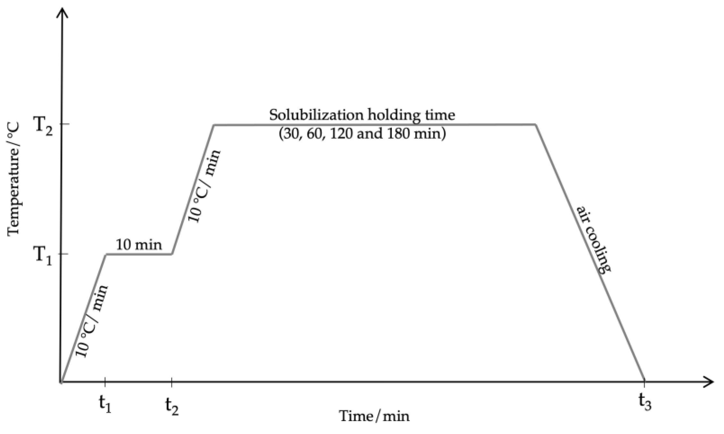
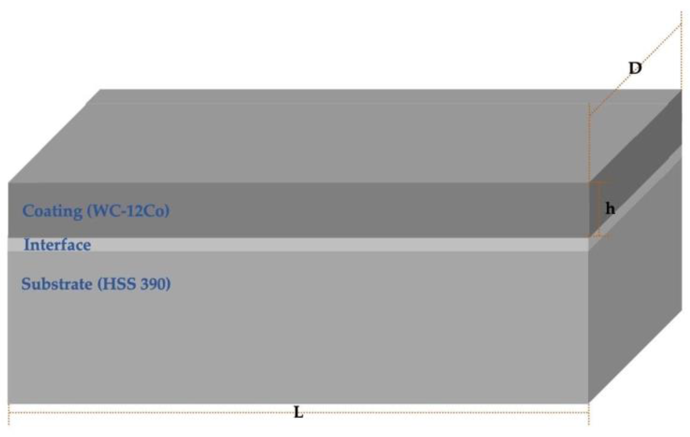
2. Materials and Methods

In this study, a sintered WC-12Co powder was supplied by the GTV (GTV Verschleißschutz GmbH, Luckenbach, Germany) commercial company. As declared by the supplier, the powder was in the form of crushed and non-spherical, inhomogeneously shaped particles (feedstock powder: HVOF-Pulver WC/Co 88/12, −53 + 15 μm). Their chemical composition (wt. %), as directly provided by GTV, is reported in Table 1.
Three layers of WC-12Co powder were deposited by L-DED on 120 mm × 40 mm × 10 mm HSS 390 substrate plates (Figure 1), whose nominal chemical composition is also presented in Table 1. For the deposition, a 6-axis ABB IRB 4600 (ABB, Zurich, Switzerland) robot available at the Birex Competence Center (Bologna, Italy) was employed. The robot was equipped with a coaxial powder nozzle with 6 heads and a laser line source LDF-4500-60 diode of 4.5 kW, which was supplied by a feeding fiber of a 600 μm core diameter, a focusing optics Laserline OTS-5, and a focal length of 300 mm. Argon was used as the carrier and shield gas, operating at flow rates of 7.5 L/min. The cladding optic of the robot was also equipped with a v2.0 NIT CLAMIR camera (CLAMIR, Madrid, Spain), working as a monitoring system for the scanning strategy and melt pool size during the process, thus allowing continuous adjustment of the laser power. The process parameters, collected in Table 2, were selected according to a preliminary study by Liverani et al. [14], who suggested suitable L-DED process parameters for single- and multitrack WC-Co depositions. A scanning strategy known as “ON-OFF” (or as “bi-directional strategy” in the literature [26,27]) was employed. This strategy consists in maintaining the laser turned on only during the deposition while shutting it down during the passage from a single track to the adjacent one. A total of four three-layered WC-12Co depositions were built on two HSS 390 steel plates.
To study the microstructure of the material in the as-built condition but also to investigate the effect of PFHTs on the metallurgical features and mechanical properties of the coating, several specimens of 5 mm × 9 mm × 1 mm were drawn from each deposition by Electrical Discharge Machining (EDM), perpendicularly to the direction of laser deposition, using a FANUC ROBOCUT α-C400iB (FANUC, Oshino, Japan) machine. From each three-layered WC-12Co deposition, one specimen in the as-built condition was then prepared according to the ASTM E3 standard metallographic procedures, starting with grinding by SiC papers from 120 to 2500 grit and final polishing with diamond suspensions from 6 to 1 µm. Thus, the sample was etched with Murakami’s (10 g of K3Fe(CN)6 and 10 g of KOH in 100 mL of H2O) reagent for 5 s and the microstructure was observed by a Leica DMi8A (Leica, Wetzlar, Germany) optical microscope (OM). The optical micrographs were processed by ImageJ image analysis software (Version 1.53e, 2020, National Institutes of Health, Bethesda, MD, USA) to quantify the mean porosity in each deposited layer. A total of fifteen images (area of each image: 2.38 × 1.79 mm2) were analyzed for each sample. More in-depth investigations were finally carried out by a Zeiss EVO MA15 (Carl Zeiss, Jena, Germany) scanning electron microscope equipped with an Oxford Xmax 50 (Oxford Instruments, Abingdon-on-Thames, UK) microprobe for energy-dispersive spectroscopy (SEM/EDS). The SEM images were recorded in secondary electron imaging (SEI-SEM) and back-scattered electron (BSE-SEM) mode.
The identification of phases in the as-built condition was achieved by X-ray diffractometry (XRD) using a D8 Bruker (Bruker, Billerica, MA, USA) X-ray diffractometer with CuKα radiation and a pattern acquisition from 20° to 110° (2θ mode, 0.02° step size, and 1 s/step).
The mean Vickers macrohardness of the sample in the as-built condition was determined under a 10 kgf (HV10) load and a dwelling time of 15 s with an automatic QATM Qness 60 CHD Master + (QATM, Reitbauernweg, Austria) hardness tester according to the UNI EN ISO 6507-1:2018 standard. The mean value was calculated as an average of ten randomly acquired indentations. The mean Vickers macrohardness profile, resulted from five parallel profiles, was determined starting at a distance of about 5300 μm in depth and up to about 500 μm from the surface. For each profile, the first indentation was performed at the interface between the substrate and the first deposited layer, corresponding to the dilution zone, whereas the last indentation was carried out in correspondence with the third deposited layer. Besides that, ten random Vickers microhardness indentations were conducted under a 0.2 kgf (HV0.2) load and a dwelling time of 15 s by the same hardness equipment.
Four different kinds of PFHTs, consisting of a solubilization stage at 400, 500, 600, and 700 °C, respectively, were then conducted in a tubular Lenton LTF 12 (Lenton Furnaces & Ovens, Hope, UK) oven. For each solubilization temperature, four holding times were selected: 30, 60, 120, and 180 min. The solubilization stage was then followed by air cooling to room temperature. For each combination of solubilization temperature and holding time, four specimens were heat-treated; it should be pointed out that one specimen was collected from each three-layered WC-12Co deposition. The general scheme of the heat treatment procedure is depicted in Figure 2, where T2 is the selected solubilization temperature, whereas T1 is half of the selected holding temperature. After heat treatments, the specimens were prepared according to the same abovementioned metallographic procedure. The evolution of the phases with respect to the different applied PFHTs was then monitored by metallurgical investigations carried out with the same optical and scanning electron microscopes. In addition, the macrohardness changes due to the different microstructural features and distribution of phases induced by the heat treatments were determined by the same hardness tester and compared with the mean macrohardness of the as-built specimen assumed as a reference.

3. Results and Discussion

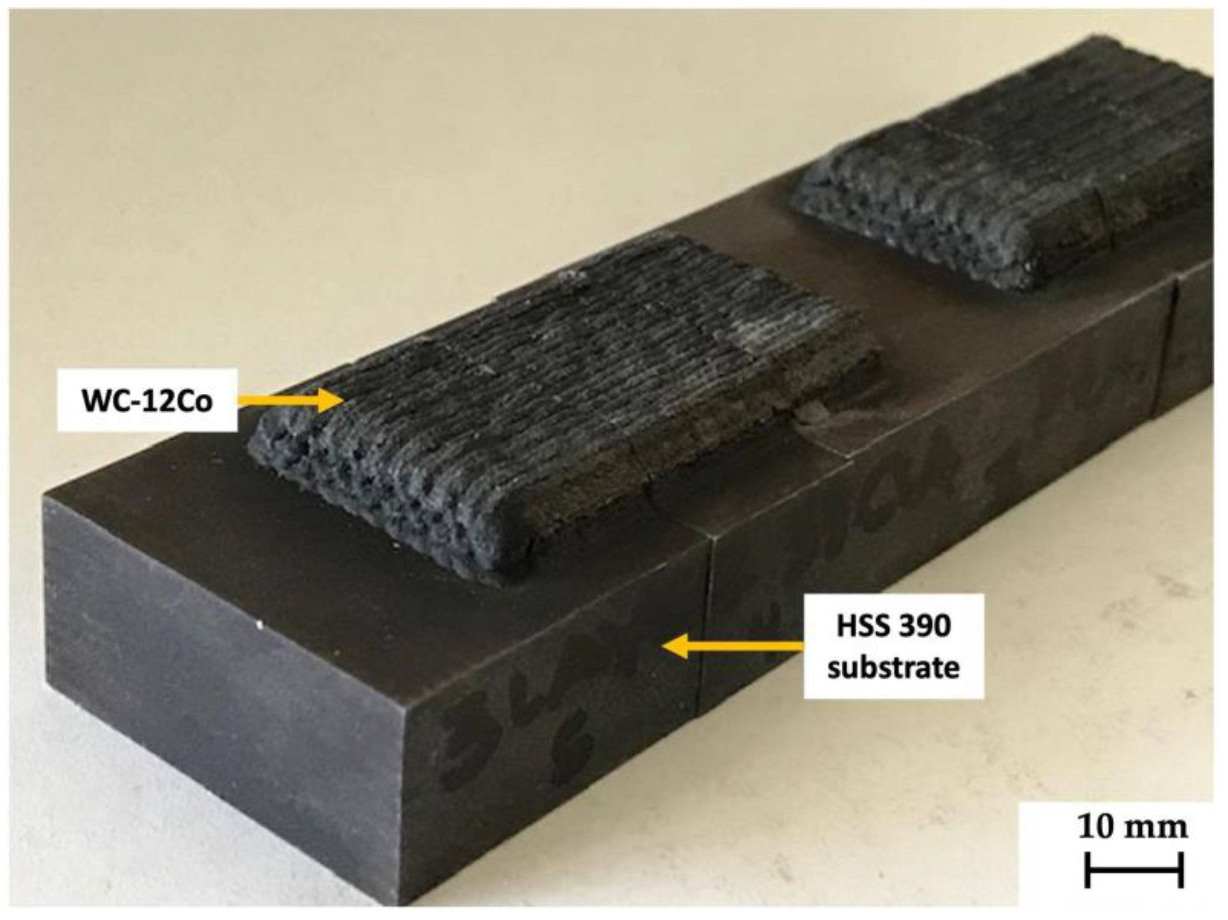
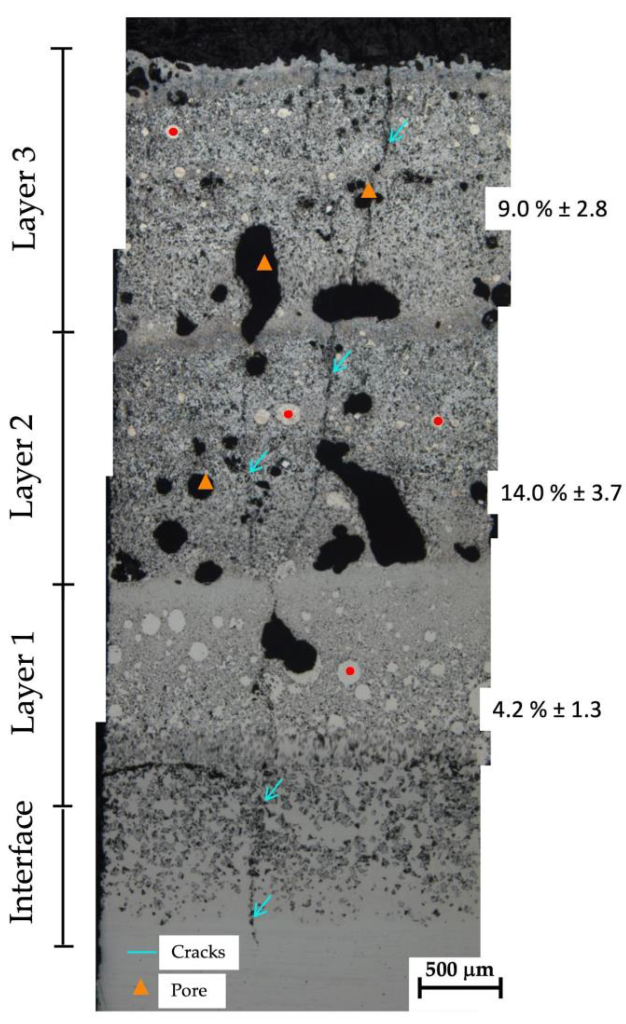
3.1. Macrostructural Investigation of the Sample in the As-Built Condition

Figure 3 shows a collage of optical micrographs of the cross-section (perpendicular to the metal surface) of the sample in the as-built condition. Different zones can be detected according to the deposition of the three layers: an “Interface” zone between the HSS 390 substrate and the first deposition layer (labeled as “Layer 1”), characterized by a dilution process, followed by the presence of two more layers (labeled as “Layer 2” and “Layer 3”). Several pores can be observed throughout the layers (orange triangles in the figure), as well as some cracks (blue arrows in the figure) starting from the substrate and growing up within the deposited layers.
Internal cracks are common defects that appear in AM components, especially in WC-Co materials, usually due to the development of high thermal stresses during the process. Hence, their occurrence must be controlled [13,28,29,30,31,32]. Some research demonstrated that these stresses are generated during solidification [33,34]. Depending on the material properties and the process parameters, when the material is in a mushy state, with continuous and semi-continuous liquid films at the grain boundaries, the restricted resistant area is not able to support the stresses arising from the thermal constraints, thus inducing the generation of cracks [33,34]. In the literature, there are several studies regarding these mechanisms [35,36,37] with both the steep variation of the temperature induced by the AM process and the material properties considered the main key factors in crack generation. When stresses trapped inside the component are suddenly released, cracks emerge on the surface. Once a crack has occurred, it spreads along the molten layer, affecting the soundness of the deposited material.
Concerning porosity, it is known that it affects the hardness of the material due to the presence of voids acting as weakening points in the microstructure [2]. Hence, the evaluation of the material’s porosity is essential for interpreting hardness results. Besides, the measurement of the effective area in a fabricated part is crucial to hardness testing [38]. Effective area, defined as the area used to attain the efficient area of the deposited coating, was calculated as suggested in [38,39]. In the investigated tracks, a mean value of 91.83 ± 2.10% of the effective area was detected. In addition, starting from Layer 1, the mean porosity ± standard deviation in each layer (reported on the right side of Figure 3) was 4.2 ± 1.3%, 14.0 ± 3.7%, and 9.0 ± 2.8%, respectively. It could be seen that the porosity is not homogeneously distributed across the three-layered multitrack depositions. In this regard, the re-heating and partial remelting of Layer 1 during the deposition of Layer 2 probably contributed to the different amounts of porosity in the second layer. Finally, the effect of a different cooling rate during deposition of Layer 3 could also have a significant role in the amount of porosity of this latter track.
The study performed by Zhou et al. [40] proved that a great difference in the thermal expansion behavior among the joining parts has a strong effect on the rising of thermal stresses. Considering that, in the present study, a WC-12Co cermet material was deposited on an HSS 390 steel, following the theoretical model developed in [40] the residual thermal stresses were calculated. Figure 4 depicts the simplified geometry considered in the model; Table 3 collects the thermophysical and mechanical properties, together with the geometrical features assumed for the WC-12Co coating and the HSS 390 steel, which are used to perform the calculations.
According to the theoretical model proposed in [40] and considering the values reported in Table 3, the residual thermal stresses for the HSS 390 steel substrate (σHSS) and for the WC-12Co coating (σWC-12Co) were calculated as follows:
σ SS = 6.9041 × 10 10 / ( 1 2.125   P / V )   Pa ,
σ WC - 12 Co = 1.31187 × 10 10 / ( 1 0.47   V / P )   Pa ,
where V is the scanning speed (mm/s) and P is the laser power (W) (see Table 2). According to Equations (1) and (2), σHSS is equal to 3.22 × 10⁶ Pa, whereas σWC-12Co is equal to −1.31 × 10¹⁰ Pa. The principal stresses are represented by both tensile (positive) stress and compressive (negative) stress. Based on the results and in agreement with [40], the HSS 390 steel and WC-12Co coating suffer from residual tensile and compressive stresses, respectively. The residual compressive stress suffered from the WC-12Co coating, even if calculated by a simplified model, is higher than those previously reported for cermet coatings (e.g., −170 and −920 MPa for WC and Co phases, respectively, at room temperature in [36,42]). Moreover, it should be pointed out that this stress is higher than the compressive strength of the material; so, during the deposition process, the probability of crack initiation in the WC-12Co coating is quite high.
Concerning the microstructure, the sample in the as-built condition showed a high inhomogeneity in the distribution of phases. The high cooling gradients and the thermal cycles induced by the deposition of the three layers promoted a coarse WC grain structure inside the different layers, alternating with WC fine grains along the remelted zones between layers (Figure 3). White rounded areas were also detected across the layers, marked by red dots in Figure 3; these zones are commonly known as residual unmelted WC powder regions and are mainly characterized by a fine dendritic network inside them [14].

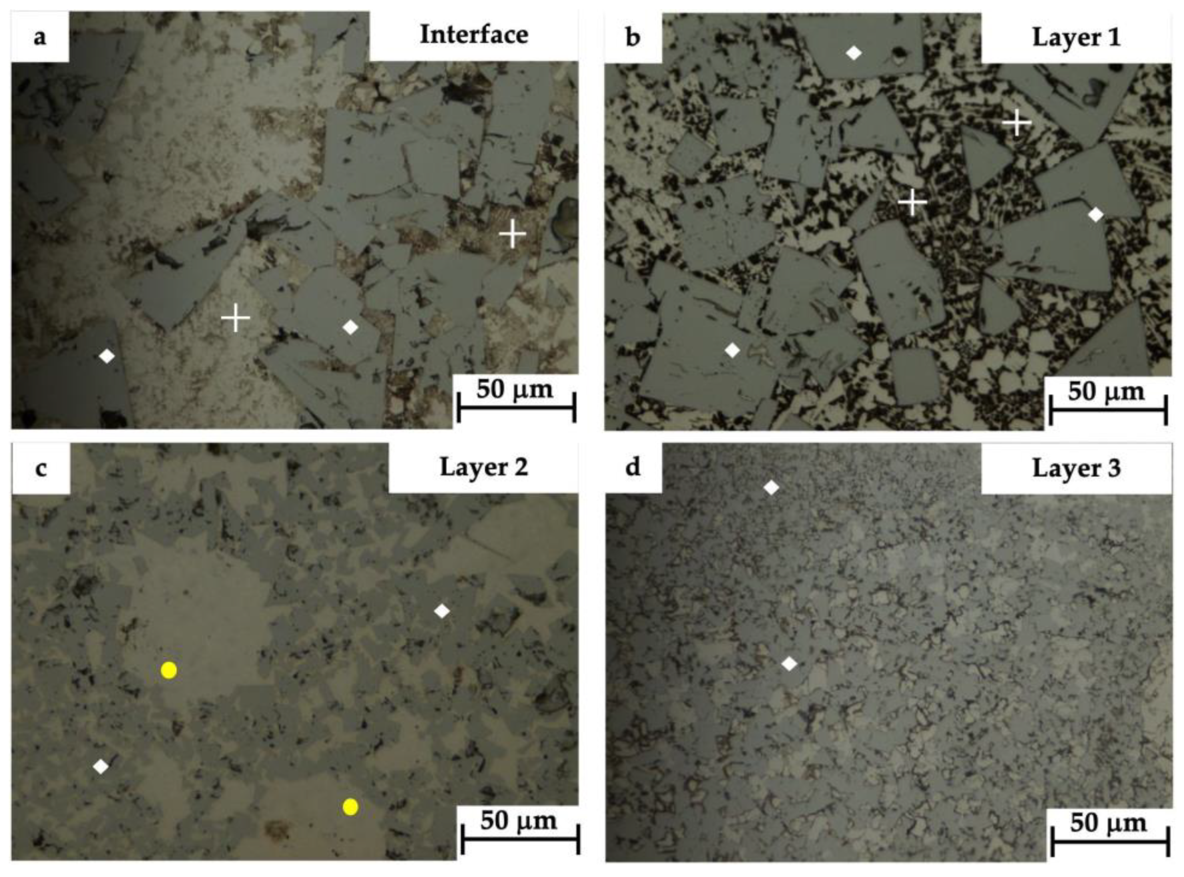
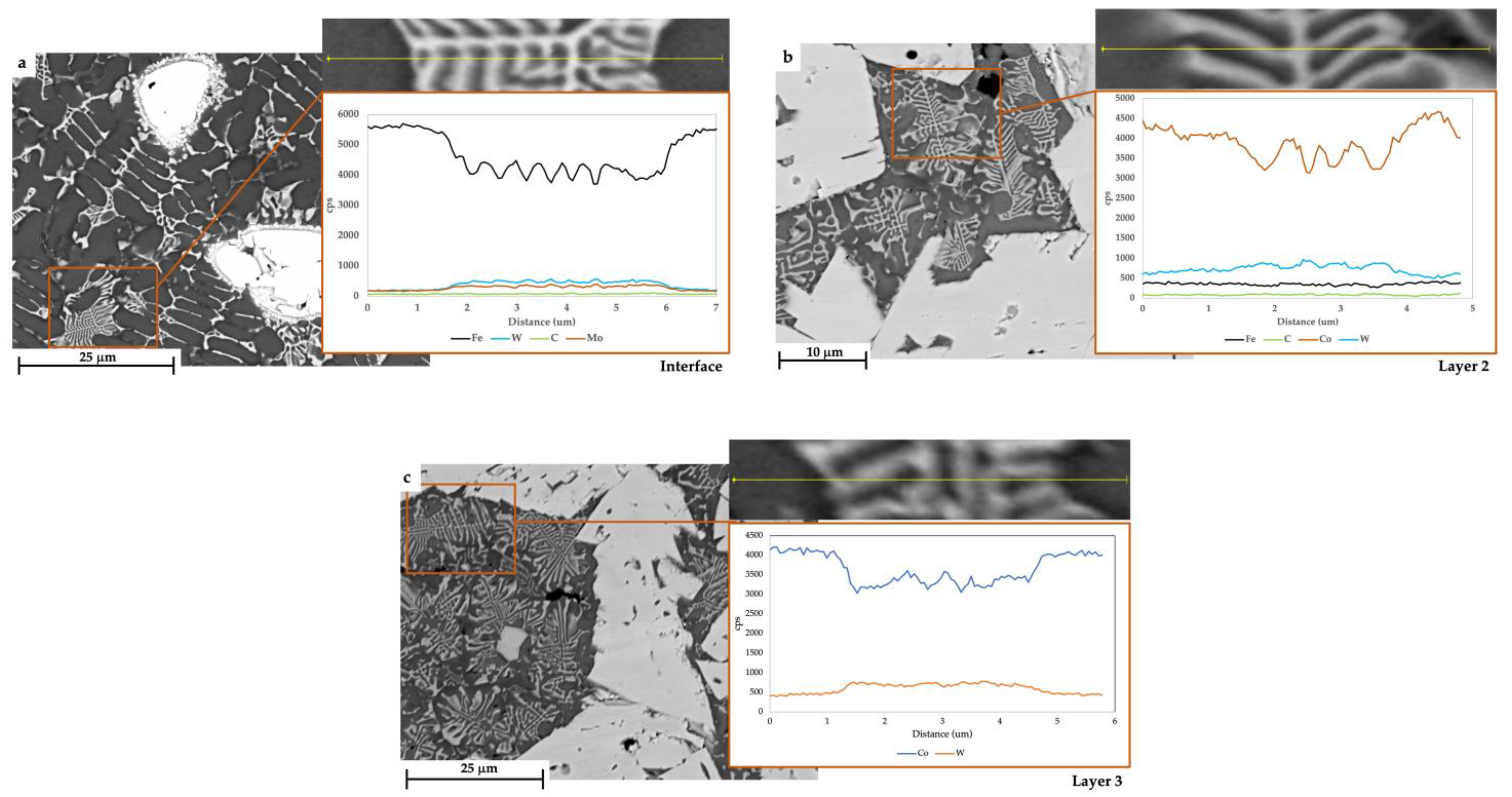
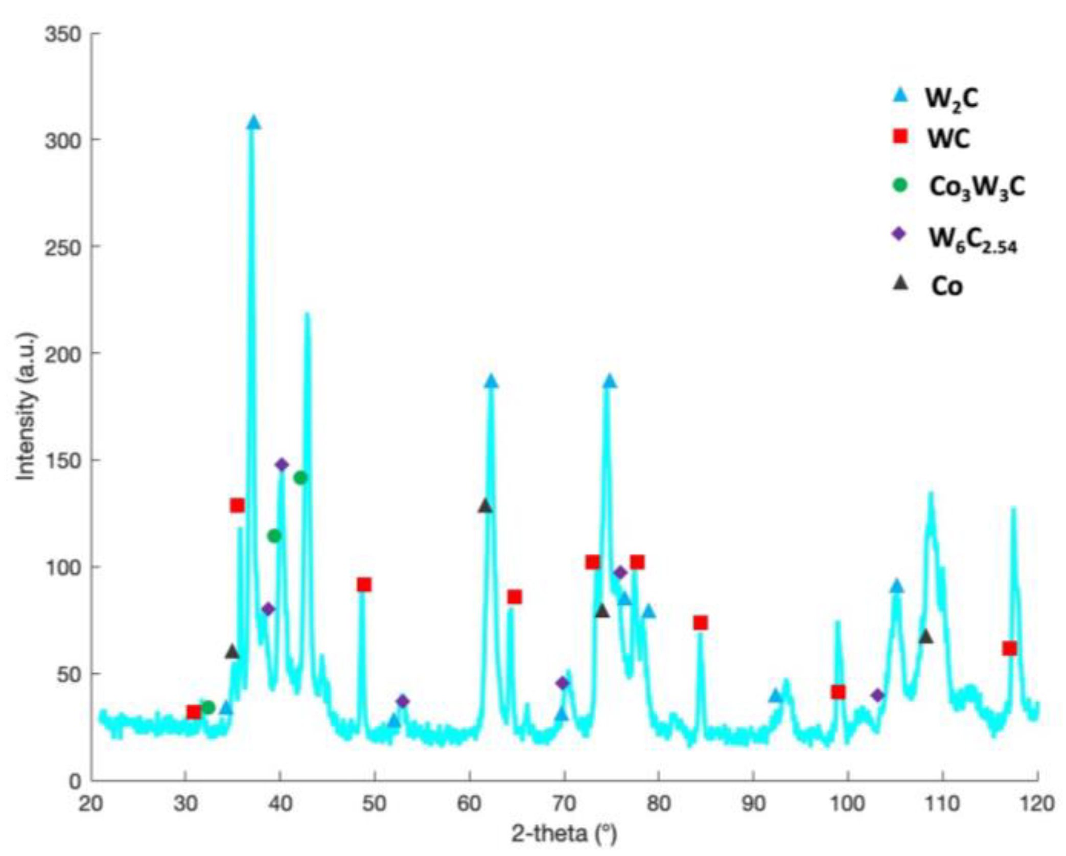
3.2. Microstructural Investigation of the Sample in the As-Built Condition

A deep microstructural investigation of the specimen in the as-built condition was performed to assess the evolution of phases across the three different layers. The OM micrographs of the microstructure observed on the cross-section of the sample in correspondence with the Interface (Figure 5a) and Layer 1 (Figure 5b) show that the joining process that involved the WC-12Co powder and the HSS 390 substrate resulted in polygonal WC grains (white diamonds in the figures) with smooth edges as well as in a fine network of eutectic carbides with herringbone morphology η-phase structure, indicated by white crosses in the figures. In Layer 2 (Figure 5c), the microstructure is quite different and characterized by WC grains (labeled once again by white diamonds) that appear to be of different sizes and distributions. In the same layer, a mixture of fine and coarse polygonal grains embedded in a network of new herringbone carbides and some residual unmelted WC powder regions (yellow dots in Figure 5c) was also detected. It is known that the η-phase structure, which is a ternary compound usually composed of W, Co or Fe, and C, can exist in two main types of carbide, either as a M6C-type carbide ranging from M3W3C to Co32W28C and Co2W4C or as a M12C-type carbide (e.g., Co6W6C) if a C deficiency occurs during the process (for both types of carbides, M = (Fe, Co)) [3,43,44]. The presence of this latter type of carbide is often regarded as undesirable since it degrades the mechanical behavior of the cermet [45,46,47,48]. Hence, it is important to maintain the M12C-type carbide at a lower level and size [49]. In this work, the temperature suffered from the powder during the L-DED process and exceeded the melting point of Co (1495 °C), thus resulting in the dissolution of WC into the Co phase and leading to a C loss. This loss of C caused the transformation of WC carbides into the η-phase, as similarly reported in [18,50].
Finally, Layer 3 is mainly characterized by fine WC grains, even if coarse polygonal WC grains are also visible (white diamonds in Figure 5d).
The Interface, Layer 1, Layer 2, and Layer 3 were then investigated in more detail by SEM/EDS. The SEM micrographs depicted in Figure 6 show WC grains with different sizes and morphology across the different regions. At the Interface and inside Layer 1, rounded particles mixed with some polygonal ones can be observed (Figure 6a,b) together with a high quantity of herringbone eutectic carbides (Figure 6c,d). As already mentioned in Section 3.2, the chemical composition of η-phase structures can be slightly different according to the process conditions [5,36,37]. From the EDS data collected in Table 4, it can be inferred that the η-phase structures at the Interface and inside Layer 1 contain high quantities of Fe, W, Cr, and low amounts of Co (sites A and C). For increasing distances from the substrate (i.e., in Layer 2), lower contents of Fe and higher percentages of Co were detected (site F). In Layer 3, only W and Co were detected (sites G and H). To confirm these experimental findings, in Figure 7, the EDS profile-line analysis (yellow segment through a η-phase structure detected across the regions labeled in Figure 4) of Fe, W, C, and Mo at the Interface, in Layer 2, and in Layer 3, respectively, are reported. The semi-quantitative analysis demonstrated that the composition of the η-phase structures changes with the increase in distance from the substrate. High quantities of Fe and Mo were identified at the Interface between the substrate and Layer 1 due to the dilution occurring during the deposition. In Layer 2, a lower content of Fe and no Mo were detected, whereas in Layer 3, only W and Co were found.
The semi-quantitative analysis of random WC carbides of different sizes and morphology was also conducted by EDS; data are collected in Table 4 (sites B, D, and E). The highest amount of Co was identified in site D, while the highest percentage of W was detected in site E. Concerning the unmelted WC residual powder regions, their semi-quantitative chemical composition and their peculiar rounded shape are proved by the SEM/EDS back-scattered electron image and maps of the elemental distribution of Figure 8.
To deepen the knowledge of the phases in the sample in the as-built condition, X-ray diffraction analysis was performed and the spectrum is reported in Figure 9. In the analyzed specimen, both the WC and W2C, and the non-stoichiometric tungsten carbide W6C2.54 peaks, were identified. Moreover, Co peaks as well as those related to the presence of M6C carbides with high contents of Co (i.e., Co3W3C) were recognized. As confirmed by the literature [49,51], during deposition, the WC-Co cemented carbide undergoes WC decomposition at high temperatures. Usually, during this decomposition, W mainly combines with C to form the following carbides: WC, also known as δ-WC, WC0.5 (β-W2C together with other two polymorphs: α-W2C and γ-W2C), and γ-WC1-x, which are stable at a specific temperature.

3.3. Hardness Behavior of the Sample in the As-Built Condition

Figure 10 depicts the mean Vickers macrohardness profile (HV10) determined in the sample in the as-built condition together with the OM micrographs of representative indentations. As specified in Section 2, each histogram in the graph is the mean value of five indentations, while the error bars represent the standard deviation. The mean Vickers macrohardness profile shows a first sharp increase up to 1010 ± 38 HV10 (light blue label in the graph), where the microstructure is constituted to a major extent by fine WC carbides (i.e., at a distance of 1800 μm from the interface). This value is higher than 849 ± 78 HV10 (green label in the graph), registered in the zone where an inhomogeneous distribution of coarse WC particles is present (i.e., at a distance of 3000 μm from the interface). Moreover, across the three-layer depositions, the mean macrohardness does not settle on an almost constant value but undergoes significant variations from one layer to another. In general, the mean Vickers macrohardness values are lower than those previously reported for these types of cermets [18]. To verify this, Vickers microhardness measurements were also performed. Different values were detected in relation to the indented zone. As an example, the microhardness is very low and equal to 641 HV0.2 at the regions containing η-phase structures, while at the regions filled with fine and coarse WC particles, the microhardness increases up to 1663 HV0.2. It is understood that the localization of indentation has a strong influence on the local hardness value and, consequently, on the hardness mean values and standard deviations.

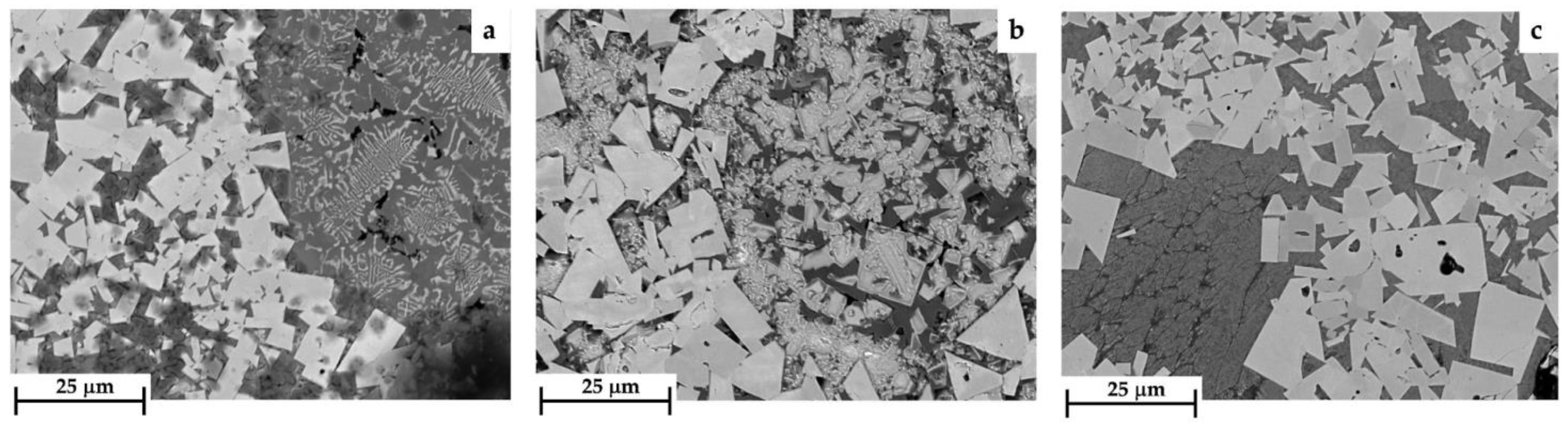
3.4. Microstructural Analysis of Samples in PFHT Conditions

In the PFHT conditions, the samples showed the presence of some cracks across the thickness of the coating. As an example, the blue arrows in Figure 11 report a crack path in the sample heat-treated at 400 °C for 180 min. The origin of the crack is almost always inside the substrate, just above the interface zone. This is in agreement with the possible generation of thermal stresses due to the difference in thermal expansion between the cermet and the metallic substrate, especially during the air cooling from the solubilization temperature. Then, the crack crosses at least the first deposition layer, following a path that fractures the WC polygonal carbides. Indeed, it is known that the WC carbides are prone to cracking due to their intrinsic hardness and brittleness [52].
The proposed PFHTs induced some microstructural changes, especially as concerns the Co matrix and the distribution of the η-phase structures inside it. The existing WC carbides did not undergo noteworthy dimensional changes. Nevertheless, reasonable morphological differences were detected if compared to the as-built condition.
Figure 12 shows a comparison between the microstructure of samples heat-treated for lower times and temperatures (e.g., at 500 °C for 30 min) and for higher times and temperatures (e.g., at 700 °C for 180 min) at the Interface. Most of all, it is worth noting that, while in the as-built condition the WC carbides appeared rounded with shattered edges, after heat treatment the newly formed carbides exhibit a polygonal geometry with well-defined boundaries, as already mentioned in [16,24]. Additionally, the presence of branched eutectic structures within this region has significantly decreased, being replaced by dense spongy agglomerates (highlighted in orange in Figure 12a). However, the thickness of the dendrites of the eutectic carbides appears to increase with longer treatment times and higher temperatures (Figure 12b).
The BSE-SEM micrographs in Figure 13 report a comparison between some representative herringbone η-phase structures characterized by different morphology, according to the PFHT parameters employed in this study. For solubilization temperatures in the range of 400–600 °C, the higher the dwelling time, the higher the size of the η-phase. Specifically, when the solubilization temperature is in the range of 500–600 °C, the distribution and the quantity of this phase are regular, without any coarsening effect for dwelling times up to 120 min (Figure 13a). When the heat treatment is performed at 700 °C, the highest quantity of coarse η-phase is clearly visible (Figure 13b).
For all heat-treated samples, only slight variations in the semi-quantitative chemical composition of phases in Layer 1 and Layer 2 were detected, with respect to the chemical features of phases in the same zones of the sample in the as-built condition. Figure 14 depicts the BSE-SEM images of the cross-section of the sample heat-treated at 500 °C for 30 min in correspondence with Layer 1 together with an indication of the sites subjected to semi-quantitative EDS analysis (letters from A to D). The EDS data are collected in Table 5. The amount of Co in the herringbone eutectic carbides of the heat-treated sample is slightly higher than that registered in the η-phase structure of the sample in the as-built condition (sites A–D in Table 5 in comparison with site C in Table 4). In the sample in the as-built condition, detectable amounts of Co were also found only at the boundary between Layer 1 and Layer 2. Moreover, throughout the thickness of Layer 1, some Co-rich regions admixed with coarse WC carbides were identified, proving the homogenization effect induced by the solubilization treatment.
In some regions, especially in samples heat-treated for the longest dwelling times and at high solubilization temperatures (500, 600, and 700 °C), the coarse WC grains seem to be smothered and agglomerated onto each other (Figure 15), even if some irregularities can be detected on their polished surface. More specifically, in samples heat-treated at 500 and 600 °C for the longest dwelling time, carbides with a particular morphology were observed, whose edges appear strongly jagged (orange arrows in the figure). Conversely, in the as-built condition, only regular and polygonal WC grains were observed, also characterized by a more homogeneous surface.
Concerning Layer 2, irrespective of heat treatment parameters, no longer rounded, dense, and irregular agglomerates, which instead characterized the sample in the as-built condition, were observed. Polygonal WC grains were detected mainly in samples treated at lower solubilization temperatures for dwelling times of 30 and 60 min (Figure 16a). The observed microstructure is related to the interval of time during which the material was subjected to the remelting process. This layer suffered a combination of deposition and remelting of the powder, having a higher cooling rate, which promotes less dissolution and growth of the WC particles, leaving a high quantity of residual WC areas. Moreover, a change in the morphology of the herringbone eutectic carbides was observed with the increasing solubilization temperature (Figure 16b).
Finally, in Layer 3 of the samples heat-treated at the higher temperatures and for the highest dwelling times, the η-phase structures seemed more compact (Figure 16c).
In summary, the post-fabrication heat treatments induce only minimal changes in the chemical composition of phases. Nevertheless, the local distribution of η-phase structures as well as the size and morphology of WC grains is altered, as proved by our SEM/EDS analysis. In [24], it was found that the higher the heat treatment temperature, the greater the extent of WC particle dissolution. In addition, the WC dissolution diffuses into the metallic matrix and forms another carbide phase and new eutectic phases. In the present study, it was confirmed that the samples heat-treated at the higher temperatures (between 500–600 °C) and for the higher holding times (between 120 and 180 min) are characterized by different η-phase structures and WC carbide distributions, thus influencing their hardness behavior.

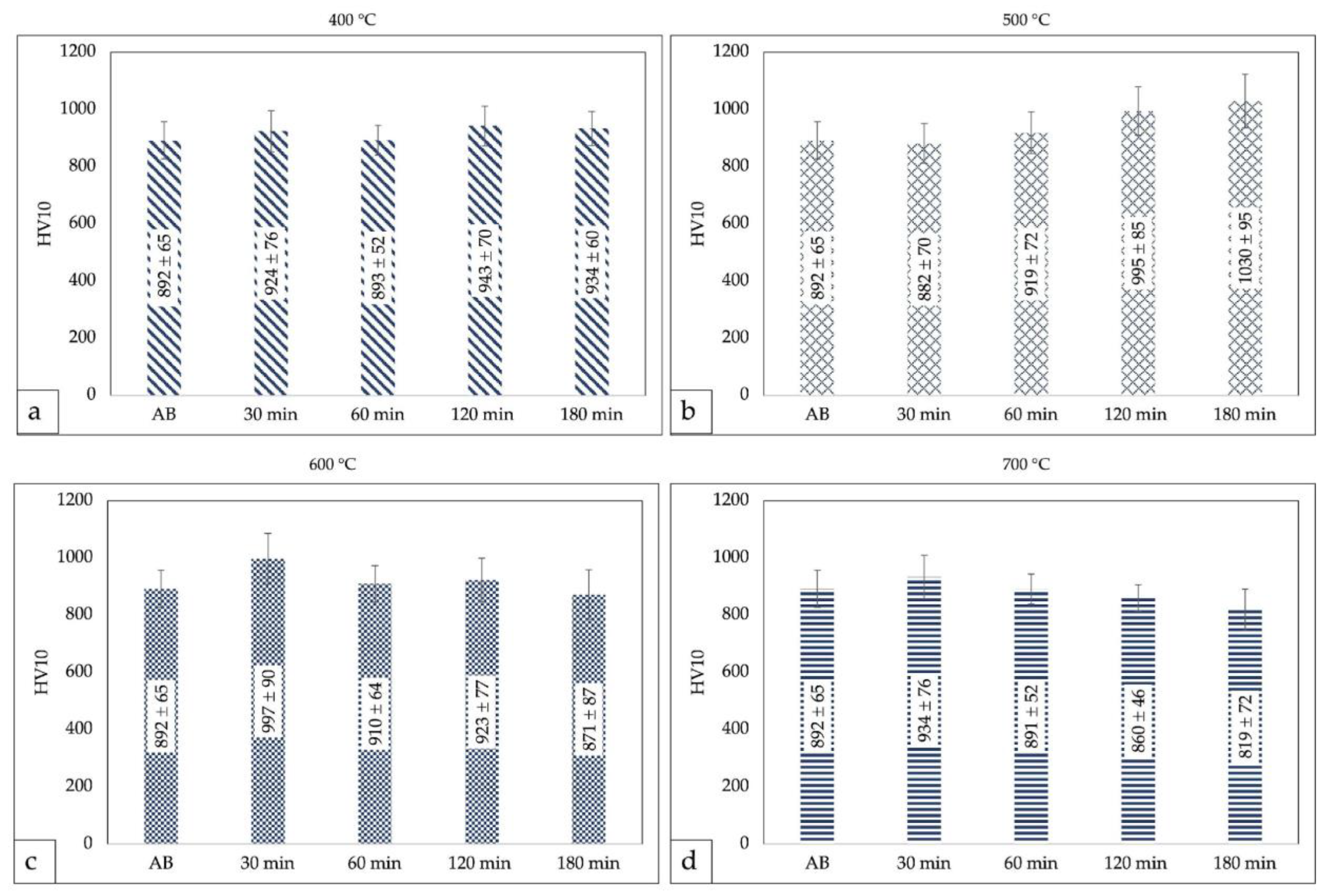
3.5. Hardness Properties of Samples in PFHT Conditions

The hardness properties of the coating after the PFHTs performed at different temperatures and dwelling times are collected in the bar chart of Figure 17. The mean macrohardness values (HV10) are reported as bars, whereas the error bars represent standard deviations.
It should be pointed out that, due to the high standard deviations of the results, no specific trends of macrohardness can be defined for the different solubilization temperatures and dwelling times (Figure 17a–d). The homogenization of the microstructure expected with the PFHTs was not so effective in increasing the mean macrohardness and reducing, at the same time, the scatter of data. Only the samples heat-treated at 500 °C for a dwelling time of 120 min upwards were able to slightly exceed the macrohardness of the material in the as-built condition (Figure 17b), with the highest mean macrohardness values being obtained for a solubilization treatment performed at 500 °C for a dwelling time of 180 min. This trend could probably be due to the occurrence of two contrasting phenomena. As reported by Yuan et al. [53], the first one is the relaxation of residual thermal stresses, particularly of compressive stresses, which determines a decrease in hardness. The second one is the evolution of hardening phases, which probably requires a longer time to be quite effective [48]. In the present study, it was observed that this second phenomenon started to be predominant only after 120 min of holding time. Solubilization temperatures higher than 500 °C (i.e., 600 °C and 700 °C) seemed to be ineffective in increasing the macrohardness of the material. For these latter investigated temperatures, the mean macrohardness drops drastically just after 30 min of dwelling time and continues to decrease as the holding time increases (Figure 17c,d). At these heat treatment temperatures, the relaxation of the residual thermal stresses may not be balanced by an effective hardening effect.
Considering the substantial difference in the cooling speed adopted in this work with respect to classical annealing, the mean Vickers macrohardness values of heat-treated samples are different from those previously reported for annealing treatments carried out in the same range of temperatures [54,55]. According to the literature, the annealing treatments for WC-Co cermets are usually performed for 180 min and temperatures within the range of 500–600 °C [6,56]. The same treatment performed at 700 °C showed a drop in hardness independently of the dwelling times [24]. In the present case, the mean Vickers macrohardness is in the range between 850 HV10 and 1000 HV10, relatively higher than the 55–65 HRC (corresponding to 600–840 HV10) reported in [25] but lower than the 1300–1800 HV0.3 reported in [6].

4. Conclusions

In this work, WC-12Co L-DED additively manufactured samples were subjected to different post-fabrication heat treatments. An in-depth analysis of the microstructure and mechanical properties of the coating was performed to evaluate the changes induced by the different PFHT conditions. Based on the results, the following conclusions can be drawn:
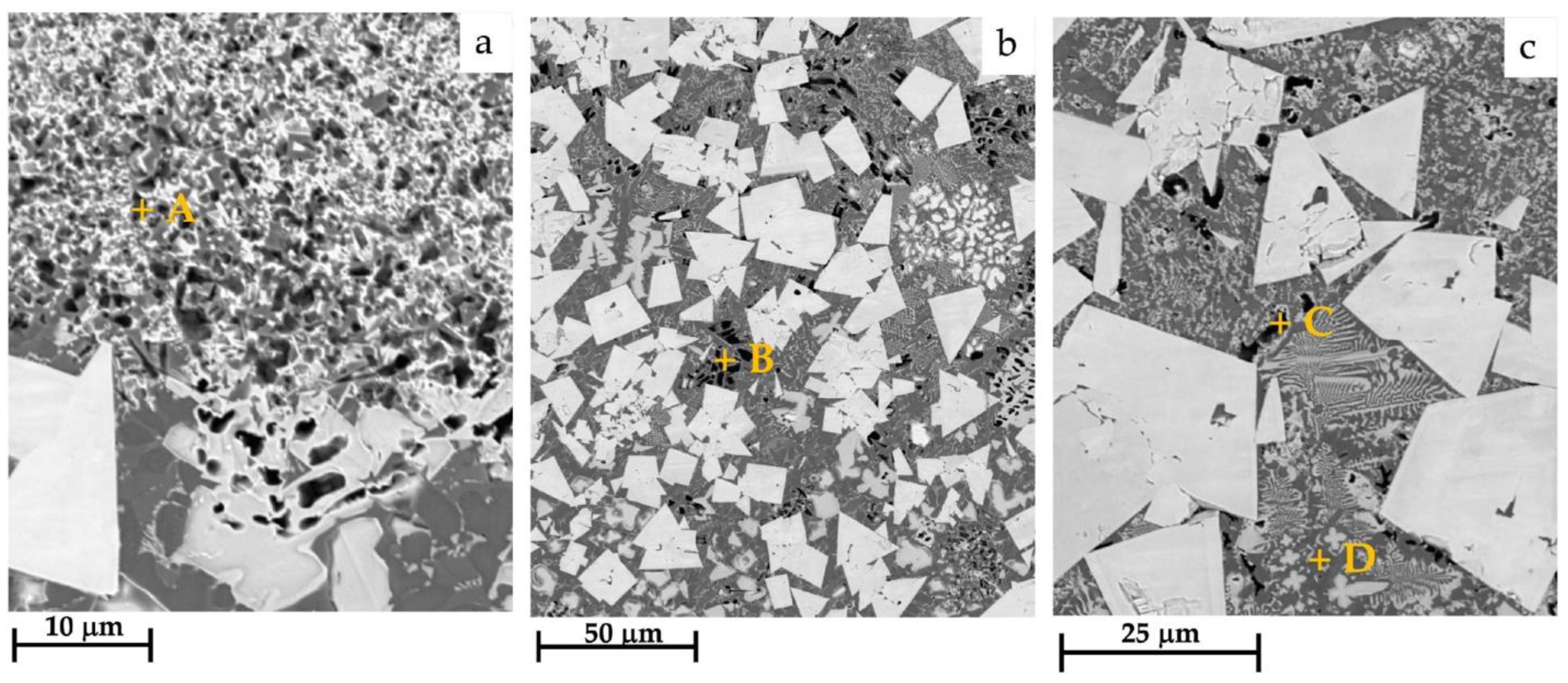
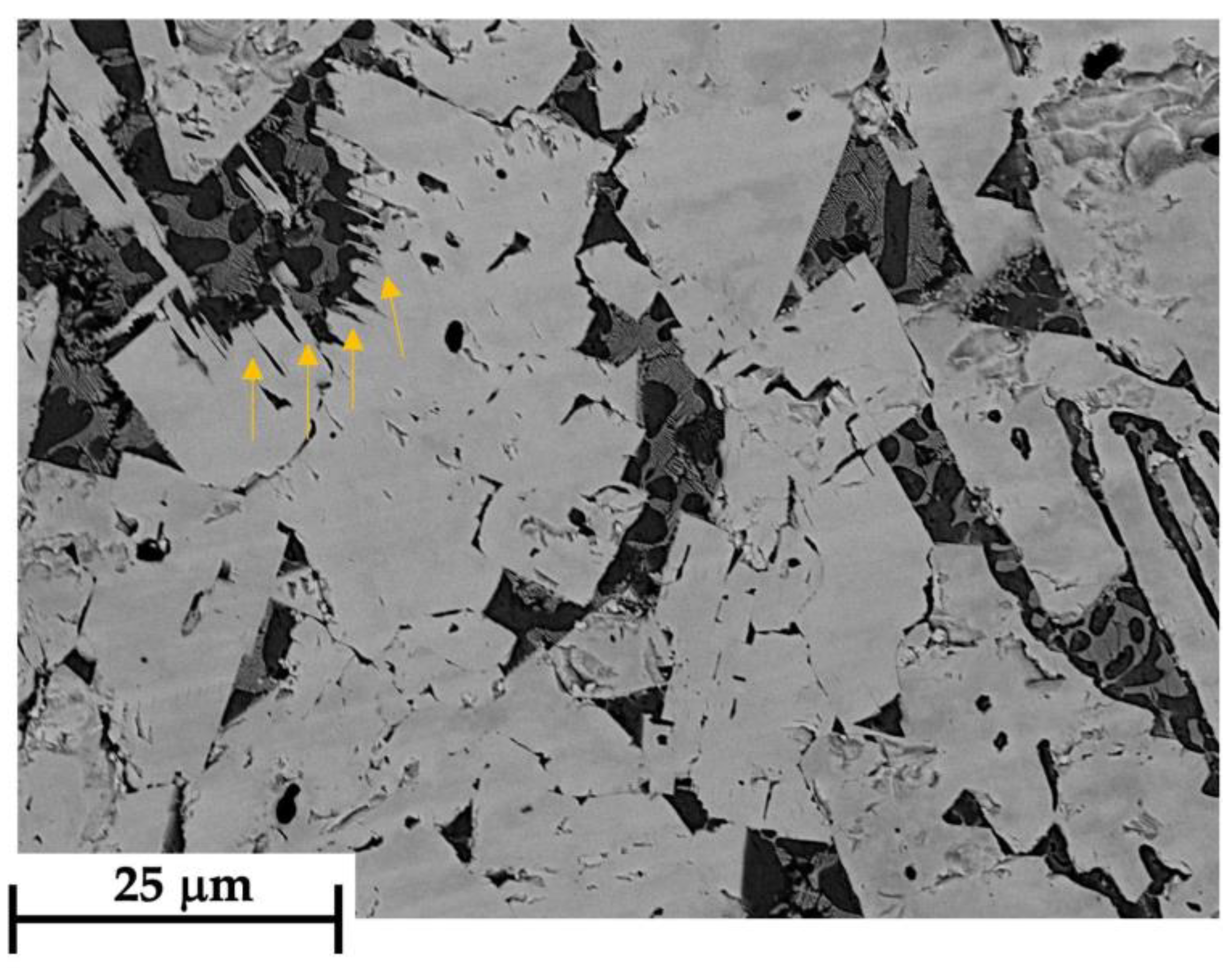
  • High microstructural heterogeneity in terms of WC particles, η-phase structures, and Co distribution was observed in the sample in the as-built condition.
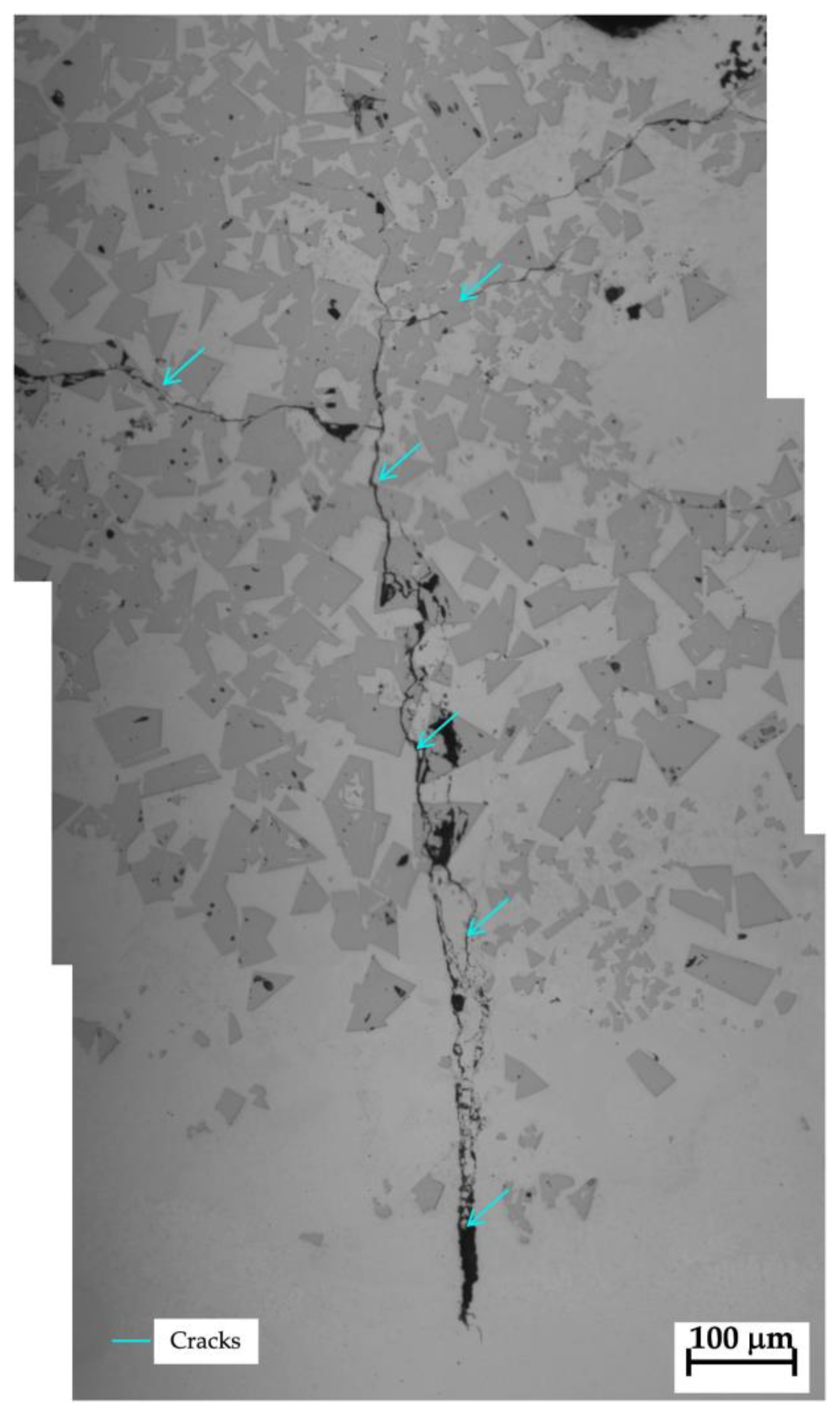
  • Some cracking defects were observed in the samples, irrespective of the heat treatment conditions. In this regard, it is confirmed that the difference in thermophysical properties of the substrate and the coating has a strong influence on crack propagation.
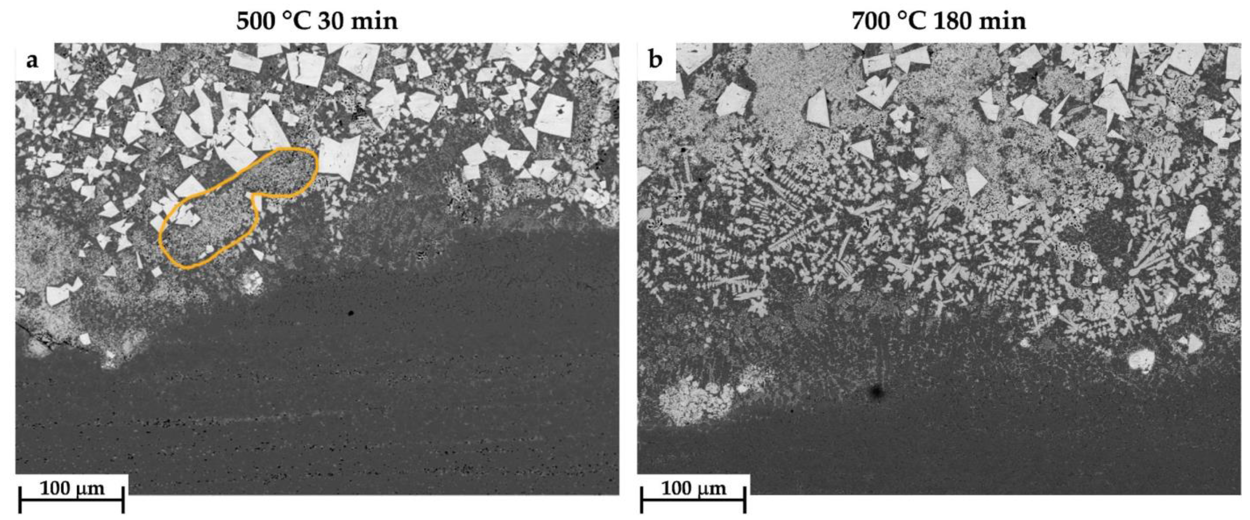
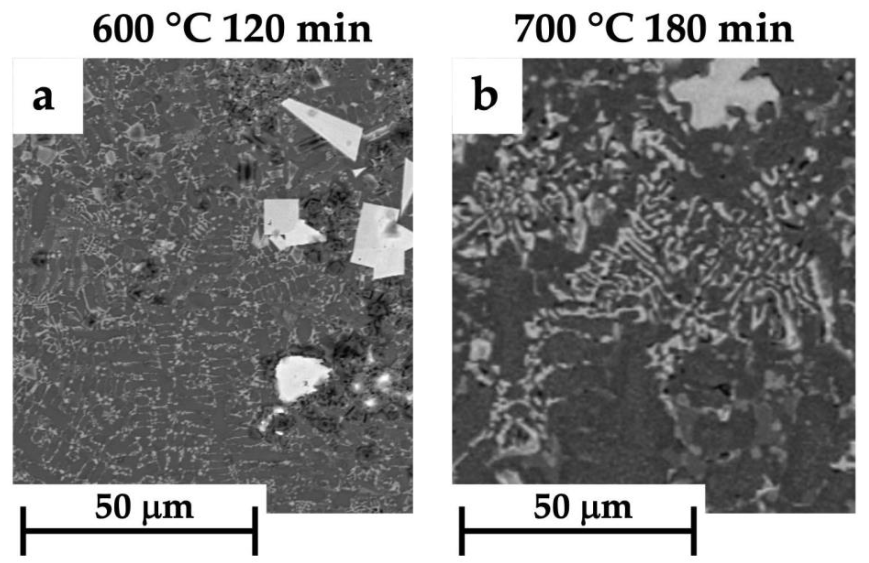
  • For all heat-treated samples, the OM and SEM/EDS analysis of the microstructure demonstrated the occurrence of some microstructural changes during the post-fabricated heat treatment procedures. Especially, the local distribution of η-phase structures, and the size and distribution of the WC grains, were altered by the PFHTs.
  • Considering PFHTs performed at 500 °C for dwelling times in the range of 120–180 min, the mean Vickers macrohardness of heat-treated samples was slightly higher than that of the as-built sample, with the highest mean macrohardness values being obtained for a solubilization treatment performed for a dwelling time of 180 min.
  • Further optimization of the post-fabricated heat treatment parameters needs to be performed to guarantee proper use of the WC-12Co cermet coating fabricated by the L-DED additive manufacturing technique.

Author Contributions

Data curation, C.M.; formal analysis, C.M. and M.M.; funding acquisition, M.M.; investigation, C.M. and M.M.; methodology, C.M., M.M., A.F., and C.S.; resources, M.M.; supervision, M.M.; validation, C.M. and M.M.; visualization, C.M. and M.M.; writing—original draft, C.M.; writing—review and editing, M.M., A.F., and C.S. All authors have read and agreed to the published version of the manuscript.

Funding

This work was supported by the BiRex Corporation (Project AN-MEC—L’Additive Manufacturing nella filiera produttiva dell’industria meccanica: dallo sviluppo del processo alla definizione del business model per la produzione di nuovi componenti”, CUP C41J20000030008).

Institutional Review Board Statement

Not applicable.

Informed Consent Statement

Not applicable.

Data Availability Statement

The authors confirm that the processed data supporting the findings of this study are available within the article. The raw data not explicitly reported in the article are available on request.

Acknowledgments

The authors wish to acknowledge Leonardo Zambello for his valuable help in the research of the present investigation and Alessandro Fortunato for having provided the samples analyzed in the present research.

Conflicts of Interest

The authors declare no conflict of interest.

References

  1. Yang, Y.; Zhang, C.; Wang, D.; Nie, L.; Wellmann, D.; Tian, Y. Additive Manufacturing of WC-Co Hardmetals: A Review. Int. J. Adv. Manuf. Technol. 2020, 108, 1653–1673. [Google Scholar] [CrossRef]
  2. Aramian, A.; Razavi, S.M.J.; Sadeghian, Z.; Berto, F. A Review of Additive Manufacturing of Cermets. Addit. Manuf. 2020, 33, 101130. [Google Scholar] [CrossRef]
  3. Liu, C. Alternative Binder Phases for WC Cemented Carbides. Available online: https://www.semanticscholar.org/paper/Alternative-binder-phases-for-WC-cemented-carbides-Liu/89999edcb533faea1869eb3f876a4bb5b2c79e75.
  4. He, H.T.; Fang, J.X.; Wang, J.X.; Sun, T.; Yang, Z.; Ma, B.; Chen, H.T.; Wen, M. Carbide-Reinforced Re0.1Hf0.25NbTaW0.4 Refractory High-Entropy Alloy with Excellent Room and Elevated Temperature Mechanical Properties. Int. J. Refract. Met. Hard Mater. 2023, 116, 106349. [Google Scholar] [CrossRef]
  5. Fortunato, A.; Valli, G.; Liverani, E.; Ascari, A. Additive Manufacturing of WC-Co Cutting Tools for Gear Production. Lasers Manuf. Mater. Process. 2019, 6, 247–262. [Google Scholar] [CrossRef]
  6. Joseph, A. Additive Manufacturing of Novel Cemented Carbides with Self Lubrificating Properties. Master’s Thesis, York University, Toronto, Ontario, 2019. [Google Scholar]
  7. Ma, G.; He, P.; Wang, H.; Tian, H.; Zhou, L.; Yong, Q.; Liu, M.; Zhao, H.; He, D. Promoting Bonding Strength between Internal Al-Si Based Gradient Coating and Aluminum Alloy Cylinder Bore by Forming Homo-Epitaxial Growth Interface. Mater. Des. 2023, 227, 111764. [Google Scholar] [CrossRef]
  8. ASTM F2792-12; Standard Terminology for Additive Manufacturing Technologies. ASTM International: West Conshohocken, PA, USA, 2012.
  9. Herzog, D.; Seyda, V.; Wycisk, E.; Emmelmann, C. Additive Manufacturing of Metals. Acta Mater. 2016, 117, 371–392. [Google Scholar] [CrossRef]
  10. Aliakbari, M. Additive Manufacturing: State-of-the-Art, Capabilities, and Sample Applications with Cost Analysis. 2012. Available online: https://www.semanticscholar.org/paper/Additive-Manufacturing%3A-State-of-the-Art%2C-and-with-Aliakbari/25d838489048379a3ededacf1ce1a716451b8529 (accessed on 10 August 2023).
  11. ISO/ASTM 52900; Additive Manufacturing—General Principles. International Standard; ASTM: West Conshehoken, PL, USA, 2015; pp. 1–28. [Google Scholar]
  12. Wang, L.; Wu, T.; Wang, D.; Liang, Z.; Yang, X.; Peng, Z.; Liu, Y.; Liang, Y.; Zeng, Z.; Oliveira, J.P. A Novel Heterogeneous Multi-Wire Indirect Arc Directed Energy Deposition for in-Situ Synthesis Al-Zn-Mg-Cu Alloy: Process, Microstructure and Mechanical Properties. Addit. Manuf. 2023, 72, 103639. [Google Scholar] [CrossRef]
  13. Campanelli, S.L.; Contuzzi, N.; Posa, P.; Angelastro, A. Printability and Microstructure of Selective Laser Melting of WC/Co/Cr Powder. Materials 2019, 12, 2397. [Google Scholar] [CrossRef]
  14. Liverani, E.; Ascari, A.; Fortunato, A. Multilayered WC–Co Coatings by Direct Energy Deposition-Based Cladding: Effect of Laser Remelting on Interface Defects. Surf. Coat Technol. 2023, 464, 129556. [Google Scholar] [CrossRef]
  15. Fries, S.; Genilke, S.; Wilms, M.B.; Seimann, M.; Weisheit, A.; Kaletsch, A.; Bergs, T.; Schleifenbaum, J.H.; Broeckmann, C. Laser-Based Additive Manufacturing of WC–Co with High-Temperature Powder Bed Preheating. Steel Res. Int. 2020, 91, 1900511. [Google Scholar] [CrossRef]
  16. Zhou, X.; Liu, H.; Zhang, J.; Ji, J.; Zhao, W.; Zhang, Z.; Wang, Q.; Xue, Y. Effect of the Heat Treatment on the Microstructure and Performance of High-Velocity Air-Fuel Sprayed WC-10Co4Cr Coatings. Mater. Tehnol. 2021, 55, 885–894. [Google Scholar] [CrossRef]
  17. Son, S.; Park, J.M.; Park, S.H.; Yu, J.H.; Kwon, H.; Kim, H.S. Correlation between Microstructural Heterogeneity and Mechanical Properties of WC-Co Composite Additively Manufactured by Selective Laser Melting. Mater. Lett. 2021, 293, 129683. [Google Scholar] [CrossRef]
  18. Hu, M.; Tang, J.C.; Chen, X.G.; Ye, N.; Zhao, X.Y.; Xu, M. miao Microstructure and Properties of WC-12Co Composite Coatings Prepared by Laser Cladding. Trans. Nonferrous Met. Soc. China 2020, 30, 1017–1030. [Google Scholar] [CrossRef]
  19. Jonsson, H. Studies of the Binder Phase in Wc-Co Cemented Carbides Heat Treated at 950 °C. Fuer. Pulvemetallurg. 1975, 23, 37–55. [Google Scholar]
  20. Jonsson, H. Studies of the Binder Phase in Wc-Co Cemented Carbides Heat-Treated at 650 °C. Powder Metall. 1972, 15, 1–10. [Google Scholar] [CrossRef]
  21. Andrén, H.-O. Microstructure Development during Sintering and Heat-Treatment of Cemented Carbides and Cermets. Mater. Chem. Phys. 2001, 67, 209–213. [Google Scholar] [CrossRef]
  22. Gu, L.; Huang, J.; Tang, Y.; Xie, C.; Gao, S. Influence of Different Post Treatments on Microstructure and Properties of WC-Co Cemented Carbides. J. Alloys Compd. 2015, 620, 116–119. [Google Scholar] [CrossRef]
  23. Chen, C.; Du, C.; Pan, Q.; Chen, Q. Effect of Post-Heat Treatment on the Microstructure and Mechanical Properties of Laser-Deposited WxC + Ni-Based Composite Thin Walls. J. Mater. Eng. Perform. 2021, 30, 423–433. [Google Scholar] [CrossRef] [PubMed]
  24. Mazouzi, A.; Djerdjare, B.; Triaa, S.; Rezzoug, A.; Cheniti, B.; Aouadi, S.M. Effect of Annealing Temperature on the Microstructure Evolution, Mechanical and Wear Behavior of NiCr-WC-Co HVOF-Sprayed Coatings. J. Mater. Res. 2020, 35, 2798–2807. [Google Scholar] [CrossRef]
  25. Kumar, S. Process Chain Development for Additive Manufacturing of Cemented Carbide. J. Manuf. Process. 2018, 34, 121–130. [Google Scholar] [CrossRef]
  26. Jia, H.; Sun, H.; Wang, H.; Wu, Y.; Wang, H. Scanning Strategy in Selective Laser Melting (SLM): A Review. Int. J. Adv. Manuf. Technol. 2021, 113, 2413–2435. [Google Scholar] [CrossRef]
  27. Liu, W.-W.; Saleheen, K.M.; Tang, Z.; Wang, H.; Al-Hammadi, G.; Abdelrahman, A.; Yongxin, Z.; Hua, S.-G.; Wang, F.-T. Review on Scanning Pattern Evaluation in Laser-Based Additive Manufacturing. Opt. Eng. 2021, 60, 18. [Google Scholar] [CrossRef]
  28. Molobi, E.; Sacks, N.; Theron, M. Crack Mitigation in Laser Engineered Net Shaping of WC-10wt%FeCr Cemented Carbides. Addit. Manuf. Lett. 2022, 2, 100028. [Google Scholar] [CrossRef]
  29. Sykora, J.; Sedlmajer, M.; Schubert, T.; Merkel, M.; Kroft, L.; Kucerova, L.; Rehor, J. Additive Manufacturing of WC-Co Specimens with Internal Channels. Materials 2023, 16, 3907. [Google Scholar] [CrossRef]
  30. Uhlmann, E.; Bergmann, A.; Gridin, W. Investigation on Additive Manufacturing of Tungsten Carbide-Cobalt by Selective Laser Melting. Procedia CIRP 2015, 35, 8–15. [Google Scholar] [CrossRef]
  31. Uhlmann, E.; Bergmann, A.; Bolz, R. Manufacturing of Carbide Tools by Selective Laser Melting. Procedia Manuf. 2018, 21, 765–773. [Google Scholar] [CrossRef]
  32. Khmyrov, R.S.; Safronov, V.A.; Gusarov, A.V. Obtaining Crack-Free WC-Co Alloys by Selective Laser Melting. Phys. Procedia 2016, 83, 874–881. [Google Scholar] [CrossRef]
  33. Ojo, O.A. Intergranular Liquation Cracking in Heat Affected Zone of a Welded Nickel Based Superalloy in as Cast Condition. Mater. Sci. Technol. 2007, 23, 1149–1155. [Google Scholar] [CrossRef]
  34. Carter, L.N.; Martin, C.; Withers, P.J.; Attallah, M.M. The Influence of the Laser Scan Strategy on Grain Structure and Cracking Behaviour in SLM Powder-Bed Fabricated Nickel Superalloy. J. Alloys Compd. 2014, 615, 338–347. [Google Scholar] [CrossRef]
  35. Mari, D.; Clausen, B.; Bourke, M.A.M.; Buss, K. Measurement of Residual Thermal Stress in WC-Co by Neutron Diffraction. Int. J. Refract. Met. Hard Mater. 2009, 27, 282–287. [Google Scholar] [CrossRef]
  36. He, M.; Zheng, X.; Tian, H.; Mao, H.; Du, Y. Residual Thermal Stress, Fracture Toughness, and Hardness in WC-Co Cemented Carbide: Finite Element Simulation and Experimental Verification. J. Mater. Res. Technol. 2022, 21, 2445–2454. [Google Scholar] [CrossRef]
  37. Mercelis, P.; Kruth, J. Residual Stresses in Selective Laser Sintering and Selective Laser Melting. Rapid Prototyp. J. 2006, 12, 254–265. [Google Scholar] [CrossRef]
  38. Waqas, A.; Qin, X.; Xiong, J.; Wang, H.; Zheng, C. Optimization of Process Parameters to Improve the Effective Area of Deposition in GMAW-Based Additive Manufacturing and Its Mechanical and Microstructural Analysis. Metals 2019, 9, 775. [Google Scholar] [CrossRef]
  39. Yang, D.; He, C.; Zhang, G. Forming Characteristics of Thin-Wall Steel Parts by Double Electrode GMAW Based Additive Manufacturing. J. Mater. Process. Technol. 2016, 227, 153–160. [Google Scholar] [CrossRef]
  40. Zhou, X.; Hu, H.; Yu, J. Residual Thermal Stresses of Laser Cladding of Intermetallic Ceramic Composite Coatings. J. Univ. Sci. Technol. 1997, 4, 31–33. [Google Scholar]
  41. Global Benchmark for Critically Evaluated Materials Properties Data. Available online: https://cindasdata.com/Applications/TPMDDEMO (accessed on 8 May 2023).
  42. Santana, Y.Y.; Renault, P.O.; Sebastiani, M.; La Barbera, J.G.; Lesage, J.; Bemporad, E.; Le Bourhis, E.; Puchi-Cabrera, E.S.; Staia, M.H. Characterization and Residual Stresses of WC-Co Thermally Sprayed Coatings. Surf. Coat Technol. 2008, 202, 4560–4565. [Google Scholar] [CrossRef]
  43. Kurlov, A.S.; Gusev, A.I. Tungsten Carbides and W-C Phase Diagram. Inorg. Mater. 2006, 42, 121–127. [Google Scholar] [CrossRef]
  44. Sarin, V.; Mari, D.; Llanes, L. (Eds.) Comprehensive Hard Materials, 1st ed.; Elsevier: Waltham, MA, USA, 2014; Volume 1. [Google Scholar]
  45. Machado, I.F.; Girardini, L.; Lonardelli, I.; Molinari, A. The Study of Ternary Carbides Formation during SPS Consolidation Process in the WC-Co-Steel System. Int. J. Refract. Met. Hard Mater. 2009, 27, 883–891. [Google Scholar] [CrossRef]
  46. Cho, S.-A.; Hernandez, A.; Ochoa, J.; Lira-Olivares, J. Phase Relations, Microstructure and Mechanical Properties of VC Substituted WC-1OCo Cemented Carbide Alloys. Int. J. Refract. Met. Hard Mater. 1997, 15, 205–214. [Google Scholar] [CrossRef]
  47. Lou, D.; Hellman, J.; Luhulima, D.; Liimatainen, J.; Lindroos, V.K. Interactions between Tungsten Carbide (WC) Particulates and Metal Matrix in WC-Reinforced Composites. Mater. Sci. Eng. A 2003, 340, 155–162. [Google Scholar] [CrossRef]
  48. Uhrenius, B. On the Composition of Fe-Ni-Co-WC-Based Cemented Carbides. Int. J. Refract. Met. Hard Mater. 1997, 15, 139–149. [Google Scholar] [CrossRef]
  49. García, J.; Collado Ciprés, V.; Blomqvist, A.; Kaplan, B. Cemented Carbide Microstructures: A Review. Int. J. Refract. Metals. Hard Mater. 2019, 80, 40–68. [Google Scholar] [CrossRef]
  50. Ren, M.; Li, R.; Zhang, X.; Gu, J.; Jiao, C. Effect of WC Particles Preparation Method on Microstructure and Properties of Laser Cladded Ni60-WC Coatings. J. Mater. Res. Technol. 2023, 22, 605–616. [Google Scholar] [CrossRef]
  51. Kear, B.H.; Skandan, G.; Sadangi, R.K. Factors Controlling Decarburization In Hvof Sprayed Nano-Wc/Co Hardcoatings. Scr. Mater. 2001, 44, 1703–1707. [Google Scholar] [CrossRef]
  52. Chen, Y.; Peng, X.; Kong, L.; Dong, G.; Remani, A.; Leach, R. Defect Inspection Technologies for Additive Manufacturing. Int. J. Extrem. Manuf. 2021, 3, 022002. [Google Scholar] [CrossRef]
  53. Yuan, Y.; Fu, L.; Li, J. Effects of WC Particle Size and Co Content on the Graded Structure in Functionally Gradient WC-Co Composites. MATEC Web Conf. 2016, 67, 06012. [Google Scholar] [CrossRef]
  54. Xiang, Z.; Li, Z.; Chang, F.; Dai, P. Effect of Heat Treatment on the Microstructure and Properties of Ultrafine WC–Co Cemented Carbide. Metals 2019, 9, 1302. [Google Scholar] [CrossRef]
  55. Tran, S. Microstructure Investigations of WC-Co Cemented Carbide Containing ɳ-Phase and Cr. Master’s Thesis, University of Uppsala (Uppsala universitet), Uppsala, Sweden, 2018. [Google Scholar]
  56. Yuan, Y.; Fu, L.; Li, J. Annealing Effect on the Mechanical Properties of Ultrafine WC–Co Materials. J. Appl. Res. Technol. 2017, 15, 396–401. [Google Scholar] [CrossRef]
Figure 1. Three-layered WC-12Co L-DED depositions on the HSS 390 substrate plate.
Coatings 13 01459 g001
Figure 2. General scheme of the heat treatment procedure.
Coatings 13 01459 g002
Figure 3. Collage showing the OM micrographs of the cross-section of the sample in the as-built condition. The different zones detected by optical microscopy are labeled on the left side of the image as “Interface”, “Layer 1”, “Layer 2”, and “Layer 3”, whereas the mean porosity ± standard deviation in each layer was reported on the right side of the collage. The red dots indicate some residual unmelted WC powder regions, while the orange rectangles highlight porosities. Finally, the blue arrows depict some cracks.
Coatings 13 01459 g003
Figure 4. Simplified geometrical model used for calculation of the residual thermal stresses (L = length of the track deposition; D = width of the track; h = thickness of the coating).
Coatings 13 01459 g004
Figure 5. OM micrographs of the cross-section of the sample in the as-built condition showing the microstructure observed (a) at the Interface, (b) in Layer 1, (c) in Layer 2, and (d) in Layer 3. The white diamonds in Figure 5a–d indicate the WC grains, whereas the white crosses in Figure 5a,b highlight the eutectic carbides with herringbone morphology. Finally, the yellow dots in Figure 5c depict some residual unmelted WC powder regions.
Coatings 13 01459 g005
Figure 6. BSE-SEM images of the cross-section of the sample in the as-built condition showing WC grains with different sizes and morphology across the regions labeled in Figure 4: (a) at the Interface between the substrate and Layer 1, (b) in Layer 1, (c) in Layer 2, and (d) in Layer 3. In the micrographs, the letters from A to H indicate the sites subjected to semi-quantitative EDS analysis.
Coatings 13 01459 g006
Figure 7. BSE-SEM micrographs of the microstructure on cross-section of the sample in the as-built condition and EDS profile-line analysis (yellow segment through a η-phase structure detected across the regions labeled in Figure 4) of Fe, W, C, and Mo: (a) Interface, (b) Layer 2, and (c) Layer 3.
Coatings 13 01459 g007
Figure 8. SEM/EDS back-scattered electron image and maps of elemental distribution at the interface between a residual unmelted WC powder region and the matrix. The boundary between areas is marked by a red dotted line.
Coatings 13 01459 g008
Figure 9. X-ray diffraction pattern recorded on the sample in the as-built condition.
Coatings 13 01459 g009
Figure 10. Mean Vickers macrohardness profile (HV10) performed in the sample in the as-built condition together with the OM micrographs of representative indentations.
Coatings 13 01459 g010
Figure 11. Collage showing the OM micrographs of a crack path in the microstructure of the sample heat-treated at 400 °C for 180 min. The blue arrows depict the crack path.
Coatings 13 01459 g011
Figure 12. BSE-SEM micrographs of the microstructure on the cross-section of heat-treated samples at the Interface: (a) 500 °C for 30 min and (b) 700 °C for 180 min. The orange line in Figure 12a depicts eutectic structures in the form of a dense spongy agglomerate.
Coatings 13 01459 g012
Figure 13. BSE-SEM micrographs showing a comparison between some representative η-phase structures characterized by different morphology, according to the PFHT parameters employed in this study: (a) 600 °C for 120 min and (b) 700 °C for 180 min.
Coatings 13 01459 g013
Figure 14. (ac) BSE-SEM images of the cross-section of the sample heat-treated at 500 °C for 30 min, in correspondence with Layer 1. In the micrographs, the letters from A to D indicate the sites subjected to semi-quantitative EDS analysis.
Coatings 13 01459 g014
Figure 15. BSE-SEM micrograph in Layer 1 for samples heat-treated at 500 °C for 180 min. The orange arrows in the figure indicate some WC carbides with jagged edges.
Coatings 13 01459 g015
Figure 16. BSE-SEM micrographs showing polygonal WC grains and the change in the morphology of the η-phase in different layers of heat-treated samples: Layer 2 after PFHT (a) at 400 °C for 60 min and (b) at 500 °C for 30 min; (c) Layer 3 after PFHT at 500 °C for 120 min.
Coatings 13 01459 g016
Figure 17. (ad) Mean Vickers macrohardness of samples in different PFHT conditions.
Coatings 13 01459 g017
Table 1. The nominal chemical composition (wt. %) of the WC-12Co powder and HSS 390 steel plate used in this work.
MaterialCCoSiMnCrMoVFeW
WC-12Co powder5.4911.94-----0.022Balance
HSS 3901.648.00.600.304.802.04.80Balance10.40
Table 2. Combination of process parameters settled for the L-DED depositions; net of the adjustments due to the CLAMIR camera.
Laser Power (W)Hatch Spacing (mm)Scanning Speed (mm/s)Powder Feed Rate (g/min)
9001811.2
Table 3. Thermophysical and mechanical properties (α = thermal expansion coefficient; μ = Poisson coefficient; E = Young modulus), together with the geometrical features (L, D, and h) assumed for the WC-12Co coating and the HSS 390 steel, used for calculation of the residual thermal stresses.
PropertyWC-12Co CoatingHSS 390 Steel
α (°C−1)4.10 × 10⁻⁶ [40]10.00 × 10⁻⁶ [40]
μ0.22 [41]0.30 [41]
E (Pa)6.88 × 10¹¹ [41]2.00 × 10¹¹ [41]
L (mm)400.00400.00
D (mm)1.001.00
h (mm)0.80-
Table 4. Semi-quantitative chemical composition (wt. %) of the sites indicated by A–H in Figure 6.
SiteFeWMoCrCoVMn
A45.131.55.92.52.91.5-
B25.456.13.91.62.11.1-
C42.231.42.93.87.51.00.3
D14.463.4--11.1--
E12.569.00.81.33.60.60.1
F2.050.2--36.6--
G-47.6--39.7--
H-64.5--24.5--
Table 5. Semi-quantitative chemical composition (wt. %) of the sites indicated by A–D in Figure 14.
SiteFeWMoCrCoVMnC
A48.825.4-1.624.6---
B56.516.4-3.821.21.2--
C38.639.3-4.516.01.6--
D57.37.7-1.333.7---
Disclaimer/Publisher’s Note: The statements, opinions and data contained in all publications are solely those of the individual author(s) and contributor(s) and not of MDPI and/or the editor(s). MDPI and/or the editor(s) disclaim responsibility for any injury to people or property resulting from any ideas, methods, instructions or products referred to in the content.

