Article

Enhanced Compatibility of Secondary Waste Carbon Fibers through Surface Activation via Nanoceramic Coating in Fiber-Reinforced Cement Mortars

by
Matteo Sambucci
1,2,*,
Marco Valente
1,2,
Seyed Mostafa Nouri
1,
Mehdi Chougan
3 and
Seyed Hamidreza Ghaffar
3,4
1
Department of Chemical Engineering, Materials, Environment, Sapienza University of Rome, 00184 Rome, Italy
2
INSTM Reference Laboratory for Engineering of Surface Treatments, UdR Rome, Sapienza University of Rome, 00184 Rome, Italy
3
Department of Civil and Environmental Engineering, Brunel University, London UB8 3PH, UK
4
Applied Science Research Center, Applied Science Private University, Amman 11937, Jordan
*
Author to whom correspondence should be addressed.
Coatings 2023, 13(8), 1466; https://doi.org/10.3390/coatings13081466
Submission received: 12 July 2023 / Revised: 15 August 2023 / Accepted: 18 August 2023 / Published: 20 August 2023

Abstract

:
The utilization of waste fibers in the production of reinforced concrete materials offers several advantages, including reducing environmental strain and socio-economic impacts associated with composite waste, as well as enhancing material performance. This study focuses on the development of cementitious mortars using secondary waste carbon fibers, which are by-products derived from the industrial conversion of recycled fibers into woven/non-woven fabrics. The research primarily addresses the challenge of achieving adequate dispersion of these recycled fibers within the matrix due to their agglomerate-like structure. To address this issue, a deagglomeration treatment employing nanoclay conditioning was developed. The functionalization with nanoclay aimed to promote a more uniform distribution of the reinforcement and enhance compatibility with the cementitious matrix. Various fiber weight percentages (ranging from 0.5 w/w% to 1 w/w% relative to the cement binder) were incorporated into the fiber-reinforced mix designs, both with and without nanoceramic treatment. The influence of the reinforcing fibers and the compatibility effects of nanoclay were investigated through a comprehensive experimental analysis that included mechanical characterization and microstructural investigation. The effectiveness of the nanoceramic conditioning was confirmed by a significant increase in flexural strength performance for the sample incorporating 0.75 w/w% of waste fibers, surpassing 76% compared to the control material and exceeding 100% compared to the fiber-reinforced mortar incorporating unconditioned carbon fibers. Furthermore, the addition of nanoclay-conditioned carbon fibers positively impacted compression strength performance (+13% as the maximum strength increment for the mortar with 0.75 w/w% of secondary waste carbon fibers) and microstructural characteristics of the samples. However, further investigation is required to address challenges related to the engineering properties of these cementitious composites, particularly with respect to impact resistance and durability properties.

1. Introduction

Fiber-Reinforced Cementitious Composites (FRCCs) offer great potential as structural cement-based composites. They involve the incorporation of randomly distributed short and isolated fibers with various shapes and sizes into the cement matrix. This approach addresses common challenges associated with crack susceptibility, brittleness, and low energy absorption observed in ordinary cementitious materials [1]. Generally, synthetic conventional fibrous materials (steel, glass, carbon, aramid, polypropylene, polyethylene, polyvinyl chloride) improve concrete performance in terms of a toughening and strengthening effect, but they derive from non-renewable and expensive virgin resources. Additionally, they are not biodegradable and, once disposed of, generate waste and negative environmental impact. Indeed, the disposal practice requires the creation of additional landfill areas or eco-impacting burning operations, which is in contradiction to the nation’s environmental goals, including ecosystem protection [2,3]. Natural fibers, such as sisal, jute, cotton, flax, hemp, pineapple leaf, and kenaf are considered an alternative and sustainable source of reinforcement for FRCC, given their environmental friendliness, renewability, cost-effectiveness, and ready availability in fibrous form. The adoption of biosolid fillers may be beneficial in replacing the conventional raw materials in producing sustainable lightweight concretes that can fulfill structural requirements for load-bearing members [4] and provide improved thermal performance for energy-saving prospects as building envelope material applications [5]. It was also ascertained that the implementation of natural fibers in lightweight cement mortar is a feasible way to preserve adequate mechanical performance while ensuring high efficiency in terms of acoustic insulation [6]. However, despite these benefits, their usefulness in cementitious composites is strongly limited by their relatively low durability and degradation resistance in alkaline environments, which depletes the reinforcing action of the fiber when integrated into the alkaline and mineral-rich environment of the cement matrix [7]. As investigated by Mukaddas et al. [8], the addition of natural fibers is not recommended when durability (sulphate and chloride resistances) is the main requirement in concrete applications.
In line with the global movement towards resource conservation, circular economy goals, and the development of sustainable concrete structures that maintain their structural performance, researchers are now exploring the potential application of recycled fibers as reinforcements in the production of Fiber-Reinforced Cementitious Composites (FRCCs). Steel fibers from end-of-life tires [9], plastic fibers from processing discarded food packaging [10], glass fibers fully made from melted waste bottles [11], and fibers from carbon-fiber-reinforced polymer (CFRP) or glass-fiber-reinforced polymer (GFRP) composites [12] represent evidence of the successful integration of recycled reinforcing materials in a cementitious matrix. Promisingly, the results showed that using recycled fibers in place of virgin ones provided improvement in the mechanical response of FRCCs in terms of split tensile strength [9,11], flexural capacity [9,10,11,12], compressive strength [9,11], and energy dissipated at failure [10]. The increment rates were significantly governed by the type of recycled fibers, aspect ratio, and fiber volume fractions.
CFRPs are receiving remarkable attention as lightweight and high-strength materials. In a wide range of industries (automotive, aircraft, energy sectors, automation), CFRP applications and its global market size are expected to continue growing in the future. Global demand for CFRPs is forecast to double between 2020 (accounting for a production rate of about 2 kT) and 2030. Consequently, the expanding use and growing global market for CFRPs means the generation of large volumes of composite wastage in the future [13]. The European Union (EU) waste management legislations imposed strict limits on the quantity of CFRP wastes that could be diverted to landfills and incineration activities. Therefore, composite industries are focusing on cost-effective recycling solutions that would pave the way for composite manufacturers and suppliers to promote the sustainability of their products, plan for the effective use of resources, and maintain a suitable quality of the composite sector [12]. To date, the recycling and recovery of carbon fibers via pyrolysis has gained much attention. Such a technique provides a cheaper and environmentally friendly access to carbon fibers that can be used for new applications. The production of virgin fibers requires 98–595 MJ/kg of energy consumption and emits 30–80 kg of CO2. Recycled carbon fibers (rCFs) involve less embodied energy (about 30 MJ/kg) and a smaller carbon footprint [14]. In addition, the impact of precursors (such as PAN), representing almost 50% of the total cost for virgin carbon fibers (vCFs) manufacturing, is disabled. Compared to vCFs, rCFs preserve adequate stiffness, show limited mechanical degradation (maximum strength reduction of 15%), and have a lower apparent density due to the typical fluffy structure after pyrolysis. In the composite industry, a lot of well-established applications have been identified for rCFs [15]:
  • Compression-molded composites for carbon and hybrid non-wovens with longer reclaimed fibers;
  • Chopped and pelletized fibers for thermoplastic and thermoset composites;
  • Milled fibers for coatings and compounds;
  • Hybrid CFRP composites—10% vCFs with 90% rCFs—which can reduce costs by 70%.
The study of rCFs in cementitious composites has recently attracted significant attention. Compared to glass, natural, or polymer fibers, rCFs exhibit excellent chemical inertness and durability within the cementitious matrix. They not only enhance the mechanical performance of concrete materials (including flexural strength, tensile strength, fatigue performance, and post-cracking behavior), but also offer an environmentally friendly reinforcing solution by eliminating the need for the energy-intensive production of virgin fibers. This makes rCFs a more sustainable choice for reinforcement in concrete materials [16]. Akbar et al. [16] utilized pyrolyzed and milled rCF (80–100 μm length) as reinforcement in cementitious composites, studying different proportions from 0% (v/v) to 1.5% (v/v). According to the authors’ experimentation, the fibers were uniformly dispersed into the cement composites without the application of ultra-sonication pre-processing. Mechanical characterization showed the maximum increase in flexural strength (+82%) and compression strength (+47%) by the addition of 1% (v/v) of rCFs. In work done by Kimm et al. [17], post-pyrolysis short rCFs (10–30 mm) were added in concrete in different volumetric percentages, 0.25% (v/v) to 1% (v/v), and analyzed in terms of their flexural properties. The authors implemented an O2-plasma treatment to enhance fiber–matrix bonding. With the increase in the fiber volumetric percentage, flexural strength improved, but only to a specific volume percentage limit (maximum strength increase was +39% over the flexural strength of plain sample). Li et al. [18] investigated the influence of rCF, obtained via microwave-assisted pyrolysis, on the static and dynamic mechanical properties of FRCCs. The addition of 10 w/w% of rCFs into the concrete exhibited the maximum compressive strength (+48.9% over unreinforced concrete) and flexural strength (+50.4% more than unreinforced concrete). Microwave-assisted pyrolysis was demonstrated as an effective way to remove the resin from the fibers’ surface, increasing their adhesion with the cement matrix. Other researchers used rCFs in combination with tire crumb rubber to achieve lightweight cementitious composites with excellent ductility, flexural toughness, impact resistance, and energy absorption capacity [19]. Ordinary rubberized concrete materials experience a significant loss in mechanical strength due to the incompatibility between crumb rubber and cement paste [20]. The addition of rCFs prevented a severe drop in mechanical strength while preserving lightweight characteristics and good mechanical ductility, establishing its potential use in civil infrastructures such as earthquake-resistant structures, concrete pavements, impact barriers, and floors.
Current studies on integrating rCFs as concrete reinforcement remain limited. However, the use of rCFs recovered from pyrolysis has already established a strong presence in the composite materials industry due to its widespread use and economic viability. Implementing rCFs as reinforcement in concrete/mortar offers clear engineering advantages. Nonetheless, the limited amount of rCFs that can be incorporated into cementitious composites hampers its recycling potential.
This research focuses on the valorization of a secondary waste carbon fiber (sCF) fraction obtained from industrial processes that convert rCFs into woven/non-woven carbon mats for polymer composite applications. Specifically, the study investigates fiber-reinforced cement mortars with four different sCF dosages (0%, 0.5%, 0.75%, and 1% by weight of the cement binder). The fluffy and agglomerated nature of sCFs poses challenges in achieving proper fiber dispersion within the matrix. To address this, a novel nanoclay slurry pre-treatment was developed for deagglomerating the fibers. The reinforcing effect of sCFs and the compatibility of nanoclay conditioning in the designed FRCCs were assessed through a comprehensive experimental analysis, including static mechanical characterization, chemical microanalysis, and microstructural assessment.

2. Materials

2.1. Secondary Waste Carbon Fibers (sCFs)

The sCFs, implemented in this study for designing the fiber-reinforced cement mortar samples, were supplied by the Italian company Carbon Task Srl (Biella, Italy). The production line of Carbon Task Srl deals with the processing and weaving of pyrolyzed rCFs from waste CFRP composite pieces to obtain commercial woven/non-woven carbon fabrics. In the conversion from rCFs to fabric, a waste fibrous fraction, i.e., sCFs, is generated (30–50 kg of sCFs produced for each ton of rCF processed). During processing, such by-product is collected through specific cyclone dust collectors and subsequently stored while awaiting disposal. The sCF appears as an ensemble of fluffy carbon agglomerates of different dimensions. The process chain of the Carbon Task Srl plant is covered by trade secrets, so no further technical details are available on the process.
Figure 1 reports a flowchart summarizing the steps leading to the production of the sCF used in this research.
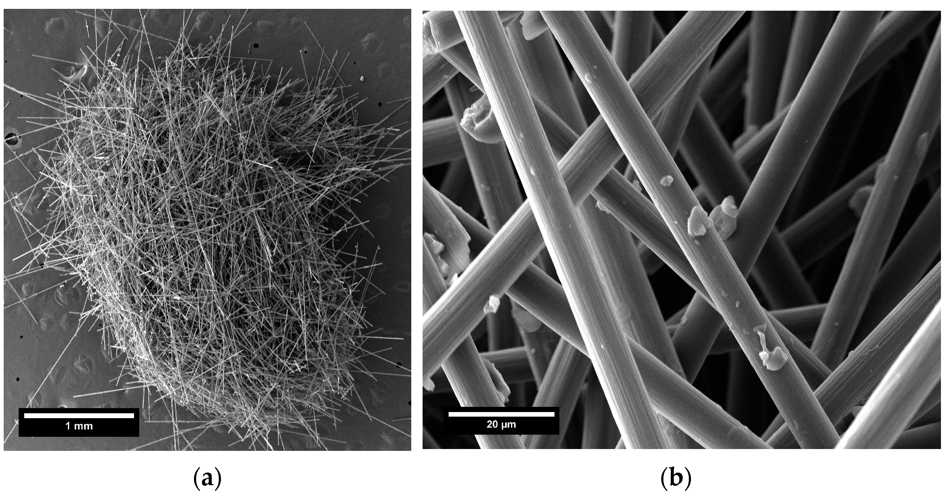
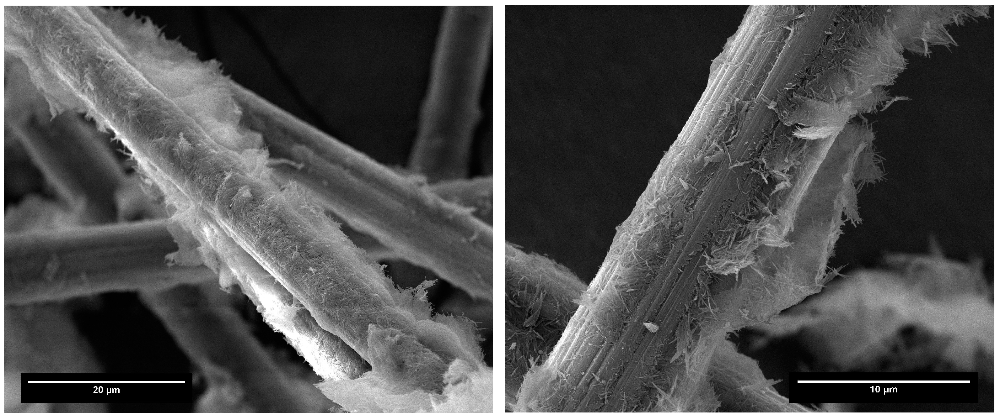
Figure 2 displays the morphology of an sCF agglomerate. The images were acquired by using the scanning electron microscope Tescan MIRA 3 FEG-SEM (Tescan, Brno, Czech Republic) at an operating voltage of 15 kV. Prior to the analysis, a randomly selected specimen of sCF agglomerate was placed onto an adhesive carbon pad which was attached on an aluminum SEM stub. Due the conductive characteristics of carbon fibers, no pre-treatment was conducted. The SEM micrographs show fibers of different lengths strictly intertwined within the single agglomerated structure. The fibers look relatively clean, with few small particles of non-uniform shape on their surface resulting from fragmented polymer resin that remain attached after the pyrolysis treatment.
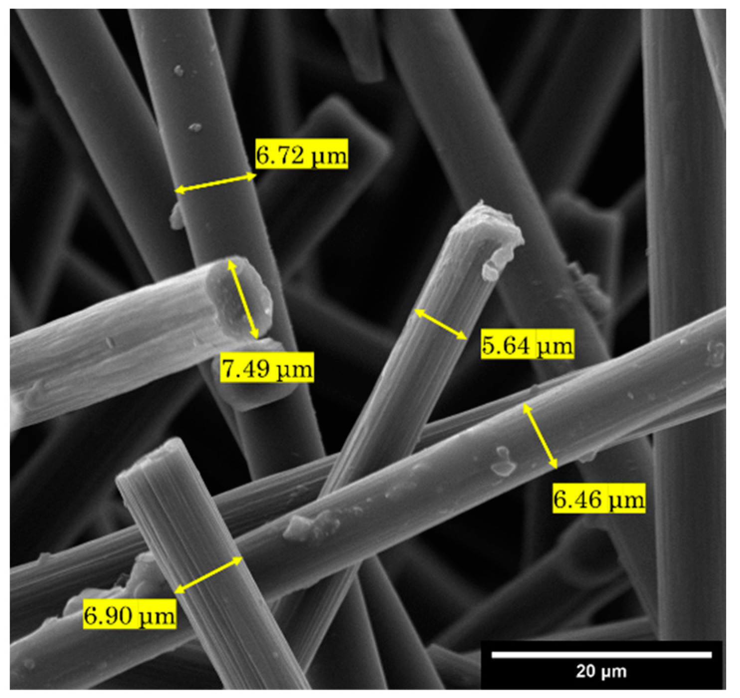
An image-processing size analysis (Figure 3) revealed an average fiber length of 550 μm and a diameter of 6.6 μm.
The average density of the sCFs, determined following Archimedes’ principle with a commercial density determination kit of the analytical balance Mettler Toledo ME54 (Mettler Toledo, Columbus, OH, USA), was 1.70 g/cm3.

2.2. Mixtures Composition and Details on Nanoclay Properties

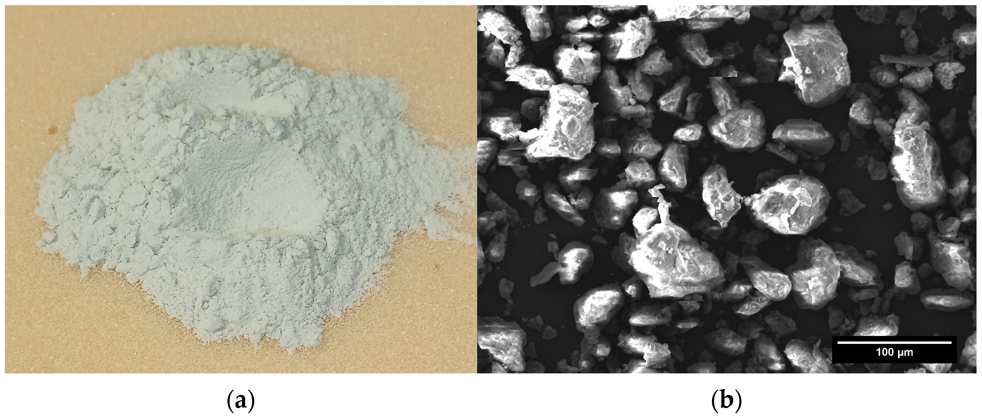
The cement mortar matrix was composed of CEM IV/A-type pozzolanic cement (strength grade of 42.5 R) produced by Italcementi S.p.A. (Bergamo, Italy), locally supplied fine-grained river sand (maximum nominal size of 1 mm), and tap water. Attapulgite nanoclay (ANC) from Lawrence Industries Ltd. (Tamworth, UK) is displayed in Figure 4a and was employed for conditioning the sCFs with the objective of deagglomerating the fibers and enhancing their dispersion and compatibility with the cement matrix. The surface morphology and chemical composition of the ANC were analyzed by the Tescan MIRA 3 FEG-SEM (Tescan, Brno, Czech Republic) equipped with an energy-dispersive X-ray spectroscopy (EDS) facility (Edax, Mahwah, NJ, USA). The sample was gold-coated prior to the analysis. The SEM micrograph in Figure 4b revealed a massive and aggregated morphology with a relatively smooth surface texture and sharp edges.
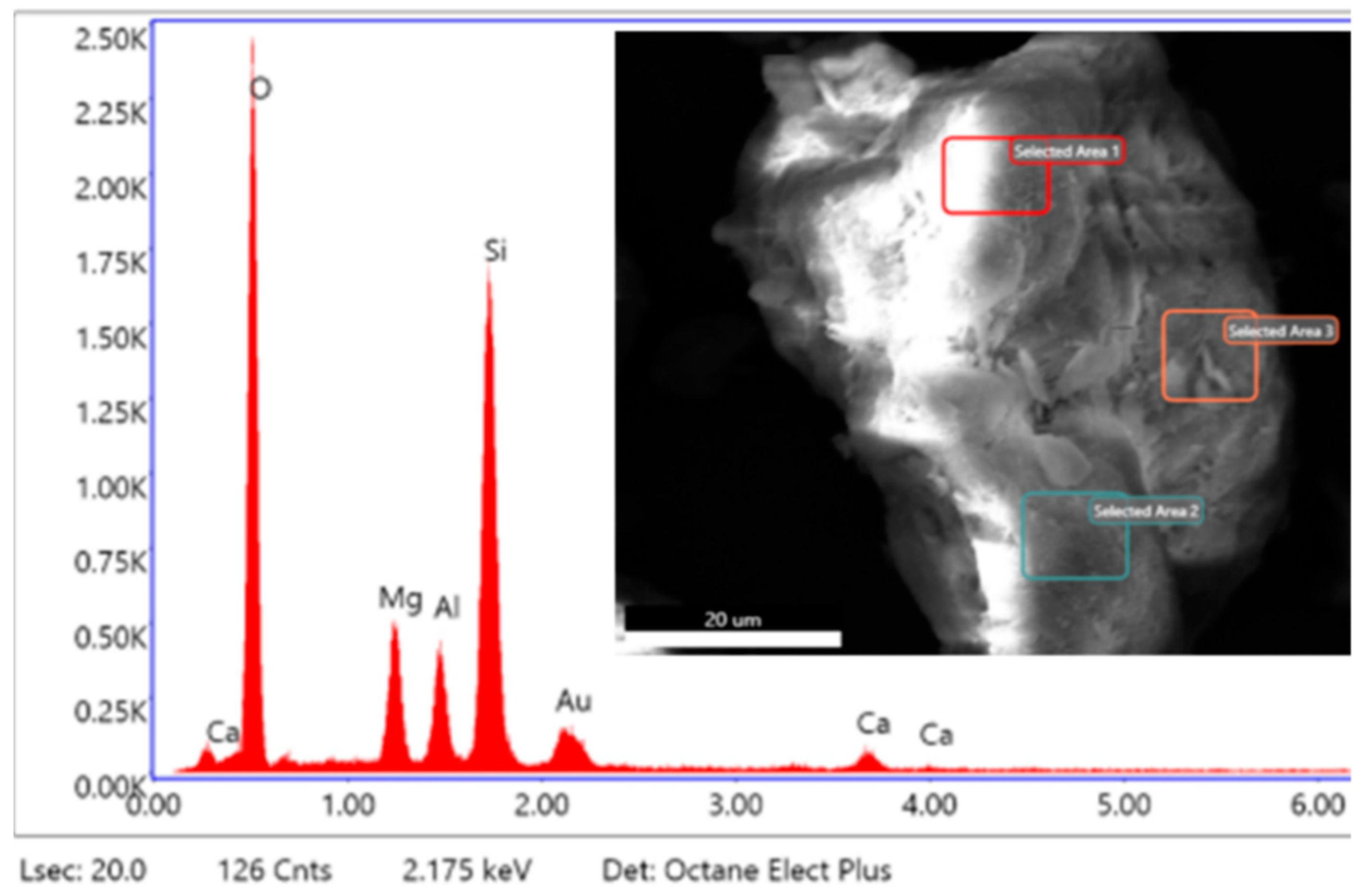
Apart from a gold (Au) peak deriving from the sputter-coating treatment, the EDS spectrum and quantitative elemental analysis of ANC highlights the presence of calcium (Ca), magnesium (Mg), aluminum (Al), silicon (Si), oxygen (O), as reported in Figure 5 and Table 1.
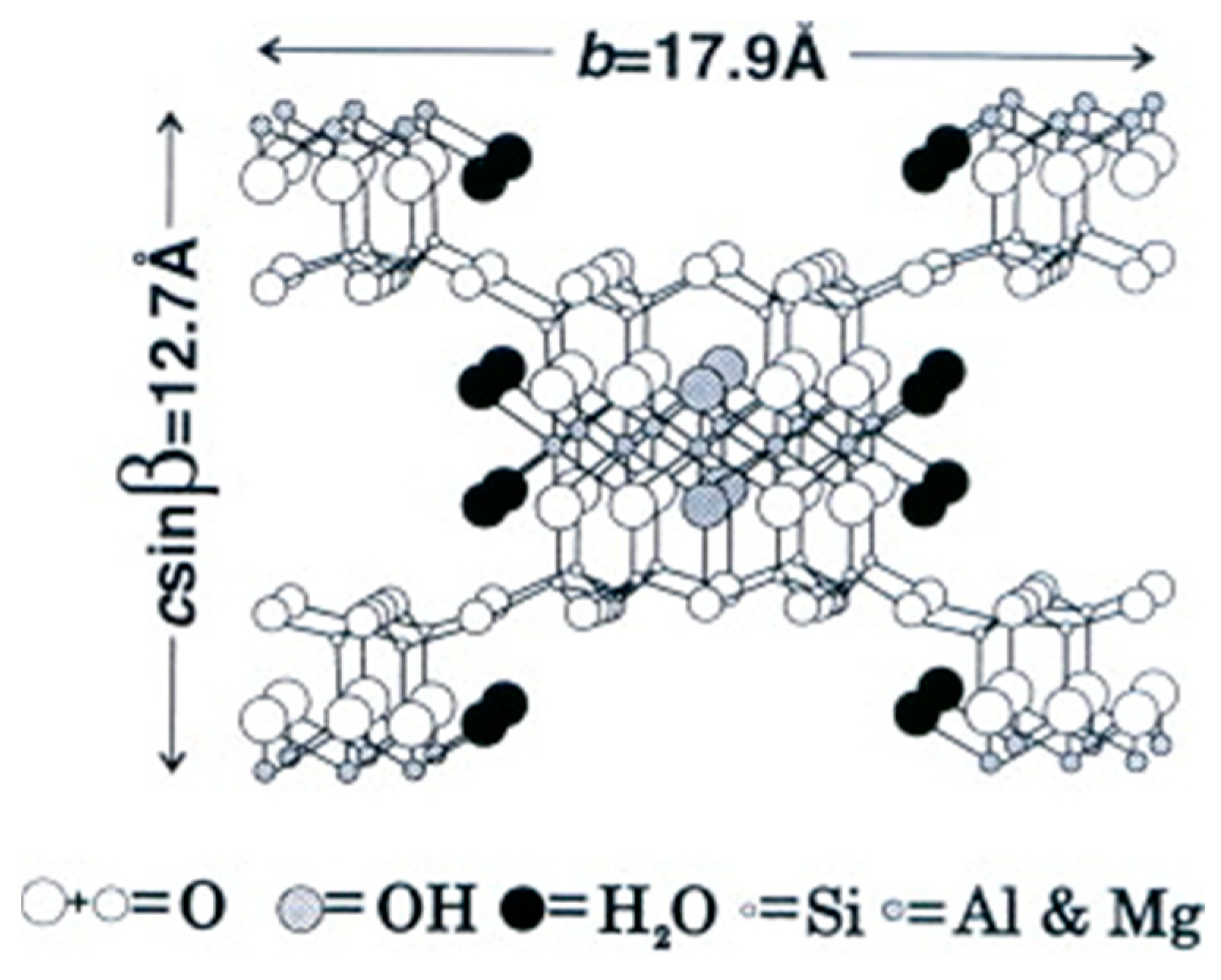
Indeed, ANC is a natural hydrated magnesium–aluminum silicate mineral having a theoretic structure formula of Si8O20Mg5(Al)(OH)2(H2O)4⋅4H2O. The mineralogical structure of attapulgite belongs to the 2:1 phyllosilicate classification, in which the sheets of silica tetrahedral are periodically inverted with respect to the tetrahedral bases (Figure 6). As a result of this inversion, the octahedral sheets are periodically interrupted, and terminal cations complete their coordination spheres with water molecules. The octahedral sheet is essentially an arrangement of closely packed six hydroxyl ions (OH) and oxygen atoms (O) enclosing a metal cation, mainly a Mg2+ ion. However, the Mg2+ ions in octahedral sites may be replaced by some polyvalent cations such as Al3+ and Ca2+ ions due to the isomorphism substitution effect. The discontinuity of the octahedral sheet leads to the formation of the so-called “clay channels”. These channels are open tunnels at the edge of a nanoclay unit and form its external surface, resulting in a fibrous (or “needle”-like) material morphology [21,22]. Such a macrostructure refers to the colloidal nature of nanoclay that develops when ANC is in the hydrated condition and the particles are adequately dispersed in a liquid medium. However, ANC is commercially supplied to users in dry and non-colloidal form (powder or granules as shown in Figure 4a,b above) in which the needles are packed close to each other to give rigid aggregates of micrometric dimension [23].
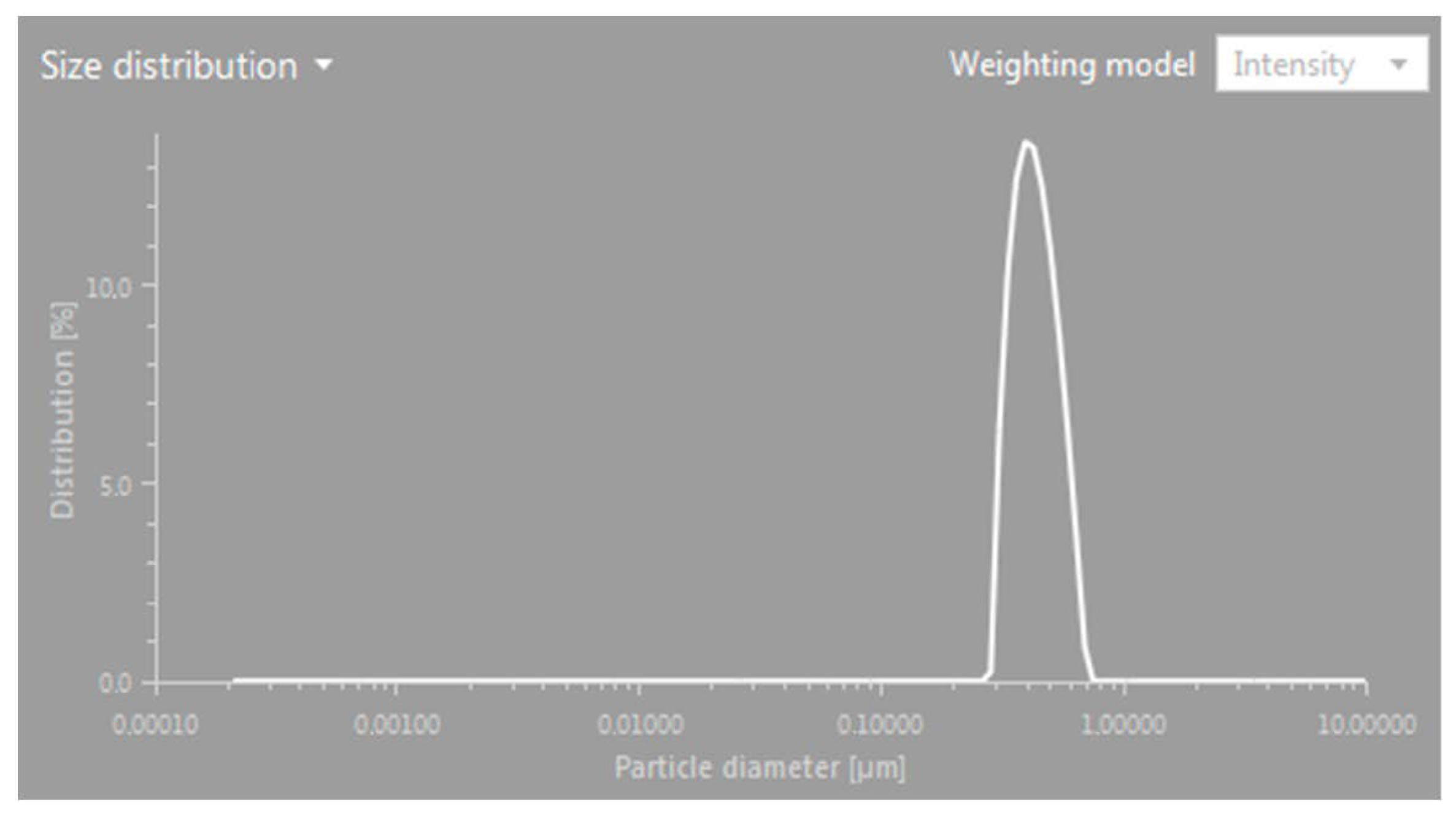
The dynamic light scattering (DLS) method was performed to accurately determine the average size of the ANC particles. A hydrodynamic diameter (HD) measurement of the particle was made by a Litesizer 500 (Anton Paar, Graz, Austria) DLS analyzer. In a typical procedure, 0.5 g of ANC was dispersed in 50 mL of bidistilled water and stirred magnetically at 500 rpm for approximately 30 min. Subsequently, the solution was further diluted until a clear analyte was obtained for analysis. The dynamic light scattering (DLS) size distribution profile is presented in Figure 7. Results from three consecutive measurements revealed that the hydrodynamic diameters (HDs) ranged from 0.75 μm to 3.38 μm.

2.3. Conditioning of sCFs via ANC-Based Treatment

Adopting ANC in the construction material field is an emerging and most promising approach to improve the properties of cement-based materials. The addition of nanoclay increases thixotropic behavior and improves the fresh-stage stiffening of early-age cementitious mixtures. In addition, as a kind of nano-pozzolanic material, ANC not only reduces the pore size and porosity of the cement matrix, but also improves the strength of the cement matrix through pozzolanic reactions [24]. Compared with other nano-additives employed for functionalizing high-performance cement-based systems (such as carbon nanotubes, carbon nanofibers, graphene, nano-SiO2, nano-Al2O3), nanoclay is more cost-effective and less harmful to the environment and human health. This is attributed to the fact that nanoclay can be produced in existing, full-scale production facilities, and the basic material (clay) is a type of readily available natural mineral [25]. Furthermore, the effectiveness of ANC as a nano-additive and as a surface functionalizing agent for reinforcing materials in cementitious composites was also demonstrated by the authors in previous works [26,27]. These reasons prompted the use of nanoclay for the physical–chemical surface conditioning of sCFs aimed at both minimizing the fibers’ aggregation and promoting their homogeneous distribution in the matrix while ensuring adequate carbon–cement chemical compatibility.
The conditioning treatment used on the sCFs involved the preparation of a nanoclay-based slurry for treating fibers and enhancing their deagglomeration. To evaluate the effectiveness of the proposed conditioning method, a trial slurry was prepared by mixing sCFs and ANC, in the same weight ratio (1:1), with 100 mL of tap water. First, the sCFs were manually deagglomerated, weighed (1 g), and put inside a glass beaker. Then, water was added, and a magnetic stirring was performed for 1 min. at 500 rpm. At this point, the ANC was poured and the whole mixture was blended at 500 rpm for a further 30 min. To evaluate the post-conditioning properties of carbon fibers through chemical and SEM morphological microanalysis, the ANC-sCFs slurry was poured onto a watch glass and dried in an oven at 100 °C for 24 h. Upon visual examination of the dried sample, the sCFs exhibited homogeneous dispersion within the clay matrix, and no agglomeration of carbon fibers was observed. Figure 8 illustrates the key steps involved in the preparation of the nanoceramic slurry and the conditioning of the sCFs.
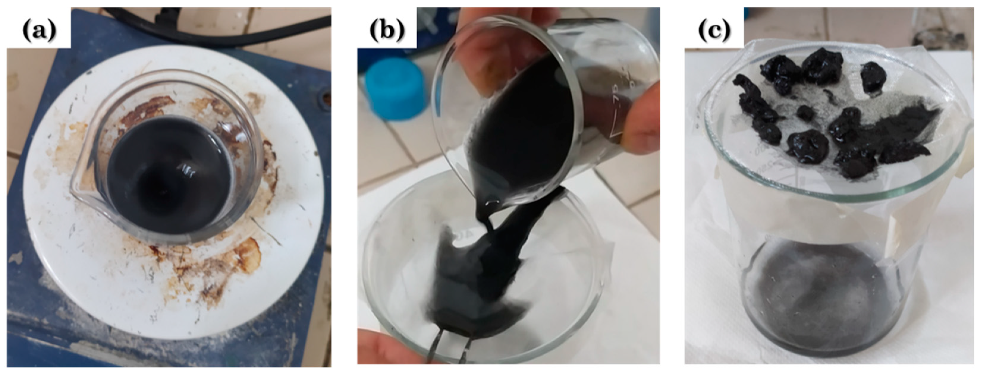
To provide a counterproof, an experiment was conducted to disrupt the agglomerates of sCFs by employing magnetic stirring in water alone, without the addition of ANC, while keeping the same mixing parameters (500 rpm for 30 min). Figure 9 illustrates the various stages of the procedure, emphasizing the appearance of the filtered mixture following the treatment. In this case, the attempt to deagglomerate the sCFs using this method proved to be ineffective, as evidenced by the presence of numerous clusters of carbon fibers collected on the grid.

2.4. Mix Formulations

A total of ten cement mortar mixtures, divided into four groups, were prepared with different contents of sCFs (with and without nanoceramic conditioning treatment) and ANC.
The first group (named sCF_i, where i is 0.5, 0.75, and 1) consisted of the mixtures loaded with different levels of unconditioned sCFs, i.e., 0.5%, 0.75%, and 1% by weight over the weight of the cement binder, respectively. In this case, cement and sand were dry-blended manually in a bucket. Separately, the sCFs were mixed with water for 2 min. using a drill mixer. Then, the “water and sCFs” mixture was gradually added to the dry blend (cement and sand) and drill-mixed until a homogeneous cementitious compound was achieved. After mixing, the fresh compound was cast into standard prismatic specimen molds (40 mm × 40 mm × 160 mm) and then slightly vibrated to remove air voids. The second group (named sCF-ANC_i, where i is 0.5, 0.75, and 1) involved the FRCCs that incorporate sCFs conditioned with the nanoceramic slurry. Herein, the slurry containing ANC and sCFs (1:1 weight ratio) was prepared in accordance with the procedure defined in Section 2.3, but using all the mixing water required for the manufacturing of mortar samples. After the hand-mixing of cement and sand, the slurry containing the conditioned fibers was added. Following the same procedure implemented for the first group, the fresh compounds were drill mixed and poured into prismatic molds for making specimens. The third group (named ANC_i, where i is 0.5, 0.75, and 1) comprised the sCF-free cementitious formulations, including three different additions of ANC in the same dosage implemented for producing the slurries. For this set of samples, nanoclay was dry blended with cement and sand. Then, the mixing water was gradually added. Mixing and mold-casting operations were performed in accordance with the procedure described above. Standard cement mortar samples (without addition of sCFs and ANC) were prepared as the control group (CTR). After mold-casting, all specimens were demolded at the age of 1 day and cured in water for 28 days before testing. The mix proportions (referring to 1 m3 of fresh mixture) of the cement mortars investigated in this research are tabulated in Table 2. In all samples, the amount of sand and cement was kept constant. For the nanoclay-free mix formulations, the water amount was selected to achieve a water-to-cement (w/c) ratio of 0.42. In accordance with the Powers’ model, a w/c ratio of 0.42 is technically recognized in concrete technology as the optimal condition for achieving complete hydration of a cementitious system [28]. With the addition of the nanoclay, the amount of water was slightly increased to consider the effect of hydration related to the nanoceramic additive while preserving 0.42 as a “target” ratio.

3. Testing

3.1. Microanalysis of sCFs after ANC-Based Conditioning

3.1.1. SEM and EDS Analysis

To perform microanalysis on the post-conditioning sCFs, small pieces of the dried nanoceramic slurry were mounted onto a carbon tape and gold coated. With the same experimental facilities implemented for the raw materials characterization, the SEM device connected by a secondary electron (SE) detector of 15 kV of accelerating voltage and EDS analyzer were used to examine the microstructure and the surface chemical composition of fibers, respectively.

3.1.2. Fourier-Transform Infrared Spectroscopy (FT-IR)

The effect of the ANC-based treatment on the surface modification of sCF was also studied by FT-IR-reflectance spectrometry. The detection was performed by a PerkinElmer Spectrum 3 FT-IR spectrometer (PerkinElmer, Waltham, MA, USA) including a Diamond KRS-5 attachment with attenuated total internal reflectance (resolution of 4 cm−1, 4 scans, wavelength range of 4000–400 cm−1).

3.2. Characterization of Fiber-Reinforced Cement Mortars

3.2.1. Three-Point Flexural Testing

The 28-day flexural strengths of fiber-reinforced cement mortars were tested using a Zwick-Roell Z10 universal testing machine (Zwick-Roell GmbH & C. KG, Ulm, Germany) equipped with a load cell of 10 kN. The test (three-point bending) was carried out in accordance with the ASTM C348-02 standard method [29], setting a crosshead displacement speed of 1 mm/min and a span length of 100 mm. Strain was recorded with a displacement transducer in contact with the sample. Three beam-shaped specimens were used for each formulation.

3.2.2. Compression Testing

After the flexural test, the beams were broken into two pieces. Cubes of 40 mm per side were produced by cutting and tested in compression. Cutting operations were made with a Labotom-3 abrasive cut-off saw (Struers Inc., Cleveland, OH, USA) equipped with a silicon carbide abrasive cutting disk (Hitech Europe, Milan, Italy). For compression testing, a Zwick-Roell Z150 universal testing machine (150 kN capacity) was utilized at a loading rate of 2 mm/min following the ASTM C109/C109M standard [30]. Five specimens for each formulation were tested. Axial strain (%) was measured using the crosshead displacement as the change in specimen’s height, due to the compression load, divided by the original height multiplied per 100%. The crosshead displacement was also used in calculating the static elastic modulus. The elastic modulus was taken as the slope of the initial linear region of the load–strain curve in the range between 10 MPa and 20 MPa.

3.2.3. SEM and EDS Analysis

SEM and EDS microanalysis were also conducted on the fracture surface of the cement mortar samples. Small specimens of 3 cm2 (surface) × 1 cm (height) were bonded to the SEM sample stage with double-sided carbon tape. To obtain good imaging quality with minimal electrostatic charging effects due to the non-conductive characteristics of the material, the specimens were sputter-coated with a layer of gold prior to the analysis, using an Edwards S150B sputter-coater (Edwards Ltd., Burgess Hill, UK).

4. Results and Discussions

4.1. Microanalysis of sCFs after ANC-Based Conditioning

The deagglomeration and adequate dispersion of the sCFs in the cement medium was a crucial factor to solidify the enhancement of the mechanical behavior of fiber-reinforced mortars. As addressed in Section 2.3, the implementation of the nanoclay slurry proved to be an effective method to disaggregate the carbon fiber agglomerates, allowing a homogeneous distribution of the fibers in the ceramic mixture. The principal mechanisms that occur in the deagglomeration of carbon-based aggregation using the ANC-based dispersing fluid are: (1) the infiltration into the fibrous agglomerated structure by the dispersing medium; (2) the change in surface energy that ANC induces on the fibers. In this regard, the viscosity of the dispersing fluid is a primary factor to determine an adequate infiltration inside the agglomerate, as well as an effective conditioning and coating on the fibers [31]. In accordance with the study conducted by Chuang et al. [32], if the mass fraction of the dispersing agent (in this case ANC) is too small, the viscosity of the dispersant solution is not enough to coat carbon fibers. Contrarily, if the mass fraction is too large, the viscosity of the solution is too great, the fluidity is poor, and carbon fibers can’t disperse separately. The ANC-based slurry designed in this research seems to provide a rheology with good potential to infiltrate and wet the sCF agglomerates. The full infiltration of the dispersing fluid would reduce the strength of carbon agglomerates, facilitating their untangling and the consequent separation of the fibers in the solution. Furthermore, ANC would have assisted the fibers’ dispersion by reducing the interfacial surface energy mismatch between hydrophobic sCF and water (surfactant-like behavior). Generally, the total surface energy comprises polar and non-polar (dispersive) components. The high polarity of OH groups, at the ends of clay structure, provide strong affinity with water molecules by the formation of hydrogen bonds. Conversely, the positive charge distribution on the ANC surface, due to the contribution of metal cations, promotes the van der Waals force and other non-site-specific interactions (dispersive component) with carbon fibers (Figure 10). Such a mechanism produces an increase in the wettability of the fibers’ surface, promoting their isolation in polar liquids like water. This assumption is supported by a previous study from Zabihi et al. [33] on the surface modification of carbon fibers with nanoclay for enhancing the interfacial adhesion properties in epoxy resin matrix composites.

4.1.1. Microstructure Analysis

Figure 11 shows the results of ANC-based conditioning on sCFs. Notably, the SEM analysis reveals the presence of nanoclay adhering to the fiber surface in a characteristic hydrated needle-like form. These observations indicate an interaction between the clay and carbon. The resulting ceramic coating contributes to the increased hydrophilicity of the sCFs, thereby improving their affinity and dispersion in water. Additionally, as also verified by Zabihi et al. [33], conditioning with ANC caused some evident longitudinal grooves and increased surface roughness on fibers. The presence of these surface defects and channels can certainly result in improved mechanical interlocking and better interfacial adhesion between sCFs and the cement matrix, representing the key prerequisite for maximizing the mechanical behavior of the final FRCC [16].
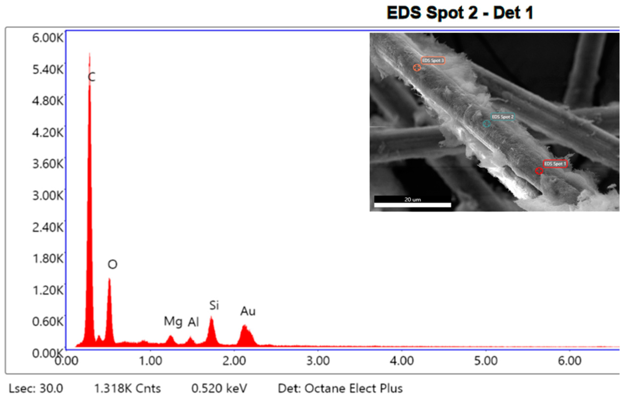
The adhesion of ANC on the carbon fiber surface after conditioning was further confirmed by the presence of Si, Al, and Mg detected by EDS analysis (Figure 12).
The elemental composition from the EDS analysis of the sCF following the surface activation treatment with nanoclay is indicated in Table 3.

4.1.2. Surface Functional Groups

FT-IR spectra for bare sCFs, ANC, and sCFs after conditioning with nanoclay are plotted in Figure 13.
Limited chemical information can be obtained from bare sCFs due to the challenge of recording a high-quality FT-IR signal caused by their highly absorbing nature (resulting in a black specimen). Nonetheless, a small absorption band in the range of 1500 cm−1 to 1250 cm−1 was identified, which is attributed to the stretching vibration of C=C in the graphite structure [34]. In the FT-IR spectrum of raw ANC, the absorption peaks at 3543–3614 cm−1 were assigned to the stretching vibration of the O–H units within the clay interlayer bonded to Al and/or Mg. Additionally, the band at 1651 cm−1 corresponds to H–O–H bending vibrations of bonded water. The characteristic absorption peaks at 1195 cm−1 and 975 cm−1 were attributed to the perpendicular stretching vibration of the Si–O bond. The IR spectra in the range of less than 500 cm−1 exhibited a combined band due to the stretching vibrations of the Mg–O bond and the bending vibrations of the O–Si–O and Al–O–Si bonds [35,36,37]. The spectrum of sCFs after conditioning with ANC exhibited the same chemical groups present on the surface of the raw nanoclay. This confirms the influence of the ANC-based treatment on the surface of carbon fibers.

4.2. Mechanical Characterization of Fiber-Reinforced Cement Mortars

4.2.1. Three-Point Flexural Testing

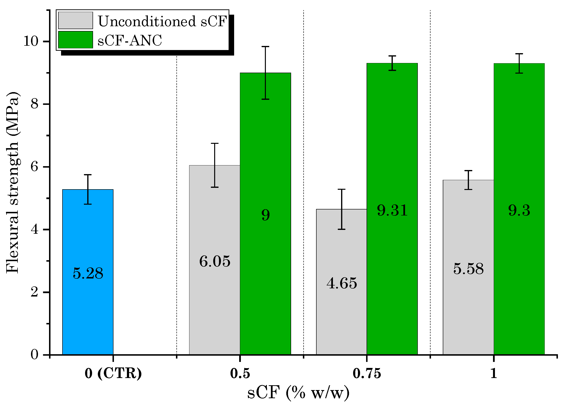
The results of the flexural strength tests for carbon-fiber-reinforced cement mortars are illustrated in Figure 14. The influence of sCFs on the flexural strength of FRCCs was rather unclear and changing in the case of unconditioned fibers. With respect to the CTR sample, depending on the sCF content, FRCC exhibited a marginal increase (+14.6% for sCF_0.5 and +5.7% for sCF_1) or decrease (−12% for sCF_0.75) in its flexural strength. Overall, it is evident that the addition of untreated carbon micro-fibers did not lead to any significant benefit for the mechanical performance. In contrast, incorporating sCF processed with ANC resulted in a significant enhancement in flexural properties. Compared to the CTR mixture, the increase in flexural strength ranged from +70.5% for the sCF-ANC_0.5 sample to +76.3% for the sCF-ANC_0.75 sample. Compared to the mortars incorporating unconditioned sCF, the increase in strength was 49%, 100%, and 67% for the sCF-ANC_0.5 mix, sCF-ANC_0.75 mix, and sCF-ANC_1 mix, respectively. Despite the effectiveness of the nanoceramic surface activation of fibers on the strength improvement, the highest content of sCF (1 w/w%) did not lead to a change in flexural strength. With respect to the CTR sample, the increase in strength for the sCF-ANC_1 mix (+76.1%) was very close to that found for the sCF-ANC_0.75 sample. What may hinder further enhancement in flexural performance can be traced to the difficulty of ensuring efficient dispersion with increasing sCF content. Defects induced by fiber agglomeration are unfavorable to the strengthening effect, limiting further growth in the mechanical properties of the mortars [38]. Considering the results of this study, an sCF concentration of 0.75 w/w% was the optimal fiber content in which the strengthening effect of fiber dominates and the best condition in terms of the occurrence of dispersion through the nanoclay conditioning treatment.
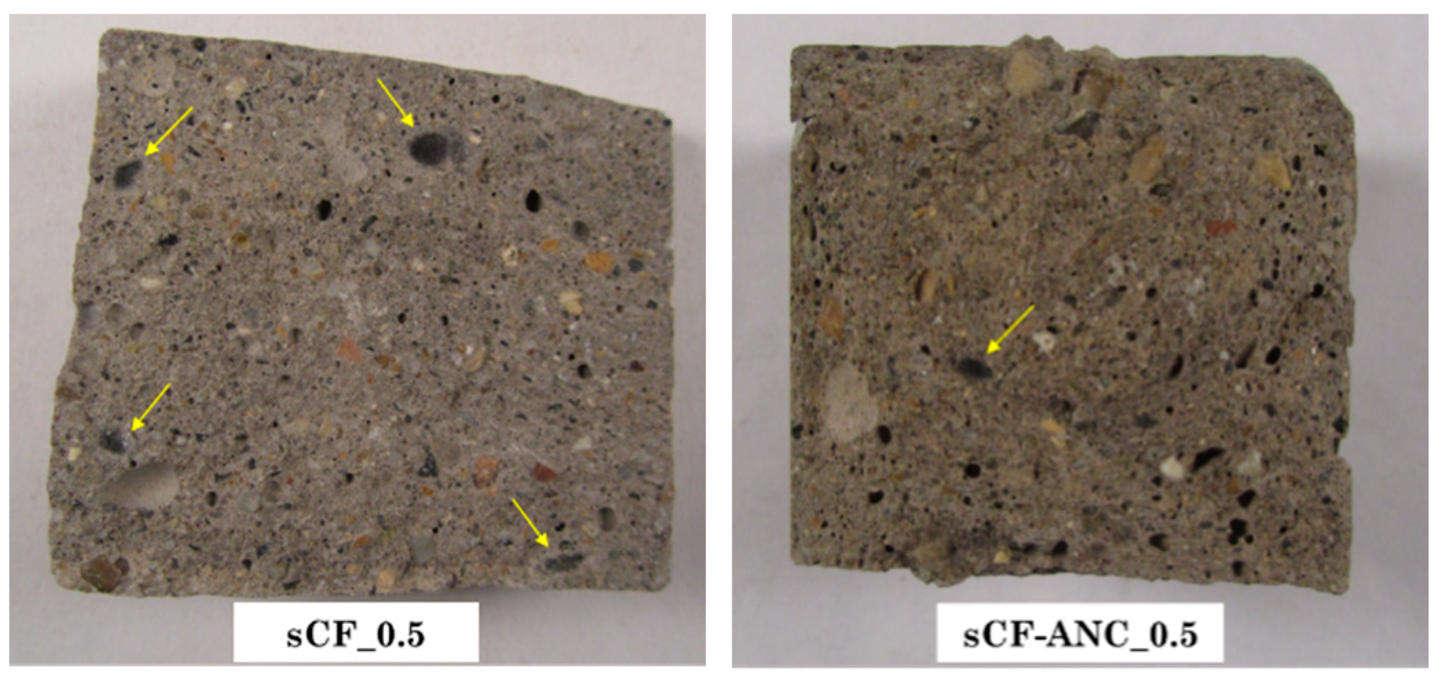
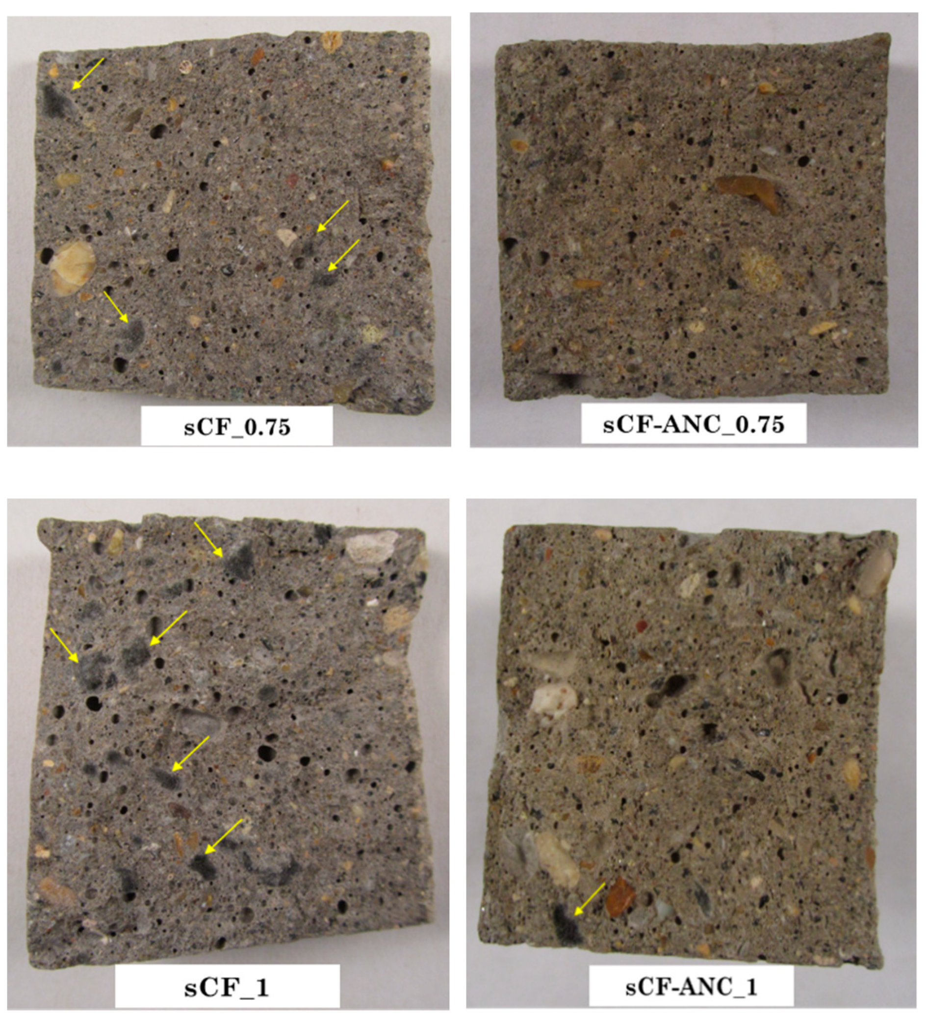
The beneficial effect of ANC-based treatment can be ascribed to two main factors. Firstly, the absence of the proper dispersion of unconditioned sCFs within the cementitious compound leads to the formation of fibrous agglomerates in the matrix, resulting in compromised interfacial bonding. As a consequence, the fibers are unable to effectively share external loads with the cement binder, creating a weak zone within the concrete. This limitation hampers the potential improvement in flexural behavior [39]. Furthermore, the hydrophobic nature of carbon fibers, apart from contributing to the consolidation of sCF clusters within the matrix, also leads to an increase in the material’s porosity [40]. The conditioning of the fibers with ANC helps alleviate the influence of these aforementioned phenomena. Nanoclay slurry would favor the dispersion of the fibers according to the mechanisms described in Section 4.1, avoiding the presence of agglomerates harmful for the strength performance of the cement mortars. Furthermore, due to the hydrophilic nature of ANC, the conditioned sCFs are more hydrophilic, which makes the fibers more easily dispersed in the cement-based material and the microstructure denser by minimizing the entrapped air (porosity) introduced into the matrix during mixing. A similar result was achieved by Lu et al. [41], who implemented a nano-SiO2 surface modification method for carbon fibers to improve the strength and microstructure development of FRCCs. The functionalization of carbon fibers with nano-SiO2 proved to be less efficient than the ANC-based conditioning treatment proposed in the present work. Indeed, Lu et al. [41] recorded a maximum increase in flexural strength of 22% for a fiber content of 0.5%. Fractography observations (Figure 15) confirmed the near total disappearance of fibrous agglomerates and a significant reduction in porosity in the sCF-ANC samples compared to the counterparts incorporating unconditioned fibers.
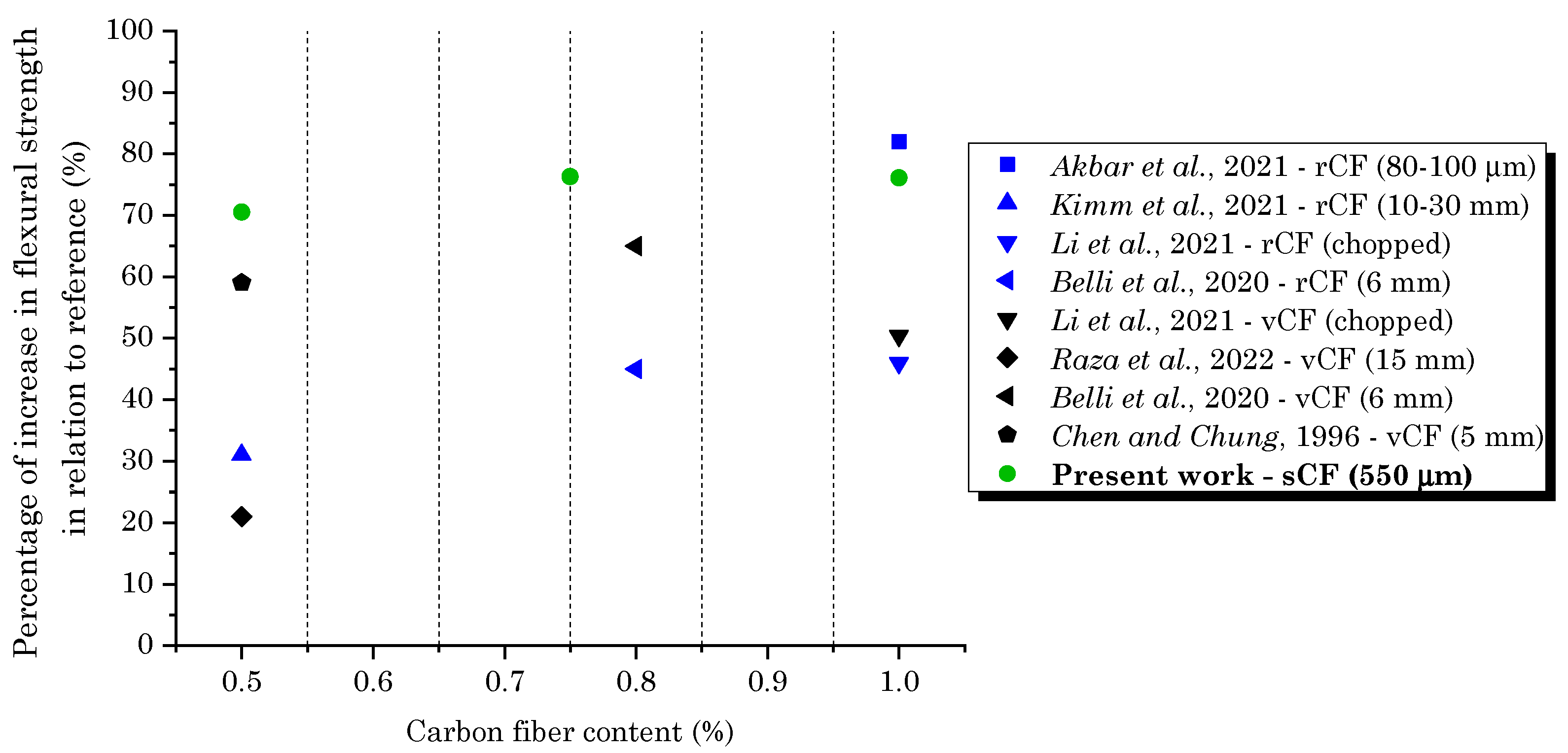
Another valuable result found in the present work is that the strength improvement achieved by using this type of waste fibrous filler after nanoceramic conditioning is superior to the mechanical properties achieved by other researchers [16,17,18,42,43,44] who have employed vCFs or rCFs as concrete reinforcements (Figure 16). Notably, only the configurations with the best strength performances were considered in this survey, i.e., the carbon fiber contents that promoted the greatest increases in relation to the plain reference matrix. For the present work, the optimal mix that contributed to the greatest mechanical strength properties was the sCF-ANC_0.75 sample. In this comparative analysis, the length of the fibers was also detailed. Considering the typical diameter for carbon fibers (6–7 μm), the fiber length is closely related to their aspect ratio (fiber’s length over its diameter) which represents a considerable parameter governing the physical and structural properties of FRCCs. The investigation in Figure 16 highlights that using shorter fibers (lower aspect ratio) results in better mechanical strength behavior. While ordinary chopped fibers with lengths greater than 5 mm are effective in enhancing the post-cracking response and ductility of the material through crack-bridging mechanisms, the inclusion of micro-fibers, including the sCFs employed in this study, offers a larger quantity of available reinforcing material to strengthen the cracked sections, resulting in a greater improvement in strength. Additionally, shorter fibers are more easily dispersed within the cement matrix. The use of carbon fibers can pose challenges during the mixing process, particularly when longer fibers are utilized, leading to the formation of clusters [45]. These findings emphasize the significance of ANC treatment on sCFs to optimize the final strength performance of cementitious composites.

4.2.2. Compression Testing

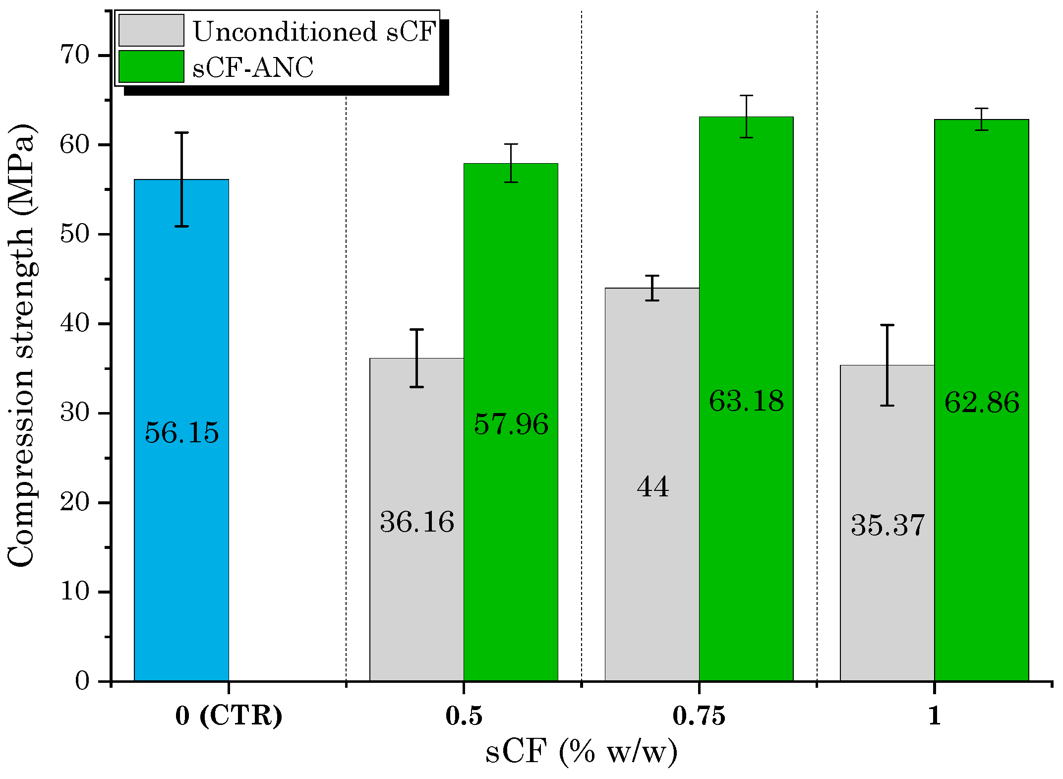
In accordance with the results of flexural testing, the conditioning of sCF with ANC implied improvements in compression strength performance both with respect to the CTR sample and the mixtures incorporating unconditioned carbon fibers (Figure 17). All cement mortars added with untreated fibers show a clear worsening of the mechanical properties. Compared to the CTR mix, the compressive strengths of the sCF_0.5, sCF_0.75, and sCF_1 samples were reduced by 35.6%, 21.6%, and 37%, respectively. For the mixes containing nanoclay-activated sCF, the strength of the fiber-reinforced mortars exceeded that of the un-reinforced control sample. With respect to the CTR mix, the maximum rate of increase was 13% for the sCF-ANC_0.75 sample. For the sCF-ANC_0.5 and sCF-ANC_1 mixes, the increments in strength performance were 3.2% and 11.9%, respectively. Unlike the flexural behavior, the compressive strength of FRCC was only slightly improved with the addition of ANC-treated sCFs. It is known that the strengthening contribution of the fibers is more significant under flexural loads since the compression strength is mainly governed by the structural characteristics of the matrix, including the porosity, shear modulus, and ultimate strain [46]. These observations provide evidence for the detrimental impact of sCF clusters on the structural integrity of the matrix when proper dispersion and compatibilization of carbon fibers are not achieved. In fact, all formulations incorporating unconditioned sCFs demonstrated lower strength performance compared to the CTR sample. This highlights the importance of ensuring adequate dispersion and compatibilization of carbon fibers to achieve optimal strength properties in the composite material.
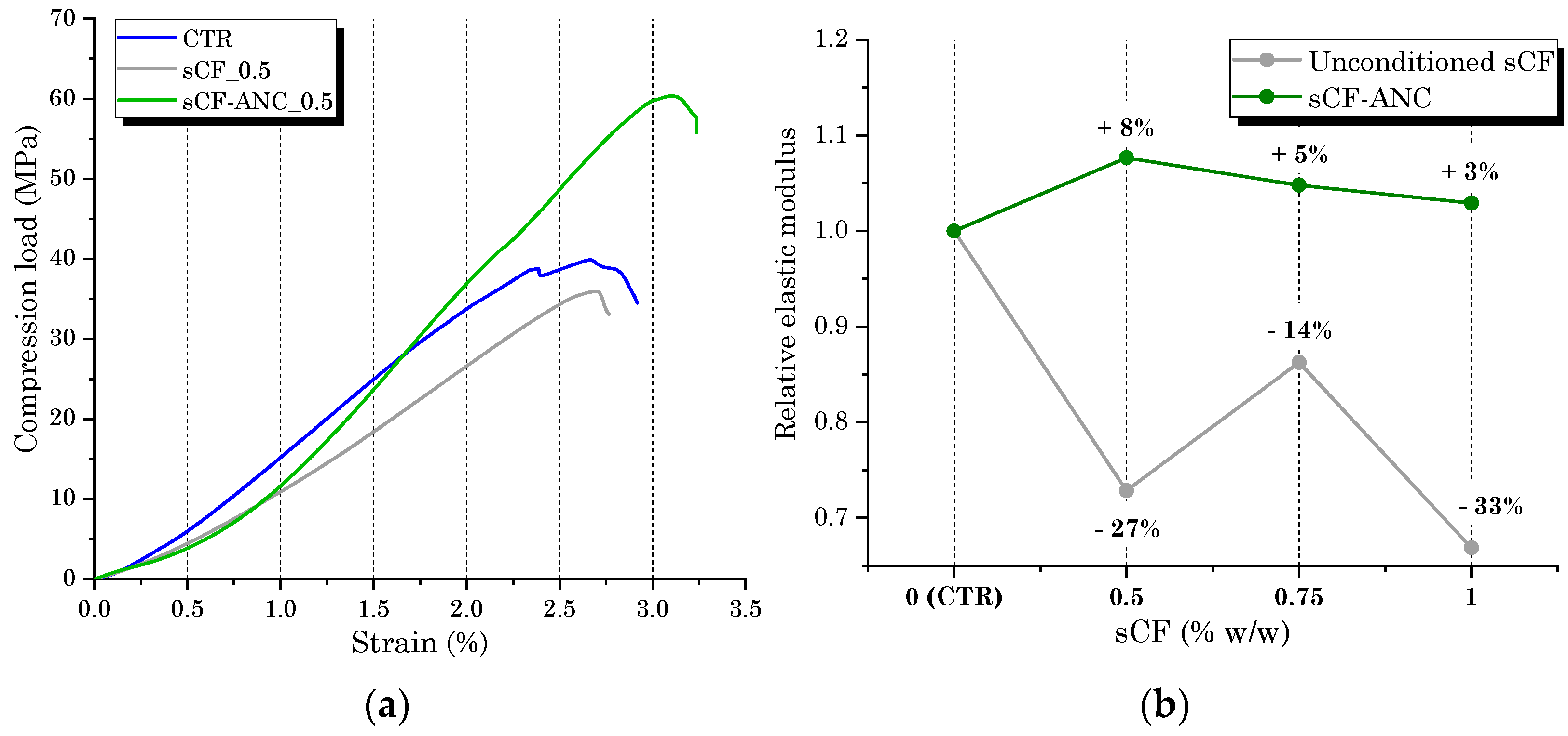
From the compression testing, the load–strain behavior and stiffness of the cement mortars were investigated as a function of the sCF addition and fiber conditioning with ANC. Figure 18a illustrates the load–strain relationship (CTR, sCF_0.5, and sCF-ANC_0.5 samples) and relative elastic modulus (Figure 18b) of all FRCC samples to scrutinize the behavior of mortars following the addition of carbon fibers and the treatment with nanoclay. Then, the relative static elastic modulus was defined as the ratio of the modulus of fiber-reinforced mortars to that of the CTR sample. In good agreement with the compressive strength results, the relative elastic modulus displays opposite trends following the addition of unconditioned and ANC-treated fibers. Compared to the CTR sample, the presence of untreated fibers drastically reduced the composite’s stiffness. The resulting negative impact is attributed to the sCFs’ agglomeration into the matrix, the formation of voids between the cement paste and carbon agglomerates and increased entrapped air (porosity) as the percentage of fiber is increased [47]. The extent of the elastic modulus improvement in the samples incorporating conditioned sCFs was attributed to the successful fiber dispersion. The successful dispersion of micro-fibers within the cement matrix led to a decrease in the fiber-free area in the material, resulting in improved mechanical performance due to the higher stiffness of carbon fibers compared to the cement matrix. The measurement of the elastic modulus highlights the significance of the interfacial bond between the cement matrix and the rigid reinforcement. The improvement observed after conditioning with nanoclay indicates the successful attainment of compatibility between the sCF and the cement binder, enabling the carbon reinforcement to make a substantial contribution to the stiffness of the composite prior to failure.

4.2.3. SEM and EDS Analysis

The microstructure of the cement composites reinforced with unconditioned sCFs is shown in Figure 19. The SEM micrograph in Figure 19a revealed the presence of some “islands” of carbon fibers (indicated by the yellow arrows) representing sCF agglomerates interspersed in the matrix. Upon closer examination, cement paste trapped between the fibers within the agglomerates was observed, shown in Figure 19b. The grain-like morphology of the material indicated the presence of a cementitious phase that was not fully developed at the microstructural level, likely due to the inhibitory effect of the sCF clusters on the proper growth of hydration products.
This effect was investigated by EDS chemical analysis. It is expected that the Ca/Si ratio, having a great significance for the C–S–H gel structure (dominating component of cement hydration) [48], varies according to the hydration state of the binder. The cement phase embedded into sCF agglomerates (Figure 20a) is different from the bulk cement matrix (Figure 20b) in its chemical characteristics. As also quantified in Table 4, the Ca/Si ratio of the bulk matrix surpassed the Ca/Si ratio of the cementitious phase entrapped within the fibers, demonstrating that the hydration degree of the cement embedded into the carbon agglomerates is lower than the hydration degree of the bulk cement matrix. These findings suggest that the presence of carbon clusters creates regions within the cement matrix that have reduced microstructural development and lower strength, serving as weak points in the final composite. This observation aligns with the results obtained by Yan et al. [49], who investigated the microstructure and chemical properties of cement mortars incorporating carbon-based reinforcement.
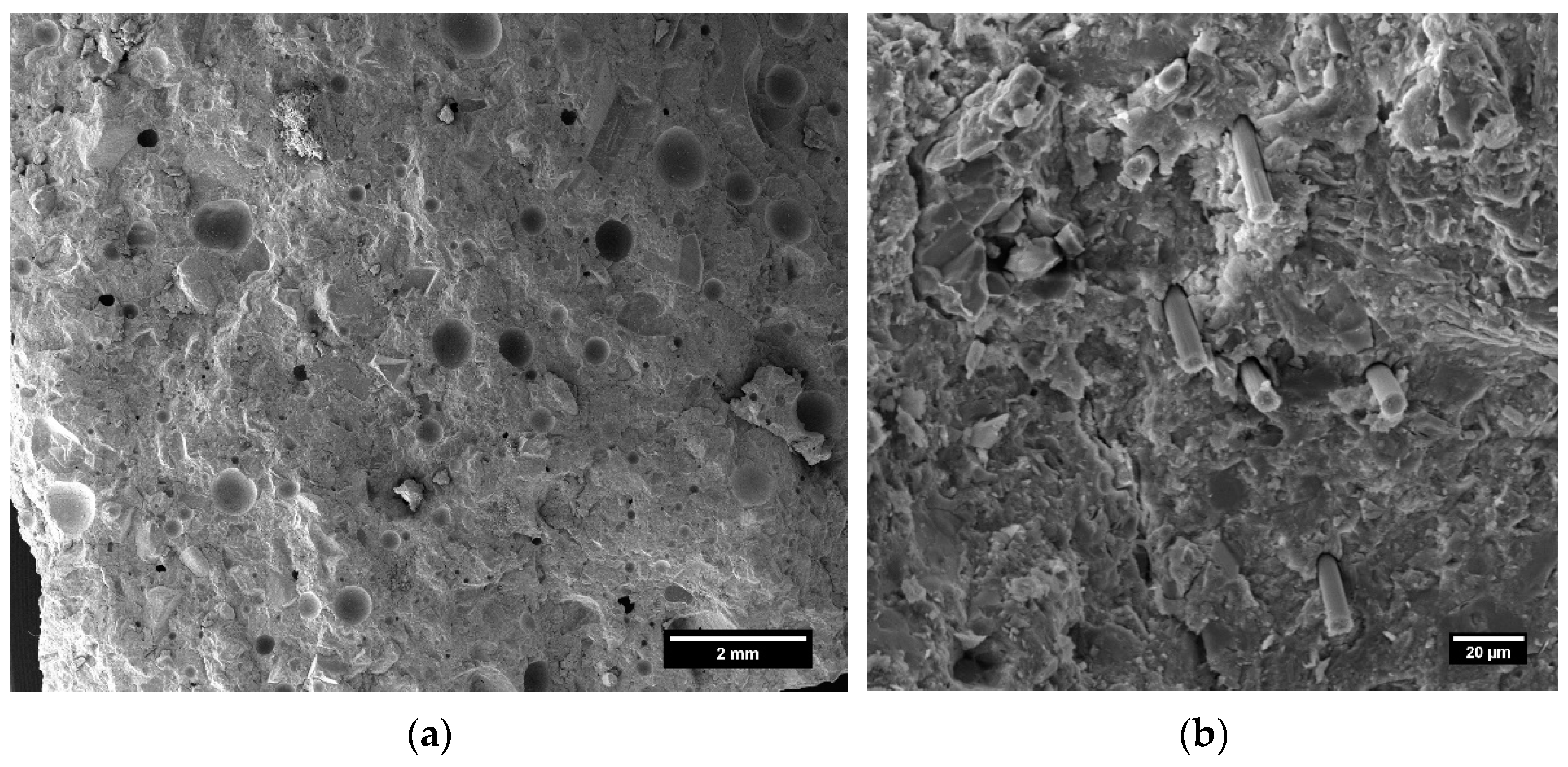
After the conditioning with ANC, the microstructure of the carbon-fiber-reinforced mortar appeared free of fibrous agglomerates (Figure 21a), with well dispersed and isolated carbon fibers inside the matrix (Figure 21b).
Figure 22 elucidates the interfacial transition zone (ITZ) between the cement matrix and sCFs after conditioning with ANC. The micrographs revealed that, once sCFs are pulled out (Figure 22a), microcracking appears within the matrix around the fibers due to the enhanced ITZ bonding between the cement and conditioned sCFs (Figure 22b). If proper dispersion is ensured, the inclusion of high-performance fibers can mitigate the extension of microcracks and block their propagation, as well as consuming energy during the fracture process. In this regard, after the brittle failure of the cement matrix, additional energy must be consumed to pull the fibers out of the binder. This additional energy consumption manifests itself in higher failure loads, toughness, and cracking behavior in the FRCCs [50,51].

4.2.4. Mechanical Characterization of ANC Group Samples

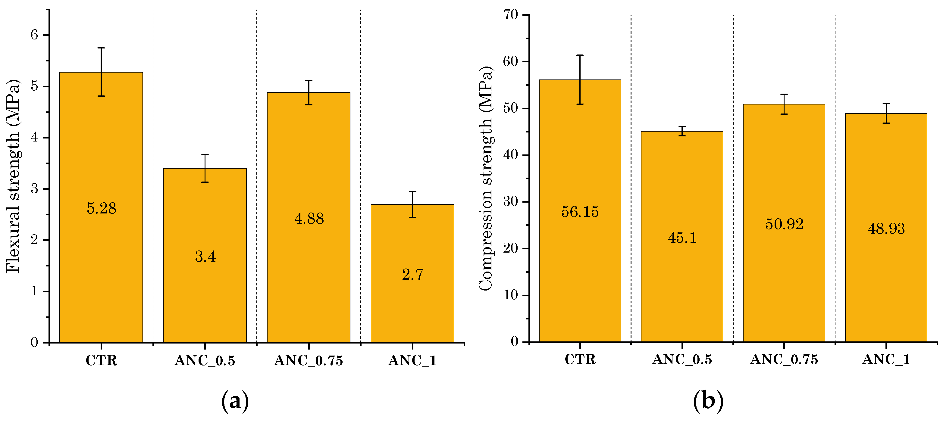
A mechanical performance analysis was also conducted on cementitious mixtures without fibers incorporating ANC to assess whether the addition of the nanoceramic filler had any competitive effect on the strength improvement of the carbon-fiber-reinforced mortars. Flexural and compression strength results are illustrated in Figure 23a,b, respectively. The plots clearly show that the inclusion of ANC adversely affected the strengths of cement mortars. A reduction was clearly observed both in flexural and compression strength for each percentage of nanoclay investigated. Flexural strength was reduced by 35.6%, 7.6%, and 48.9% for the ANC_0.5, ANC_0.75, and ANC_1 mixes, respectively, over the CTR mix. Regarding the compression performance, the strength was reduced by 19.7%, 9.3%, and 12.9% for ANC_0.5, ANC_0.75, and ANC_1 samples, respectively. There are conflicting findings in the literature regarding the effect of nanoclay additions on concrete materials’ performance. Some researchers have verified a slight increase in mechanical strength due to the high pozzolanic reactivity of nanoclay fillers [52,53]. Conversely, some other researchers have shown that to obtain beneficial effects, an adequate dispersion of particles in the cement compound is necessary to avoid agglomeration phenomena, which can inhibit the proper hydration and strength development of the material [25]. The results achieved in this study suggested that the implementation of ANC as a compatibilizer for sCF was an excellent way to maximize the effect of carbon reinforcement on the mechanical strength performance of FRCCs. On the other hand, the possibility of using nanoclay as a pozzolanic filler would require more effective dispersion methods for the proper integration of micro-fibers into the cementitious mixture.

5. Conclusions

This study aimed to explore the potential utilization of sCFs obtained from the industrial production processes of recycled carbon fabrics in FRCC materials. The research focused on implementing an ANC-based conditioning method on the fibers to facilitate the deagglomeration of waste fibrous reinforcements and enhance their compatibility with the cement matrix. The investigation involved the microanalysis of the fibers before and after conditioning with nanoclay, mechanical strength testing through compression, and flexural tests on fiber-reinforced cement mortar samples, as well as microstructural analysis. The following conclusions were drawn from the study:
  • The surface conditioning of sCFs by ANC greatly assists the deagglomeration of fibers, improving their dispersion in the cement matrix. Nanoceramic treatment altered the interfacial surface energy of carbon fiber, enhancing the interface reaction with the hydrophilic medium (cementitious paste).
  • The conditioning method proposed in this study is cost-effective, eco-friendly, and simple, while being extremely successful in enhancing the strength properties of fiber-reinforced mortars. Over a plain mortar mixture (0% sCFs), the maximum increment improvement in flexural and compression strengths was of more than 76% and 13%, respectively. Compared to the mortars incorporating unconditioned sCF, the biggest increase in flexural strength was of more than 100%, demonstrating that the adequate dispersion of fibers was crucial to achieve a significant improvement in mechanical performance. The cement mortar sample that provided the most superior mechanical performance was the sCF-ANC_0.75 mix.
  • Although nanoclay is efficient to prevent the formation of carbon agglomerates and to avoid the presence of defects in the matrix (porosity, partially reacted zones), its effect as a “dry” additive in the mix did not enhance the mechanical strength of cement mixtures. Improper dispersion of this nanomaterial can severely limit its pozzolanic reactivity and therefore performance improvements in the material.
The promising results obtained in this research open up avenues for further characterizations of these cementitious composites, with a focus on evaluating other properties of engineering significance in the realm of fiber-reinforced mortars. This includes conducting impact resistance tests, assessing permeability, evaluating durability, testing shrinkage behavior, and analyzing thermal performance. Expanding the characterization efforts in these areas will provide a more comprehensive understanding of the performance and potential applications of these fiber-reinforced mortars. A limiting factor to be addressed is related to the fiber length variability of sCF, which can alter the final performance of FRCC. Implementing a selection system for the waste fibrous fraction capable of ensuring a more homogeneous size distribution of the fibers would help us move towards a better understanding of the technological characteristics of this material as a concrete reinforcement.

Author Contributions

Conceptualization, M.S. and M.V.; methodology, M.S., S.M.N. and M.C.; validation, M.S., S.M.N. and M.C.; formal analysis, M.S. and S.M.N.; investigation, M.S. and S.M.N.; resources, M.V. and S.H.G.; data curation, M.S., M.V., M.C. and S.H.G.; writing—original draft preparation, M.S.; writing—review and editing, M.S., M.V., M.C. and S.H.G.; supervision, M.V. and S.H.G.; project administration, M.V.; funding acquisition, M.S. and M.V. All authors have read and agreed to the published version of the manuscript.

Funding

This research was supported by the “Avvio alla Ricerca—Tipo 2” funding program provided by Sapienza University of Rome to Dr. Matteo Sambucci. The title of the research project is: Compositi sandwich a matrice cementizia: ottimizzazione delle caratteristiche meccaniche e di isolamento termo-acustico attraverso l’uso di materiali di riciclo derivanti dal recupero di pneumatici a fine vita (no. AR222181627BFECA).

Institutional Review Board Statement

Not applicable.

Informed Consent Statement

Not applicable.

Data Availability Statement

Data will be made available on request.

Acknowledgments

The authors would like to thank Christian Scopinich (Carbon Task Srl) for providing waste carbon fibers implemented in the research activity. The authors also appreciate help from Paola Russo and Sofia Ubaldi for running Fourier-transform infrared spectroscopy tests.

Conflicts of Interest

The authors declare no conflict of interest.

References

  1. Liew, K.M.; Akbar, A. The recent progress of recycled steel fiber reinforced concrete. Constr. Build. Mater. 2020, 232, 117232. [Google Scholar] [CrossRef]
  2. Wang, Y.; Wu, H.C.; Li, V.C. Concrete reinforcement with recycled fibers. J. Mater. Civ. Eng. 2000, 12, 314–319. [Google Scholar] [CrossRef]
  3. Merli, R.; Preziosi, M.; Acampora, A.; Lucchetti, M.C.; Petrucci, E. Recycled fibers in reinforced concrete: A systematic literature review. J. Clean. Prod. 2020, 248, 119207. [Google Scholar] [CrossRef]
  4. Tan, W.L.; Lee, Y.H.; Tan, C.S.; Lee, Y.Y.; Kueh, A.B.H. Mechanical properties and fracture prediction of concretes containing oil palm shell and expanded clay for full replacement of conventional aggregates. J. Teknol. 2022, 84, 171–181. [Google Scholar] [CrossRef]
  5. Lee, Y.H.; Chua, N.; Amran, M.; Lee, Y.Y.; Hong Kueh, A.B.; Fediuk, R.; Vatin, N.; Vasilev, Y. Thermal Performance of Structural Lightweight Concrete Composites for Potential Energy Saving. Crystals 2021, 11, 461. [Google Scholar] [CrossRef]
  6. Kueh, A.B.H.; Razali, A.W.; Lee, Y.Y.; Hamdan, S.; Yakub, I.; Suhaili, N. Acoustical and mechanical characteristics of mortars with pineapple leaf fiber and silica aerogel infills–Measurement and modeling. Mater. Today Commun. 2023, 35, 105540. [Google Scholar] [CrossRef]
  7. Wei, J.; Meyer, C. Degradation mechanisms of natural fiber in the matrix of cement composites. Cem. Concr. Res. 2015, 73, 1–16. [Google Scholar] [CrossRef]
  8. Mukaddas, A.M.; Aziz, F.A.; Nasir, N.M.; Sutan, N.M. Water permeability and chloride and sulphate resistance of rubberised fibre mortar. J. Civ. Eng. Sci. Technol. 2019, 10, 146–157. [Google Scholar] [CrossRef]
  9. Zia, A.; Pu, Z.; Holly, I.; Umar, T.; Tariq, M.A.U.R.; Sufian, M. A Comprehensive Review of Incorporating Steel Fibers of Waste Tires in Cement Composites and Its Applications. Materials 2022, 15, 7420. [Google Scholar] [CrossRef]
  10. Signorini, C.; Volpini, V. Mechanical Performance of Fiber Reinforced Cement Composites Including Fully-Recycled Plastic Fibers. Fibers 2021, 9, 16. [Google Scholar] [CrossRef]
  11. Małek, M.; Jackowski, M.; Łasica, W.; Kadela, M.; Wachowski, M. Mechanical and Material Properties of Mortar Reinforced with Glass Fiber: An Experimental Study. Materials 2021, 14, 698. [Google Scholar] [CrossRef] [PubMed]
  12. Singh, A.; Charak, A.; Biligiri, K.P.; Pandurangan, V. Glass and carbon fiber reinforced polymer composite wastes in pervious concrete: Material characterization and lifecycle assessment. Resour. Conserv. Recycl. 2022, 182, 106304. [Google Scholar] [CrossRef]
  13. Sakai, A.; Kurniawan, W.; Kubouchi, M. Recycled Carbon Fibers with Improved Physical Properties Recovered from CFRP by Nitric Acid. Appl. Sci. 2023, 13, 3957. [Google Scholar] [CrossRef]
  14. Ren, Y.; Xu, L.; Shang, X.; Shen, Z.; Fu, R.; Li, W.; Guo, L. Evaluation of mechanical properties and pyrolysis products of carbon fibers recycled by microwave pyrolysis. ACS Omega 2022, 7, 13529–13537. [Google Scholar] [CrossRef]
  15. Holmes, M. Recycled carbon fiber composites become a reality. Reinf. Plast. 2018, 62, 148–153. [Google Scholar] [CrossRef]
  16. Akbar, A.; Kodur, V.K.R.; Liew, K.M. Microstructural changes and mechanical performance of cement composites reinforced with recycled carbon fibers. Cem. Concr. Compos. 2021, 121, 104069. [Google Scholar] [CrossRef]
  17. Kimm, M.; Sabir, A.; Gries, T.; Suwanpinij, P. Potential of Using Recycled Carbon Fibers as Reinforcing Material for Fiber Concrete. In Fibre Reinforced Concrete: Improvements and Innovations; BEFIB, 2020; RILEM, Bookseries; Serna, P., Llano-Torre, A., Martí-Vargas, J.R., Navarro-Gregori, J., Eds.; Springer: Cham, Switzerland, 2021; Volume 30. [Google Scholar] [CrossRef]
  18. Li, Y.-F.; Li, J.-Y.; Ramanathan, G.K.; Chang, S.-M.; Shen, M.-Y.; Tsai, Y.-K.; Huang, C.-H. An Experimental Study on Mechanical Behaviors of Carbon Fiber and Microwave-Assisted Pyrolysis Recycled Carbon Fiber-Reinforced Concrete. Sustainability 2021, 13, 6829. [Google Scholar] [CrossRef]
  19. Xiong, C.; Li, Q.; Lan, T.; Li, H.; Long, W.; Xing, F. Sustainable use of recycled carbon fiber reinforced polymer and crumb rubber in concrete: Mechanical properties and ecological evaluation. J. Clean. Prod. 2021, 279, 123624. [Google Scholar] [CrossRef]
  20. Sambucci, M.; Valente, M. Ground Waste Tire Rubber as a Total Replacement of Natural Aggregates in Concrete Mixes: Application for Lightweight Paving Blocks. Materials 2021, 14, 7493. [Google Scholar] [CrossRef]
  21. Boudriche, L.; Calvet, R.; Hamdi, B.; Balard, H. Effect of acid treatment on surface properties evolution of attapulgite clay: An application of inverse gas chromatography. Colloids Surf. A Physicochem. Eng. Asp. 2011, 392, 45–54. [Google Scholar] [CrossRef]
  22. Liu, J.; Zhong, J.; Chen, Z.; Mao, J.; Liu, J.; Zhang, Z.; Li, X.; Ren, S. Preparation, characterization, application and structure evolution of attapulgite: From nanorods to nanosheets. Appl. Surf. Sci. 2021, 565, 150398. [Google Scholar] [CrossRef]
  23. Mohammad Mehdipour, N.; Reddy, N.; Shor, R.J.; Natale, G. Orientation dynamics of anisotropic and polydisperse colloidal suspensions. Phys. Fluids 2022, 34, 083317. [Google Scholar] [CrossRef]
  24. Hakamy, A.; Shaikh, F.U.A.; Low, I.M. Effect of calcined nanoclay on microstructural and mechanical properties of chemically treated hemp fabric-reinforced cement nanocomposites. Constr. Build. Mater. 2015, 95, 882–891. [Google Scholar] [CrossRef]
  25. Niu, X.J.; Li, Q.B.; Hu, Y.; Tan, Y.S.; Liu, C.F. Properties of cement-based materials incorporating nano-clay and calcined nano-clay: A review. Constr. Build. Mater. 2021, 284, 122820. [Google Scholar] [CrossRef]
  26. El-Seidy, E.; Chougan, M.; Sambucci, M.; Al-Kheetan, M.J.; Biblioteca, I.; Valente, M.; Ghaffar, S.H. Lightweight alkali-activated materials and ordinary Portland cement composites using recycled polyvinyl chloride and waste glass aggregates to fully replace natural sand. Constr. Build. Mater. 2023, 368, 130399. [Google Scholar] [CrossRef]
  27. Chougan, M.; Ghaffar, S.H.; Sikora, P.; Mijowska, E.; Kukułka, W.; Stephan, D.; Albar, A.; Swash, M.R. Boosting Portland cement-free composite performance via alkali-activation and reinforcement with pre-treated functionalised wheat straw. Ind. Crops Prod. 2022, 178, 114648. [Google Scholar] [CrossRef]
  28. Snoeck, D.; Schaubroeck, D.; Dubruel, P.; De Belie, N. Effect of high amounts of superabsorbent polymers and additional water on the workability, microstructure and strength of mortars with a water-to-cement ratio of 0.50. Constr. Build. Mater. 2014, 72, 148–157. [Google Scholar] [CrossRef]
  29. ASTM C348-02; American Society for Testing and Materials. Flexural Strength of Hydraulic-Cement Mortars. ASTM International: West Conshohocken, PA, USA, 2002; pp. 1–6.
  30. ASTM C109/C109M-02; American Society for Testing and Materials. Standard Test Method for Compressive Strength of Hydraulic Cement Mortars (Using 2-in. or Cube Specimens). ASTM International: West Conshohocken, PA, USA, 2016; pp. 1–10.
  31. Quigley, J.P.; Herrington, K.; Bortner, M.; Baird, D.G. Benign reduction of carbon nanotube agglomerates using a supercritical carbon dioxide process. Appl. Phys. A 2014, 117, 1003–1017. [Google Scholar] [CrossRef]
  32. Chuang, W.; Lei, P.; Bing-Liang, L.; Ni, G.; Li-Ping, Z.; Ke-Zhi, L. Influences of molding processes and different dispersants on the dispersion of chopped carbon fibers in cement matrix. Heliyon 2018, 4, e00868. [Google Scholar] [CrossRef]
  33. Zabihi, O.; Ahmadi, M.; Li, Q.; Shafei, S.; Huson, M.G.; Naebe, M. Carbon fibre surface modification using functionalized nanoclay: A hierarchical interphase for fibre-reinforced polymer composites. Compos. Sci. Technol. 2017, 148, 49–58. [Google Scholar] [CrossRef]
  34. Jeong, H.K.; Lee, Y.P.; Jin, M.H.; Kim, E.S.; Bae, J.J.; Lee, Y.H. Thermal stability of graphite oxide. Chem. Phys. Lett. 2009, 470, 255–258. [Google Scholar] [CrossRef]
  35. Zawrah, M.F.; Khattab, R.M.; Saad, E.M.; Gado, R.A. Effect of surfactant types and their concentration on the structural characteristics of nanoclay. Spectrochim. Acta Part A Mol. Biomol. Spectrosc. 2014, 122, 616–623. [Google Scholar] [CrossRef] [PubMed]
  36. Liao, L.; Li, X.; Wang, Y.; Fu, H.; Li, Y. Effects of surface structure and morphology of nanoclays on the properties of jatropha curcas oil-based waterborne polyurethane/clay nanocomposites. Ind. Eng. Chem. Res. 2016, 55, 11689–11699. [Google Scholar] [CrossRef]
  37. Rath, J.P.; Chaki, T.K.; Khastgir, D. Development of natural rubber-fibrous nano clay attapulgite composites: The effect of chemical treatment of filler on mechanical and dynamic mechanical properties of composites. Procedia Chem. 2012, 4, 131–137. [Google Scholar] [CrossRef]
  38. Zhu, H.; Zhou, H.; Gou, H. Evaluation of carbon fiber dispersion in cement-based materials using mechanical properties, conductivity, mass variation coefficient, and microstructure. Constr. Build. Mater. 2021, 266, 120891. [Google Scholar] [CrossRef]
  39. Li, Y.; Zhang, J.; He, Y.; Huang, G.; Li, J.; Niu, Z.; Gao, B. A review on durability of basalt fiber reinforced concrete. Compos. Sci. Technol. 2022, 225, 109519. [Google Scholar] [CrossRef]
  40. Mobili, A.; Giosuè, C.; Bellezze, T.; Revel, G.M.; Tittarelli, F. Gasification Char and Used Foundry Sand as Alternative Fillers to Graphene Nanoplatelets for Electrically Conductive Mortars with and without Virgin/Recycled Carbon Fibres. Appl. Sci. 2021, 11, 50. [Google Scholar] [CrossRef]
  41. Lu, M.; Xiao, H.; Liu, M.; Feng, J. Carbon fiber surface nano-modification and enhanced mechanical properties of fiber reinforced cementitious composites. Constr. Build. Mater. 2023, 370, 130701. [Google Scholar] [CrossRef]
  42. Belli, A.; Mobili, A.; Bellezze, T.; Tittarelli, F. Commercial and recycled carbon/steel fibers for fiber-reinforced cement mortars with high electrical conductivity. Cem. Concr. Compos. 2020, 109, 103569. [Google Scholar] [CrossRef]
  43. Raza, S.S.; Fahad, M.; Ali, B.; Amir, M.T.; Alashker, Y.; Elhag, A.B. Enhancing the Performance of Recycled Aggregate Concrete Using Micro-Carbon Fiber and Secondary Binding Material. Sustainability 2022, 14, 14613. [Google Scholar] [CrossRef]
  44. Chen, P.W.; Chung, D.D.L. Low-drying-shrinkage concrete containing carbon fibers. Compos. Part B Eng. 1996, 27, 269–274. [Google Scholar] [CrossRef]
  45. Baeza, F.J.; Galao, O.; Zornoza, E.; Garcés, P. Effect of aspect ratio on strain sensing capacity of carbon fiber reinforced cement composites. Mater. Des. 2013, 51, 1085–1094. [Google Scholar] [CrossRef]
  46. Mallick, P.K. Fiber-reinforced composites: Materials, manufacturing, and design. In Manufacturing and Design; Marcel Dekker Inc.: New York, NY, USA, 2007. [Google Scholar]
  47. Alaskar, A.; Albidah, A.; Alqarni, A.S.; Alyousef, R.; Mohammadhosseini, H. Performance evaluation of high-strength concrete reinforced with basalt fibers exposed to elevated temperatures. J. Build. Eng. 2021, 35, 102108. [Google Scholar] [CrossRef]
  48. Wu, H.; Pan, J.; Wang, J. Molecular dynamics simulation study on dynamic mechanical properties of CSH with diverse Ca/Si ratios. Mater. Today Commun. 2022, 31, 103755. [Google Scholar] [CrossRef]
  49. Yan, X.; Zheng, D.; Yang, H.; Cui, H.; Monasterio, M.; Lo, Y. Study of optimizing graphene oxide dispersion and properties of the resulting cement mortars. Constr. Build. Mater. 2020, 257, 119477. [Google Scholar] [CrossRef]
  50. O’Neil, E.F., III; Cummins, T.K.; Durst, B.P.; Kinnebrew, P.G.; Boone, R.N.; Torres, R.X. Development of very-high-strength and high-performance concrete materials for improvement of barriers against blast and projectile penetration. Transform. Sci. Technol. Curr. Future Force 2006, 203–210. [Google Scholar] [CrossRef]
  51. Liu, B.; Guo, J.; Zhou, J.; Wen, X.; Deng, Z.; Wang, H.; Zhang, X. The mechanical properties and microstructure of carbon fibers reinforced coral concrete. Constr. Build. Mater. 2020, 249, 118771. [Google Scholar] [CrossRef]
  52. Hamed, N.; El-Feky, M.S.; Kohail, M.; Nasr, E.S.A. Effect of nano-clay de-agglomeration on mechanical properties of concrete. Constr. Build. Mater. 2019, 205, 245–256. [Google Scholar] [CrossRef]
  53. Mansi, A.; Sor, N.H.; Hilal, N.; Qaidi, S.M. The impact of nano clay on normal and high-performance concrete characteristics: A review. IOP Conf. Ser. Earth Environ. Sci. 2022, 961, 012085. [Google Scholar] [CrossRef]
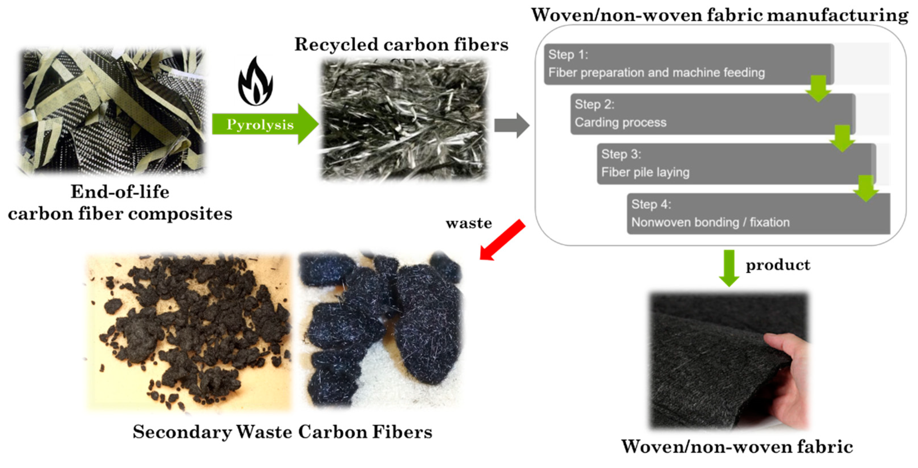
Figure 1. Flowchart of the process leading to the production of sCFs used in this work.
Coatings 13 01466 g001
Figure 2. SEM micrographs of an sCF agglomerate at different magnifications: (a) 250× and (b) 6.25 k×.
Coatings 13 01466 g002
Figure 3. Image-processing analysis for measuring the average diameter of sCF.
Coatings 13 01466 g003
Figure 4. (a) Appearance of ANC and (b) microstructural characteristics by SEM in dry powder form.
Coatings 13 01466 g004
Figure 5. EDS spectrum of ANC.
Coatings 13 01466 g005
Figure 6. Schematic of ANC crystal structure. Reprinted with permission from Ref. [21]. Copyright 2011, Elsevier.
Coatings 13 01466 g006
Figure 7. DLS size distribution profile of ANC.
Coatings 13 01466 g007
Figure 8. Conditioning sCFs via nanoceramic slurry: (a) weighing the carbon fibers, (b) ANC addition, (c) stirring the ANC-based slurry with sCFs, and (d) appearance of the ceramic slurry sample after oven-drying for microanalysis on post-conditioned sCFs.
Coatings 13 01466 g008
Figure 9. Treatment of sCFs via magnetic stirring in water without addition of ANC: (a) sCFs–water mixing, (b) filtration of the mixture after treatment, and (c) appearance of the filtrated mixture.
Coatings 13 01466 g009
Figure 10. Schematic drawing of the interaction between sCF and ANC in accordance with the mechanism proposed by Zabihi et al. [33].
Coatings 13 01466 g010
Figure 11. SEM analysis of sCFs after conditioning with ANC.
Coatings 13 01466 g011
Figure 12. EDS spectrum of sCFs after conditioning with ANC.
Coatings 13 01466 g012
Figure 13. FT-IR spectrum of bare sCF (black plot), ANC (orange plot), and sCF conditioned with ANC (blue plot).
Coatings 13 01466 g013
Figure 14. Flexural strength test results for sCF-reinforced cement mortars in comparison to unconditioned sCF and control samples.
Coatings 13 01466 g014
Figure 15. Fractographies of the specimens after flexural test. Yellow arrows indicate sCF agglomerates into the matrix.
Coatings 13 01466 g015aCoatings 13 01466 g015b
Figure 16. Percentages of increase in flexural strength of FRCCs with vCFs and rCFs reported in 6 articles (Refs. [16,17,18,42,43,44]) and comparison with the results achieved in the present work using sCFs.
Coatings 13 01466 g016
Figure 17. Compression strength test results for sCF-reinforced cement mortars.
Coatings 13 01466 g017
Figure 18. (a) Load–strain behavior (CTR, sCF_0.5, and sCF-ANC_0.5 samples) and (b) relative elastic modulus of sCF-reinforced mortars.
Coatings 13 01466 g018
Figure 19. SEM microstructural analysis of FRCCs adding unconditioned sCFs: (a) clusters of sCF interspersed into the matrix and (b) cement paste trapped within the carbon agglomerates.
Coatings 13 01466 g019
Figure 20. EDS spectra of the cementitious phase entrapped within the sCF agglomerates (a) and the bulk cement matrix (b).
Coatings 13 01466 g020
Figure 21. SEM microstructural analysis of FRCCs with sCFs added after conditioning with ANC: (a) microstructure of the mortar and (b) detail of carbon fibers dispersed and isolated within the matrix.
Coatings 13 01466 g021
Figure 22. SEM microstructural analysis of ITZ between sCFs after conditioning with ANC and cement matrix: (a) cracking and fiber pull out and (b) detail on microcracks propagation around the fiber.
Coatings 13 01466 g022
Figure 23. Mechanical test results of ANC group samples: (a) flexural strength and (b) compression strength.
Coatings 13 01466 g023
Table 1. Quantitative EDS chemical elemental analysis of ANC.
ElementAtomic %
Ca0.63
O58.25
Mg6.65
Al4.58
Si29.23
Au0.66
Table 2. Mix proportions.
GroupCement (kg/m3)Sand
(kg/m3)
Water (kg/m3)sCF
(kg/m3)
ANC
(kg/m3)
CTR7001170295--
sCF_0.570011702953.5-
sCF_0.7570011702955.25-
sCF_170011702957-
sCF-ANC_0.570011702973.53.5
sCF-ANC_0.7570011702985.255.25
sCF-ANC_1700117030077
ANC_0.57001170297-3.5
ANC_0.757001170298-5.25
ANC_17001170300-7
Table 3. Quantitative EDS chemical elemental analysis of sCF after conditioning with ANC.
ElementAtomic %
C86.69
O7.91
Mg0.96
Al0.66
Si2.65
Au1.13
Table 4. Ca/Si ratio evaluated from EDS. (The results refer to average value from four-point-scan analysis on the investigated area).
AreaCa (Atomic %)Si (Atomic %)Ca/Si Ratio
Cement embedded in sCF (a)27.4012.132.26
Bulk cement matrix (b)64.8816.443.95
Disclaimer/Publisher’s Note: The statements, opinions and data contained in all publications are solely those of the individual author(s) and contributor(s) and not of MDPI and/or the editor(s). MDPI and/or the editor(s) disclaim responsibility for any injury to people or property resulting from any ideas, methods, instructions or products referred to in the content.