Article

Geometric Structures for Sialon Ceramic Solid End Mills and Its Performance in High-Speed Milling of Nickel-Based Superalloys

1
Centre for Advanced Jet Engineering Technologies (CaJET), School of Mechanical Engineering, Shandong University, Jinan 250061, China
2
Key Laboratory of High Efficiency and Clean Mechanical Manufacture, Shandong University, Ministry of Education, Jinan 250061, China
3
National Demonstration Center for Experimental Mechanical Engineering Education, Shandong University, Jinan 250061, China
4
Additive Manufacturing Research Center of Shandong University of National Engineering Research Center of Rapid Manufacturing, Shandong University, Jinan 250061, China
*
Authors to whom correspondence should be addressed.
Coatings 2023, 13(9), 1483; https://doi.org/10.3390/coatings13091483
Submission received: 23 July 2023 / Revised: 16 August 2023 / Accepted: 21 August 2023 / Published: 22 August 2023

Abstract

:
Sialon ceramic tool material has become one of the most ideal materials for the high-speed cutting of superalloy materials. However, studies on the geometric structure of sialon ceramic solid end mill is lacking at the present. In this work, the geometric structure of sialon ceramic end mills was designed for difficult-to-machine nickel-based superalloy materials. The cutting force and heat, flank wear and machined surface quality were analyzed to study the effect of the main parameters on tool performance. The results showed that the end mill experienced severe flank wear and chipping, which were the leading cause of its failure during high-speed cutting. The cutting force and temperature decreased gradually with the increase in the helix angle. With the increase in the rake angle, the flank wear and the quality of the machined surface of the specimen first decreased and then increased. With the increase in the relief angle, the cutting temperature of the ceramic end mill gradually decreased, and the cutting force and the machined surface roughness showed an initial decrease and then increased. When the helix angle, rake angle and relief angle were 35°, −15° and 12°, respectively, the sialon ceramic end mill exhibited the best cutting performance and obtained better machined surface quality in the nickel-based superalloys.

1. Introduction

Nickel-based superalloys (GH4099) are an ideal candidate for critical components in aerospace and gas turbines due to their excellent physical and chemical properties at high temperatures (800 °C) [1,2]. In the cutting process of nickel-based superalloys, due to the high-temperature strength, poor thermal conductivity and high toughness of nickel-based superalloys, high cutting force and cutting heat are generated, resulting in serious tool wear and chipping. Therefore, nickel-based superalloys are classified as difficult-to-machine materials due to their low processing quality and efficiency [3,4]. With the rapid development of aerospace and gas turbines, the quality and demand for nickel-based superalloy parts have increased. Because nickel-based superalloys are difficult-to-machine materials, cutting tool materials should meet certain mechanical properties, including high red hardness, thermochemical stability, and excellent thermal shock resistance [5]. Currently, the cutting tool materials used to process nickel-based superalloys include cemented carbide, ceramics and cubic boron nitride [6]. Cemented carbide tools are commonly used for the low-speed machining of nickel-based superalloys with low machining efficiency. When the machining parameters were raised, cemented carbide tools are prone to wear and chipping during machining [7,8]. Although the coating improves the machining efficiency of cemented carbide tools, the machining efficiency and tool life are still low when cutting nickel-based superalloys [9,10,11,12]. Cubic boron nitride tools have the disadvantages of a complex manufacturing process and high cost, which limits its application in the market [13].
Ceramic tool materials have higher hardness and wear resistance, excellent heat resistance and oxidation resistance compared to cemented carbide tool materials, as well as favorable high-temperature performance, which have tremendous advantages in the high-speed cutting of difficult-to-machine materials and is widely used in dry cutting, high-speed cutting and other machining fields [14,15]. Currently, there are three types of ceramic tool materials: alumina-based ceramics, silicon nitride-based ceramics and Sialon ceramics. Sialon ceramics are solid solutions of Al2O3 and Si3N4 and combine the characteristics of Al2O3 and Si3N4 ceramic materials, which have excellent thermal shock resistance, chemical stability and low coefficient of thermal expansion [16,17]. But, during the high-speed cutting of nickel-based superalloys, the high cutting temperature of Sialon ceramic tool flank, cutting force and impact force are generated due to their difficult machinability [18]. Li et al. measured the cutting forces of Sialon ceramic tools for the high-speed milling (vc = 500 m/min) of GH4169 superalloy and found that the cutting forces reached more than 1200 N [19]. Zheng et al. discovered that the cutting forces of ceramic tools cutting Inconel 718 decreased and then increased in the cutting speed range of 500–1600 m/min, of which the average cutting forces were measured at above 1800 N [20]. Ceramic tools are subject to severe wear and breakage due to the heavy cutting forces during the high-speed milling of nickel-based superalloys [21,22]. Sun et al. conducted end milling experiments on nickel-based superalloy GH4099 using Sialon ceramic tools and found that adhesive, diffusive, abrasive, and chemical wear were the dominant forms of tool wear and their cutting efficiency was well above that of cemented carbide tools [23]. Ma et al. has milled Inconel 718 using Sialon and TiC whisker toughened Si3N4 ceramic end mills at cutting speeds of 200–350 m/min. It was found that Sialon ceramic tools had superior wear resistance but poor machined surface quality, while Si3N4 ceramic tools had the opposite [24]. In addition, brittle fracture was the primary form of wear for both ceramic tool materials. The Sialon ceramic tool was spalling off the cutting edge, and Si3N4 ceramic tool was severely worn by spalling of the flank. Cslik et al. studied the wear mechanism of Inconel 718 by high-speed milling using Sialon ceramic end mills. The results showed that the main wear types were adhesion and diffusion wear [25]. Tian et al. characterized the wear characteristics of Sialon ceramic tools when machining Inconel 718 at cutting speeds of 600–3000 m/min and discovered that notch wear was primarily occurring at lower cutting speeds (600–1000 m/min), while flank wear was the dominant form when cutting speeds exceeded 1400 m/min [26]. Furthermore, ceramic tools have various degrees of breakage, such as chipping, flaking, and fracture, while cutting nickel-based superalloys at high speeds [25,27,28].
Although ceramic tools have been applied to the high-speed cutting of nickel-based superalloys, severe tool wear during machining is one of the main reasons limiting their development. Current research on ceramic end mills for the high-speed cutting of superalloys focuses on cutting performance, tool wear and failure mechanisms. In contrast, more research needs to be conducted on the geometric structure of ceramic end mills. Therefore, this work studies the influence of the geometric structure of the ceramic end mill on the cutting performance of the ceramic end mill for machining nickel-based superalloy, taking the cutting force, cutting temperature, flank wear and surface roughness as the evaluation indexes. In addition, this study designed a ceramic end mill structure suitable for the high-speed cutting of nickel-based superalloys to reduce tool wear failure, improve processing quality and efficiency, and achieve efficient and clean machining of ceramic end mills.

2. Experiment

2.1. Workpiece and Ceramic Tools

In this study, the workpiece material was the nickel-based superalloy GH4099 prepared by solution and aging heat treatment, which was cut into rectangular experimental blocks with dimensions of 100 mm × 40 mm × 60 mm by wire electrical discharge machining. The elemental composition and physical properties of the GH4099 superalloy are shown in Table 1 and Table 2.
Self-designed and ground Sialon ceramic end mills were employed in this study, and the tool material contains Si, N, O and Al elements identified by EDS analysis, as shown in Figure 1. In addition, the mechanical properties of the ceramic end mill employed are provided in Table 3, which shows that the high hardness as well as excellent flexural strength and fracture toughness enable it to satisfy the requirements of the high-speed milling of nickel-based superalloys. It has been reported that the reasonable selection of the end mill’s helix angle, rake angle and relief angle could enhance the strength of cutting edge, reduce the cutting force and temperature, thereby improving the end mill life [29,30,31]. Therefore, the aim of this study was to optimize the structure of these three parameters. Meanwhile, the research conducted by our group in the early stage showed that the ceramic end mills had excellent cutting performance when the helix angle, rake angle and relief angle were 40°, −15°and−12°, respectively [12]. In this study, three values of helix angle, rake angle and relief angle were selected for optimization experiments on this basis, and they were numbered SZ-1 to SZ-7, respectively. Table 4 displays the specific geometric parameters of the designed Sialon ceramic end mills.

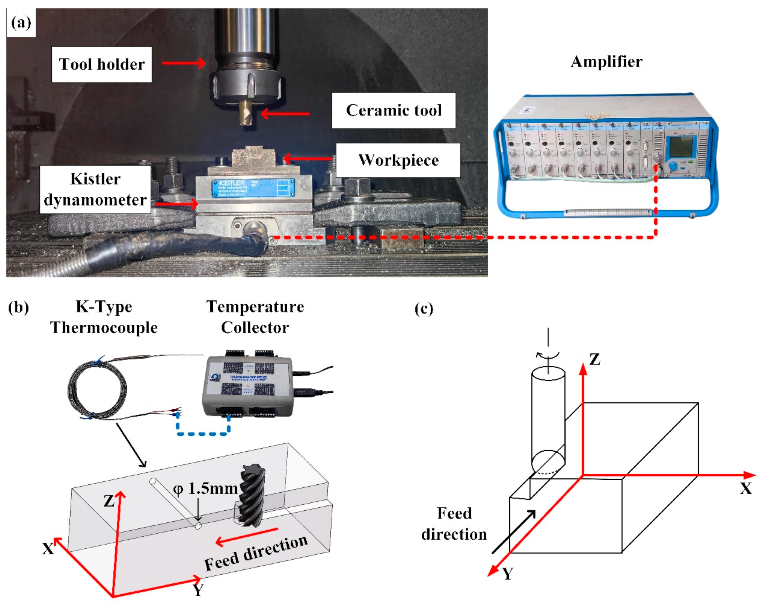
2.2. Milling Scheme and Experimental Setup

The experiments were conducted on the DMU-70V five-axis CNC machining center, whose spindle speed can reach 18,000 rpm, completely satisfying the high-speed milling requirements of the experiments. As shown in Figure 2a, the dynamometer was fixed to the machine table using a fixture, which was connected to the 5080A charge amplifier and data acquisition system, which was the dynamic force measurement system used to record the cutting force signal during the milling process. In the milling experiment, the force signal sampling frequency was 20,000 Hz. Moreover, the cutting force data were recorded every 0.2 m of the end mill cutting until the milling distance was 4 m, after which when the experiment was stopped. Averaged forces during milling were adopted to evaluate the cutting performance of ceramic end mills since the cutting force was a cyclically varying force, which was calculated by extracting the isotropic cutting force during the stable phase of milling using Equation (1). Furthermore, the cutting combined force can intuitively reflect the wear degree of the ceramic tool in the milling process, so it is adopted as an evaluation index of the cutting performance of ceramic tools, which is expressed by the calculation of Equation (2).
F x = 1 N i = 1 N F x i ,   F y = 1 N i = 1 N F y i ,   F z = 1 N i = 1 N F z i
F = F x 2 + F y 2 + F z 2
where N is the number of recorded data points; and Fx, Fy and Fz are the average cutting forces in the X, Y and Z directions, respectively.
As shown in Figure 2b, the thermocouple was connected to the USB data collector with cold-end compensation to collect the cutting temperature data. The thermocouple used was a K-type thermocouple (ERNK-191) with a probe length of 100 mm and a diameter of 1.5 mm, which can measure the temperature of −129 °C to 1300 °C with a relative error of about 1.2 °C. A through-hole of 1.5 mm was carved out of the workpiece using the wire electrical discharge machining, and the thermocouple probe was fixed in the workpiece through-hole by an interference fit. The sampling frequency was 500 Hz, and the data collector started measuring the cutting temperature at the cutting edge when the ceramic end mill reached the position of the thermocouple sensing probe until the thermocouple sensing probe was cut off. At the same time, a high-temperature conductive paste was applied to the working area of the thermocouple sensing probe to avoid rapid dissipation of the cutting temperature.
The dry down milling method was adopted in this experiment, and the schematic diagram is shown in Figure 2c. Moreover, ceramic end mills had favorable cutting performance when the milling parameters shown in Table 5 were applied in the previous studies of this group, so this parameter continued to be applied for the study. A handheld microscope (Dino-lite, edge 3.0) (AnMo Electronics Corporation, New Taipei, Taiwan) was utilized to measure the VB value of the wear on the flank of the ceramic end mill. The end mill flank was photographed at every 0.2 m milling to observe whether the tool’s cutting edge was chipping significantly, while in the case of no chipping, the flank wear area was measured. The machined surface roughness of the workpiece at each 1 m was measured by a laser scanning microscope.

3. Results and Discussions

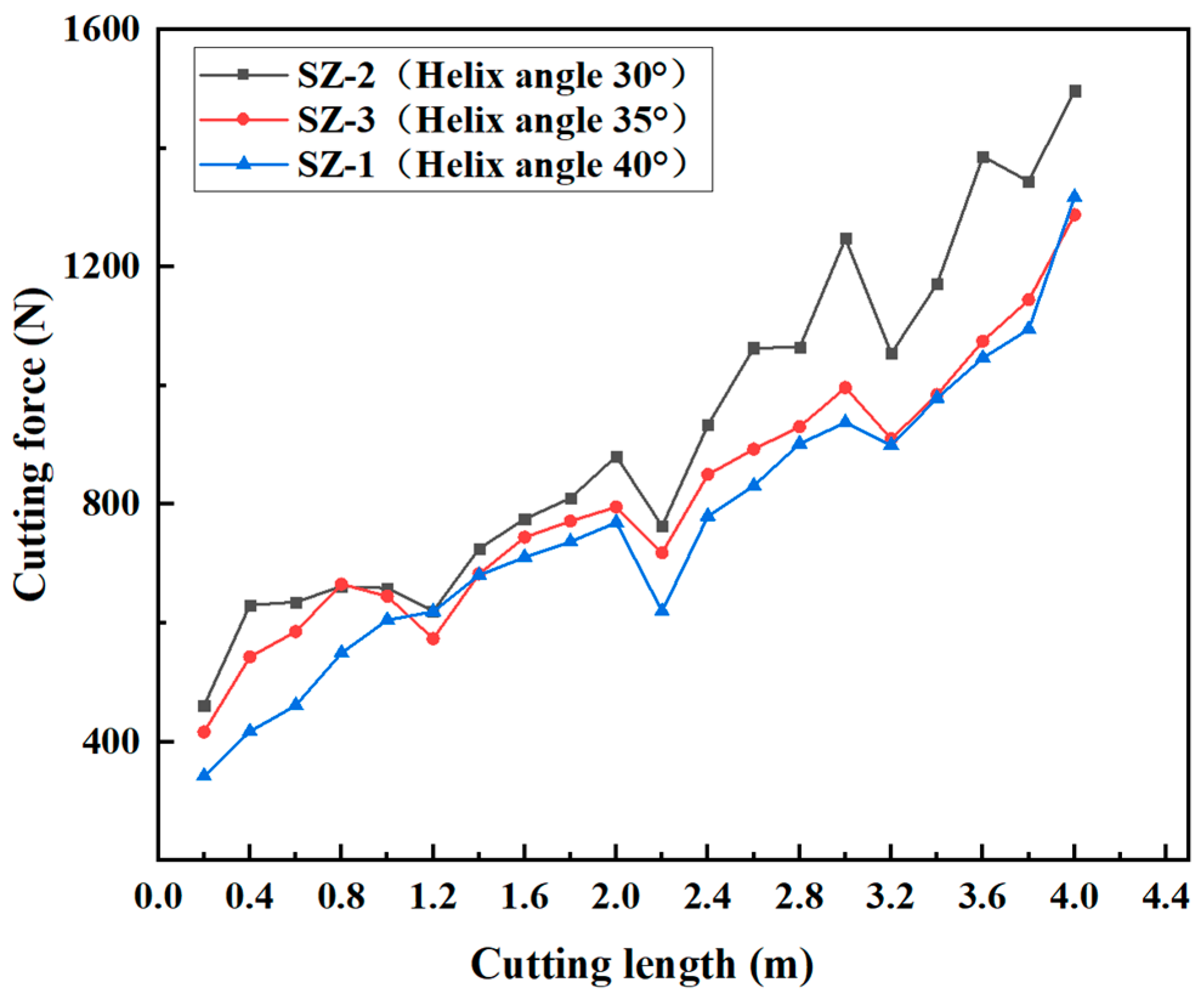
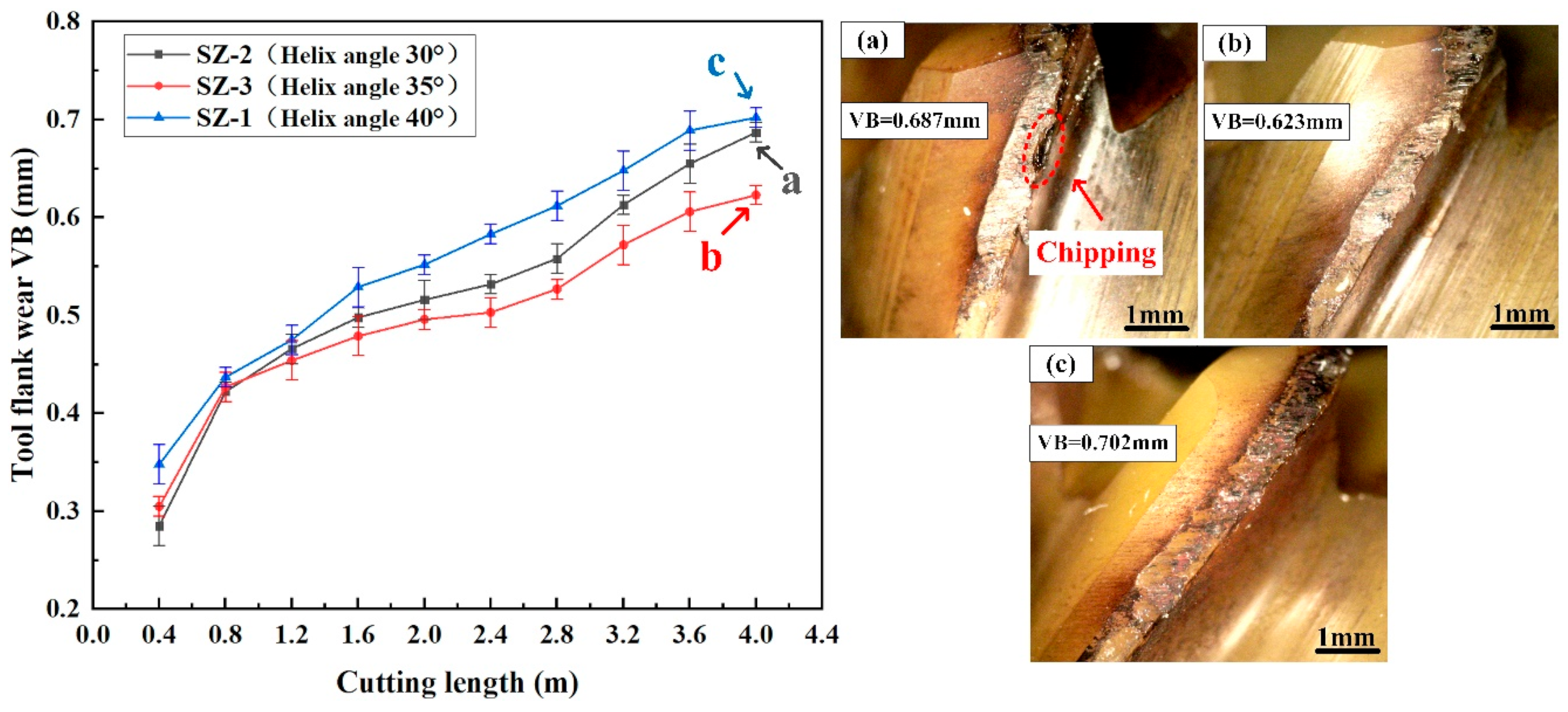
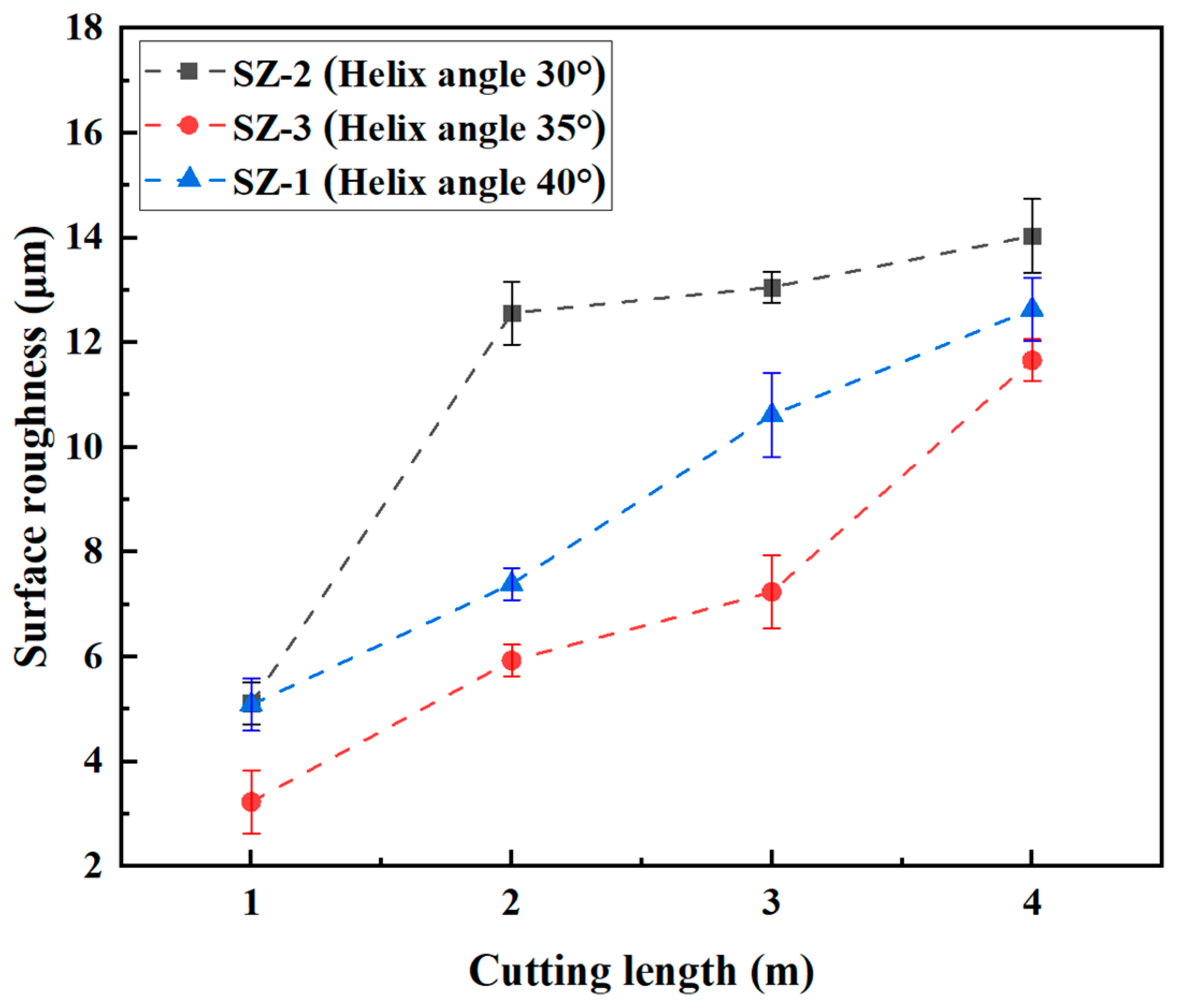
3.1. Effect of Helix Angle on the Cutting Performance of Sialon Ceramic End Mills

It can be observed in Figure 3 that the cutting force decreased as the helix angle increased. When the helix angle of the ceramic end mill was 30°, the cutting force had a large increase. But, the variation of cutting forces was not significant when the helix angle increased from 35° to 40°. The cutting forces of the two end mills were reduced by 2.3% and 2.2% when machining up to 4 m compared to the 30° helix angle when the helix angles of ceramic end mill were 35° and 40°. There are two reasons for the decrease in cutting force as the of helix angle increases. Firstly, increasing the helix angle leads to a larger actual working rake angle of the end mill, which improves the sharpness of the cutting edge, making cutting lighter and faster while ensuring the strength of the cutting edge remains unchanged. The increase in the helix angle is beneficial to the discharge of the chip, reducing the friction between the chip and the rake face of the tool, so that the cutting force becomes smaller. Secondly, With the increase in the helix angle, the flank wear of the tool decreases first and then increases, and it is the smallest when the helix angle is 35° in Figure 4. The reduction of tool side wear leads to a decrease in friction, thereby reducing the cutting force. When the ceramic end mill with a helix angle of 30° is machined for 4 m, the side VB reaches 0.687 mm, and chips appear on the cutting edge, resulting in an increase in cutting force. When the helix angle is 40°, the flank wear of the ceramic end mill is serious, but the cutting force is similar to that of the ceramic end mill with a helix angle of 35° owing to the variation in cutting temperature [27]. As the helix angle increased, the cutting temperature gradually decreased, which followed the same trend as the cutting force in Figure 5 [29]. Meanwhile, the chip removal performance of ceramic end mills is improved due to the increased helix angle, resulting in increased heat carried by the chips. With increased helix angle from 30° to 40°, the cutting temperatures were 1183 °C, 1139 °C and 1092 °C, respectively. The γ′ phase in the nickel-based superalloy began to dissolve at 1120 °C, which reduced the strength of the workpiece material due to the thermal softening effect of the workpiece. Therefore, the cutting force decreased owing to the low strength of the workpiece material at higher cutting temperatures [32,33]. However, when the helix angle is 40°, the workpiece will not undergo thermal softening during milling due to the low cutting temperature, which led to the increase in cutting force and wear.
It was observed in Figure 6 that the surface roughness was the minimum value when the helix angle was 35°, and the surface roughness was the maximum when the helix angle was 30°, which was consistent with the trend of the flank wear in Figure 7. The surface roughness rose smoothly when the helix angle was 35° and 40°, while it increased suddenly at a cutting distance of 2 m when the helix angle was 30° and then tended to rise slowly and smoothly. This is attributed to the change of the shape of the tool’s cutting edge. From the cutting force analysis, there was also a sudden increase in the cutting force of the ceramic end mill with a helix angle of 30° when the cutting distance was 2 m. The workpiece material cannot be completely removed, and the surface roughness increases suddenly due to the edge breakage of the tool at this stage. Additionally, the surface roughness rose when the helix angle was 40° because of the more extensive wear on its flank and the severe friction between the tool flank and the surface of workpiece.
The 3D morphology of the machined surface is shown in Figure 7(a1–c1) for when the workpiece was machined by three kinds of ceramic end mills for 1 m. It can be observed from the chip morphology in the feed direction that this is an obvious extrusion mode, which was caused by side and chip extrusion. Due to the high temperature and cutting forces in the high-speed milling process, the chip was cold welded to the ceramic end mill cutting edge under the action of high temperature and pressure, which would be covered with the ceramic end mill base, forming a chip layer. Such a chip layer enhanced the affinity between the ceramic end mill and the workpiece, and the sticky chips on the cutting edge gradually increased with the cutting distance [27,34]. The chip layer peeled off the ceramic end mill surface under strong alternating friction and impact loads. The exposed ceramic end mill substrate was re-adhered to the new chip layer after several cutting cycles. In the chip layer of the periodic adhesion and peeling process, the workpiece machining surface of the sticky chip increased. There was a clear peak along the feed direction, which indicated that a small notch in the cutting edge already appeared at 1 m of cutting in Figure 7(a1). The workpiece material could not be removed entirely and formed a peak at this parallel position. The 3D morphology of the machined surface at a cutting distance of 4 m is shown in Figure 7(a2–c2). Many scale spurs were produced perpendicular to the feed direction and formed peaks and valleys when the helix angle of the ceramic end mills was 30° and 40°, which was caused by severe tool wear. Since the rake angle of the ceramic end mill designed in this paper was negative, the workpiece material was removed by the squeezing effect of the rake face of the tool. And the severe tool wear caused the rounding angle of the cutting edge to become more prominent. Therefore, when the cutting edge removed the workpiece material, a part of the material would flow from the blunt corner to the flank under the extrusion of the rake face, which formed a scale spur after the extrusion of the flank. Due to the severe wear of the tool, the cutting temperature increases, resulting in an increase in the plastic flow of the workpiece material, which exacerbated the formation of scale spurs [30,35]. It can be observed from Figure 7(b2) that when the helix angle is 35°, the cutting force and side wear of the Sialon ceramic end mill are lower, and the surface quality of the workpiece is better.

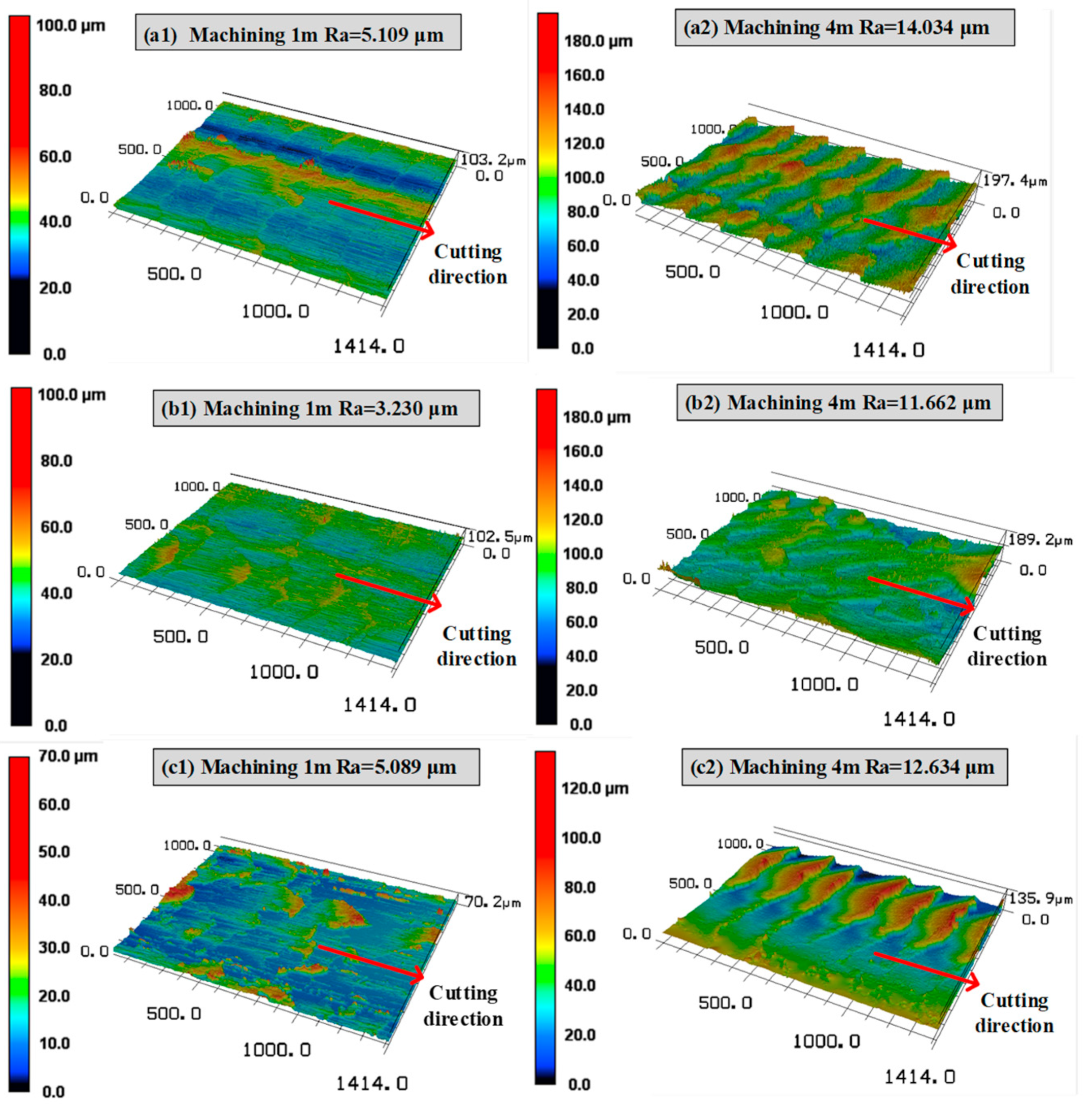
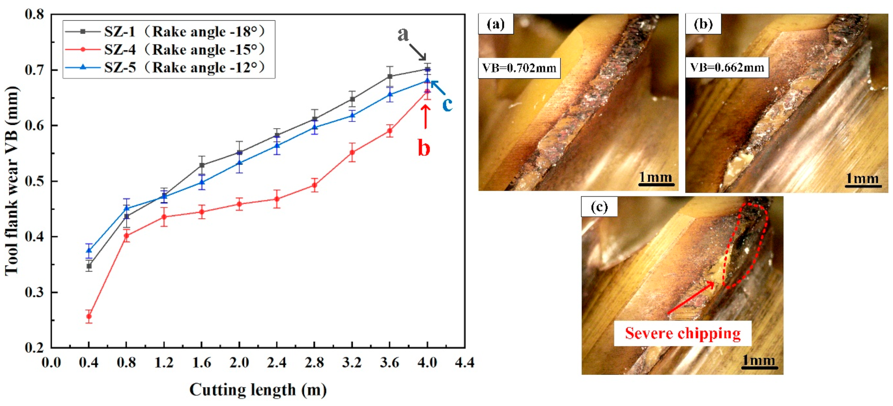
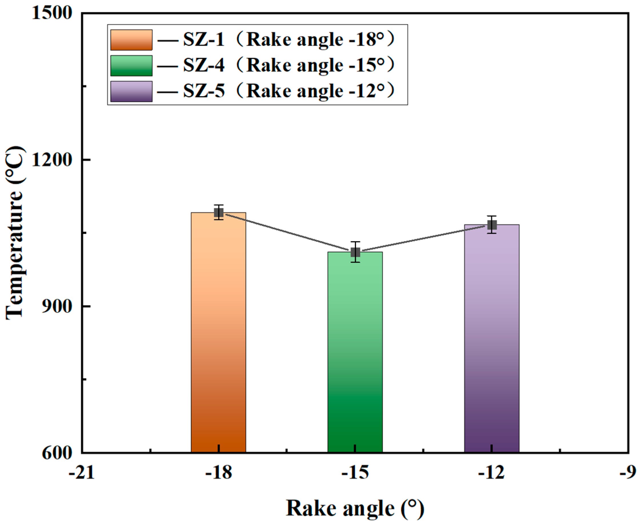
3.2. Effect of Rake Angle on the Cutting Performance of Sialon Ceramic End Mills

The curve of cutting force with cutting distance for Sialon ceramic end mills with different rake angles are shown in Figure 8. The cutting force rose smoothly with the increase in cutting distance when the rake angle of the ceramic end mill was slight, and a decreasing trend is seen in the cutting force with the growth of the rake angle. However, when the rake angle was increased to −12°, the cutting force had a sudden increase during the machining process caused by chipping. As shown in Figure 9, the cutting edge of ceramic end mill was severely chipped when the rake angle was −12°. The flank wear of the tool decreases first and then increases with the increase in the rake angle of the tool, indicating that the flank wear of the ceramic end mill is the smallest when the rake angle of the tool was −15°. The rake angle of the end mill is increased to improve the cutting edge’s sharpness and the chip’s deformation, which has a particular role in reducing the cutting force and tool wear. But it also seriously affects the strength of the cutting edge. When the rake angle becomes too large, the ceramic end mill is easy to break under a large load and impact due to the low strength of the cutting edge, resulting in a sudden increase in cutting force [36]. With the increases in the rake angle, the cutting temperature of the ceramic end mill decreased first and then increased in Figure 10. From the cutting force analysis, it could be observed that when the rake angle was increased to −15°, the cutting force and flank wear were decreased, which have reduced the output of cutting heat. The larger rake angle will reduce the heat dissipation area of the ceramic end mill, thereby reducing the heat dissipation performance of the tool, reducing the discharge of cutting heat, and resulting in an increase in cutting temperature [32,37]. Therefore, when the rake angle was −15°, the ceramic end mill had no chipping phenomenon and had a small cutting force and tool wear, which had a better cutting performance.
It can be observed in Figure 11that the roughness of workpiece surface decreased and then increased with the increase in the rake angle. When the rake angle is −15°, the surface roughness is 8.51 µm, which is 32.6% and 6.5% lower than that of the other two ceramic end mills, indicating that the surface quality of the workpiece has been improved by appropriately increasing the rake angle. However, surface roughness has a slight increase when the rake angle was increased from −15° to −12°, which was attributed to the chipping of the cutting edge when the rake angle of the ceramic end mill was −12°. The morphology of the machined surface of the three types of ceramic end mills was similar when the cutting distance was 1 m, as shown in Figure 12. In the late cutting stage, there were many scale spurs on the machined surface of the workpiece when the rake angle of the ceramic end mill was −18°, while for the rake angles of −15° and −12°, the machined surface were almost free of scale spurs, which were caused by lower tool wear and cutting temperature. There were more chips on the machined surface in Figure 12(c2) when the rake angle was −12°, which was caused by the lower strength of the cutting edge. Therefore, the surface quality of the workpieces machined with Sialon ceramic end mills were best when the rake angle was −15°.

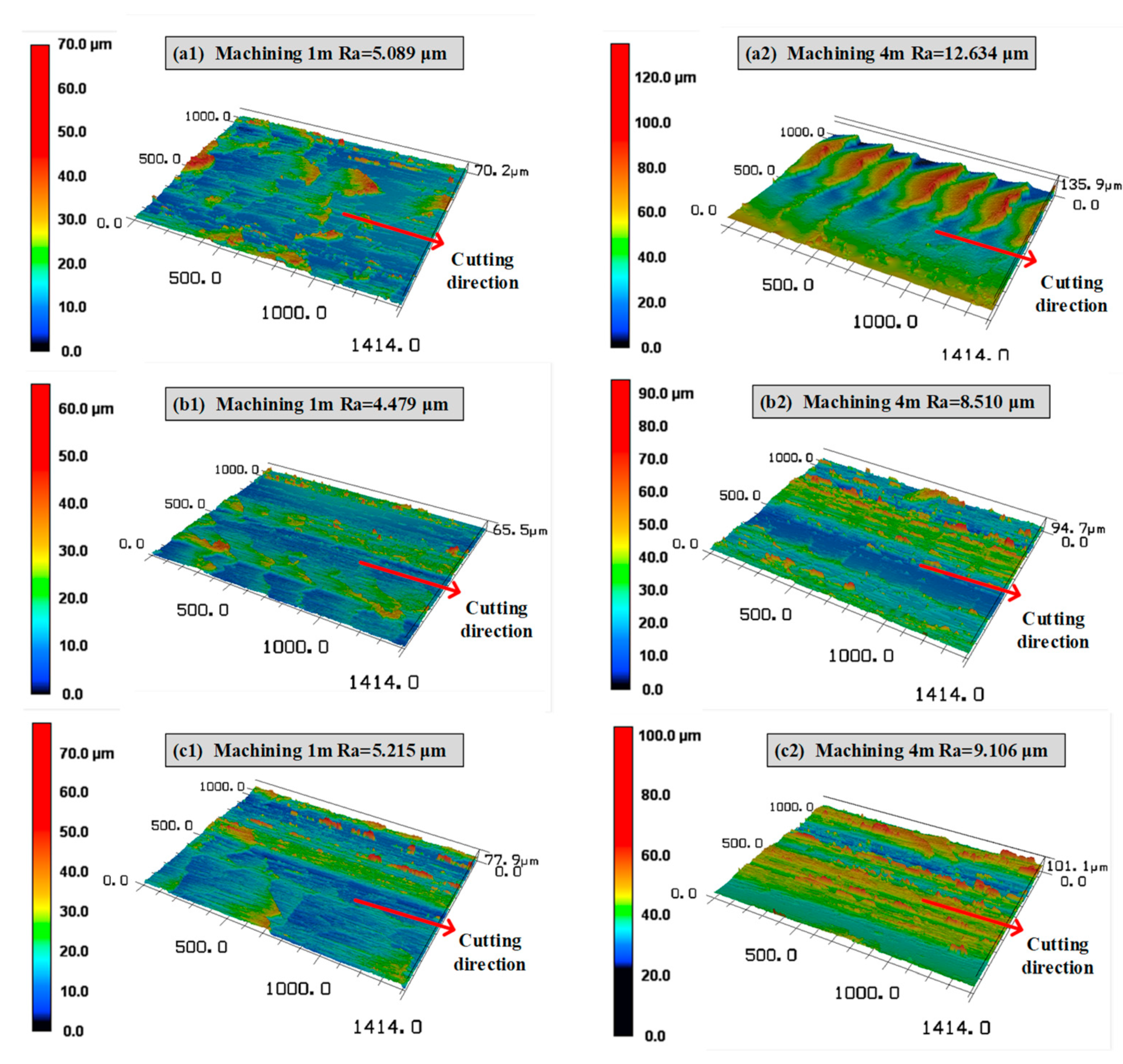
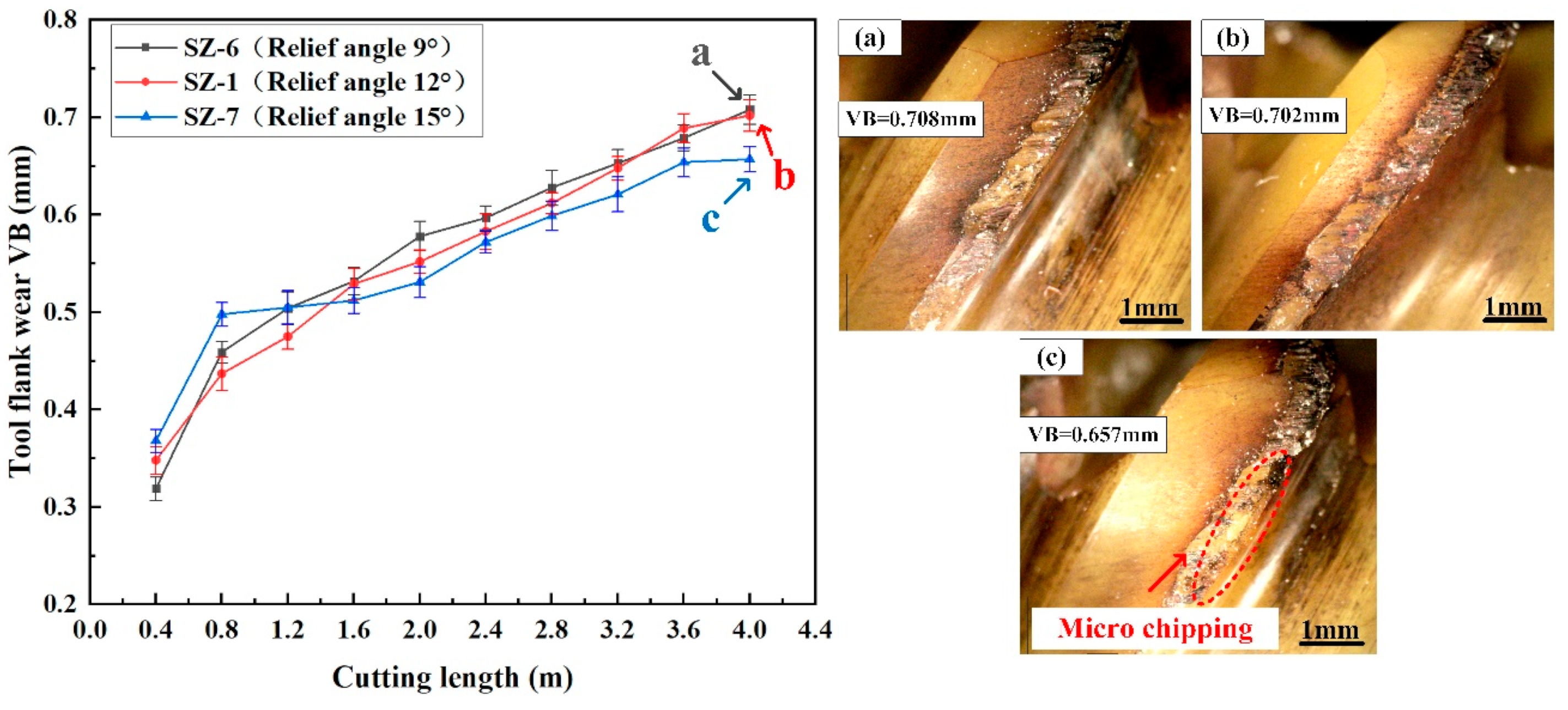
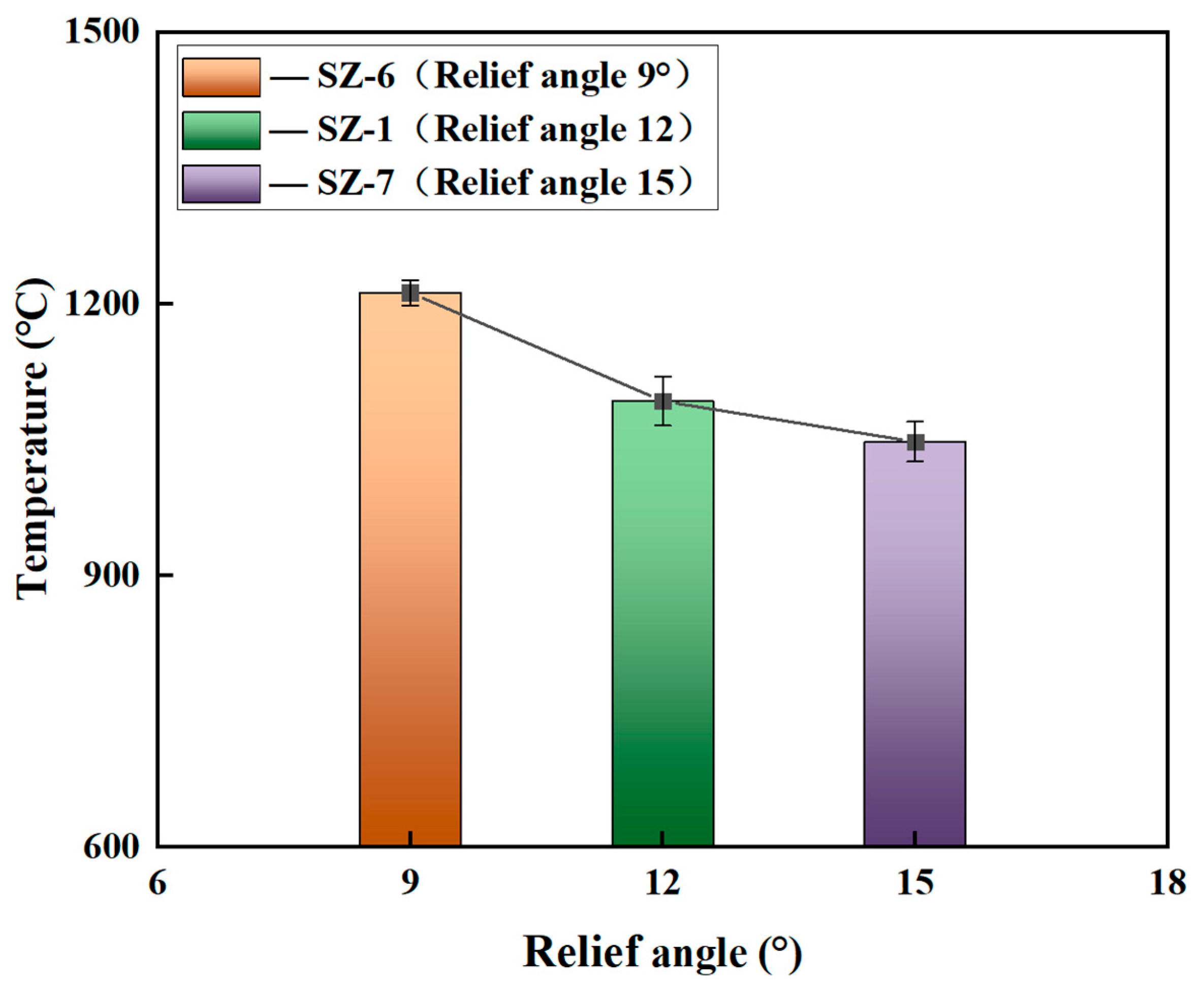
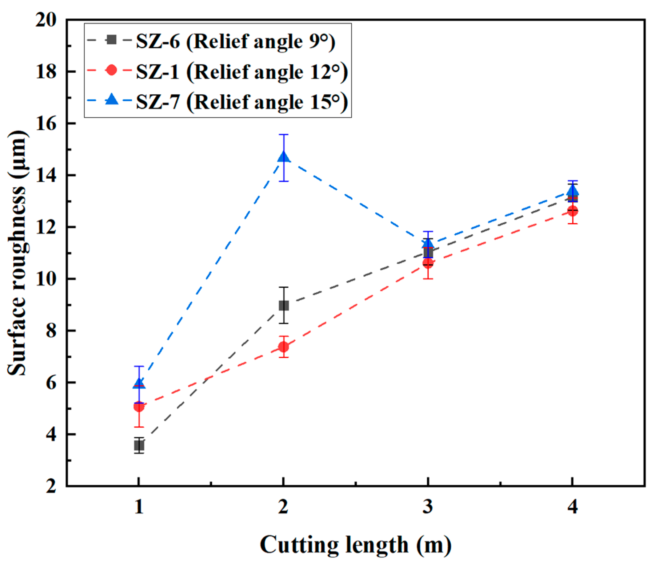
3.3. Effect of Relief Angle on the Cutting Performance of Sialon Ceramic End Mills

As shown in Figure 13, the cutting force decreased and then increased with the increase in the relief angle. The cutting force kept a relatively sizeable increasing trend in the first cutting stage when the relief angle of the ceramic milling cutter was 9°. When the relief angle was 9°, the contact area between the tool flank and the machined surface was increased, which caused a rapid increase in friction and cutting force. When the back angle of the ceramic end mill is 12°, the cutting force rises more smoothly, while when the back angle of the ceramic end mill is 15°, the cutting force increases rapidly in the early stage of cutting. Although a large relief angle benefited the reduction of friction and improved the sharpness of the cutting edge, it would seriously affect the strength of the tool, which would cause the chipping of the cutting edge when the cutting force was small and the cutting force to increase suddenly. The effect of the relief angle of the ceramic end mill on tool wear was not significant in Figure 14, which was closely related to the change in cutting temperature and tool breakage. In the first stage of cutting, when the back angle of the ceramic end mill is 9°, the flank wear value increases rapidly, resulting in a rapid increase in cutting force. After cutting a certain distance, the flank wear tends to be stable and the cutting force rises slowly. It can be observed that when the unloading angle is 15°, the cutting edge has a large gap, which is the main reason for the increase in cutting force in Figure 14c. The cutting temperature of the ceramic end mill gradually decreased with the increase in the relief angle in Figure 15. The reason was that the contact area between the flank surface and the machined surface was reduced with the increase in the relief angle, which reduced the friction between the tool and the workpiece, the frictional heat and the cutting temperature. When the relief angle increases from 9° to 15°, the cutting temperature decreases by 120 and 45 °C, respectively, indicating that an appropriate increase in the unloading angle can significantly reduce the cutting temperature. When the relief angle of the ceramic end mill is 9°, the cutting temperature is higher than the thermal softening temperature of the workpiece material, which can also reduce the cutting force and tool wear during the cutting process.
The effect of the relief angle of the ceramic end mill on the surface roughness is shown in Figure 16. In the later stage of cutting, the surface roughness of the workpiece was minimal when the relief angle of ceramic end mill was 12°. It can be observed that when the relief angle of the ceramic end mill was 15°, the surface roughness increased rapidly and then decreased, which is related to the chip of the cutting edge. A larger relief angle reduced strength of the cutting edge, and the tool suffered slight chipping under the large cutting force and impact load. Therefore, the workpiece material could not be completely removed, reducing the machined surface quality. However, the wear of the flank intensified and the tiny chipping at the cutting edge was blunted to form a new cutting edge with the cutting distance increased, which resulted in the surface roughness dropping to an average level. It can be observed that there is less debris on the machined surface due to the high strength of the cutting edge in the pre-cutting stage when the back angle of the ceramic milling cutter is 9° in Figure 17. However, a slight relief angle will increase the contact area between the flank and the machined surface, resulting in an increase in the extrusion and cutting temperature between the flank and the workpiece surface, which enhances the plastic flow of the workpiece surface material and forms a periodic peak valley perpendicular to the feed direction. The generation of periodic-scale spurs was found when the relief angle of the ceramic end mill was 15°, which was the main reason for its relatively large surface roughness, and further verified that chipping occurred on its cutting edge. During the late cutting stage, scale spurs were produced on the surface of the workpiece machined by all three types of ceramic milling cutters. When the relief angle is 9°, there are many chips on the surface of the workpiece, and the probability and number of scales are also high due to the strong extrusion effect caused by the wear of the flank. When the relief angle was 12°, the machined surface roughness was lower and had better surface quality.

4. Conclusions

This research evaluates the influence of the geometric structure of ceramic end mills on the cutting performance of ceramic end mills for machining nickel-based superalloy. When the helix angle, rake angle and relief angle of Sialon ceramic end mills were 35°, −15° and 12°, the best comprehensive cutting performance was achieved.
(1)
As the helix angle of the ceramic end mill increases, the cutting force and temperature gradually decrease. When the helix angle reaches 35°, the ceramic end mill exhibits the lowest wear and the best surface quality, along with low cutting force and temperature.
(2)
As the rake angle of the ceramic end mill increases, the flank wear and the quality of the machined surface of the workpiece initially decrease and then increase. When the rake angle of the ceramic end mill is −15°, it exhibits the lowest cutting force and temperature during cutting, along with good machined surface quality.
(3)
With the increase in the relief angle, the cutting temperature of the ceramic end mill gradually decreases, while the cutting force and the machined surface roughness show a trend of first decreasing and then increasing. When the relief angle of the ceramic end mill is 12°, it exhibits a lower cutting force and temperature, along with the best surface quality of the workpiece.

Author Contributions

K.X.: conceptualization, methodology, validation, formal analysis, investigation, writing—original draft. B.Z.: conceptualization, formal analysis, resources, writing—review and editing. P.C., W.L., L.L., W.C., X.W. and Z.X.: formal analysis. The author’s contribution corresponds their order. All authors have read and agreed to the published version of the manuscript.

Funding

This research was funded by the National Natural Science Foundation, grant number 52175336.

Institutional Review Board Statement

Not applicable.

Informed Consent Statement

Not applicable.

Data Availability Statement

All data generated or analyzed during this study are included in this published article.

Conflicts of Interest

The authors have no conflict of interest to declare that are relevant to the content of this article. All authors certify that they have no affiliations with or involvement in any organization or entity with any financial interest or non-financial interest in the subject matter or materials discussed in this manuscript.

References

  1. Guo, Y.B.; Li, W.; Jawahir, I.S. Surface integrity characterization and prediction in machining of hardened and difficult-to-machine alloys: A state-of-the-art research Review and analysis. Mach. Sci. Technol. 2009, 13, 437–470. [Google Scholar] [CrossRef]
  2. Choudhury, I.A.; EI-Baradie, M.A. Machinability of nickel-base super alloys: A general review. J. Mater. Process. Technol. 1998, 77, 278–284. [Google Scholar] [CrossRef]
  3. Arunachalam, R.; Mannan, M.A. Machinability of nickel-based high temperature alloys. Mach. Sci. Technol. 2000, 4, 127–168. [Google Scholar] [CrossRef]
  4. Thakur, D.G.; Ramamoorthy, B.; Vijayaraghavan, L. Study on the machinability characteristics of superalloy Inconel 718 during high speed turning. Mater. Des. 2009, 30, 1717–1725. [Google Scholar] [CrossRef]
  5. Wang, Z.; Liu, Y.; Zou, B.; Huang, C.Z.; Xue, K.; Shi, Z.Y. Mechanical properties and microstructure of Al2O3-SiCw ceramic tool material toughened by Si3N4 particles. Ceram. Int. 2019, 46, 8845–8852. [Google Scholar] [CrossRef]
  6. Cui, E.Z.; Zhao, J.; Wang, X.C.; Song, Q.H. Cutting performance, failure mechanisms and tribological properties of GNPs reinforced Al2O3/Ti(C,N) ceramic tool in high speed turning of Inconel 718. Ceram. Int. 2020, 46, 18859–18867. [Google Scholar] [CrossRef]
  7. Slavko, D.; Borivoj, S.; Janez, K. Wear mechanisms of cutting tools in high-speed cutting processes. Wear 2001, 250, 349–356. [Google Scholar]
  8. Li, H.Z.; Zeng, H.; Chen, X.Q. An experimental study of tool wear and cutting force variation in the end milling of Inconel 718 with coated carbide inserts. J. Mater. Process. Technol. 2006, 180, 296–304. [Google Scholar] [CrossRef]
  9. Bhatt, A.; Attia, H.; Vargas, R.; Thomson, V. Wear mechanisms of WC coated and uncoated tools in finish turning of Inconel 718. Tribol. Int. 2010, 43, 1113–1121. [Google Scholar] [CrossRef]
  10. Jindal, P.C.; Santhanam, A.T.; Schlenkofer, U.; Shuster, A.F. Performance of PVD TiN, TiCN, and TiAlN coated cemented carbide tools in turning. Int. J. Refract. Met. Hard Mater. 1999, 17, 163–170. [Google Scholar] [CrossRef]
  11. Devillez, A.; Schneider, F.; Dominiak, S.; Dudzinski, D.; Larrouquere, D. Cutting forces and wear in dry machining of Inconel 718 with coated carbide tools. Wear 2007, 262, 931–942. [Google Scholar] [CrossRef]
  12. Sun, H.W.; Zou, B.; Chen, W. Cutting performance of Silicon-based ceramic end milling tools in high-efficiency machining of GH4099 under dry condition. Int. J. Adv. Manuf. Technol. 2022, 118, 1719–1732. [Google Scholar] [CrossRef]
  13. Sugihara, T.; Enomoto, T. High Speed Machining of Inconel 718 Focusing on Tool Surface Topography of CBN Tool. Procedia Manuf. 2015, 1, 675–682. [Google Scholar] [CrossRef]
  14. Zheng, G.M.; Zhao, J.; Gao, Z.J.; Cao, Q.Y. Cutting performance and wear mechanisms of Sialon–Si3N4 graded nano-composite ceramic cutting tools. Int. J. Adv. Manuf. Technol. 2012, 58, 19–28. [Google Scholar] [CrossRef]
  15. Wang, Y.S.; Zou, B.; Wang, J.C.; Wu, Y.; Huang, C.Z. Effect of the progressive tool wear on surface topography and chip formation in micro-milling of Ti–6Al–4V using Ti (C7N3)-based cermet micro-mill. Tribol. Int. 2020, 141, 105900. [Google Scholar] [CrossRef]
  16. Mandal, H.; Kara, F.; Turan, S.; Kara, A. Novel SiAlON ceramics for cutting tool applications. Key Eng. Mater. 2003, 237, 193–202. [Google Scholar] [CrossRef]
  17. Bitterlich, B.; Bitsch, S.; Friederich, K. SiAlON based ceramic cutting tools. J. Eur. Ceram. Soc. 2008, 28, 989–994. [Google Scholar] [CrossRef]
  18. Kitagawa, T.; Kubo, A.; Maekawa, K. Temperature and wear of cutting tools in high-speed machining of Inconel 718 and Ti-6Al-6V-2Sn. Wear 1997, 202, 142–148. [Google Scholar] [CrossRef]
  19. Li, Y.S.; Zou, B.; Shi, Z.Y.; Huang, C.Z.; Li, L.; Liu, H.L.; Zhu, H.T.; Yao, P.; Liu, J.K. Wear patterns and mechanisms of sialon ceramic end-milling tool during high speed machining of nickel-based superalloy. Ceram. Int. 2021, 47, 5690–5698. [Google Scholar] [CrossRef]
  20. Zheng, G.M.; Zhao, J.; Li, A.H.; Cui, X.B.; Zhou, Y.H. Failure Mechanisms of Graded Ceramic Tool in Ultra High Speed Dry Milling of Inconel 718. Int. J. Precis. Eng. Manuf. 2013, 14, 943–949. [Google Scholar] [CrossRef]
  21. Molaiekiya, F.; Aramesh, M.; Veldhuis, S.C. Chip formation and tribological behavior in high-speed milling of IN718 with ceramic tools. Wear 2020, 446, 203191. [Google Scholar] [CrossRef]
  22. Sun, H.W.; Zou, B.; Chen, P.; Huang, C.Z.; Guo, G.Q.; Liu, J.K.; Li, L.; Shi, Z.Y. Effect of MQL condition on cutting performance of high-speed machining of GH4099 with ceramic end mills. Tribol. Int. 2022, 167, 107401. [Google Scholar] [CrossRef]
  23. Sun, J.F.; Huang, S.; Ding, H.T.; Chen, W.Y. Cutting performance and wear mechanism of Sialon ceramic tools in high speed face milling GH4099. Ceram. Int. 2020, 46, 1621–1630. [Google Scholar] [CrossRef]
  24. Ma, Z.; Xu, X.W.; Huang, X.H.; Ming, W.W.; An, Q.L.; Chen, M. Cutting performance and tool wear of SiAlON and TiC-whisker-reinforced Si3N4 ceramic tools in side milling Inconel 718. Ceram. Int. 2022, 48, 3096–3108. [Google Scholar] [CrossRef]
  25. Çelik, A.; Alağaç, M.S.; Turan, S.; Kara, A.; Kara, F. Wear behavior of solid SiAlON milling tools during high speed milling of Inconel 718. Wear 2017, 378–379, 58–67. [Google Scholar] [CrossRef]
  26. Tian, X.H.; Zhao, J.; Zhao, J.B.; Gong, Z.C.; Dong, Y. Effect of cutting speed on cutting forces and wear mechanisms in high-speed face milling of Inconel 718 with Sialon ceramic tools. Int. J. Adv. Manuf. Technol. 2013, 69, 2669–2678. [Google Scholar] [CrossRef]
  27. Ming, W.W.; Huang, X.H.; Ji, M.; Xu, J.Y.; Zou, F.; Chen, M. Analysis of cutting responses of Sialon ceramic tools in high-speed milling of FGH96 superalloys. Ceram. Int. 2021, 47, 149–156. [Google Scholar] [CrossRef]
  28. Grguras, D.; Kern, M.; Pusavec, F. Suitability of the full body ceramic end milling tools for high speed machining of nickel based alloy Inconel 718. Procedia CIRP 2018, 77, 630–633. [Google Scholar] [CrossRef]
  29. Zhang, H.J.; Sun, C.Y.; Liua, M.; Gao, F.S. Analysis of the optimization of tool geometric parameters for milling of Inconel 718. Mater. Sci. Eng. 2019, 423, 012030. [Google Scholar]
  30. Wu, H.B.; Xu, C.G.; Wang, X.C.; Zhang, Z. Influence of Tool Geometrical Parameters in High Speed Cutting of Aluminum Alloy. In Proceedings of the 2010 International Conference on Intelligent Computation Technology and Automation, Changsha, China, 11–12 May 2010; pp. 533–536. [Google Scholar]
  31. Qin, Z.; Wang, C.Y.; Lin, Y.S.; Hu, Y.N. Optimisation of tool angles and the relation between tool path and cutting force in high-speed milling with micro-end-mill. Int. J. Comput. Appl. Technol. 2007, 28, 20–26. [Google Scholar] [CrossRef]
  32. Nie, L.F.; Zhang, L.W.; Zhu, Z.; Xu, W. Constitutive Modeling of Dynamic Recrystallization Kinetics and Processing Maps of Solution and Aging FGH96 Superalloy. J. Mater. Eng. Perform. 2013, 22, 3728–3734. [Google Scholar] [CrossRef]
  33. Daniel, F.; Marcus, S.; Friedrich, B. End milling of Inconel 718 using solid Si3N4 ceramic cutting tools. Procedia CIRP 2019, 81, 1131–1135. [Google Scholar]
  34. Ondin, O.; Kivak, T.; Sarikaya, M.; Yildirim, C.V. Investigation of the influence of MWCNTs mixed nanofluid on the machinability characteristics of PH 13-8 Mo stainless steel. Tribol. Int. 2020, 148, 106323. [Google Scholar] [CrossRef]
  35. Huang, X.H.; Zou, F.; Ming, W.W.; Xu, J.Y.; Chen, Y.; Chen, M. Wear mechanisms and effects of monolithic Sialon ceramic tools in side milling of superalloy FGH96. Ceram. Int. 2020, 46, 26813–26822. [Google Scholar] [CrossRef]
  36. Liao, T.K.; Jiang, F.; Yan, L.; Cheng, X. Optimizing the geometric parameters of cutting edge for finishing machining of Fe-Cr-Ni stainless steel. Int. J. Adv. Manuf. Technol. 2017, 88, 2061–2073. [Google Scholar] [CrossRef]
  37. Sulaiman, S.; Ariffin, M.K.A.; Roshan, A. Finite Element Modeling of the Effect of Tool Rake Angle on Cutting Force and Tool Temperature during High Speed Machining of AISI 1045 Steel. Adv. Mater. Process. Technol. 2013, 939, 194–200. [Google Scholar]
Figure 1. The EDS elemental analysis of Sialon ceramic materials.
Coatings 13 01483 g001
Figure 2. (a) The installation of high-speed milling of GH4099 superalloy, (b) schematic diagram of the setup of temperature measurement and (c) schematic illustration of the side milling.
Coatings 13 01483 g002
Figure 3. The cutting force variation of ceramic end mills with different helix angles.
Coatings 13 01483 g003
Figure 4. The flank wear variation of ceramic end mills with different helix angles and wear states of each mill: (a) SZ-2 ceramic end mill, (b) SZ-3 ceramic end mill and (c) SZ-1 ceramic end mill.
Coatings 13 01483 g004
Figure 5. Effect of helix angle of ceramic end mills on cutting temperature.
Coatings 13 01483 g005
Figure 6. Effect of the helix angle of ceramic end mills on the roughness of machined surfaces.
Coatings 13 01483 g006
Figure 7. Three-dimensional morphology of the machined surface at different stages of each mill: (a1,a2) ceramic end mill with 30° helix angle, (b1,b2) ceramic end mill with 35° helix angle and (c1,c2) ceramic end mill with 40° helix angle.
Coatings 13 01483 g007
Figure 8. The cutting force variation of ceramic end mills with different rake angles.
Coatings 13 01483 g008
Figure 9. The flank wear variation of ceramic end mills with different rake angles and wear states of each mill: (a) SZ-1 ceramic end mill, (b) SZ-4 ceramic end mill and (c) SZ-5 ceramic end mill.
Coatings 13 01483 g009
Figure 10. Effect of rake angle of ceramic end mills on cutting temperature.
Coatings 13 01483 g010
Figure 11. Effect of the rake angle of ceramic end mills on the roughness of machined surfaces.
Coatings 13 01483 g011
Figure 12. Three-dimensional morphology of the machined surface at different stages of each mill: (a1,a2) ceramic end mill with −18° rake angle, (b1,b2) ceramic end mill with −15° rake angle and (c1,c2) ceramic end mill with −12° rake angle.
Coatings 13 01483 g012
Figure 13. The cutting force variation of ceramic end mills with different relief angles.
Coatings 13 01483 g013
Figure 14. The flank wear variation of ceramic end mills with different relief angles and wear states of each mill: (a) SZ-6 ceramic end mill, (b) SZ-1 ceramic end mill and (c) SZ-7 ceramic end mill.
Coatings 13 01483 g014
Figure 15. Effect of relief angle of ceramic end mills on cutting temperature.
Coatings 13 01483 g015
Figure 16. Effect of the relief angle of ceramic end mills on the roughness of machined surfaces.
Coatings 13 01483 g016
Figure 17. 3D morphology of the machined surface at different stages of each mill: (a1,a2) ceramic end mill with 9° relief angle, (b1,b2) ceramic end mill with 12° relief angle and (c1,c2) ceramic end mill with 15° relief angle.
Coatings 13 01483 g017
Table 1. The element composition of GH4099 (wt.%).
NiCrCoWMoAlTiFe
Bal18.926.375.834.021.981.21≤2
CMgSiCeMnSPB
≤0.08≤0.01≤0.50≤0.02≤0.40≤0.015≤0.015≤0.005
Table 2. The physical properties of GH4099.
Density
(g·cm−3)
Young’s Modulus (GPa)Tensile Strength (MPa)Elongation
(%)
Hardness
(HV)
Thermal
Conductivity
(W·(m·K)−1)
8.47210≤1130≥30≤30010.47
Table 3. The mechanical properties of Sialon ceramic end mill.
Density (g/cm3)Hardness (GPa)Flexural Strength (MPa)Fracture Toughness (MPa⋅m1/2)
3.3219.6742.97.7
Table 4. The angle optimization scheme.
NumberDiameter (mm)Core Diameter (mm)Flute and Full Length (mm)Helix Angle
(°)
Rake Angle
(°)
First Relief Angle
(°)
Second Relief Angle (°)
SZ-1121010 + 7040−181222
SZ-2121010 + 7030−181222
SZ-3121010 + 7035−181222
SZ-4121010 + 7040−151222
SZ-5121010 + 7040−121222
SZ-6121010 + 7040−18919
SZ-7121010 + 7040−181525
Table 5. The machining parameters.
Cutting Speed/m·min−1Feed Rate/mm·z−1Axial Cutting Depth/mmRadial Cutting Depth/mm
4000.0440.8
Disclaimer/Publisher’s Note: The statements, opinions and data contained in all publications are solely those of the individual author(s) and contributor(s) and not of MDPI and/or the editor(s). MDPI and/or the editor(s) disclaim responsibility for any injury to people or property resulting from any ideas, methods, instructions or products referred to in the content.

