1. Introduction
Gene sequencing, an innovative biotechnology to determine the sequence of nucleic acids or amino acids, plays an important role in life sciences research and modern biology [
1]. Benefitting from the rapid development of biotechnology, gene sequencing technology has evolved from the first generation of “Sanger sequencing” [
2] to the second generation of “high-throughput sequencing” [
3], and then to the third generation of “single molecule sequencing” [
4]. High-throughput detection technology enables people to obtain a large amount of genomic information more accurately in a shorter period of time [
5]. Essentially, gene sequencing is performed to analyze the arrangement of four bases: Adenine (A), Thymine (T), Cytosine (C) and Guanine (G). There are four methods that can achieve recognition of bases, the bioluminescence method [
6], fluorescence detection method [
7], solution pH value method [
8], and current measurement method [
9], among which the fluorescence detection method is currently the most widely used because of its advantages of stability, reliability, and strong anti-interference ability.
In general, fluorescence technology for gene sequencing needs to follow the following principles: First, the four bases on the DNA are carried with different fluorophores, which can emit different wavelengths of fluorescence when stimulated. Then, by recognizing these fluorescence wavelengths, the type of base marked by fluorophores can be identified, so that the base sequence can be recorded correspondingly. In the past, sequencing strategies were mainly composed of single-color imaging, dual-color asynchronous imaging, and four-color imaging [
10]. In recent years, with the continuous deepening of precise medical concepts, especially the increasing demand for disease control and prevention, medical instruments have gradually developed towards miniaturization and rapid detection [
11], and the dual-color synchronous imaging gene sequencing technology has emerged. Only two fluorophores and two detectors were utilized, but this advanced technology can recognize four bases simultaneously [
12]. Compared with other methods, dual-color synchronous imaging shows shorter data processing time than four-color imaging and higher detection efficiency than dual-color asynchronous imaging, which can effectively simplify optical systems of sequencers, and reduce fluorophore consumption and sequencing cost [
13] in line with the development trend of equipment miniaturization. This technology has been widely used in medium- or high-throughput desktop gene sequencing instruments in clinical medical testing.
As the key optical component in gene sequencing instruments, filters can be used in fluorescence detection systems to select light within a specific wavelength range, remove interference signals, or change the direction of light, etc. The performance filters directly determine the sensitivity and accuracy of gene sequencing instruments [
14]. With the continuous improvement in the sensitivity and accuracy requirements for gene sequencers, the technical requirements for filters (such as passband transmittance, cutoff steepness, etc.) are also increasing.
2. Spectral Parameter Design for Filter Group
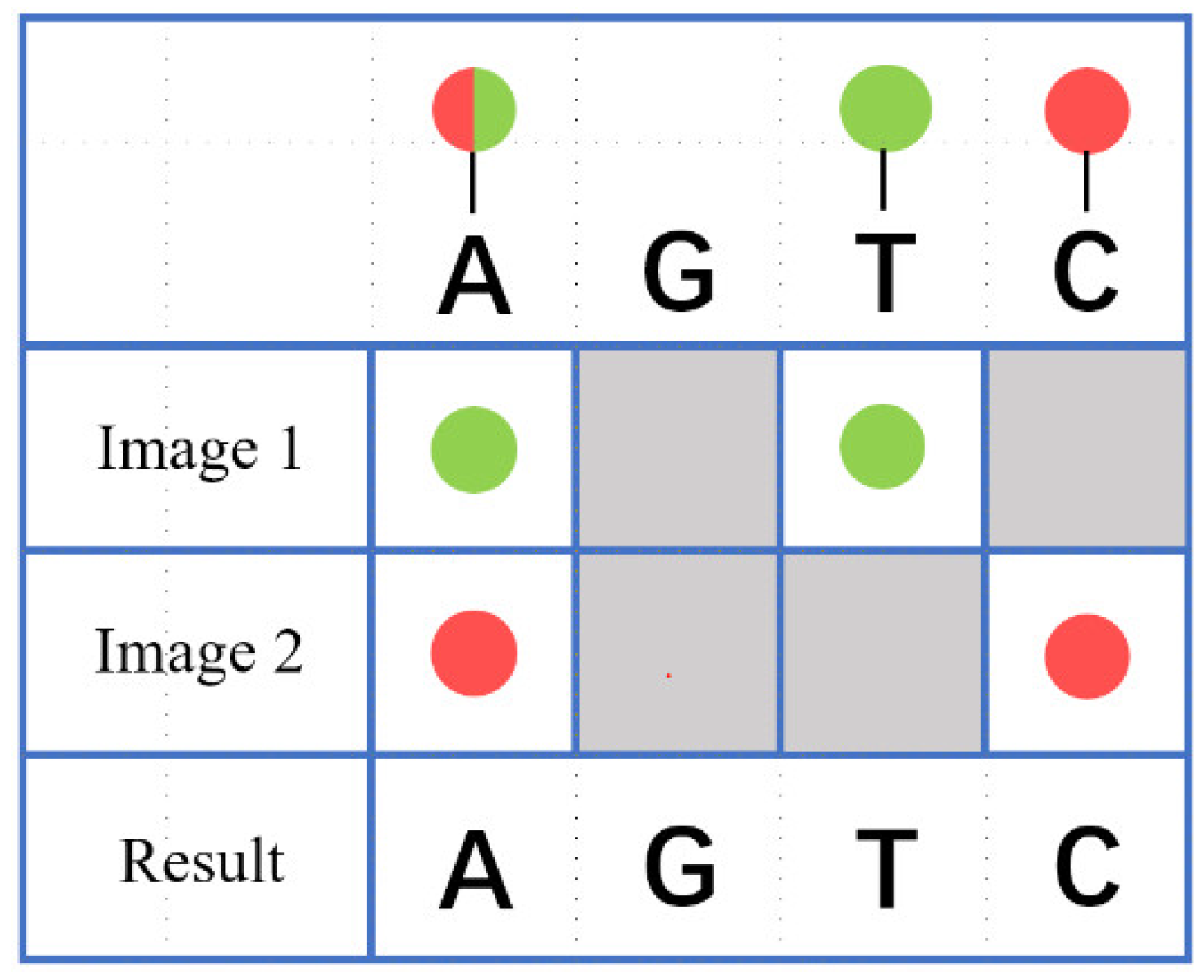
In dual-color synchronous imaging technology, four bases on biological samples are labeled with two fluorophores: Thymine (T) is marked with a green fluorescent group, Cytosine (C) is marked with a red fluorescent group, Adenine (A) is marked with a green and red fluorescent group, and Guanine (G) is not marked. After being excited by two beams of excitation light, Adenine (A) emits both green and red fluorescence, Guanine (G) does not emit fluorescence, Thymine (T) emits only green fluorescence, and Cytosine (C) emits only red fluorescence. The type of base can be distinguished based on the color of these fluorescences, as shown in
Figure 1.
Based on the principle of fluorescence detection, the spectral separation and filtering optical path structure for dual-color synchronous imaging was designed as illustrated in
Figure 2. Two lasers emitted two different wavelengths of excitation lights simultaneously, used to excite fluorophores. An excitation filter was used to purify excitation light. By using a dichroic mirrors group, two types of excitation light can be illuminated onto biological samples, while the fluorescence emitted can be guided into two sets of detectors. Each specific emission filter was placed correspondingly in front of each detector so that stray lights can be eliminated. In addition, there was also a focusing optical path in this structure to achieve the fast-focusing imaging of the system. Optical components typically undergo stress deformation after coating, which has little effect on transmitted wavefront distortion but can worsen reflected wavefront distortion. In this optical system, in order to achieve clearer imaging effects, the emitted fluorescence was designed to pass through optical components in a transmitted manner as much as possible, which reduced the reflected wavefront distortion and improved the imaging quality.
Due to the fact that the excitation and emission light of the two fluorophores share the same optical path, there must be a certain gap between the absorption peak of the long-wave fluorophore and the emission peak of the short-wave fluorophore to avoid them interfering with each other. Based on this principle, fluorophore FAM (green fluorescence) and TAMRA (red fluorescence) were selected as markers. Their fluorescence absorption and emission spectra are shown in
Figure 3 [
15], with excitation peaks at 490 nm and 553 nm, respectively. An Ar ion laser with a wavelength of 488 nm and He-Ne laser with a wavelength of 543 nm were selected as excitation light sources. CCD receivers were selected as fluorescence detectors, and 850 nm light was used for automatic focusing.
High transmission, sharp cut-off steepness, and deep blocking are necessary characteristics of high-performance fluorescence detection filters to meet the demanding needs of gene sequencers. In this instrument, two excitation light sources shared the same excitation filter, so the dual bandpass was designed as an excitation filter. Lasers, which have good monochromaticity, were used as excitation lights. Therefore, the bandwidth of the excitation filter should be as narrow as possible to achieve a higher degree of isolation from fluorescence, while the bandwidth should also be sufficient to accommodate the wavelength deviation of the lasers. The emission filter should have as wide a bandwidth as possible to obtain a stronger fluorescence signal when ensuring isolation from the two excitation sources. The schematic passband positions of these filters relative to the fluorophore spectra are shown in
Figure 4. Depending on the spectral response range of CCD, the blocking range of the excitation filter and the emission filters were OD > 6@200–1100 nm (outside the passband). The excitation lights were lasers, so if we wanted to achieve a satisfactory signal-to-noise ratio, the blocking of the emission filters at the positions of excitation light should be higher than OD8, and the blocking at the intersection point between them should be higher than OD5.
Dichroic mirrors should minimize the loss of light energy while taking on the role of light-splitting in the optical path. The laser dichroic mirror in the optical path has double-notch spectral characteristics. The detailed spectral index parameters of the designed filter group are shown in
Table 1.
3. Optical Coating Design for Filter Group
In this gene sequencing filters set, the FAM emission filter, TAMRA emission filter, focusing dichroic mirror, and fluorescence dichroic mirror were conventional filters that were relatively easy to design and manufacture, so they did not need to be emphasized. The spectra of the excitation filter and laser dichroic mirror were relatively complex, so they were used as examples in coating system design, manufacturing, and testing in this work.
The FAM emission filter and TAMRA emission filter were single-bandpass filters. When designing these filters, multiple Fabry–Perot cavity structures can be used as the initial coating system, however, a long-pass structure combined with a short-pass structure can also be used as the initial coating system. The blocking of the rejection bands was achieved by the stacking of several long-pass structures or short-pass structures. The method of double-sided coating on a single glass substrate can be adopted, so the coating thickness on each side can be reduced and the manufacturing difficulty can be decreased.
Both the focusing dichroic mirror and the fluorescence dichroic mirror need a single spectral edge, and their transmission band and reflection band were separated by a considerable distance, which means that a sharp cutoff is not necessary. The spectral requirements can be met, even without handling the polarization separation for P and S at the incidence angle of 45°. In other words, a normal long-pass structure (0.5 H L 0.5 H)
n can be used as the initial coating system. For some dichroic mirrors with high cut-off steepness requirements, three materials can be used for their initial design, and the intermediate refractive index material then replaced with a three-layer symmetric (pqp) structure; the two-material-coating system that was easier to manufacture can then be obtained [
16].
The excitation filter was a dual-bandpass filter. There are various reports on the design of this type of filter [
17,
18]. In this paper, the multi-band filter design method based on the cyclic-nested model was adopted [
19]. The initial coating system was [(HL)
m αH (LH)
m βL]
n where H represented Nb
2O
5, L represented SiO
2., α was the interval layer coefficient, β was the matching layer coefficient, and where these together determined the number of passbands and their relative positions. m was the number of cycles for the reflection stack, which determined the half-width of the passband. n was the total number of cycles, which determined the whole blocking. According to the spectral requirements, these coefficients in the coating system were adjusted as follows: α = 4, β = 0.41, m = 3, n = 10. The conjugate gradient method was used to achieve optimization, and the extremely thin layers were removed properly. Finally, the main coating, which contained 138 layers with a thickness of 10.5 μm, was obtained. The main coating cannot achieve the blocking for all required bands, and therefore, an auxiliary coating was designed by stacking long-pass structures or short-pass structures to achieve the whole blocking requirement on the other side of the substrate. The designed auxiliary coating contained 178 layers, and its thickness was 10.5 μm. After stacking corresponding coating systems on both sides, the final designed spectral for the excitation filter is presented in
Figure 5.
The laser dichroic mirror was a double-notch filter at the incidence angle of 45°. When designing this dichroic mirror, we adopted our self-developed initial coating system of a multi-notch dichroic mirror, which has the characteristics of high cut-off steepness, depolarization, adjustable numbers, and adjustable position of the notch. This initial coating system was (0.5LcHbL2aHbLcH0.5L)
n where H represented Nb
2O
5, L represented SiO
2, a was the notch coefficient, and where it can be used to adjust the number of notches. b and c were the depolarization coefficients, which can be used to adjust the degree of depolarization. n was the total number of cycles, which determined the cut-off steepness and the reflection. According to the spectral requirements, these coefficients in the coating system were adjusted as follows: a = 1.416, b = 0.151, c = 0.416, n = 14. The conjugate gradient method was used to achieve optimization, and the extremely thin layers were removed properly. Finally, the main coating, which contained 77 layers with a thickness of 13.8 μm, was obtained. In order to improve the transmittance, the AR coating should be coated on the other side of the substrate. After stacking corresponding coating systems on both sides, the final designed spectral for the laser dichroic mirror is shown in
Figure 6.
4. Deposition Process for Optical Coatings
The commonly used multi-layer hard oxide optical-coating technologies include electron gun with ion assisted deposition (IAD), ion beam sputtering deposition (IBS), and plasma assisted reactive magnetron sputtering deposition (PARMS). IAD has a relatively low deposition stability, which limits its application in ultra-multi-layer (>100 layers) coatings. IBS shows high deposition stability and fewer coating defects, but due to its slow deposition rate and small uniform area, its manufacturing cost is relatively high. PARMS has high sputtering energy and relative high deposition stability, its deposition rate is equivalent to IAD, and its coating surface quality is similar to IBS; this means its comprehensive performance is excellent, and it is suitable for manufacturing ultra-multi-layer high-precision optical coatings.
Among this group of filters, the focusing dichroic mirror and the fluorescence dichroic mirror had fewer film layers, thinner total thickness, and larger film tolerances. This means they can be deposited by IAD. The excitation filter, the laser dichroic mirror, and the two emission filters, whose thicknesses exceed 10 μm on each one side, were manufactured by PARMS (BUHLER Leybold, Alzenau, Germany) with the Helios device, which is made by BUHLER Leybold, Alzenau, Germany. PARMS is a sputtering coating technology that combines an intermediate-frequency twin-target reactive magnetron sputtering with an ECWR radio-frequency plasma source. This device was equipped with an OMS (optical monitoring system) optical coating thickness control system, which can achieve precise film-thickness control and a stable deposition process. By adding oxygen, the Nb and Si targets underwent oxidation reactions during the coating process. In terms of the sputtering control of Nb
2O
5, to ensure that every deposited film layer can be fully oxidized, an oxygen partial pressure controller (λ-Sensor) was used to control sputtering power; in terms of sputtering control of SiO
2, the method of constant sputtering power was adopted, which not only ensured the stability of the sputtering state, but also facilitated adjusting the deposition rate to achieve higher film-thickness control accuracy. The detailed process parameters are shown in
Table 2.
Because of extreme optimization, the main coating for the excitation filter and laser dichroic mirror showed great variety in the thickness of each layer, and the coating system was very sensitive to thickness deviations. The simulation results with thickness deviations of 0.3% and 0.15% (by Essential Macleod) (Thin Film Center, Tucson, AZ, USA) (version 10.4.523) are shown in
Figure 7 and
Figure 8.
For such high-sensitive coating systems, it was necessary to use a direct film-thickness control method with multiple monitoring films to reduce thickness deviations. In addition, for these thin layers below 15 nm, the time-monitoring method is more useful. After completing the design of the entire film-thickness monitoring scheme, OMS simulator software was used, so that the monitoring errors and the possible results could be evaluated. If the evaluation results were not satisfactory, the monitoring scheme could be adjusted again until the evaluation met our expectations.
6. Conclusions
Based on the principles of gene sequencing application and fluorescence detection, a dual-color synchronous gene sequencing splitting optical path structure was designed. By combining this optical system and the selected fluorophores’ absorption and emission spectra, the filter group parameters were designed. Taking the excitation filter and the laser dichroic mirror as examples, a dual bandpass-filter and dual-notch dichroic mirror were designed. The filters were manufactured by IAD and magnetron sputtering methods. The manufactured filters met the design requirements, and the satisfying application effect was presented when they were applied in customer-desktop medium-throughput gene sequencers. With the development of gene sequencing technology, it will be required to further improve the cut-off steepness of filters in the future. This involves designing new coating systems for filters with extremely high transmittance and sharp cut-off steepness, researching stable and accurate deposition processes for more layers of optical coatings, and researching precise testing methods for sharper cut-off steepness, in order to meet the further development needs of the industry.


