Article

Effects of Fibre-Reinforced Plastic Wedge-Stick Slope on the Performance of Wind-Turbine Blade Root Connections

1
School of Materials Science and Engineering, Tongji University, Shanghai 201804, China
2
Aeolon Technology Co., Ltd., Shanghai 201306, China
*
Author to whom correspondence should be addressed.
Coatings 2024, 14(1), 129; https://doi.org/10.3390/coatings14010129
Submission received: 26 December 2023 / Revised: 15 January 2024 / Accepted: 17 January 2024 / Published: 18 January 2024
(This article belongs to the Section Environmental Aspects in Colloid and Interface Science)

Abstract

:
Bushing-insert connections have emerged as efficient blade root connection designs. Bushing-insert connections with fibre-reinforced plastic (FRP) wedge-sticks enhance the strength and stability of the blade root, prevent stress concentration at the blade root, and improve the service life and reliability of the blade. However, studies on the failure mechanisms of the FRP wedge-sticks in bushing-insert connections are scarce. Hence, in this study, the influence of the FRP wedge-stick on the structural performance of the blade root was analysed by changing the slope of the FRP wedge-stick’s inclined surface at a constant thickness. The finite element method, sample testing, and full-size blade testing method were employed, and structural verification was conducted using an 84.5 m blade. The results reveal that the contact area of the inclined surface can be increased by reducing the slope of the FRP wedge-stick. This increase in area reduces the stress transmitted to each node of the FRP wedge-stick and blade root, prevents delamination of the FRP wedge-stick and blade root, and enhances the reliability of the blade root connection.

1. Introduction

Globally, countries are adopting low-carbon emission strategies to combat climate change and promote significant modifications to energy systems [1]. In addition to promoting energy conservation and efficiency, countries are actively developing new renewable energy sources to reduce their dependence on fossil fuels. Wind power generation has become a pivotal component in the effort to reshape the global energy structure [2,3]. As the largest energy consumer in the world, China plans to increase its share of renewable energy to 20% of its total energy consumption by 2030. China is estimated to increase its wind power generation capacity to 400 GW by 2030 [4]. However, to meet the surging demands, larger wind turbines are necessary to increase the efficiency and stability of power generation. However, there are major safety concerns associated with increasing the blade-rotor diameter. Therefore, researchers have begun to focus on the causes of wind turbine failure [5,6,7], actively monitoring the structural health and identifying the damage caused to wind turbines [8,9,10].
Most wind turbine failures can be attributed to blade failures [11]. Blade failures can be caused by various factors, including delamination damage [12], buckling damage, cracking damage [13], and damage due to environmental ageing [14,15]. Lee et al. [16] reported a blade fault that caused the blade to detach from the wind turbine at the Eclipse and Ocotillo wind farms. This failure was attributed to delamination damage at the root of the blade. Additionally, they observed the same failure mechanism while testing and simulating a 30 m long blade. A significant difference was found between the load distribution at the root of the slender and large wind turbine blade and the bending load distribution of the hollow cylinder in the root model. The authors observed that the delamination failure occurred at the root of the blade due to a local load increase, which separated the T-bolt connection. The blade root connection is a vital part of the connection between the blade and spindle, and its stability and reliability directly affect the safe operation of the entire wind power system. Currently, the most common types of blade root connections used in wind turbines are the T-bolt and bushing-insert connections.
The T-bolt connection is realised by drilling radial holes in the blade root and installing cylindrical nuts. This connection mode is widely used owing to its high production efficiency and quality control. Zheng and Chen [17] proposed a time-domain fatigue assessment method for floating offshore wind turbines (FOWTs) based on T-bolt connections. The method was employed to predict the effects of various design and installation factors on the fatigue life of blade root bolts. In addition, Zheng et al. [18] proposed a framework for evaluating the structural strength of thin-walled blade root joints of FOWTs and discussed the effects of joint form, T-bolt spacing, load conditions, and bolt pretension on the structural strength of FOWT blade root joints. Further, Verma et al. [19] studied a T-bolt-connected blade root using a three-dimensional finite element model. They examined an axial hub connection, considered the influence of the actual fitting process, and analysed the effect of the impact load on the connection.
Recently, bushing-insert connections have become popular in commercial designs. The load on a blade root increases as the blade length increases. The thickness of the blade root must be increased when employing a T-bolt, thus, excessively increasing the weight of the blade root and resulting in material overuse. The pre-installation of bushings inside a blade root can effectively enhance the strength and stability of the blade root and improve the service life and reliability of the blade. Ha [20] used two- and three-dimensional finite element analysis methods to study the stress concentration factor at the screw thread of a blade bolt on a large offshore platform. Ha comprehensively investigated the stress concentration factors on bolt connections and discovered that the primary approach to reducing the stress concentration factor was to reduce the bolt diameter. Hosseini-Toudeshky et al. [21] studied the progressive de-bonding of the root bonding joints of 660 kW wind turbine blades under static and cyclic loads. They used cylindrical and bonding zone models for metals, composite materials, and bonding components. When the load on the blade was more than 10 times the normal fatigue load, the adhesive at the root joint of the blade accrued significant damage after 1 month (one million fatigue load cycles).
The blade structure with bushing-insert connections, is incorporated with a fibre-reinforced plastic (FRP) wedge-stick and polyvinyl chloride (PVC)/polyethylene glycol terephthalate (PET). The FRP wedge-sticks, such as bolts and bushings, also play an important role in ensuring the integrity of blade root connections. Figure 1 depicts a model of the FRP wedge-stick. The FRP wedge-sticks can enhance the connection strength and rigidity of a blade root connection and have excellent tensile properties. They have small volumes and weights, which are essential factors for wind-blade design. Lightweight FRP wedge-sticks can reduce the overall weight of the blades, thereby improving the efficiency of wind–energy conversion. In addition, they have good corrosion resistance and are well-suited for wind power generation under harsh environmental conditions. Camargo et al. [22] used structural joints composed of FRP dowels in laminated wood beams as an alternative to connect pieces of wood; it proved the feasibility of using this material in dowel joints for wooden structures. Khelifa et al. [23] proposed a technique for modelling steel connections strengthened with FRP and the behaviour of the connection was simulated both under monotonic and cyclic loadings. Faudree et al. [24] reviewed the latest reinforcement methods to strengthen Ti/carbon-fibre-reinforced polymer hybrid joints. The FRP materials have great potential as a part of connectors. However, failure mechanisms of the FRP wedge-sticks in bushing-insert connections have not been investigated.
Hence, in this study, we investigated the performance of the FRP wedge-stick in a blade root with a bushing-insert connection and the influence of the slope of the FRP wedge-stick on the structural performance of the blade root. We used an 84.5 m blade for design verification in the finite element method, sample experiments, and a full-size blade test method.

2. Materials and Methods

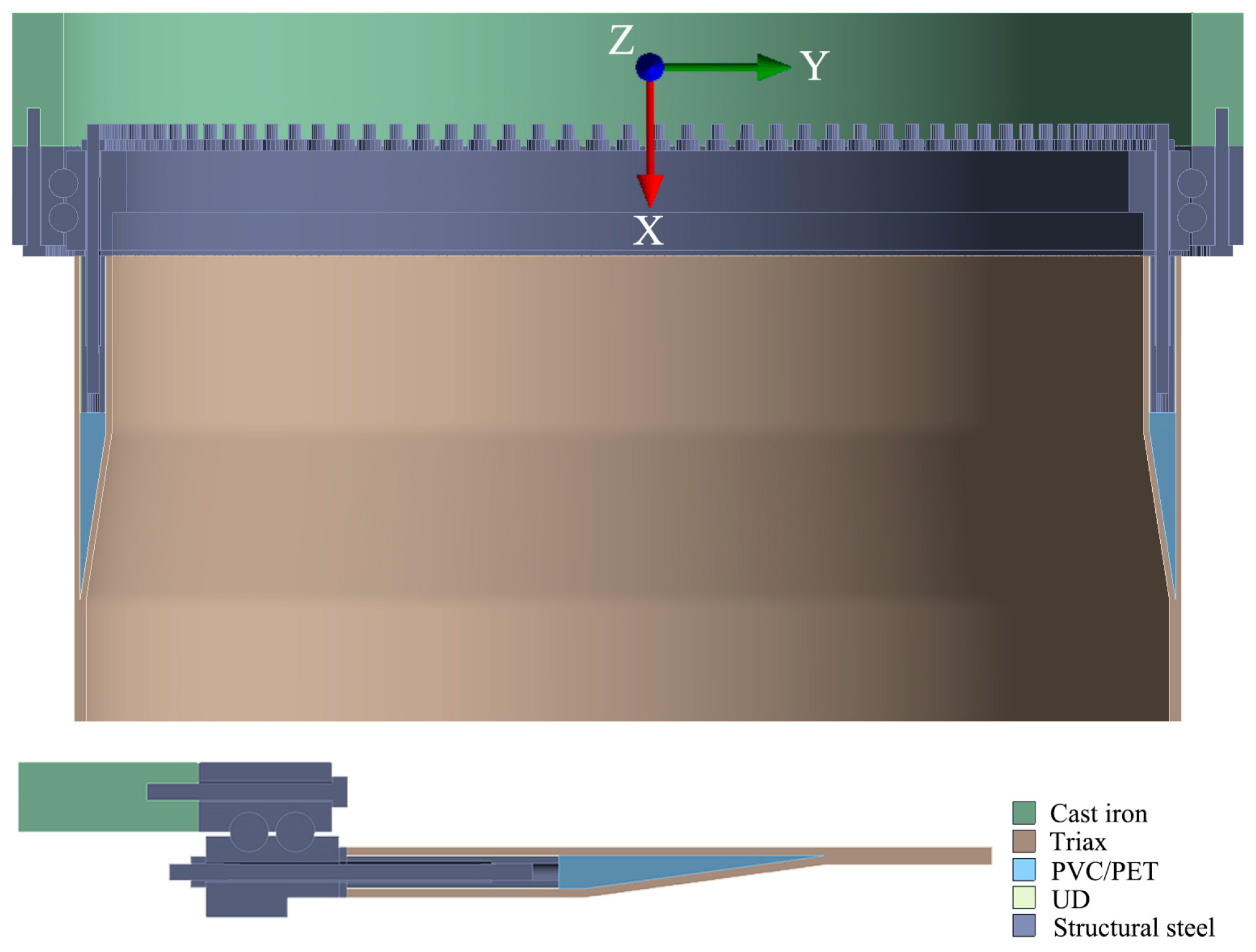
2.1. Establishment of a Finite Element Model

FRP wedge-sticks with inclined surface slopes of 1:7.3, 1:10, and 1:12 (full thickness: X axial length of the inclined surface) were designed, and a finite element model for the blade root of an 84.5 m long blade was developed. Table 1 lists some parameters of the 84.5 m blade.
Model development and mesh division are integral aspects of finite element modelling. The size of the model and the number of meshes directly affect the calculation scale and accuracy. In order to ensure a quick and convenient follow-up finite element analysis, only a part of the blade root was modelled. Due to symmetry, for the case of 112 bolts, the calculations used 1/224 of the entire model. This means on one edge, the bolt was sliced in order to have a half bolt in the model. On the other side, the model was sliced just in between two bolts. Figure 2 shows a schematic of the ½ and 1/224 finite element models used to establish the bushing-insert connection. Based on the parameters in Table 1, the solid model of each component of the blade root was established by the CATIA software (CATIA V5; the CATIA is a CAD/CAE/CAM-integrated software of the French company Dassault System, which supports all industrial design processes from pre-project stage, specific design, analysis, simulation and assembly to maintenance.). A mesh size of approximately 4 mm was defined and all the solid meshes were assigned SOLID185 unit properties. The solid elements were solved using the Static Structural analysis module in the finite element software ANSYS workbench (ANSYS 2021 R2; the ANSYS finite element software is a versatile finite element method computer design program that can be used to solve problems such as structures, fluids, electricity, electromagnetic fields, and collisions). Three different 1/224 finite element models were constructed with 155,456; 165,048; and 172,142 numbers of nodes and 122,593; 129,779; and 135,113 numbers of meshes. The coordinate system is also depicted in Figure 2.
The materials used in the connection components and material properties are listed in Table 2 and Table 3, respectively. Two boundary conditions were used to analyse the blade root: fixed support at the bottom surface of the hub and frictionless support at the 0° and 360/224° symmetry planes. The loads were defined in load steps. The bolt pretension was defined in the first loading step. As shown in Table 1, the bolt pretension was set to 187.5 kN (375 kN complete bolt) in the Static Structural analysis. The next loading step was for the external force, gradually loading to the limit force of 153 kN (306 kN complete bolt) of the half bolt. Several contact pairs were defined between the model parts that were touching each other. One type of contact pair was frictional contact, which was applied to surfaces in contact with the bearings and flanges. The coefficient of frictional contact was 0.2. The other type of contact pair was the bonding contact, which was applied between other contact surfaces, such as bolts and nuts, bolts and bushings, and bolts and hub.

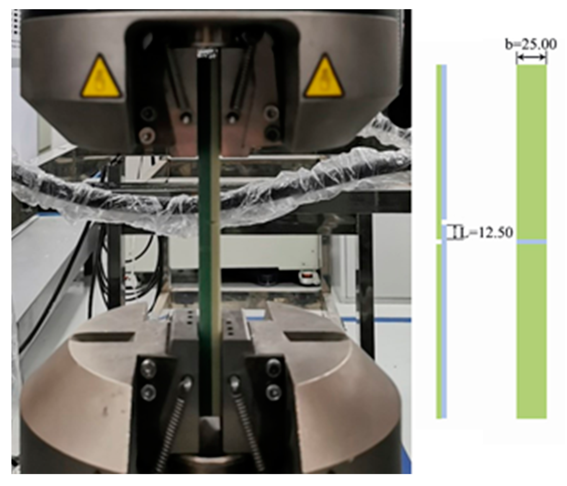
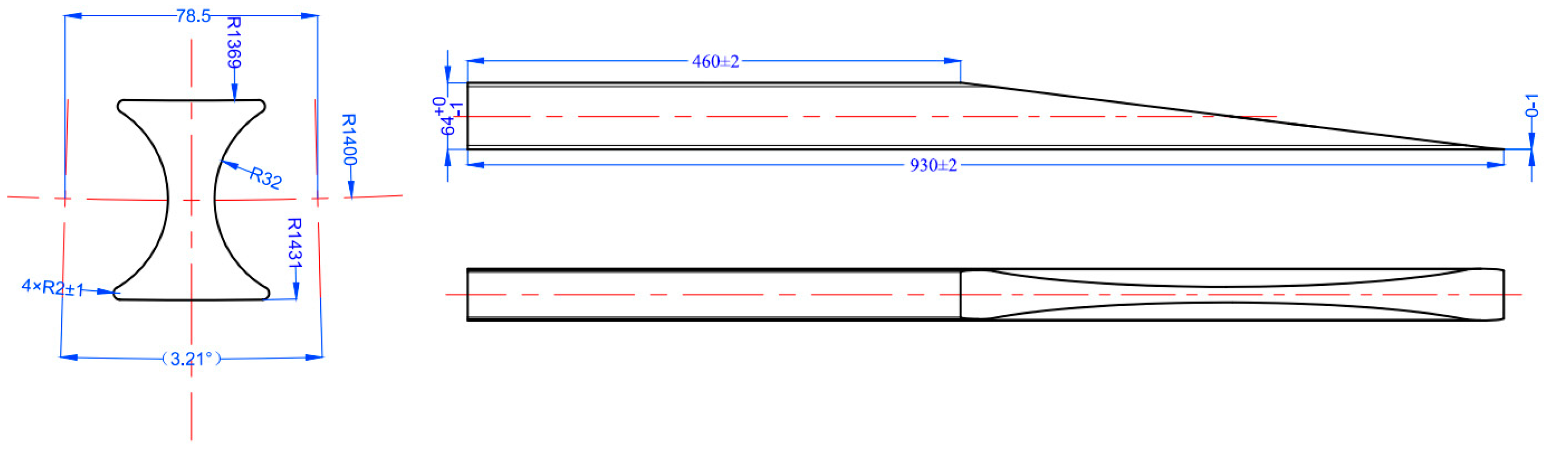
2.2. Sample Test and Full-Size Blade Test

To assess the maximum shear stress at the interface between the FRP wedge-stick and blade root, a single-lap shear test was performed for the glass fibre pultruded profile according to EN 1465-2009 test standards [25]. The number of test samples was 10. The preparation process of the test samples was as follows: 6 layers of E6-TLX1215 triaxial fabric (purchased from Zhenshi Holding Group Co., Ltd., Tongxiang, China) were laid on the glass fibre pultruded profile (purchased from Anhui Composite Technology Co., Ltd., Tongcheng, China) with a length of 300 mm and demoulding cloth removed. The fibre direction of the glass fibre pultruded profile should be consistent with the main fibre direction of the fabric. The preparation process adopted the vacuum infusion process, and the infusion resin system adopted WD 0135/0137 (purchased from Shanghai Kangda New Chemical Materials Group Co., Ltd., Shanghai, China). The infusion direction of the infusion resin system was perpendicular to the fibre direction of the glass fibre pultruded profile. The corresponding curing treatment was carried out according to the resin system. The temperature was raised at a rate of 0.5 °C/min to 50 °C and maintained at a constant temperature for 2 h. Then, the temperature was raised at a rate of 0.5 °C/min to 75 °C and maintained at a constant temperature for 5 h. Finally, the temperature was naturally lowered to below 40 °C for demolding treatment.
The test was conducted using an INSTRON 5982 test machine and a strain gauge displacement sensor purchased from Instron (Shanghai) Testing Equipment Trading Co., Ltd. (Shanghai, China) Test Equipment Trading Co., Ltd. The grip pressure and test speed were set to 20 bar and 1 mm/min, respectively. Figure 3 shows the test machine and sample sizes.
During the preparation process of full-size test blades, the FRP wedge-sticks were purchased from Anhui Composite Technology Co., Ltd. and made from E-glass fibre and epoxy resin using a pultrusion process. The dimensions of the FRP wedge-sticks with inclined surface slopes of 1:7.3 are shown in Figure 4. The unmarked linear and angular dimensional tolerances refer to level m in ISO 2768-1 [26], while the shape and position tolerances refer to level H in ISO 2768-2 [27]. The glue content of the FRP wedge-sticks is not less than 20%. According to the requirements of GB/T 8923.1-2011 [28], the surface of the FRP wedge-sticks shall be sandblasted and meet the requirements of Sa2.5. The surface roughness of the FRP wedge-stick sandblasting treatment is Ra ≥ 6.3 (Ra is arithmetic mean roughness).
Before installation, the FRP wedge-sticks were checked that there were no cracks, no dry spots, no stains, no foreign matter inclusions, no obvious fibre bending, no damage caused by external force impact, and no omission in rough treatment. The laying details of the FRP wedge-sticks, bushings, PVC and Triax fibre on the mould are shown in Figure 5a. The applied full-size testing procedure of the blade complied with the international standard IEC-61400-23 [29]. The bearing capacity and interface of the blade test bed, loading equipment, and test instruments and equipment were tested in the Aeolon Blade Test Center and met the test requirements (Figure 5b).

3. Results

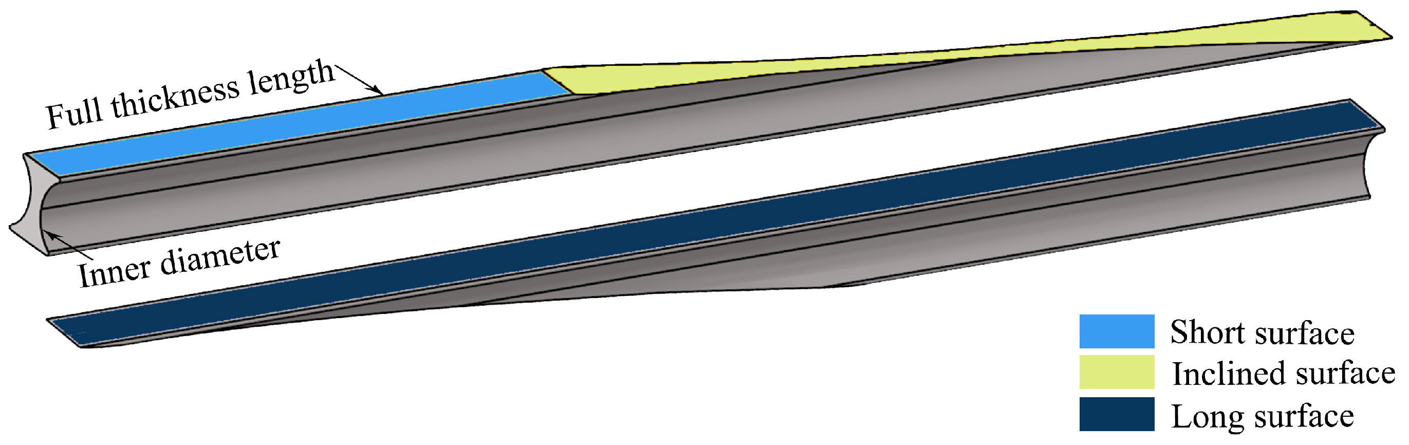
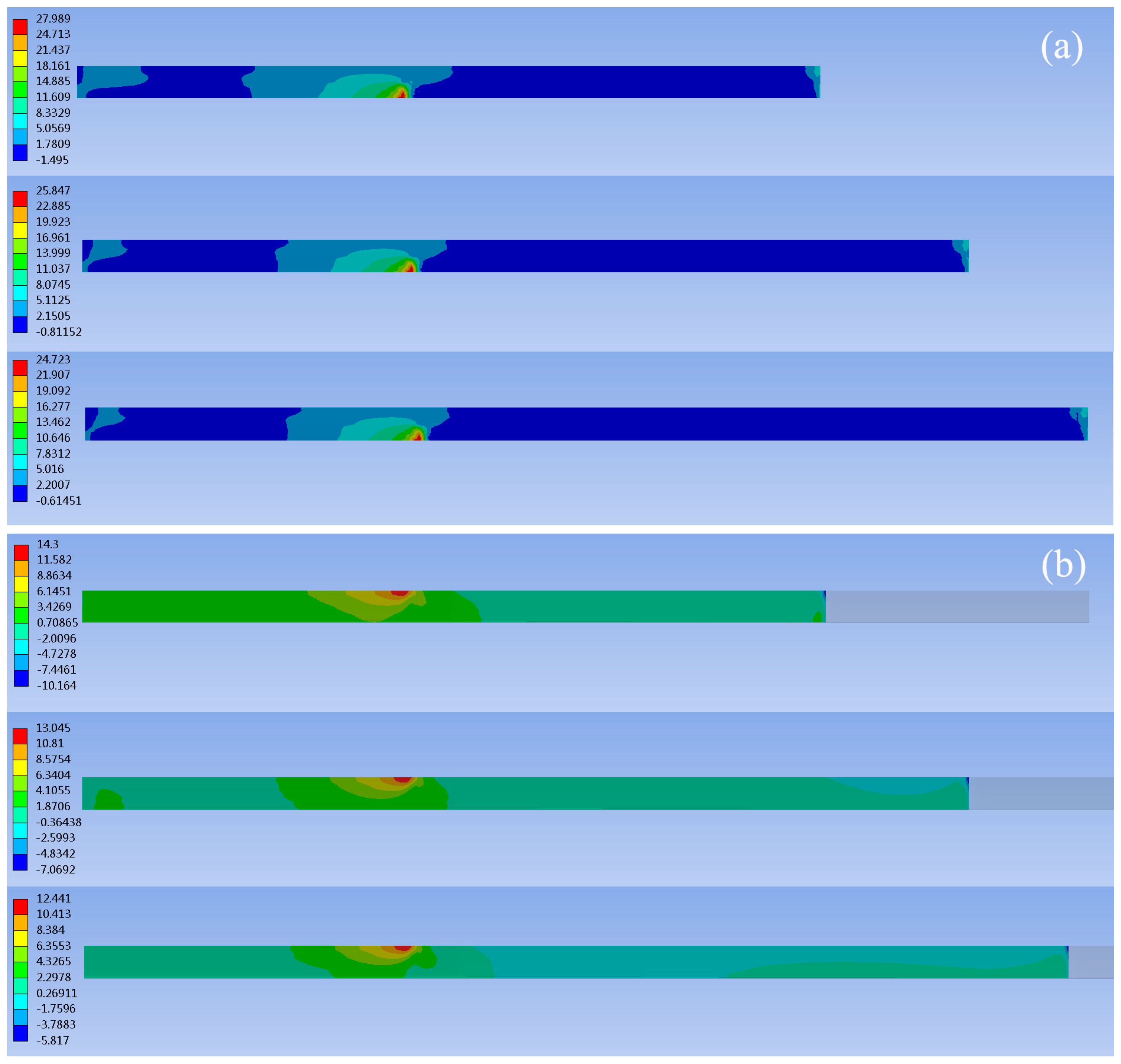
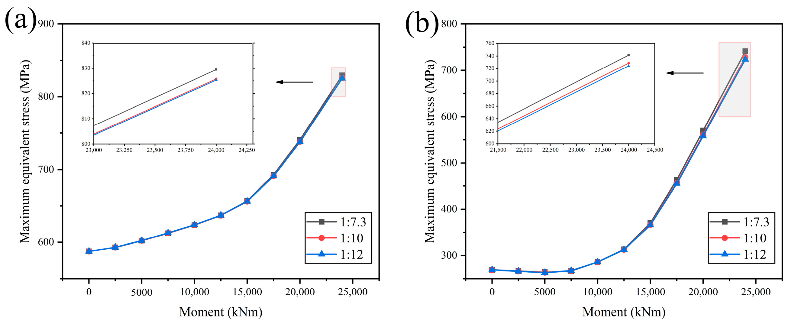
3.1. Finite Element Analysis of the FRP Wedge-Stick

A commonly observed failure mode of a blade root is the separation of the FRP wedge-sticks from the blade root. The finite element method was used to analyse the influence of the slope of the inclined surface of the FRP wedge-sticks on the contact surfaces between the FRP wedge-sticks and the blade root. The stress exerted on the contact surfaces between the FRP wedge-sticks and blade roots was examined during the operation. Subsequently, the critical stress was determined for reinforcing and enhancing the reliability of the blade root connection. The FRP wedge-stick and blade root share three contact surfaces (long, short, and inclined). The shear-stress cloud diagrams for the long and short contact surfaces are shown in Figure 6 and Figure 7, respectively. On the long surface, the shear stress decreased as the slope decreased, with the maximum stress appearing at the end of the bushing. Additionally, the shear stress increased as the thickness of the FRP wedge-stick decreased.
Corresponding to the slopes of 1:7.3, 1:10, and 1:12, the maximum shear stresses on the long surface of the FRP wedge-stick were 27.989, 25.847, and 24.723 MPa, respectively, and those on the long surface of the blade root were 14.300, 13.045, and 12.441 MPa, respectively. The maximum shear stress on the short surface of the FRP wedge-stick was experienced at the end position of the bushing. However, the maximum shear stress exhibited an increasing trend as the slope of the inclined surface increased (10.617, 12.321, and 13.306 MPa). As the slope increased, the position of the maximum shear stress on the short surface of the blade root moved forward to approximately 20 mm from the blade root end, and the maximum shear stress was maintained at approximately 9.3 MPa. The shear stress on the inclined surfaces of the FRP wedge-stick and blade root decreased as the inclined-surface slope decreased, and the maximum stress was experienced at the end of the FRP wedge-stick. The maximum shear stresses on the FRP wedge-stick inclined surface corresponding to the slopes of 1:7.3, 1:10, and 1:12 were 23.079, 15.289, and 13.781 MPa, respectively, and the maximum shear stresses on the inclined surface of the blade root were 17.513, 12.850, and 10.588 MPa, respectively.
The maximum normal stresses on the various FRP wedge-sticks and blade roots in the X, Y, and Z directions and the maximum shear stresses in the XY, XZ, and YZ planes were compared and analysed, as shown in Figure 8.
The results indicate that decreasing the slope of the inclined surface increased the contact area of the inclined surface, reducing the stress transmitted to each node of the FRP wedge-stick and blade root. Additionally, decreasing the slope improved the stress concentration between the FRP wedge-stick and blade root and improved the reliability of the blade root connection.
The maximum equivalent stresses were extracted and compared for the bolt and bushing whose dimensions remained unchanged, as shown in Figure 9.
The results indicate that extending the inclined surface contributes to reducing the maximum equivalent stress on the bolt and bushing. However, the contribution is insignificant, and the effect further decreases with the extension of the inclined surface.

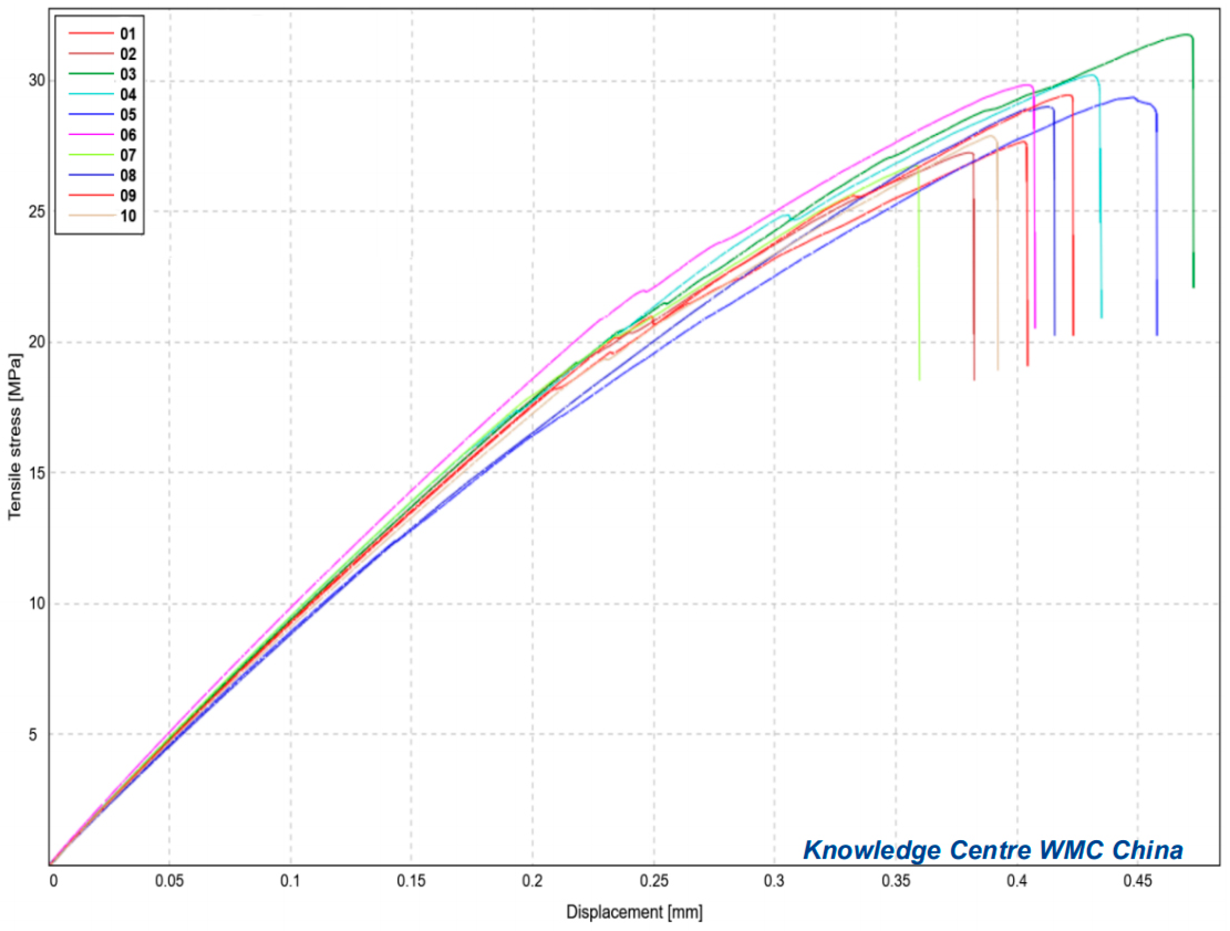
3.2. Testing of Sample Parts

Table 4 and Figure 10 present the test results for the 10 samples. The maximum, minimum, and average stresses were 31.76, 26.74, and 28.92 MPa, respectively.
According to the finite element analysis results in the Section 3.1, the maximum shear stress of the FRP wedge-stick with a transition slope of 1:7.3 was 27.989 MPa. The maximum shear stress was located on the long surface of the FRP wedge-stick. Although the maximum shear stress value was lower than the average test value of 28.92 MPa, it was higher than the minimum test value of 26.74 MPa. The theoretical value (27.989 MPa) of the failure of the connection between the FRP wedge-stick with a transition slope of 1:7.3 and blade root was very close to the results of the actual sample tests. This blade root connection structure was located at the end of the bushing and the FRP wedge-sticks. Excessive shear stress at the blade root may cause delamination, gradually deteriorating the overall structural stability of the blade root. The different test results of the samples indicated the complexity of the FRP wedge-sticks and blade root connections in actual production. In addition, it was necessary to consider the possible defects that may occur during the production and manufacturing process, which can also affect the safety of the blade root connection. The reliability of the overall structure of the blade root can be improved by increasing the transition ratio of the inclined surface to 1:10 and reducing the maximum shear stress to 25.847 MPa. This method can mitigate the risk of delaminating the FRP wedge-sticks and blade root.

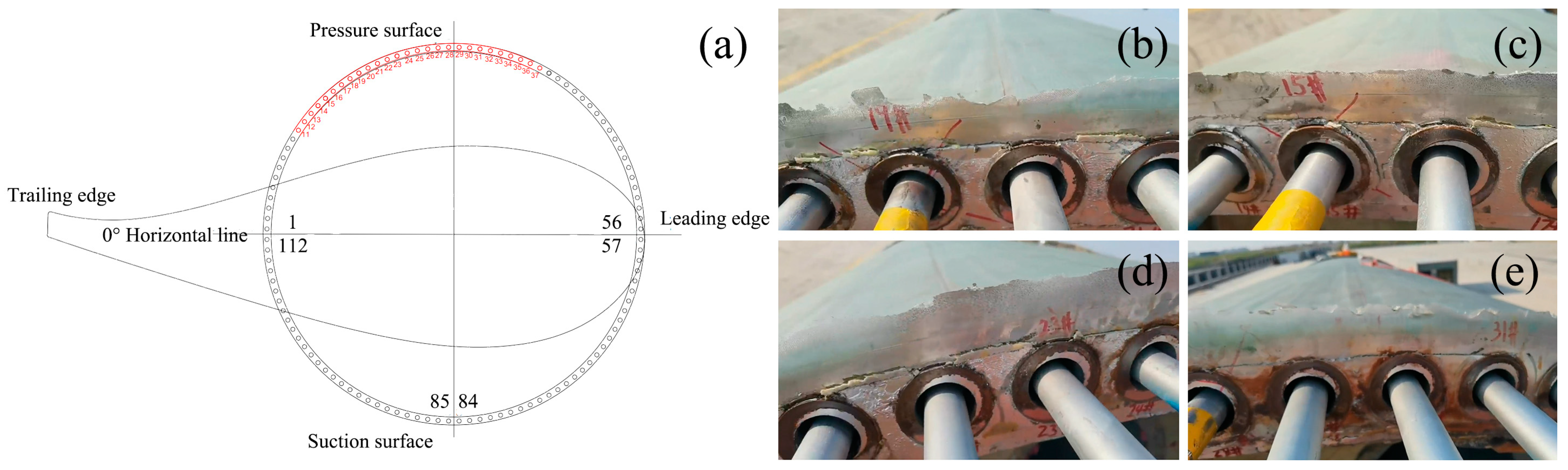
3.3. Testing of Blade Root

A full-scale test of the 84.5 m blade was conducted. During the test, the FRP wedge-sticks and bushings above the blade pressure surface were delaminated and separated by the blade root. Figure 11 shows the damage locations and photographs of the blade root. The preliminary assessment indicated that during the test, delamination occurred between the FRP wedge-sticks and blade root owing to an excessive shear stress between them.
This result is consistent with the finite element simulation and sample test results. The blade root of the 84.5 m blade was polished to investigate the cause of the damage further. After grinding, no abnormal phenomena were observed on the long surface of the blade root, as shown in Figure 12.
After additional grinding, interface separation occurred between the long surface of the FRP wedge-sticks and the blade root, as shown in Figure 12. The structure of the bushing insert connected to the blade root was optimised, the inclined surface of the FRP wedge-sticks was changed from 1:7.3 to 1:10, and the full-size model of the blade was further tested.
Applying a static load to a blade in the flapwise and edgewise directions is a rapid and accurate method of determining the ultimate bearing capacity and overall stiffness of the blade. The target load was statically applied to the 84.5 m blade in the flapwise and edgewise directions. No limit failure such as bolt breakage, fibre failure, or bonding failure occurred at the blade root, thereby meeting the standard (IEC-61400-23 [29]) requirements. Fatigue loads applied to the blade in the flapwise and edgewise directions can be used to verify the fatigue load capacity of the blade root during the intended operating life. Fatigue loads were applied to the 84.5 m long blade 1 and 2.5 million times in the flapwise and edgewise directions, respectively. This test verified that the blade root would remain structurally sound without fatigue damage during its 20-year operating period. Therefore, the blade root of the 84.5 m blade successfully passed the fatigue test conducted in the flapwise and edgewise directions.

4. Conclusions

In this study, the performance of an FRP wedge-stick inserted in a bushing-insert connection was investigated via finite element analysis, sample testing, and full-size blade testing. In practical applications, well-suited and optimised bushing-insert structures and materials can be selected depending on the specific requirements of wind turbines. This will help achieve a long-term and stable operation of wind turbine blades. The most significant points of this conclusion can be summarised as follows:
  • Decreasing the inclined-surface slope of the FRP wedge-stick could effectively improve the strength and stability of the blade root and improve the service life and reliability of the blade;
  • The maximum shear stress of the FRP wedge-stick is located on the long surface, at the end position on the tip side of the bushing;
  • Extending the inclined surface has a small contribution to reducing the maximum equivalent stress on the bolt and bushing;
  • The effects of other sizes of the FRP wedge-stick, such as the inner diameter and full thickness length, and changes in the overall structure of the bushing insert cannot be ignored. Currently, the single-inclined transition mode is the most commonly used for FRP wedge-sticks. In the near future, a multi-inclined transition mode and even improved designs for FRP wedge-sticks could be developed.

Author Contributions

Conceptualization, Y.S.; methodology, Y.S.; software, Y.Q.; validation, C.H., P.Q. and H.L.; formal analysis, Y.S.; investigation, Y.S.; resources, J.L.; data curation, Y.Q.; writing—original draft preparation, Y.S.; writing—review and editing, Y.Q., C.H., P.Q., H.L. and J.L.; visualization, Y.Q.; supervision, C.H., P.Q., H.L. and J.L.; project administration, C.H.; funding acquisition, Y.S. All authors have read and agreed to the published version of the manuscript.

Funding

This research received no external funding.

Data Availability Statement

The data presented in this study are available on request from the corresponding author.

Acknowledgments

The authors would like to thank Weiguang Xing, Yangyang Chen, and Zhenhui Weng of Aeolon Technology for their technical support.

Conflicts of Interest

Authors Yihang Qu, Congli Hu, Peiyu Qi and Huawei Liu were employed by the company Aeolon Technology Co., Ltd., Shanghai, China. The remaining authors declare that the research was conducted in the absence of any commercial or financial relationships that could be construed as a potential conflict of interest.

References

  1. Msigwa, G.; Ighalo, J.O.; Yap, P.S. Considerations on environmental, economic, and energy impacts of wind energy generation: Projections towards sustainability initiatives. Sci. Total Environ. 2022, 849, 157755. [Google Scholar] [CrossRef] [PubMed]
  2. Amano, R.S. Review of wind turbine research in 21st century. J. Energy Resour. Technol. 2017, 139, 050801. [Google Scholar] [CrossRef]
  3. Kaewniam, P.; Cao, M.; Alkayem, N.F.; Li, D.; Manoach, E. Recent advances in damage detection of wind turbine blades: A state-of-the-art review. Renew. Sustain. Energy Rev. 2022, 167, 112723. [Google Scholar] [CrossRef]
  4. He, J.-K. China’s INDC and non-fossil energy development. Adv. Clim. Change Res. 2015, 6, 210–215. [Google Scholar] [CrossRef]
  5. Kling, A.; Sørensen, J.D. Scale-up of wind turbine blades—Changes in failure type. In Proceedings of the European Wind Energy Conference and Exhibition 2012, Copenhagen, Denmark, 16–19 April 2012. [Google Scholar]
  6. Mishnaevsky, L. Root causes and mechanisms of failure of wind turbine blades: Overview. Materials 2022, 15, 2959. [Google Scholar] [CrossRef] [PubMed]
  7. Mourad, A.H.I.; Almomani, A.; Ahmad Sheikh, I.; Elsheikh, A.H. Failure analysis of gas and wind turbine blades: A review. Eng. Fail. Anal. 2023, 146, 107107. [Google Scholar] [CrossRef]
  8. Liu, Z.; Zhang, L. A review of failure modes, condition monitoring and fault diagnosis methods for large-scale wind turbine bearings. Measurement 2020, 149, 107002. [Google Scholar] [CrossRef]
  9. Luo, K.; Chen, L.; Liang, W. Structural health monitoring of carbon fiber reinforced polymer composite laminates for offshore wind turbine blades based on dual maximum correlation coefficient method. Renew. Energy 2022, 201, 1163–1175. [Google Scholar] [CrossRef]
  10. Xu, M.; Li, J.; Wang, S.; Yang, N.; Hao, H. Damage detection of wind turbine blades by Bayesian multivariate cointegration. Ocean Eng. 2022, 258, 111603. [Google Scholar] [CrossRef]
  11. Chou, J.-S.; Chiu, C.-K.; Huang, I.-K.; Chi, K.-N. Failure analysis of wind turbine blade under critical wind loads. Eng. Fail. Anal. 2013, 27, 99–118. [Google Scholar] [CrossRef]
  12. Chen, X.; Zhao, W.; Zhao, X.L.; Xu, J.Z. Preliminary failure investigation of a 52.3 m glass/epoxy composite wind turbine blade. Eng. Fail. Anal. 2014, 44, 345–350. [Google Scholar] [CrossRef]
  13. Wang, J.; Huang, X.; Wei, C.; Zhang, L.; Li, C.; Liu, W. Failure analysis at trailing edge of a wind turbine blade through subcomponent test. Eng. Fail. Anal. 2021, 130, 105596. [Google Scholar] [CrossRef]
  14. Jones, S.M.; Rehfeld, N.; Schreiner, C.; Dyer, K. The Development of a Novel Thin Film Test Method to Evaluate the Rain Erosion Resistance of Polyaspartate-Based Leading Edge Protection Coatings. Coatings 2023, 13, 1849. [Google Scholar] [CrossRef]
  15. Frost-Jensen Johansen, N.; Mishnaevsky, L.; Dashtkar, A.; Williams, N.A.; Fæster, S.; Silvello, A.; Cano, I.G.; Hadavinia, H. Nanoengineered Graphene-Reinforced Coating for Leading Edge Protection of Wind Turbine Blades. Coatings 2021, 11, 1104. [Google Scholar] [CrossRef]
  16. Lee, H.G.; Kang, M.G.; Park, J. Fatigue failure of a composite wind turbine blade at its root end. Compos. Struct. 2015, 133, 878–885. [Google Scholar] [CrossRef]
  17. Zheng, T.; Chen, N.-Z. Time-domain fatigue assessment for blade root bolts of floating offshore wind turbine (FOWT). Ocean Eng. 2022, 262, 112201. [Google Scholar] [CrossRef]
  18. Zheng, T.; Chen, N.-Z.; Yuan, L. Structural strength assessment for thin-walled blade root joint of floating offshore wind turbine (FOWT). Thin Walled Struct. 2023, 191, 111057. [Google Scholar] [CrossRef]
  19. Verma, A.S.; Jiang, Z.; Vedvik, N.P.; Gao, Z.; Ren, Z. Impact assessment of a wind turbine blade root during an offshore mating process. Eng. Struct. 2019, 180, 205–222. [Google Scholar] [CrossRef]
  20. Ha, K. Reduction of stress concentration factor (SCF) on the bolted joint connection for a large wind turbine rotor blade through various design modifications. Appl. Sci. 2020, 10, 6588. [Google Scholar] [CrossRef]
  21. Hosseini-Toudeshky, H.; Jahanmardi, M.; Goodarzi, M.S. Progressive debonding analysis of composite blade root joint of wind turbines under fatigue loading. Compos. Struct. 2015, 120, 417–427. [Google Scholar] [CrossRef]
  22. Camargo, M.V.d.; Christoforo, A.L.; Barcarolo, L.R.d.V.; Moura, J.D.d.M. Experimental Analysis of the Performance of Doweled Connections Reinforced with Glass-Fiber-Reinforced Polymer (GFRP) in Wood Pinus spp. Forests 2023, 14, 931. [Google Scholar] [CrossRef]
  23. Khelifa, M.; Khennane, A.; Oudjene, M. Modelling of Strengthened Steel Connections under Static and Cyclic Loading. Buildings 2022, 12, 1962. [Google Scholar] [CrossRef]
  24. Faudree, M.C.; Uchida, H.T.; Kimura, H.; Kaneko, S.; Salvia, M.; Nishi, Y. Advances in Titanium/Polymer Hybrid Joints by Carbon Fiber Plug Insert: Current Status and Review. Materials 2022, 15, 3220. [Google Scholar] [CrossRef]
  25. EN 1465-2009; Adhesives—Determination of Tensile Lap-Shear Strength of Rigid-to-Rigid Bonded Assemblies. European Committee for Standardization: Brussels, Belgium, 2009.
  26. ISO 2768-1; General Tolerances—Part 1: Tolerances for Linear and Angular Dimensions without Individual Tolerance Indications. ISO, International Organization for Standardization: Geneva, Switzerland, 1989.
  27. ISO 2768-2; General Tolerances—Part 2: Geometrical Tolerances for Features without Individual Tolerance Indications. ISO, International Organization for Standardization: Geneva, Switzerland, 1989.
  28. GB/T 8923.1-2011; Preparation of Steel Substrates before Application of Paints and Related Products—Visual Assessment of Surface Cleanliness—Part 1: Rust Grades Andpreparation Grades of Uncoated Steel Substrates and of Steel Substrates after Overall Removal of Previous Coatings. Standardization Administration of China: Beijing, China, 2011.
  29. IEC-61400-23; Wind Turbines—Part 23: Full-Scale Structural Testing of Rotor Blades. International Electrotechnical Commission: Geneva, Switzerland, 2014.
Figure 1. Model of the FRP wedge-stick.
Coatings 14 00129 g001
Figure 2. Three-dimensional 1/2 and 1/224 finite element models for bushing connections.
Coatings 14 00129 g002
Figure 3. Test machine and sample (unit: mm).
Coatings 14 00129 g003
Figure 4. The dimensional diagram of the FRP wedge-sticks with a slope ratio of 1:7.3 (unit: mm).
Coatings 14 00129 g004
Figure 5. (a) The laying details of the FRP wedge-sticks and (b) test blade with a length of 84.5 m.
Coatings 14 00129 g005
Figure 6. Shear stress on the long surfaces of (a) an FRP wedge-stick and (b) a blade root.
Coatings 14 00129 g006
Figure 7. Shear stress on the (a,c) short surfaces and (b,d) inclined surfaces of (a,b) an FRP wedge-stick and (c,d) a blade root.
Coatings 14 00129 g007
Figure 8. Maximum stress in each direction of the (a) FRP wedge-stick and (b) blade root.
Coatings 14 00129 g008
Figure 9. Maximum equivalent stress on the (a) bolt and (b) bushing under different bending moments.
Coatings 14 00129 g009
Figure 10. Displacement–stress diagram of the samples.
Coatings 14 00129 g010
Figure 11. (a) Damage location and (be) photographs of the blade root.
Coatings 14 00129 g011
Figure 12. Tested blade root after grinding. (a,b) is the surface of blade root after preliminary grinding; (ce) is the surface of blade root after grinding.
Coatings 14 00129 g012
Table 1. Parameters of the blade model.
ItemDescriptionItemDescription
Blade length84.5 mRoot connection typeBushing insert type
Blade circle diameter2800 mmNumber of bolts/nuts112 ea.
Thread sizeM36Bushing diameter62 mm
Bolt length705 mmBushing length410 mm
Bolt/bushing/nut grade10.9External/Internal diameter of blade root2900/2700 mm
Bearing thickness259 mmBlade root flange thickness15 mm
Bolt pretension375 kNMaximum axial force at each bolt joint306 kN
Table 2. Materials used in the connection components.
PartMaterial
Bolt/bushing/nut/flange/inner and outer pitch bearingStructural steel
HubCast iron
FRP wedge-stickPultrusion UD
RovingUD fibre
PVC/PET insertPVC
Outer and inner of the blade rootTriax fibre
Table 3. Parameters of the blade root material.
MaterialEx/MPaEy/MPaEz/MPaVxyVxzVyzGxy/MPaGxz/MPaGyz/MPa
Triax fibre34,00013,50011,5000.4700.3000.300800040004000
Pultrusion UD50,00014,00011,5000.300360013001300
UD fibre40,00012,00011,5000.300360013001300
PVC600.30020
Structural steel210,0000.30080,769
Cast iron169,0000.27566,275
E is Young’s modulus; V is Poisson’s ratio; G is shear modulus; x, y, z is direction (The coordinate system is also depicted in Figure 2).
Table 4. Summary of test results of the sample pieces.
Identificationb/mmL/mmF/kNτ/MPa
0125.0312.3478.55127.67
0224.9412.2178.30227.25
0324.9312.75910.10331.76
0424.9812.4719.41330.22
0524.8412.3409.00229.37
0625.1712.5709.44029.84
0725.0912.3678.29726.74
0824.8712.3878.93529.00
0924.9812.4679.17229.45
1024.9512.5418.72727.89
Mean24.9812.4478.99428.92
b is the width of the test samples, L is the bonding length of the test samples, F is the applied force, and τ is shear strength at the test sample failure.
Disclaimer/Publisher’s Note: The statements, opinions and data contained in all publications are solely those of the individual author(s) and contributor(s) and not of MDPI and/or the editor(s). MDPI and/or the editor(s) disclaim responsibility for any injury to people or property resulting from any ideas, methods, instructions or products referred to in the content.

