Article

Processing of Porous-Core Materials for Bone Implant Applications: A Permeability and Mechanical Strength Analysis

1
Instituto de Investigaciones en Ciencias de la Tierra, Universidad Michoacana de San Nicolás de Hidalgo, Morelia 58060, Mexico
2
División de Estudios de Posgrado e Investigación, Tecnológico Nacional de México/I.T. Morelia, Av. Tecnológico #1500, Colonia Lomas de Santiaguito, Morelia 58120, Mexico
3
National Centre for Scientific Research (CNRS), Science et Ingénierie des Matériaux et Procédés (SIMAP), Grenoble Institute of Technology (Grenoble INP), Universite Grenoble Alpes, 38000 Grenoble, France
4
Departamento de Ingeniería Mecánica Eléctrica, Centro Universitario de Ciencias Exactas e Ingenierías (CUCEI), Universidad de Guadalajara, Blvd. Marcelino García Barragán #1421, Guadalajara 44430, Mexico
5
Departamento de Ingeniería de Proyectos, Universidad de Guadalajara, Zapopan 45100, Mexico
6
Instituto de Física, Benemérita Universidad Autónoma de Puebla, Puebla 72570, Mexico
*
Author to whom correspondence should be addressed.
Coatings 2024, 14(1), 65; https://doi.org/10.3390/coatings14010065
Submission received: 24 October 2023 / Revised: 7 December 2023 / Accepted: 12 December 2023 / Published: 3 January 2024

Abstract

:
This study presents a methodology to fabricate Ti6Al4V cylindrical compacts with a highly porous core and dense shell with the aim to mimic the bone microstructure. Compacts with different core diameters were obtained via conventional pressing and sintering. Large pores were created with the aid of pore formers. Dilatometry was used to determine the sintering kinetics, while X-ray computed tomography was used for characterization. Also, the permeability was evaluated on the 3D microstructure, and the mechanical strength was evaluated via compression tests. The results indicated that sintering was constrained by the different densification rates of the porous and dense layers. However, defect-free compacts were obtained due to neck bonding between the Ti6Al4V particles. Large pores were located in the designed core with a similar pore size distribution. The permeability increased following a power law as a function of the pore volume fraction. The porous core drove the stiffness of the bilayer components, while the combination of both layers increased their strength. The bilayer materials showed permeability (1.36 × 10⁻¹⁰ m2), mechanical properties (E = 6.83 GPa and σy = 299 MPa), and admissible strain (σy/E = 43 × 10−3) similar to those of human bones.

1. Introduction

The development of porous materials with localized porosity has attracted significant attention in producing bone implants with tailored properties [1,2]. The most widely used manufacturing materials to produce porous materials over the last two decades have been bioglasses [3] and metal alloys; they offer unique properties that can be difficult to achieve with other materials, such as porous polymers (which have a low mechanical resistance and little stability at high temperatures) and porous ceramics (which are highly fragile, limiting their use [4]), such as stainless steel, cobalt chromium, and titanium alloys [4,5,6,7]. The materials are chosen based on the specific characteristics of the bone to be replaced or improved and its location. Currently, one of the most used techniques for fabricating porous materials is additive manufacturing (AM), but its cost is strongly limiting [1,2,8]. Nonetheless, different studies have been reported with respect to the effect of the porous size, strut size, and pore shape on the mechanical properties of scaffolds fabricated via AM [9,10,11]. The main disadvantage of AM is that the porosity created has a regular and homogenous shape and size, which is different from real human bones. Thus, in order to imitate the real porosity of bone, there is a process that favors the formation of pores with subsequent sintering, which is presented as a cheaper alternative to other methods for the manufacture of porous systems: the spacer technique. In this technique, temporary particles added to the matrix metal powder are used; these particles maintain the space and act as pore formers [12,13,14,15,16]. Titanium alloys are the most studied materials because of their high specific strength, excellent corrosion resistance, and exceptional biocompatibility; because Ti and many of its alloys are superior to other biomaterials, such as stainless steels and Co-Cr-based alloys; because they have no toxic interaction with the human body; and because, in addition, they have a great potential to prevent bacterial growth [17]. The main problem that is solved by scaffold configuration is the reduction in the mechanical properties, which is a major concern that needs to be addressed in order to reduce the phenomenon called stress shielding. Likewise, this phenomenon is one of the main causes of aseptic loosening, which is generated by the difference in rigidity between the bone and the implant [18]: 116 GPa for Ti [19] and 1–30 GPa for human bones [1]. It is well established that the mechanical properties of the materials are reduced to the same extent that the volume fraction of the pores increases [20,21], generally following a power law, such as that proposed by Gibson and Ashby [22]. Other works have found that the pore characteristics could influence the reduction in the mechanical properties, such as the size and shape. They have proposed models including the parameters of the pore characteristics that are not easy to obtain, and most of them were projected from 2D images, which increases the incertitude of such models [23,24]. Recently, Cabezas et al. suggested that the exponent in the power law proposed by Gibson and Ashby can be adjusted to find a good response for porous Ti6Al4V materials fabricated via powder metallurgy with the space holder technique [18]. To produce a successful implant, it must have mechanical properties, biocompatibility, and adequate osseointegration. Biocompatibility refers to the material’s ability to be accepted by the human body; this property is limited by the material’s cytotoxicity (the release of hazardous ions). Therefore, Ti is one of the materials with the best-demonstrated biocompatibilities [25]. On the other hand, osseointegration is the ability of the material to facilitate bone ingrowth. The property called permeability is of principal importance, as it allows the flow of nutrients and osteocytes and also removes metabolic wastes as they are transported through the pores of the bone, which are associated with bone adaptation and regeneration [26]. In addition, interconnected pores enhance anchorage and vascularization; thus, better mechanical adhesion between an implant and bone can be achieved [27,28,29,30]. Different authors have evaluated the permeability of scaffolds, which increases as a function of the pore size and volume fraction [30,31,32]. Olmos et al. [33] investigated the permeability of porous samples fabricated via the space holder technique. The authors demonstrated the anisotropy of the permeability in porous materials by measuring it in the longitudinal and transverse orientations, which is consistent with previous reports for human bones [34].
Most of the reports in the literature have linked the pore volume fraction and the pore characteristics to mechanical and flow properties as well as to cell and/or bone ingrowth for components with uniform porosity. Nonetheless, the real bone microstructure includes porosity gradients that enable specific cell migration during tissue regeneration, vascularization, and tissue ingrowth by facilitating gas diffusion, nutrient supply, and waste removal. Recently, some studies have been devoted to analyzing the possibility of developing functional gradient porous materials, with the aim to mimic the real bone microstructure via AM processes [35,36,37,38,39,40,41]. Wu et al. [35] fabricated radial gradient porosity materials, and they proposed an empirical model to predict the mechanical properties, taking into account the gradient of porosity. Wang et al. [39] designed pore functionally graded scaffolds (PFGS) via laser beam melting, and they demonstrated that the cell proliferation rate was 1.5 times larger than the one developed in the scaffold with the same porosity. Xiong et al. [40] developed functionally graded materials with honeycomb-like unit cells, introducing a radial gradient in the pore sizes. They found that the Young’s modulus obtained for such materials is similar to the one of cortical bone but that the yield strength and toughness are higher than those of materials with homogenous porosity, which is more desirable for bone implant materials.
On the other hand, using the space holder technique, only a few works have reported on the fabrication of two-layer components via powder metallurgy. M. Dewidar and Kim [42] and Lee et al. [43] produced Ti-based systems consisting of a solid core and a porous outer shell, where they studied the compressive behavior of these two-phase systems. On the other hand, Ahmadi and Sadrnezhaad [44] presented a component with a configuration similar to human bone, where there were porous cores and dense outer layers. The results included a variation in the diameter of the porous core from 6 to 14 mm, while the external diameter remained constant at 16 mm. In this study, it was shown that the elastic modulus depends linearly on the thickness of the porous core.
The present work is focused on multilayer components with graded porosity fabricated via the conventional sintering of Ti6Al4V alloy powders. The mechanical properties of the components are evaluated via compression tests. The pore features are evaluated by X-ray microtomography at different resolutions, and the permeability values are deduced from 3D images via numerical simulations.

2. Materials and Methods

2.1. Materials

Prealloyed Ti-6Al-4V spherical powder with particle size distribution of 0–45 μm (Figure 1a), manufactured by Raymor (Quebec, QC, Canada), was used as the base material. Ammonium bicarbonate salt ((NH4)HCO3) with a particle size of 100–500 μm (Figure 1b) and an irregular shape was used to generate large pores (Alfa Aesar, Haverhill, MA, USA).

2.2. Sample Preparation

Monolayer samples were fabricated with or without pore formers by means of die pressing and sintering. Powders of Ti6Al4V without pore formers were mixed with polyvinyl alcohol (PVA) as a binder at 1 wt.% and were then simply poured into an 8 mm diameter steel die. Then, samples were compacted with a pressure of 500 MPa. The PVA was subsequently removed at 500 °C with 30 min of residence in an argon atmosphere; thus, the resulting green density of these compacts was around 70%. The highly porous monolayers were prepared by mixing Ti6Al4V with 30, 40, and 50% volume fractions of the salt particles ((NH4)HCO3). Also, 1% PVA was added as a binder, and the mixture was compacted at 500 MPa pressure in a cylindrical stainless steel 8 mm die. Salt particles were eliminated at 180 °C for 6 h under argon atmosphere. These samples were used to evaluate the mechanical properties as a reference to the bilayer components.
Bilayer samples were fabricated by combining layers of dense and porous materials by using the porous core and dense shell configuration for the samples. Porous-core samples were those with a mixture of Ti6Al4V and salt particles in the center of the compacts.
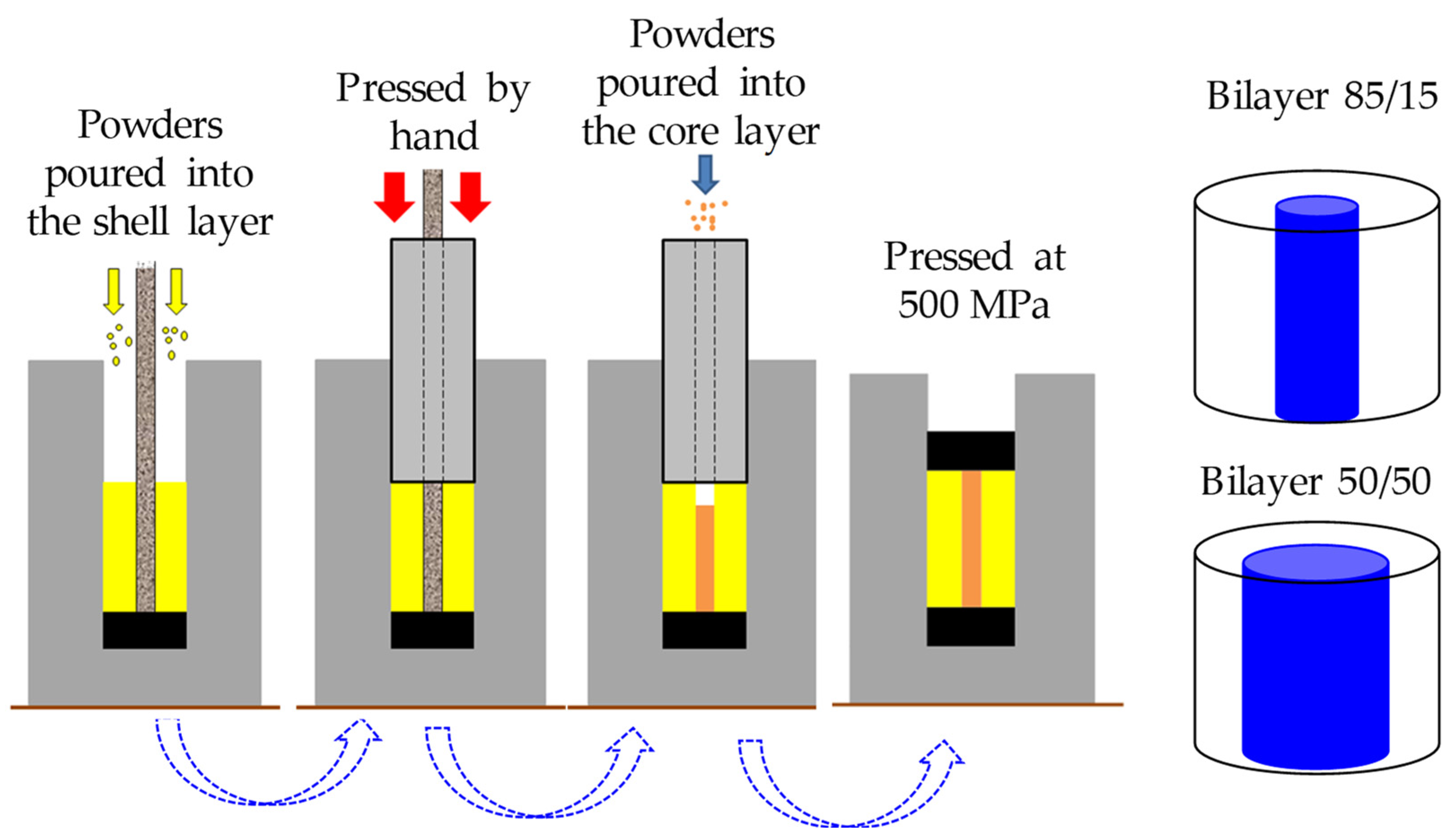
To obtain bilayer samples, stainless steel tubes of two different diameters, 3.0 and 5.66 mm, were placed at the center of the 8 mm diameter stainless steel die. The size of the diameter allowed there to be two ratios of volume in the whole sample corresponding to each layer, 85/15 and 50/50 for the outer layer and core, respectively. Different quantities of pores were obtained in the porous core by adding 30, 40, and 50% of salt particles. First, the Ti6Al4V powders filled the outer section to obtain a denser layer. Then, a punch was used to flatten the surface. Afterward, the mixture of Ti6Al4V and salt particles was poured inside the tubes, and both layers were then axially pressed at 500 MPa, as illustrated in Figure 2. The procedure to fabricate bilayer samples can be found elsewhere in more detail [45]. Afterward, the samples were pressed at 500 MPa. Finally, the salt was removed as described above.
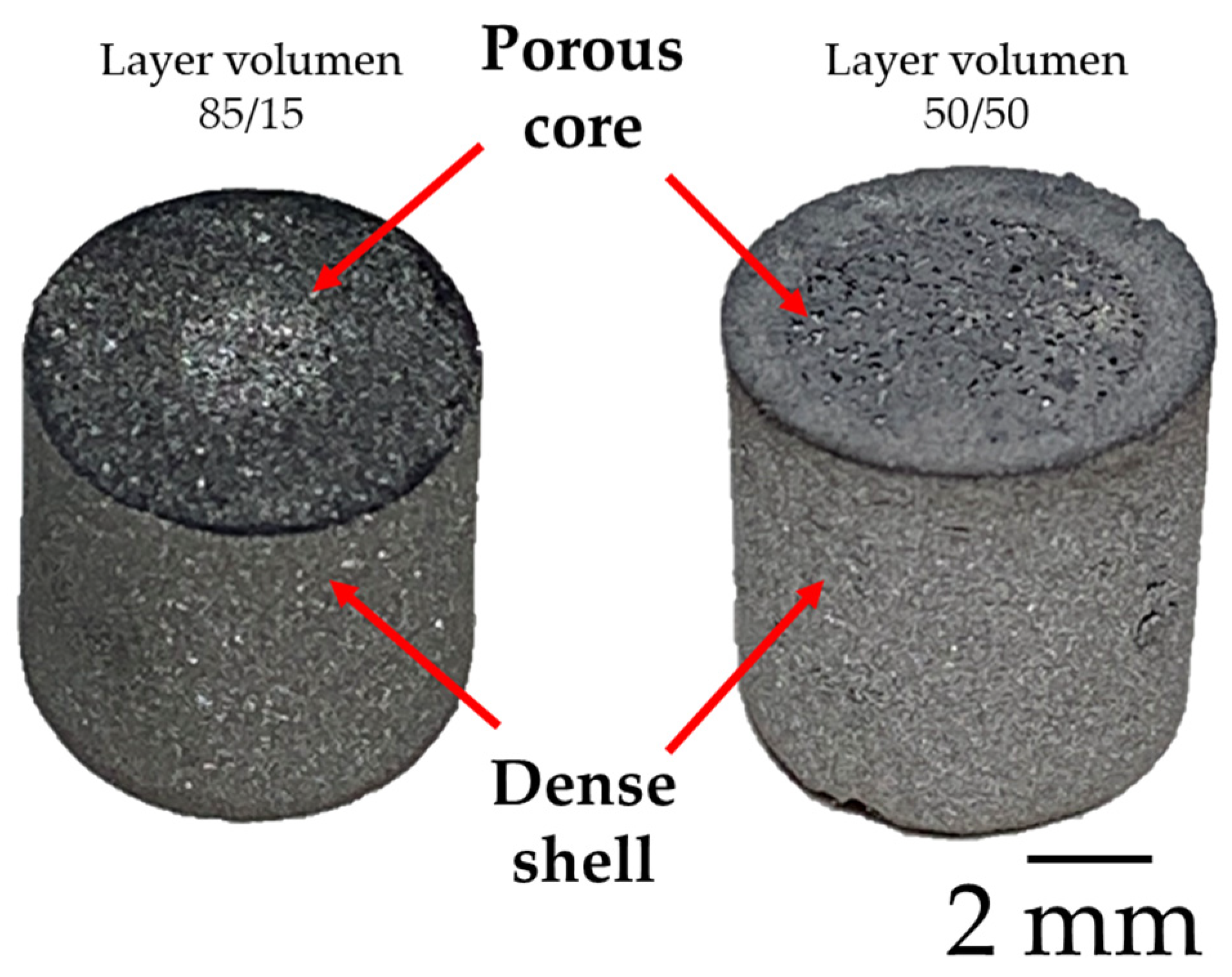
The sintering process of green samples was carried out in a Linseis L75V vertical dilatometer at 25 °C/min until reaching 1260 °C, remaining in argon atmosphere for 1 h. The dilatometer was purged to remove the air by flowing high-purity argon for 30 min before heating. After sintering, the relative density of samples was obtained by measuring the volume of samples and weighing them to obtain the pore volume fraction. Figure 3 shows an image of the samples after sintering, where it is possible to see the porous core from the surface.

2.3. Microstructure Characterization and Mechanical Evaluation

The sintered samples were cut and metallographically prepared with SiC abrasive paper and alumina powder to obtain a surface roughness (Ra) of 70 nm. The microstructure was observed with a field-emission scanning electron microscope (FE-SEM TESCAN ORSAY HOLDING, a.s., Brno-Kohoutovice, Czech Republic), Tescan MIRA 3 LMU, with a voltage of 20 keV.
A study of macroporosity was carried out using 3D images acquired via computerized microtomography (CMT) in a Zeiss Xradia 510 Versa 3D X-ray microtomograph Jena, Germany). In order to observe the 8 mm diameter Ti64 samples, an intensity of 120 kV was used. In total, 1600 projections were obtained around the samples in 360° with a CCD camera of 1025 × 1025 pixels. The resulting voxel size of approximately 9 μm allowed for observation of the entire sample. This resolution permitted an analysis of the pores created by the ammonium bicarbonate salt particles.
The 3D images were manually processed to obtain binary images at a constrained threshold based on the relative density, previously obtained from the actual mass and volume. Once the binary images were obtained, the solid and porous phases were represented with voxel intensities of 255 and 0, respectively. From the processed images, the porosity characteristics were obtained, such as the volume fraction, the size distribution, and the size of the channels, according to the process explained by L. Olmos et al. [33].
Simple compression tests were performed according to ASTM D695-02 [46] with an Instron 1150 universal testing machine; the strain rate was 0.5 mm/min. The elastic modulus (E) and the elastic limit (σy) were calculated from the load displacement data provided by the machine for triplicate samples. For stress calculation, a data correction was performed assuming that the volume was constant during the test; this assumption is reasonable for low strains where E and σy are estimated. With the aim to observe the dispersion of the data, three samples at each conditions were prepared and the average value as well as the standard deviation were estimated.
The flow properties of the porous samples were evaluated via numerical simulation of permeability using the Avizo® software version 2019 on the 3D reconstructed binary images obtained via tomography. To run the numerical simulations, a minimum representative volume (MRV) was obtained by selecting a 20 × 20 × 20 voxel volume cube from the center of the 3D image; then, the relative density for this volume was calculated. The operations carried out were repeated in 20 voxels per side of the cube until reaching a relatively constant relative density; a similar method was proposed by Okuma et al. [47]. To save numerical simulation time due to computational limitations, a minimum volume was calculated to obtain a maximum value of precision. A volume of 2503 voxels3 was obtained, in which the relative density reached an almost constant value; therefore, a volume of 300 × 300 × 300 voxels (20 mm3 of the real volume) was used for the numerical simulations that were performed. The numerical simulations were carried out in three directions, where the X and Y Cartesian axes were the horizontal planes and Z was the vertical axis.
With the aid of the Avizo® software, numerical simulations were performed based on Darcy’s law, solving the Navier–Stokes equations via the finite volume method. The simulation considered a Newtonian fluid in steady state, representing the blood, with a viscosity of 0.045 Pa·s. The pressure conditions used at the inlet and outlet were 130 and 100 kPa, respectively.

3. Results and Discussion

3.1. Dilatometry Analysis

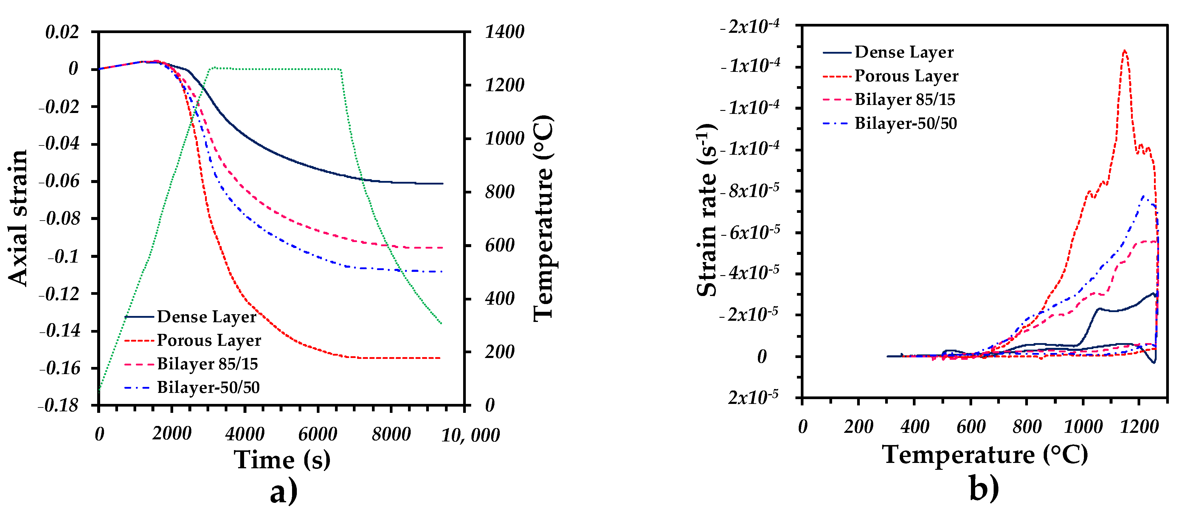
The axial strain during the sintering cycle of the monolayer and bilayer samples was plotted as a function of time and temperature (Figure 4a). The curves show an initial dilation until sintering was activated at 680 °C. Then, the slope of the curve changed to negative values, which indicates a shrinkage of the compacts with exponential behavior until the end of the isothermal stage. Finally, the stage of cooling added a small shrinkage due to the thermal contraction of the samples. It was found that the final strain was larger for the porous sample and that the one obtained for the bilayer was in the middle, between the porous and dense monolayer samples. It can also be noted that the shrinkage of the bilayer with a ratio of porous core to dense shell of 50/50 was larger than the one with a ratio of 85/15. This behavior indicates that densification was due to a combination of both layers. This can be confirmed by the strain rate of the bilayer samples, which increased as the diameter of the porous core decreased (see Figure 4b). A high strain rate was reached in the porous sample because of the macroscopic deformation caused by the sintering effects, and neck formation and growth, and the deformation of the large pores was due to the sintering stresses that developed as a result of the densification.
The relative densities of the samples after sintering are listed in Table 1, and as expected, the values of the bilayer samples were in between those of the monolayer samples that composed it. However, to establish if the relative density of the samples corresponded to the volume of each layer, the rule of mixtures was used. The rule of mixtures can be written as follows:
D b = f c   D c + f s   D s
where Db, Dc, and Ds represent the relative density of the bilayer, core, and shell samples, respectively. Dc and Ds were assumed to be the relative density of the monolayer samples obtained under the same fabrication conditions as those of the bilayer samples, and fc and fs represent the volume fraction of the core and shell samples, respectively. The volume fractions of the porous-core and dense-shell layers corresponded to 15 and 50% and 85 and 50%, respectively. It was found that all the relative densities estimated via the rule of mixtures were higher than the ones that were measured. This suggests that a greater interparticle porosity was obtained, which was generated by the stresses generated at the interface of both layers. Although this difference can be as high as 10 times between the porous and dense samples, the delamination of the core layer was not observed [44,48,49]. The larger ratios of the DR-M/D (see Table 1) found in the bilayer 85/15 samples indicate that the dense layer should be more affected by this effect. Therefore, the relative density of the bilayer was lower than the one predicted via the rule of mixtures.

3.2. Tomography Analysis

Virtual 2D slices of the bilayer samples showing the distribution of the large pores illustrate the interface between the porous core and the dense shell (Figure 5). Large pores were well located in the middle of the samples, and two different diameters could be distinguished. Because of the voxel resolution of the 3D images, it was not possible to observe the interparticle porosity remaining after sintering. Nevertheless, this analysis was more focused on the location of the large pores and on confirming that no fissures or delamination were found at the interface. It can also be qualitatively noticed that the strut size in the porous core reduced as the pore volume increased. A 3D rendering of the bilayer samples fabricated with 30 and 50 vol.% of salts and 85/15- and 50/50-diameter core ratios are shown in Figure 6a–d, respectively. It can be noticed that the core has a cylindrical shape that goes from top to bottom. Also, the connectivity of the pores is illustrated by a color code that indicates if large pores are connected to each other. As can be observed, the porosity that was created was fully interconnected, which was in agreement with that found for the monolithic porous samples [19].
The pore volume fraction in the porous core of the bilayer samples showed an increase with respect to the volume fraction of the pore formers used (see Table 2). This was mainly because the interaction of the pore-former particles induced an additional interparticle porosity. The pore size distribution of the porous core of the bilayer samples was estimated from the 3D images, and its values were very similar no matter the quantity of the pore formers used (Figure 7a). This suggests that the salt particles were randomly distributed without big agglomerates that could form larger pores. A wide pore size distribution from 50 to 580 µm was found (see Table 2), which corresponded to the size of the pore formers. The median pore size (d50) ranged from 168 to 184 µm (Table 2), indicating that the pore formers were surrounded by the Ti64 particles. On the contrary, the median strut size showed a reduction as the pore volume of the pore formers increased from 97 to 61 µm (see Table 2). This represents a reduction of 38% for an increase in the pore volume of 44%, indicating a linear behavior for the strut size with respect to the pore volume fraction. The pore and strut sizes of the scaffolds fabricated in this study were lower than those obtained in the scaffolds fabricated using additive manufacturing (AM), which ranged from 350 to 1400 µm for the pores and 466 to 941 µm for the struts depending on the AM technique used [50,51,52]. However, the pore size distribution was suitable to allow for cell adhesion and the formation of the mineralization tissues that lead to bone ingrowth [53,54,55].
The permeability was estimated from the numerical simulations of the 3D microstructure issued from the porous core, and the values are listed in Table 2. As expected, the permeability increased as the volume fraction increased. The behavior corresponded to a cubic power law with respect to the pore volume fraction, as is shown in Figure 5b. This is consistent with the different models proposed to estimate permeability based on the Kozeny–Carman model [56,57]. A more tortuous path for the samples with a 30 vol.% of pore formers can also be noted from the flow lines in comparison to the ones with a 50 vol.% of pore formers (Figure 6e,f). This confirms the reduction in the tortuosity that was measured from the 3D images and listed in Table 2. The permeability values were also in the range of that reported for human bones. For example, permeability ranges from 3 × 10⁻¹¹ to 5 × 10⁻¹⁰ m2 for human proximal femurs and from 10−8 to 10−9 m2 for human vertebral bodies, according to Nauman et al. [34].

3.3. Mechanical Strength Analysis

The compression behavior of the bilayer samples is shown in the stress–strain curves in Figure 8a. As a reference, the monolithic samples are also plotted. As expected, the strength decreased as the pore formers and the core diameter increased. It can also be noticed that the ductility was reduced because the strain of the bilayer was reduced due to the effect of the dense shell. The elastic modulus (E) and the yield stress (σy) were estimated from the elastic part of the curves in Figure 8a, and the values are listed in Table 3. The monolithic samples showed a large reduction as the pore volume increased, showing the lowest value of E, 0.32 GPa, and σy, 9.7 MPa. However, the values of E that were deduced from the stress–strain curves should be taken with caution because they were frequently underestimated in comparison to the ones reported via the ultrasonic method [58]. The E values of the bilayer samples also showed a reduction that showed an exponential behavior as a function of the ratio of the surface of the porous core to that of the dense shell (Figure 8b). The reduction in the mechanical properties was similar to the one reported by Gryko et al. [59], who evaluated this value via finite element numerical simulations on materials designed via AM with different pore shapes. On the other hand, the behavior of the radial bilayer samples reported by Ahmadi and Sadrnezhaad showed a lineal behavior [44], whose values are also plotted in Figure 8b for comparison. It can be seen that lower values were obtained in this work for similar porous-core diameters, which was due to the quantity of pores generated by the pore formers. The E value was estimated using the rule of mixtures, as performed above for the density, with the aim to understand the behavior of the samples under compression. The rule of mixtures can be rewritten as follows:
E b = f c   E c + f s   E s
where Eb, Ec, and Es are the elastic modulus of the bilayer, core, and shell samples, respectively. Ec and Es were assumed to be the E of the monolayer samples obtained under the same fabrication conditions as the bilayer samples, and fc and fs are the volume fraction of the core and shell samples, respectively. The ER-M values were higher than those measured from the stress–strain curves (see Table 3). This was consistent with the values of the relative density estimated via the rule of mixtures; however, the ER-M/E ratio was larger than that obtained from the density.
On the other hand, the σy values of the bilayer samples also showed a reduction as the core diameter increased, which was as expected. Nevertheless, the behavior was close to linear instead of the exponential behavior found for E. σy was also estimated via the rule of mixtures as was performed for E:
σ y b = f c   σ y c + f s   σ y s
where σyb, σyc, and σys represent the yield stress of the bilayer, core, and shell samples, respectively. σyc and σys were assumed to be the σy of the monolayer samples listed in Table 3. It was also found that the rule of mixtures overestimated the measured σy; however, the σyR-My ratio was close to one. This indicates that σy followed a linear trend since the rule of mixtures is a linear equation. In addition, the admissible strain (σy/E), which should be as high as possible to improve the mechanical behavior of a bone implant, as suggested in [60], is also shown in Table 3. The values were from 10 × 10−3 to 43 × 10−3, the highest being the value for the bilayer of 50/50 P50. These values were in the range reported for human bones (from 0.011 for compact bone to 0.035 for trabecular vertebrae) [1].
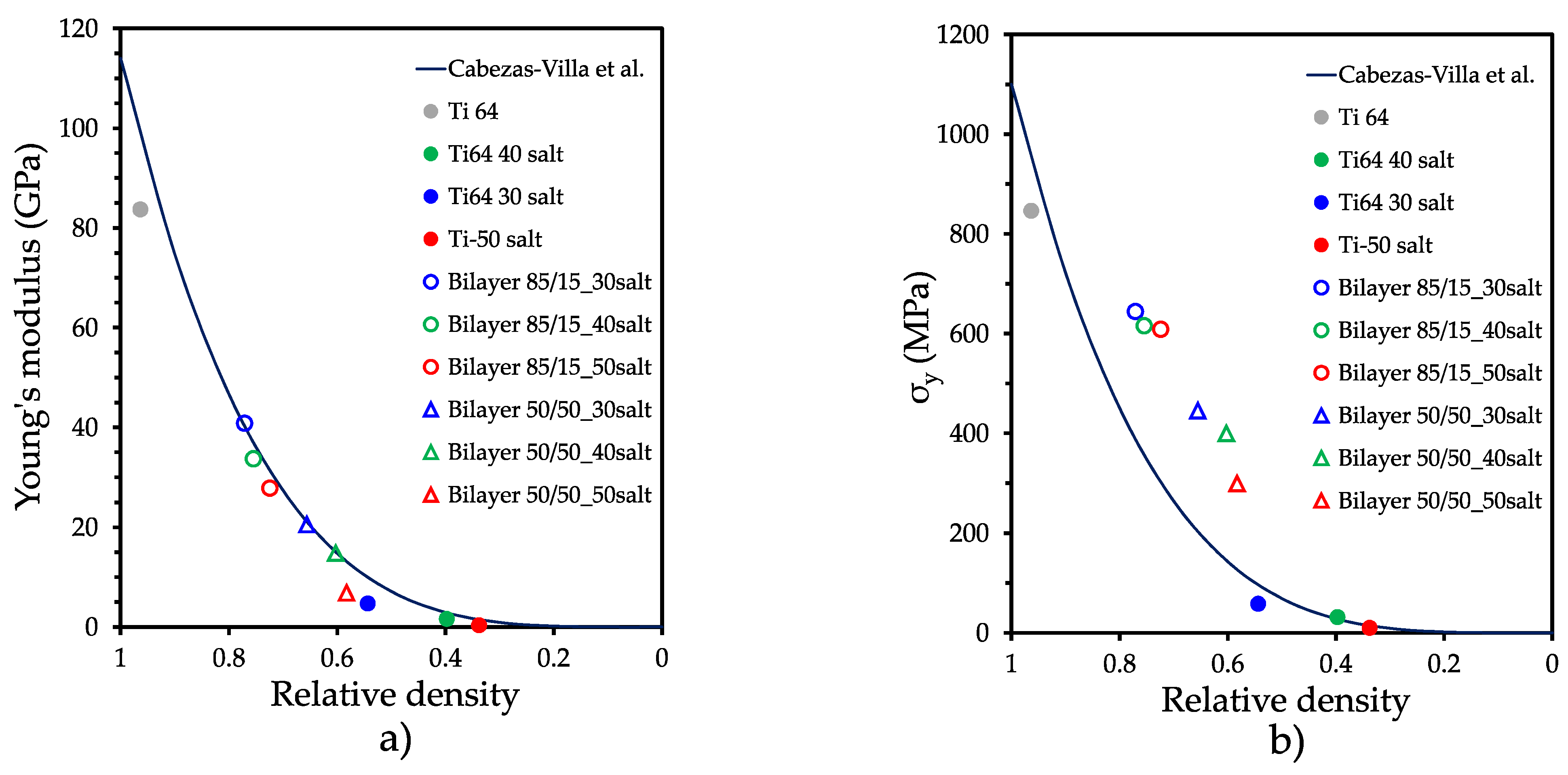
Different models have been proposed to predict the elastic modulus of porous materials as a function of the pore volume fraction [22,23,24,61]. Some of them consider the pore shape by introducing shape factors that are generally measured from 2D postmortem images, which makes it difficult to englobe the different porous materials. Cabezas et al. [18] found that the Gibson and Ashby [22] power law can accurately predict E values by fitting the exponent of the power law to be four instead of the original two that was proposed, resulting in the following equation:
  E = E 0 D 4
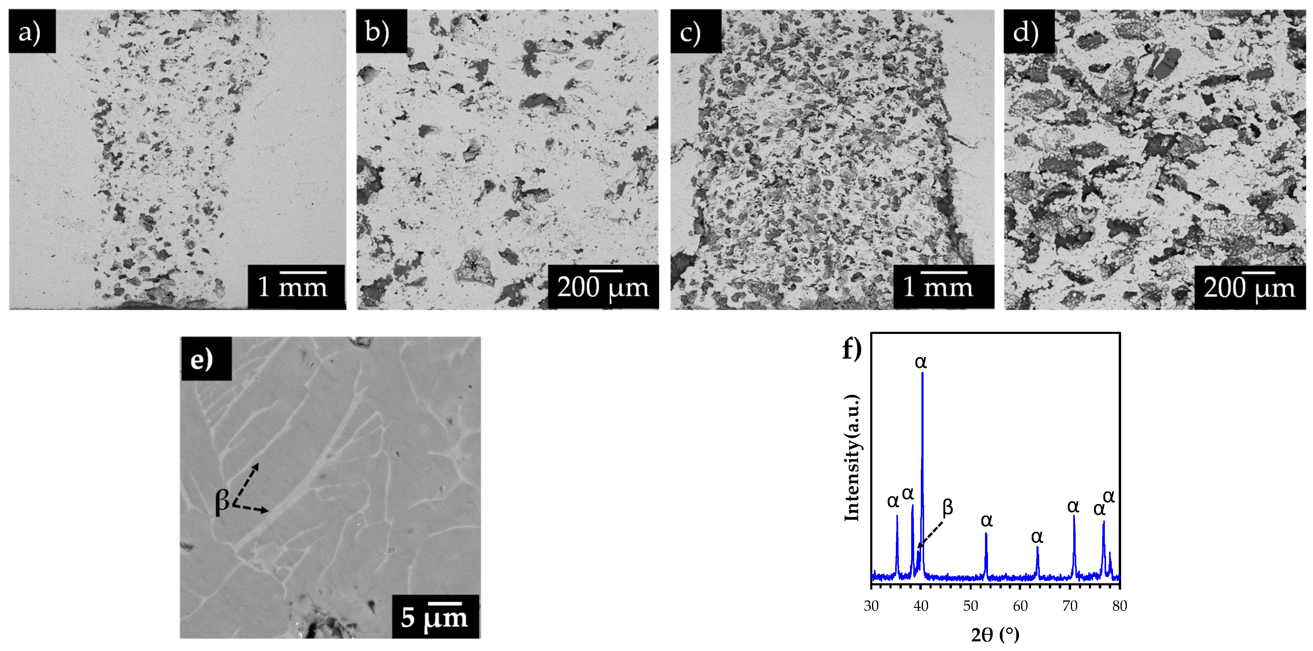
where E0 is the elastic modulus of the fully dense materials. Thus, the E values of the monolayer and bilayer samples are depicted in Figure 9a, and a good accuracy for predicting the E values was found with the model by considering the relative density. This could suggest that the stiffness of the bilayer samples was driven by the porosity of the samples. This could be confirmed from the fractured images shown in Figure 10, in which pore closure in the core layer could occur during the deformation process. It can also be seen that the fracture showed a 45° angle formed at the shell, Figure 10a,c, no matter the core diameter nor the pore volume fraction.
On the contrary, the values of σy for the bilayer samples did not follow the behavior estimated for the same power law proposed in [18]. These values were much higher, which suggests that σy was more dependent on the dense shell. This could confirm that the stiffness and strength of the bilayer samples cannot be estimated simply by the rule of mixtures since the interaction of both layers played a role in the mechanical behavior in which the deformation of the pores gave more elasticity, as can be seen in the fractured images in Figure 10b,d. Meanwhile, the dense shell gave a high resistance, as suggested by the fracture path in Figure 10a,c. This analysis assumes that the microstructure of samples is composed of the typical α + β lamellar in both porous and dense layers. Figure 10e illustrates the configuration of the β lamellae inside the α grains, which is obtained after sintering of the samples. Moreover, Figure 10f shows the X-ray pattern of the samples in which the α phase is predominant, although the main peak of the β phase is also detected. Therefore, the mechanical properties are mainly associated with the induced porosity in the samples.
From the results obtained and discussed above, it can be said that the bilayer samples with a volume ratio of core to shell of 50/50 and beyond can be used for bone implants since their microstructure, permeability, and mechanical characteristics can better mimic those of human bones.

4. Conclusions

A pressing and sintering process was successfully developed to fabricate porous-core materials that mimic the microstructure of human bones. The main findings are as follows:
No cracks were formed during sintering because the porous core and the dense shell were composed of the same kind of particles, which generated interparticle bonds at the interface of both layers.
The stiffness of the bilayer components was driven by the porous core, while their strength resulted from the combination of both layers. This gave materials their permeability and mechanical properties as well as a high admissible strain (σy/E) similar to that of human bones.
To specifically obtain the mechanical or permeability values, the quantity of pores or the porous-core diameter should be adjusted for optimization according to the proposed power law.

Author Contributions

Conceptualization, L.O.; methodology, R.M.; project administration, P.G.; supervision, P.G. and L.O.; writing—original draft, formal analysis, L.O., R.M. and I.A.; investigation, L.O., D.B. and R.M. writing—review and editing, O.J.; validation, D.B., J.C., L.O. and I.A.; visualization; image processing, C.M.-B. and L.O.; methodology, J.L.C.-V. All authors have read and agreed to the published version of the manuscript.

Funding

This research was supported by the National Council of Humanities, Science and Technology CONAHCYT during the postdoctoral stage of R. Macias and I. Alanis; grant numbers CVU 789772 and CVU 737815. It was also supported by the ICTY in the PICIR 2023 projects announcement.

Institutional Review Board Statement

Not applicable.

Informed Consent Statement

Not applicable.

Data Availability Statement

Data are contained within the article.

Acknowledgments

The authors want to thank the contribution of Dante Arteaga of the LUMIR Geosciences laboratory of UNAM, Juriquilla, to 3D image acquisition and processing.

Conflicts of Interest

The authors declare no conflict of interest.

References

  1. Wang, X.; Xu, S.; Zhou, S.; Xu, W.; Leary, M.; Choong, P.; Qian, M.; Brandt, M.; Xie, Y.M. Topological design and additive manufacturing of porous metals for bone scaffolds and orthopaedic implants: A review. Biomaterials 2016, 83, 127–141. [Google Scholar] [CrossRef]
  2. Murr, L.E.; Gaytan, S.M.; Martinez, E.; Medina, F.; Wicker, R.B. Next generation orthopaedic implants by additive manufacturing using electron beam melting. Int. J. Biomater. 2012, 2012, 245727. [Google Scholar] [CrossRef]
  3. Chen, Q.Z.; Thompson, I.D.; Boccaccini, A.R. 45S5 Bioglass®-derived glass–ceramic scaffolds for bone tissue engineering. Biomaterials 2006, 27, 2414–2425. [Google Scholar] [CrossRef]
  4. Bandyopadhyay, A.; Mitra, I.; Avila, J.D.; Upadhyayula, M.; Bose, S. Porous metal implants: Processing, properties, and challenges. Int. J. Extreme Manuf. 2023, 5, 032014. [Google Scholar] [CrossRef]
  5. Russell Levive, B.; Spoere, S.; Poggie, R.A.; Della Valle, C.J.; Jacobs, J.J. Experimental and clinical performance of porous tantalum in orthopaedic surgery. J. Biomater. 2006, 27, 4671–4681. [Google Scholar] [CrossRef]
  6. España, F.A.; Balla, V.K.; Bose, S.; Bandyopadhyay, A. Design and fabrication of CoCrMo alloy based novel structures for load bearing implants using laser engineered net shaping. Mater. Sci. Eng. C 2010, 30, 50–57. [Google Scholar] [CrossRef]
  7. Bansiddhi, A.; Sargeant, T.D.; Stupp, S.I.; Dunand, D.C. Porous NiTi for bone implants: A review. Acta Biomater. 2008, 4, 773–782. [Google Scholar] [CrossRef]
  8. Ballarre, J.; Manjubala, I.; Schreiner, W.H.; Orellano, J.C.; Fratzl, P.; Ceré, S. Improving the osteointegration and bone–implant interface by incorporation of bioactive particles in sol–gel coatings of stainless-steel implants. Acta Biomater. 2010, 6, 1601–1609. [Google Scholar] [CrossRef]
  9. Shirazi, S.F.S.; Gharehkhani, S.; Mehrali, M.; Yarmand, H.; Metselaar, H.S.C.; Kadri, N.A.; Osman, N.A.A. A review on powder-based additive manufacturing for tissue engineering: Selective laser sintering and inkjet 3D printing. Sci. Technol. Adv. 2015, 16, 033502. [Google Scholar] [CrossRef]
  10. Dumas, M.; Terriault, P.; Brailovski, V. Modelling and characterization of a porosity graded lattice structure for additively manufactured biomaterials. Mater. Des. 2017, 121, 383–392. [Google Scholar] [CrossRef]
  11. Zhang, C.; Zhang, L.; Liu, L.; Lv, L.; Gao, L.; Liu, N.; Wang, X.; Ye, J. Mechanical behavior of a titanium alloy scaffold mimicking trabecular structure. J. Orthop. Surg. Res. 2020, 15, 40. [Google Scholar] [CrossRef]
  12. Liu, G.; Zhang, X.; Chen, X.; He, Y.; Cheng, L.; Huo, M.; Yin, J.; Hao, F.; Chen, S.; Wang, P.; et al. Additive manufacturing of structural materials. Mater. Sci. Eng. R Rep. 2021, 145, 100596. [Google Scholar] [CrossRef]
  13. Arifvianto, B.; Zhou, J. Fabrication of metallic biomedical scaffolds with the space holder method: A review. Materials 2014, 7, 3588–3622. [Google Scholar] [CrossRef]
  14. Reig, L.; Amigó, V.; Busquets, D.J.; Calero, J.A. Development of porous Ti6Al4V samples by microsphere sintering. Mater. Process. Technol. 2012, 212, 3–7. [Google Scholar] [CrossRef]
  15. Torres, Y.; Rodríguez, J.A.; Arias, S.; Echeverry, M.; Robledo, S.; Amigo, V.; Pavón, J.J. Processing, characterization and biological testing of porous titanium obtained by space-holder technique. J. Mater. Sci. 2012, 47, 6565–6576. [Google Scholar] [CrossRef]
  16. Zhang, E.; Zhao, X.; Hu, J.; Wang, R.; Fu, S.; Qin, G. Antibacterial metals and alloys for potential biomedical implants. Bioact. Mater. 2021, 6, 2569–2612. [Google Scholar] [CrossRef]
  17. Chen, L.-Y.; Cui, Y.-W.; Zhang, L.-C. Recent Development in Beta Titanium Alloys for Biomedical Applications. Metals 2020, 10, 1139. [Google Scholar] [CrossRef]
  18. Cabezas-Villa, J.L.; Olmos, L.; Bouvard, D.; Lemus-Ruiz, J.; Jiménez, O. Processing and properties of highly porous Ti6Al4V mimicking human bones. Mater. Res. 2018, 33, 650–661. [Google Scholar] [CrossRef]
  19. Anene, F.A.; Aiza Jaafar, C.N.; Zainol, I.; Azmah Hanim, M.A.; Suraya, M.T. Biomedical materials: A review of titanium based alloys. Proc. Inst. Mech. Eng. C J. Mech. Eng. Sci. 2021, 235, 3792–3805. [Google Scholar] [CrossRef]
  20. Jakubowicz, J.; Adamek, G.; Dewidar, M. Titanium foam made with saccharose as a space holder. J. Porous Mater. 2013, 20, 1137–1141. [Google Scholar] [CrossRef]
  21. Bahraminasab, M.; Sahari, B.B.; Edwards, K.L.; Farahmand, F.; Arumugam, M.; Hong, T.S. Aseptic loosening of femoral components–a review of current and future trends in materials used. Mater. Des. 2012, 42, 459–470. [Google Scholar] [CrossRef]
  22. Gibson, L.J.; Ashby, M.F. Cellular Solids: Structure and Properties, 2nd ed.; Cambridge University Press: Cambridge, UK, 1999; p. 175. [Google Scholar]
  23. Phani, K.K.; Niyogi, S.K. Young’s modulus of porous brittle solids. J. Mater. Sci. 1987, 22, 257–263. [Google Scholar] [CrossRef]
  24. Nielsen, L.F. Elasticity and damping of porous materials and impregnated materials. J. Am. Ceram. Soc. 1984, 67, 93–98. [Google Scholar] [CrossRef]
  25. Breme, J.; Wadewitz, V. Comparison of titanium-tantalum and titanium-niobium alloys for application as dental implants . Int. J. Oral Maxillofac. Implant. 1989, 4, 113–118. [Google Scholar]
  26. Woodard, J.R.; Hilldore, A.J.; Lan, S.K.; Park, C.J.; Morgan, A.W.; Eurell, J.A.C.; Clark, S.G.; Wheeler, M.B.; Jamison, R.D.; Johnson, A.J.W. The mechanical properties and osteoconductivity of hydroxyapatite bone scaffolds with multi-scale porosity. Biomaterials 2007, 28, 45–54. [Google Scholar] [CrossRef] [PubMed]
  27. Takemoto, M.; Fujibayashi, S.; Neo, M.; Suzuki, J.; Kokubo, T.; Nakamura, T. Mechanical properties and osteoconductivity of porous bioactive titanium. Biomaterials 2005, 26, 6014–6023. [Google Scholar] [CrossRef] [PubMed]
  28. Dabrowski, B.; Swieszkowski, W.; Godlinski, D.; Kurzydlowski, K.J. Highly porous titanium scaffolds for orthopaedic applications. ACS Appl. Biomater. B 2010, 95, 53–61. [Google Scholar] [CrossRef]
  29. Wang, C.A.; Le, H.; Huang, Y. Rapid assembly processes of ordered inorganic/organic nanocomposites. In Biomimetics: Learning from Nature; Books on Demand: Norderstedt, Germany, 2010; pp. 1–24. [Google Scholar]
  30. Kienapfel, H.; Sprey, C.; Wilke, A.; Griss, P. Implant fixation by bone ingrowth. J. Arthroplast. 1999, 14, 355–368. [Google Scholar] [CrossRef]
  31. Singh, R.; Lee, P.D.; Lindley, T.C.; Dashwood, R.J.; Ferrie, E.; Imwinkelried, T. Characterization of the structure and permeability of titanium foams for spinal fusion devices. Acta Biomater. 2009, 5, 477–487. [Google Scholar] [CrossRef]
  32. Varley, M.C.; Neelakantan, S.; Clyne, T.W.; Dean, J.; Brooks, R.A.; Markaki, A.E. Cell structure, stiffness and permeability of freeze-dried collagen scaffolds in dry and hydrated states. Acta Biomater. 2016, 33, 166–175. [Google Scholar] [CrossRef]
  33. Olmos, L.; Bouvard, D.; Cabezas-Villa, J.L.; Lemus-Ruiz, J.; Jiménez, O.; Arteaga, D. Analysis of compression and permeability behavior of porous Ti6Al4V by computed microtomography. Met. Mater. Int. 2019, 25, 669–682. [Google Scholar] [CrossRef]
  34. Nauman, E.A.; Fong, K.E.; Keaveny, T.M. Dependence of intertrabecular permeability on flow direction and anatomic site. Ann. Biomed. Eng. 1999, 27, 517–524. [Google Scholar] [CrossRef] [PubMed]
  35. Wu, Y.C.; Kuo, C.N.; Wu, T.H.; Liu, T.Y.; Chen, Y.W.; Guo, X.H.; Huang, J.C. Empirical rule for predicting mechanical properties of Ti-6Al-4V bone implants with radial-gradient porosity bionic structures. Mater. Today Commun. 2021, 27, 102346. [Google Scholar] [CrossRef]
  36. Davoodi, E.; Montazerian, H.; Esmaeilizadeh, R.; Darabi, A.C.; Rashidi, A.; Kadkhodapour, J.; Ahed, H.; Hoorfar, M.; Milani, A.S.; Weiss, P.S.; et al. Additively manufactured gradient porous Ti–6Al–4V hip replacement implants embedded with cell-laden gelatin methacryloyl hydrogels. ACS Appl. Mater. Interfaces 2021, 13, 22110–22123. [Google Scholar] [CrossRef] [PubMed]
  37. Koju, N.; Niraula, S.; Fotovvati, B. Additively Manufactured Porous Ti6Al4V for Bone Implants: A Review. Metals 2022, 12, 687. [Google Scholar] [CrossRef]
  38. Li, X.; Xiong, Y.Z.; Zhang, H.; Gao, R.N. Development of functionally graded porous titanium/silk fibroin composite scaffold for bone repair. Mater. Lett. 2021, 282, 128670. [Google Scholar] [CrossRef]
  39. Wang, S.; Liu, L.; Li, K.; Zhu, L.; Chen, J.; Hao, Y. Pore functionally graded Ti6Al4V scaffolds for bone tissue engineering application. Mater. Des. 2019, 168, 107643. [Google Scholar] [CrossRef]
  40. Xiong, Y.Z.; Gao, R.N.; Zhang, H.; Dong, L.L.; Li, J.T.; Li, X. Rationally designed functionally graded porous Ti6Al4V scaffolds with high strength and toughness built via selective laser melting for load-bearing orthopedic applications. J. Mech. Behav. Biomed. Mater. 2020, 104, 103673. [Google Scholar] [CrossRef]
  41. Yu, G.; Li, Z.; Li, S.; Zhang, Q.; Hua, Y.; Liu, H.; Zhao, X.; Dhaidhai, D.T.; Li, W.; Wang, X. The select of internal architecture for porous Ti alloy scaffold: A compromise between mechanical properties and permeability. Mater. Des. 2020, 192, 108754. [Google Scholar] [CrossRef]
  42. Dewidar, M.M.; Lim, J.K. Properties of solid core and porous surface Ti–6Al–4V implants manufactured by powder metallurgy. J. Alloys Compd. 2008, 454, 442–446. [Google Scholar] [CrossRef]
  43. Lee, J.H.; Park, H.J.; Hong, S.H.; Kim, J.T.; Lee, W.H.; Park, J.M.; Kim, K.B. Characterization and deformation behavior of Ti hybrid compacts with solid-to-porous gradient structure. Mater. Des. 2014, 60, 66–71. [Google Scholar] [CrossRef]
  44. Ahmadi, S.; Sadrnezhaad, S.K. A novel method for production of foamy core@ compact shell Ti6Al4V bone-like composite. J. Alloys Compd. 2016, 656, 416–422. [Google Scholar] [CrossRef]
  45. Olmos, L.; Mihalcea, E.; Vergara-Hernández, H.J.; Bouvard, D.; Jimenez, O.; Chávez, J.; Camacho, N.; Macías, R. Design of architectured Ti6Al4V-based materials for biomedical applications fabricated via powder metallurgy. Mater. Today Commun. 2021, 29, 102937. [Google Scholar] [CrossRef]
  46. ASTM D695-02; Standard Test Method for Compressive Properties of Rigid Plastics. ASTM: West Conshohocken, PA, USA, 2002.
  47. Okuma, G.; Kadowaki, D.; Shinoda, Y.; Akatsu, T.; Guillon, O.; Wakai, F. Determination of the size of representative volume element for viscous sintering. JCS 2016, 124, 421–425. [Google Scholar] [CrossRef]
  48. Trueba, P.; Chicardi, E.; Rodríguez-Ortiz, J.A.; Torres, Y. Development and implementation of a sequential compaction device to obtain radial graded porosity cylinders. J. Manuf. Process. 2020, 50, 142–153. [Google Scholar] [CrossRef]
  49. Cocks, A.C. Constitutive modelling of powder compaction and sintering. Prog. Mater. Sci. 2001, 46, 201–222. [Google Scholar] [CrossRef]
  50. Parthasarathy, J.; Starly, B.; Raman, S.; Christensen, A. Mechanical evaluation of porous titanium (Ti6Al4V) structures with electron beam melting (EBM). Mech. Behav. Biomed. Mater. 2010, 3, 249–259. [Google Scholar] [CrossRef]
  51. Sallica-Leva, E.; Jardini, A.L.; Fogagnolo, J.B. Microstructure and mechanical behavior of porous Ti–6Al–4V parts obtained by selective laser melting. Mech. Behav. Biomed. Mater. 2013, 26, 98–108. [Google Scholar] [CrossRef]
  52. Coffigniez, M.; Gremillard, L.; Balvay, S.; Lachambre, J.; Adrien, J.; Boulnat, X. Direct-ink writing of strong and biocompatible titanium scaffolds with bimodal interconnected porosity. Addit. Manuf. 2021, 39, 101859. [Google Scholar] [CrossRef]
  53. Itälä, A.I.; Ylänen, H.O.; Ekholm, C.; Karlsson, K.H.; Aro, H.T. Pore diameter of more than 100 μm is not requisite for bone ingrowth in rabbits. J. Biomed. Mater. Res. 2001, 58, 679–683. [Google Scholar] [CrossRef]
  54. Taniguchi, N.; Fujibayashi, S.; Takemoto, M.; Sasaki, K.; Otsuki, B.; Nakamura, T.; Matsuda, T.; Kokubo, T.; Matsuda, S. Effect of pore size on bone ingrowth into porous titanium implants fabricated by additive manufacturing: An in vivo experiment. Mater. Sci. Eng. C 2016, 59, 690–701. [Google Scholar] [CrossRef]
  55. Bohner, M.; Baroud, G.; Bernstein, A.; Doebelin, N.; Galea, L.; Hesse, B.; Heuberger, R.; Meille, S.; Michel, P.; von Rechenberg, B.; et al. Characterization and distribution of mechanically competent mineralized tissue in micropores of β-tricalcium phosphate bone substitutes. Today Commun. 2017, 20, 106–115. [Google Scholar] [CrossRef]
  56. Kaviany, M. Principles of Heat Transfer in Porous Media; Springer: New York, NY, USA, 1995. [Google Scholar]
  57. Katz, A.J.; Thompson, A.H. Quantitative prediction of permeability in porous rock. Phys. Rev. B 1986, 34, 8179. [Google Scholar] [CrossRef]
  58. Torres, Y.; Lascano, S.; Bris, J.; Pavón, J.; Rodriguez, J.A. Development of porous titanium for biomedical applications: A comparison between loose sintering and space-holder techniques. Mater. Sci. Eng. C 2014, 37, 148–155. [Google Scholar] [CrossRef] [PubMed]
  59. Gryko, A.; Prochor, P.; Sajewicz, E. Finite element analysis of the influence of porosity and pore geometry on mechanical properties of orthopaedic scaffolds. J. Mech. Behav. Biomed. Mater. 2022, 132, 105275. [Google Scholar] [CrossRef] [PubMed]
  60. Song, Y.; Xu, D.S.; Yang, R.; Li, D.; Wu, W.T.; Guo, Z.X. Theoretical study of the effects of alloying elements on the strength and modulus of β-type bio-titanium alloys. Mater. Sci. Eng. A 1999, 260, 269–274. [Google Scholar] [CrossRef]
  61. Kováčik, J. Correlation between Young’s modulus and porosity in porous materials. J. Mater. Sci. Lett. 1999, 18, 1007–1010. [Google Scholar] [CrossRef]
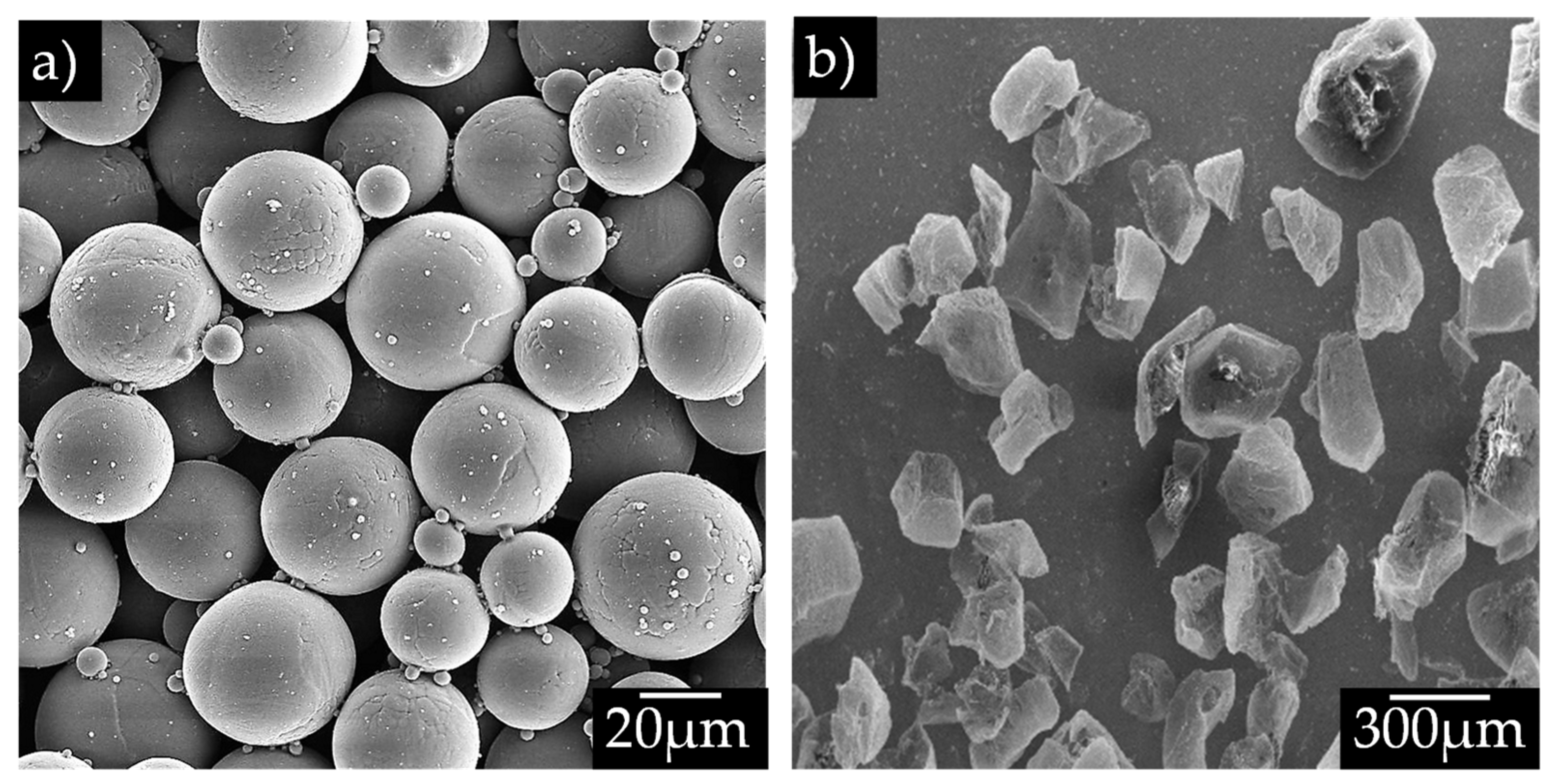
Figure 1. (a) Prealloyed Ti6Al4V spherical powder and (b) ammonium bicarbonate salt ((NH4)HCO3).
Coatings 14 00065 g001
Figure 2. Schematic of the bilayer-component-processing steps.
Coatings 14 00065 g002
Figure 3. Real sintered samples with 15/85 and 50/50 ratios of volume per layer, respectively.
Coatings 14 00065 g003
Figure 4. Dilatometry of the bilayers of Ti6Al4V samples: (a) axial strain (dimensionless unit) and (b) strain rate.
Coatings 14 00065 g004
Figure 5. Two-dimensional virtual slices of bilayer samples: (a,b) show porous cores with 30% volume of pore formers, and (c,d) show porous cores with 50% volume of pore formers.
Coatings 14 00065 g005
Figure 6. Rendered 3D images of bilayer samples and simulated flow paths in the porous core: (a,b,e) show porous cores with 30% volume of pore formers, and (c,d,f) show porous cores with 50% volume of pore formers.
Coatings 14 00065 g006aCoatings 14 00065 g006b
Figure 7. (a) Pore and strut size distributions (dimensionless unit) and (b) permeability as a function of the pore volume fraction of the porous-core layer with different volume fractions of bilayer samples.
Coatings 14 00065 g007
Figure 8. Stress–strain compression curves of bilayer samples with different ratios of porous-core diameters (a) and Young’s modulus as a function of the surface ratio of core to shell layer (b) [44].
Coatings 14 00065 g008
Figure 9. (a) Young’s modulus and (b) yield stress as a function of the relative density (dimensionless unit) [18].
Coatings 14 00065 g009
Figure 10. SEM images of the fractured samples after compression tests: (a,b) Show porous cores with 30% volume of pore formers, and (c,d) show porous cores with 50% volume of pore formers. (e) Backscattering image at higher magnification to show the microstructure and (f) XRD pattern of sintered samples.
Coatings 14 00065 g010
Table 1. Relative density measured and estimated via the rule of mixtures (R-M).
SampleRelative Density (D)Relative Density (R-M)Ratio DR-M/D
Ti6Al4V P00.9633 ± 8 × 10⁻³--
Ti6Al4V P300.5436 ± 1 × 10⁻²--
Ti6Al4V P400.3972 ± 2 × 10⁻²--
Ti6Al4V P500.3378 ± 2 × 10⁻²--
Bilayer 85/15 P300.7706 ± 3 × 10−20.90431.17
Bilayer 85/15 P400.7544 ± 4 × 10−20.88371.17
Bilayer 85/15 P500.7238 ± 3 × 10−20.87531.20
Bilayer 50/50 P300.6557 ± 6 × 10−20.75321.14
Bilayer 50/50 P400.6026 ± 4 × 10−20.68001.12
Bilayer 50/50 P500.5827 ± 5 × 10−20.65021.11
Table 2. Pore characteristics of the porous-core layers fabricated with different quantities of pore formers.
Volume Fraction of Pore Formers (%)Pore Volume
Fraction (%)
Median Pore Size (d50 µm)Median Strut Size (d50 µm)Permeability
(m2 ×10−10)
Tortuosity
3032.32 ± 1174.1097.120.19 ± 8 × 10−21.82
4042.50 ± 2168.3682.260.47 ± 9 × 10−21.58
5057.26 ± 2184.7961.271.36 ± 1 × 10−11.37
Table 3. Mechanical properties of monolayer and bilayer samples.
SampleE (GPa)ER-M (GPa)ER-M/Eσy (MPa)σyR-M (MPa)σyR-M/σyσy/E (10−3)
Ti6Al4V P083.7 ± 3.01-- 846.5 10.11
Ti6Al4V P304.7 ± 0.16-- 58 12.34
Ti6Al4V P401.6 ± 0.05-- 31.3 19.56
Ti6Al4V P500.32 ± 0.01-- 9.7 30.31
Bilayer 85/15 P3040.8 ± 1.4772.591.77643.9735.611.1415.78
Bilayer 85/15 P4033.7 ± 1.2144.152.15445.5451.811.0121.73
Bilayer 85/15 P5027.8 ± 1.0072.152.14615.5731.861.1818.26
Bilayer 50/50 P3020.5 ± 0.7342.602.87399.8438.441.0927.01
Bilayer 50/50 P4014.8 ± 0.5371.972.58608.5728.821.1921.88
Bilayer 50/50 P506.83 ± 0.2442.606.23299438.441.4643.77
Disclaimer/Publisher’s Note: The statements, opinions and data contained in all publications are solely those of the individual author(s) and contributor(s) and not of MDPI and/or the editor(s). MDPI and/or the editor(s) disclaim responsibility for any injury to people or property resulting from any ideas, methods, instructions or products referred to in the content.