Abstract
The longevity of thermally sprayed ceramic coatings is often difficult to achieve in corrosive environments. In this paper, an alternating sealing coating technology was used to seal supersonic plasma sprayed Al2O3 coatings. Scanning electron microscopy (SEM) and X-ray diffraction (XRD) were used to characterize the coating microstructure of Al2O3 coatings and seal coats. The corrosion behavior of alternating sealing coating, traditional sealed coating, and spray coating at 5 wt.% NaCl was studied by the electrochemical test method (dynamic polarization) and immersion corrosion experiments. The results show that the alternating sealing coating is better in preventing the production of through holes and hindering the inward diffusion of corrosive media than traditional sealed coatings, and further increases the thickness of the sealing layer. Compared with the traditional sealing coating, the porosity of alternating sealing coating is decreased by 70.5%, the corrosion potential is increased by 74 mV, and the corrosion current density is decreased by about 78%, which confers better long-term corrosion resistance.
1. Introduction
Thermal spraying technology is a common technology for the preparation of coatings in the field of surface engineering. It uses flame, arc, plasma arc, etc. as the heat source in the high-temperature and high-speed flame flow, so that the sprayed materials (powder, wire, bar, etc.) are instantly heated into molten particles. At the same time, the surface of the pretreated substrate is hit at high speed, and a protective coating with certain functions is formed through the spreading, cooling, and continuous lap stacking of the particles. Among these technologies, supersonic plasma spraying, which has a wide adjustable range (about 4000–11,000 °C) that can effectively complete the melting and deposition of high melting point ceramics, refractory metals, and alloy materials on the surfaces of large work parts, can meet the required insulation, wear resistance, and corrosion resistance to significantly improve the service performance and life of materials widely used in aerospace, petrochemical, shipbuilding, and other industrial fields [1].
However, structural defects may result due to the layered structure, rapid solidification, curling effect, shielding effect, and unmelted or broken particles [2]. On the one hand, these structural defects will affect the binding of the coating with the substrate, resulting in stress concentration inside the coating, and thus reducing the mechanical properties and wear resistance of the coating. In addition, the excellent thermal insulation performance of the thermal barrier coating depends on control of the pore defects of the coating since thermal shock resistance and heat insulation ability are seriously affected by pores and cracks. Therefore, pores seriously restrict the service reliability of the coating [3,4,5,6,7,8]. Furthermore, the cracks and pores can be connected to each other to form a through hole that penetrates the coating and the substrate, such that corrosive media such as air, water, and corrosive ions can reach the interface between the substrate and the coating through these holes, directly causing corrosion to the substrate. The corrosion products then accumulate on the surface of the substrate causing the coating to fall off and fail, thereby seriously restricting the service life of the coating [9,10].
Densification treatment is generally used in thermally sprayed coatings post-treatment, including thermal isostatic pressure, laser remelting, shot blasting reinforcement, sealing agents, and other methods. These methods heal the internal defects of the coating by treating the boundaries between particles. Among them, thermal isostatic pressure can promote element diffusion, recrystallization, and elimination of pores. However, thermal isostatic pressure cannot eliminate large-size pores and cracks, which will cause surface oxidation of the workpiece. Furthermore, it is not suitable for large-size parts and the cost is very high [11,12]. Laser remelting can eliminate the typical layered defects of thermal spray coating to obtain evenly distributed fine coaxial grains and realize the metallurgical combination between the coating and the substrate. However, the high heat input may cause changes in the microstructure of the matrix material, and in some cases, the coating may crack due to residual stress [13,14]. A high-speed pill jet impacting the surface of the coating produces plastic deformation of the coating and reduces the coating structure defects. The action depth of the reinforcement is low and the internal pore defects of the coating are difficult to eliminate [15].
Considering the economic and technical benefits, the application of a sealant is the most commonly used method to reduce the porosity of thermally sprayed coatings. The sealants are mainly divided into organic sealants based on single and two-component unfilled resin systems and inorganic sealants such as phosphate, silicate, and sol-gel series. Organic sealing agents have stable chemical properties, so are usually used to seal holes in the coating at room temperature to improve the corrosion resistance of the coating. For example, Liu et al. [16] showed that the application of TiO2-modified epoxy resin increases the corrosion potential by two orders of magnitude and the self-corrosion current density decreases by about two orders of magnitude. Zhang et al. [17] showed that a Cr2O3-8TiO2 coating was not corroded after a 1200 h salt spray corrosion test and was more effective than the epoxy resin-based sealing agent. Thi et al. [18] revealed that the low-frequency impedance of the Cr3C2-25 NiCr coating was 4.9 times that of the spray coating. The pore sealing rate and corrosion resistance enhancement of inorganic sealing agents are usually lower than that of organic sealing agents, but have excellent high-temperature resistance, and can significantly improve the hardness and wear resistance of the coating. For example, in plasma sprayed Al2O3 coating, the corrosion gain in 750 °C molten salt is only half of the spray coating, with excellent high-temperature corrosion resistance [19]; and by improving the coating hardness and the cohesive strength, reduces the wear rate of the coating [20].
In addition, there are two problems with the current sealing process. First, the immersion capacity of the liquid sealing agent is limited, such that it cannot close the internal sealing defects of the coating and the small tortuous gap between the layers, nor can it completely close all the through holes that seriously restrict the service life of the coating. For example, silicone resin and epoxy resin-based sealants closed Cr2O3-8TiO2 coating 91% and 80%, respectively [21], and an aluminum phosphate sealant closed the plasma sprayed Cr2O3-Al2O3 coating 89.1% [22]. Second, the penetration of some sealing agents, such as the sol-gel series, stearic acid, silicate, and other sealing agents into the coating is limited, so that the sealing hole layer on the coating surface fails under thermal shock, high load, friction, wear, and other harsh conditions and opens new corrosion channels [23,24,25].
In order to further improve the corrosion resistance of thermally sprayed coatings, we considered the thermally sprayed alumina coating that has been used in marine environments for a long time. Therefore, in this paper, a thin layer of alumina was sprayed with supersonic plasma and impregnated with SiO2 sealer, and the two were alternately applied to create a dense coating. X-ray diffraction (XRD, Rigaku, Tokyo, Japan) and scanning electron microscopy/energy dispersive X-ray spectrometry (SEM/EDS, Nova NanoSEM50, FEI, Hillsboro, OR, USA) were used to analyze the phase and microscopic morphology of the coatings, while the electrochemical corrosion behavior of the coatings was studied by potential polarization curves and electrochemical measurement, and the effect of alternating sealing coating on the corrosion resistance of the coatings was compared and analyzed.
2. Experiments
2.1. Materials
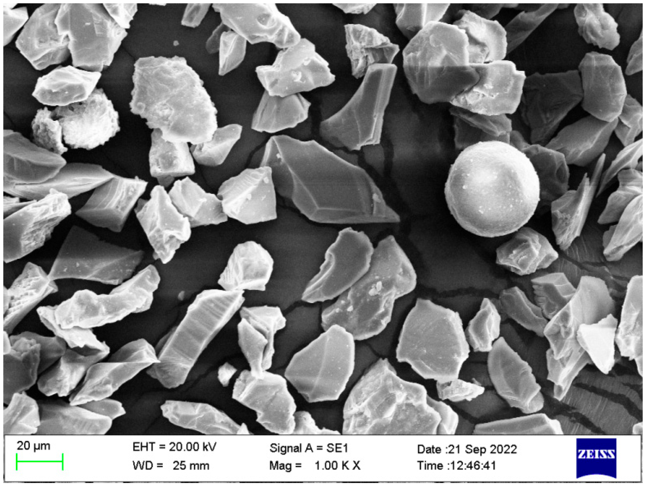
Q235 low carbon steel measuring 50 mm × 15 mm × 5 mm was used as the substrate. Before coating preparation, the substrate was degreased with acetone, air-dried, and sandblasted. In this study, the adhesive layer powder NiCr (80% Ni, 20% Cr) and the surface layer powder Al2O3 (Figure 1) were provided by Sanpuri New Materials Co., Ltd. (Beijing, China). The particle size of the binder layer powder NiCr and the top layer powder Al2O3 were both 15–45 μm. The ceramic precursor polymer sealing agent (YRS) (28.3 wt.% acrylic polysiloxane, 15.9 wt.% phenyl polysiloxane, 4.35 wt.% polysilicon diluent, and others) was produced by Anhui Yingrui Youcai Technology Co., LTD (Wuhu, China).

Figure 1.
SEM photo of Al2O3 powder.
2.2. Preparation of the Coating
The alumina coating was applied by a high-efficiency supersonic particle spraying system (HEP jet, State Key Laboratory of Remanufacturing, Beijing, China). The adhesive layer thickness was about 50 μm, and the alumina coating thickness was about 250 μm. The spraying parameters were optimized by the research group, as shown in Table 1.

Table 1.
Process parameters of supersonic plasma spraying.
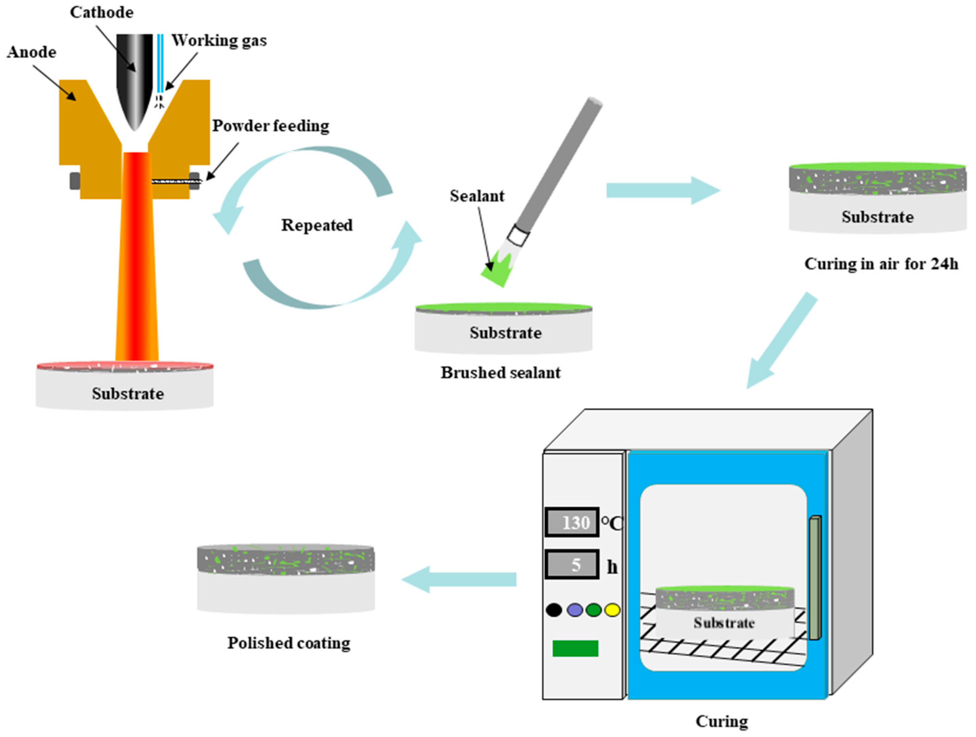
The three preparation schemes of the coatings are as follows: spray coating of Al2O3 powder several times to form a pure Al2O3 coating; traditional sealed coating where the applied coating was immersed in the sealing agent, and ultrasonic vibration was carried out at room temperature and pressure for 1 h. The sealing-treated coating was allowed to air-dry for 24 h, and then heat-treated at 130 °C for 5 h; (Figure 2) the alternating sealing coating process, as shown in Figure 2, used supersonic plasma spraying equipment to apply an alumina film of about 20 μm on the surface of the substrate, and then the YRS sealer was loaded into the atomization watering can and sprayed on the surface of the cooled alumina film, allowed to stand for 10 min to permit the impregnation of the sealer into the pores of the film and cross-linking of the liquid YRS sealer into a gel state. Then, the sample was preheated to 130 °C for the next spraying, and the prepared film was sprayed with the YRS sealer, and the process was repeated until the coating thickness reached 250 μm. Finally, the sealer was cured.
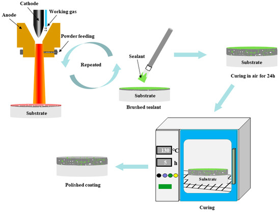
Figure 2.
Flow chart of the preparation of the alternating sealing coating.
2.3. Microscopic Topography Characterization
The coated substrates were examined and analyzed by SEM (Nova NanoSEM50, FEI, Hillsboro, OR, USA). The coating was characterized using an EDS, while the XRD (Bruker D8 Advance, Bruker, Ettlingen, Germany) with Cu target K α-ray was used in the scanning range of 10°–90°. The Cu target K α-ray was used to analyze the tested sample data using MDI Jade6.0 software (MDI, Los Angeles, CA, USA) to obtain the corresponding XRD map and phase information. Samples were subjected to XRD analysis after the removal of a 50 μm thick surface layer (50 μm thick layers).
2.4. Hardness Test
The VICS (HVS–1000A, Beijing Times Yinghai Technology Co., Ltd., Beijing, China) was used to test the coating cross-section. The samples were ground before the test, and then were loaded in the vertical direction to the coating. The main parameters of the sample were load 0.986 N, stress 0.1 kg, and retention time 10 s.
2.5. Corrosion Test
The corrosion resistance of the samples was characterized by electrochemical testing and immersion corrosion testing, and all samples were ground and polished to remove excess surface sealant before testing. The electrochemical corrosion behavior of the alternating sealing coating, traditional sealed coating, and spray coating was measured by an electrochemical workstation (P4000, Serqi Technology (Beijing) Co., Ltd., Beijing, China). A three-electrode system was used, with a platinum electrode as the auxiliary electrode (CE), a saturated calomel electrode (SCE) as the reference electrode (RE), and the coated sample as the working electrode (WE). The exposed area of all the working electrodes was 1 cm2. All corrosion media were 5 wt.% NaCl and the tests were performed at 25 ± 1 °C. The kinetic potential polarization curve was measured starting 1 h after sample immersion into the solution at a scan rate of 0.2 mV/s with a scan range of −1 V–1 V. The corrosion potential and the corrosion current density were fitted by Tafel extrapolation. The electrochemical impedance spectra of the coating were measured at an open circuit potential with measured frequency intervals of 105 Hz to 10−2 Hz with a signal amplitude of 10 mV. The measured data were fitted and interpreted by using ZView1.0 (ZEISS, Princeton, NJ, USA). To ensure the reproducibility of the experimental results, all experiments were tested in triplicate.
The full immersion corrosion test was done referring to JB/T 6073–92, using 5 wt.% NaCl as the corrosion medium. Before sample soaking, 704 silicone rubber (704 silicone rubber, Nanda, Anhui Yingrui Youcai Technology, Wuhu, China) was used to seal the matrix surface, to ensure that only the coating surface was exposed to the corrosion solution.
3. Results and Discussion
3.1. XRD Characterization
The XRD profiles of the powder, sealant, and the three coatings (spray coating, traditional sealed coating, and alternating sealing coating) are shown in Figure 3. Only the α-Al2O3 phase exists in the spraying feed, so the phase composition of the three coatings is similar, with a large amount of γ-Al2O3 and a trace amount of α-Al2O3. The α-phase transition to the defective spinel cubic metastable phase γ occurs during spraying. The γ-Al2O3 has a lower liquid-solid interface energy and prefers to nucleate from the molten state. The solidified cooling rate (about 106 K/s) is fast enough to prevent the phase transition [26] from γ to α. At the same time, a small amount of equilibrium α-Al2O3 also appears in the coating as the second phase, because the size and shape of the alumina feed are different, so the flight path cannot precisely control the particles in the jet. The particles at the edge of the jet cannot completely melt due to the lack of heat obtained and exist [27] in the coating in the form of unmelted Al2O3 particles. In addition, the XRD map of the sealing agent after curing only has a diffusion peak of amorphous SiO2, however, no obvious amorphous diffusion peak is found in the traditional sealed coating and alternating sealing coating, so the content of sealing agent in the coating is less.
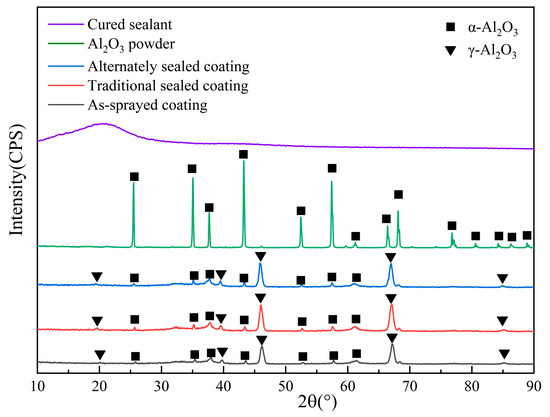
Figure 3.
XRD profiles of cured sealant, Al2O3 powder and three coatings.
3.2. Microstructure
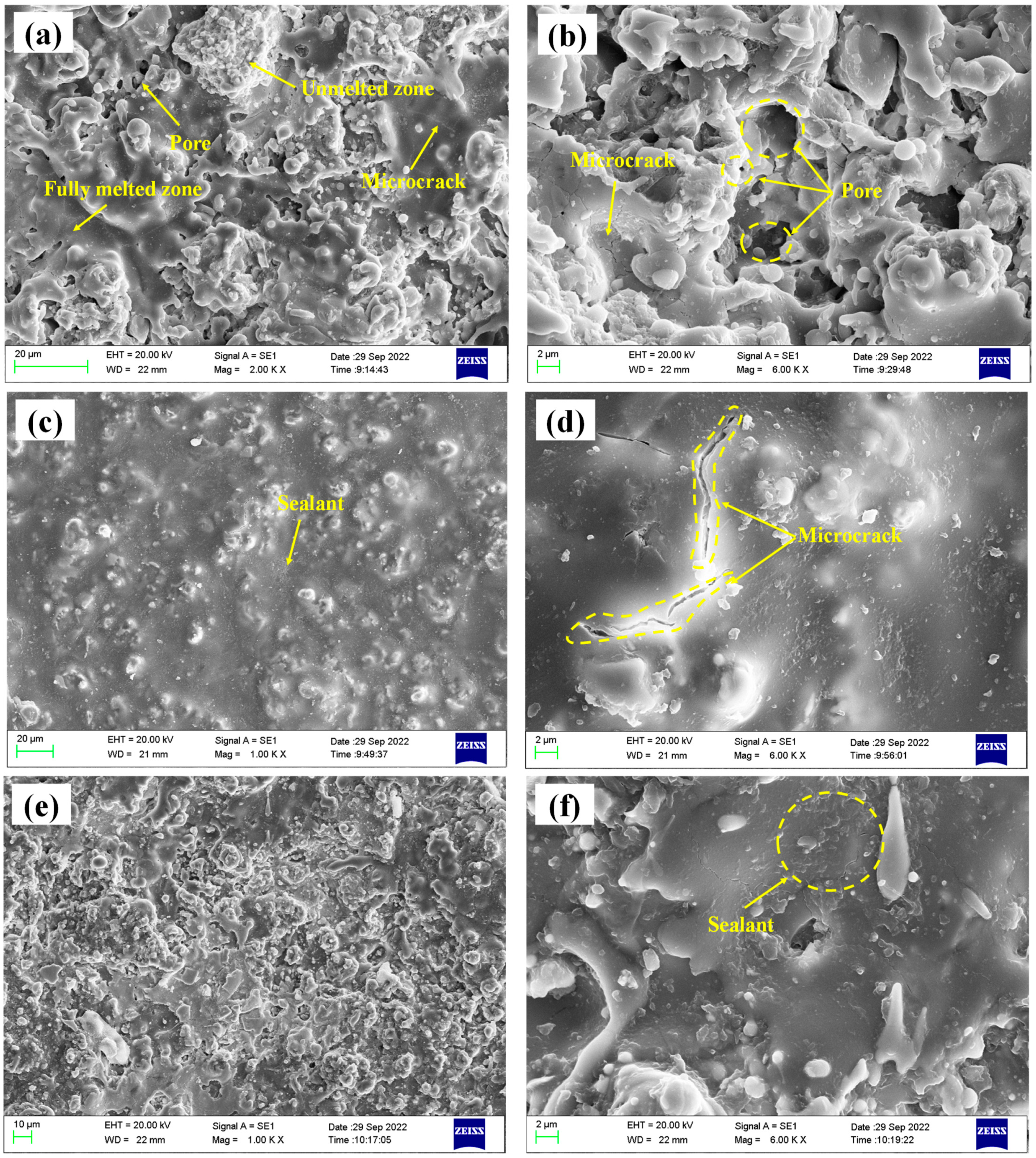
The surface micromorphology of the three coatings is shown in Figure 4. Figure 4a,b depicts the spray coating with a typical thermally sprayed ceramic coating structure. There are flat splats and unmolten or semi-molten particles. The pores formed by incomplete stacking on the surface and the microcracks formed by particle cooling shrinkage are seen. Figure 4c,d depicts the traditional sealed coating. There is a layer of sealing agent on the surface that completely covers the surface pores of the coating, but there are cracks formed by volume shrinkage of the sealing agent during the curing process. It is worth noting that the comprehensive performance of the sealing agent is poor, and the coating needs to be ground to remove the surface sealing layer before service. Figure 4e,f shows the alternating sealing coating. It can be seen that the pores on the coating surface have been sealed, but using the brush coating method, the sample surface adhesion is less.
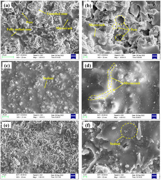
Figure 4.
Microtopography of the three coatings (a,b) spray coating; (c,d) traditional sealed coating; (e,f) alternating sealing coating.
The cross-sectional microstructures of the three coatings are shown in Figure 5. Comparing the cross-sectional map of the sprayed coating (Figure 5a), it is found that the sealant has filled the coating to a depth of about 125 μm (Figure 5b). As described in the literature [28], due to factors such as viscosity, wettability, pore characteristics, and trapped gas, it is difficult for the sealing agent to fully penetrate to the bottom of the coating, and it is easy to introduce defects in the sealing agent via the through holes of the coating due to volume curing and shrinkage (Figure 4d), which will affect the ability of the coating to block corrosive substances to a certain extent. As shown in Figure 5c, it is obvious that the overall structure of the alternating sealing coating is uniformly dense close to the dense area after the sealing coating. Only a few micropores exist and the sealing agent effectively fills the pores in each thin layer of hot spray Al2O3. The porosity of the cross sections of the three coatings was measured by image analysis, and the porosity of sprayed coating, traditional sealed coating, and alternating sealing coating were 2.4%, 1.39%, and 0.41%, respectively. Compared with the sprayed coating, the porosity of traditional sealed coating and alternating sealing coating decreased by 42.1% and 83%, respectively. Therefore, the alternating sealing method fills more pores than the traditional method, is not limited by the coating thickness, and reduces the probability of through-hole formation.
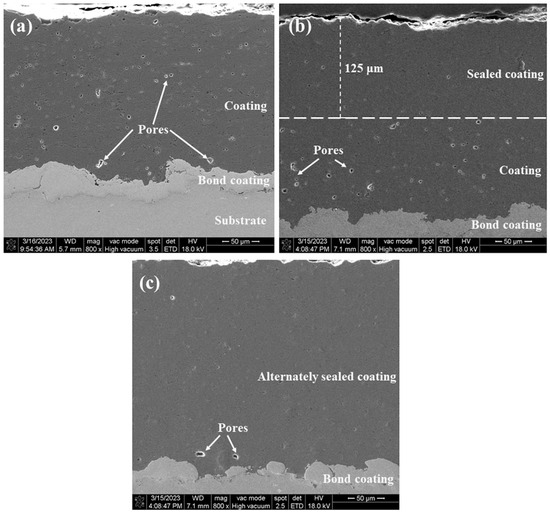
Figure 5.
Cross sectional microstructure of the three coatings (a) spray coating; (b) traditional sealed coating; (c) alternating sealing coating.
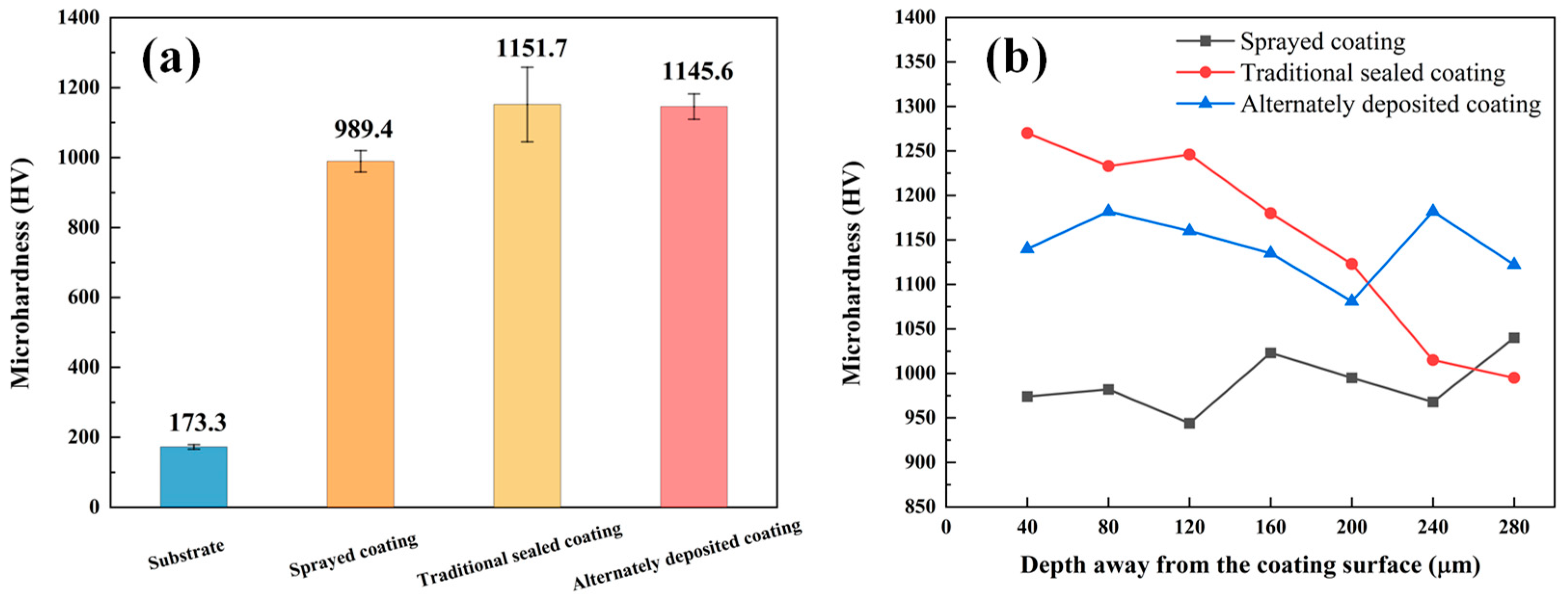
3.3. Microhardness
Figure 6a shows the average microhardness diagram of the three coatings. The hardness of the coating is much higher than the matrix. The sealing treatment can further improve the coating hardness, because the tightness of the coating helps the surrounding area to resist deformation, avoiding the Al2O3 load, and extending from the pore area to brittle fracture. Figure 6b shows the microhardness of the three coatings at different depths from the coating surface. It was found that the microhardness of the alternating deposition coating is evenly distributed, while the microhardness of the traditional sealed coating decreases with the increasing distance from the coating surface. According to the analysis, the sealant is evenly distributed in the alternating sealing coating, and the coating is dense, so the microhardness is significantly increased and evenly distributed. The microhardness of the traditional sealed coating is affected by the infiltration depth of the sealing agent. In addition, in the application process of alternating sealing coating, the hole sealing agent on the coating surface affects the deposition of molten particles to a certain extent, which affects the quality of the coating, and the surface hardness of the coating surface is slightly lower than that of the traditional sealed coating.
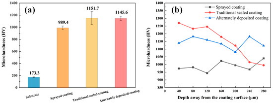
Figure 6.
Three coatings microhardness diagram: (a) average microhardness; (b) depth away from the coating surface.
3.4. Corrosion Behavior
3.4.1. Short-Term Electrochemical Tests
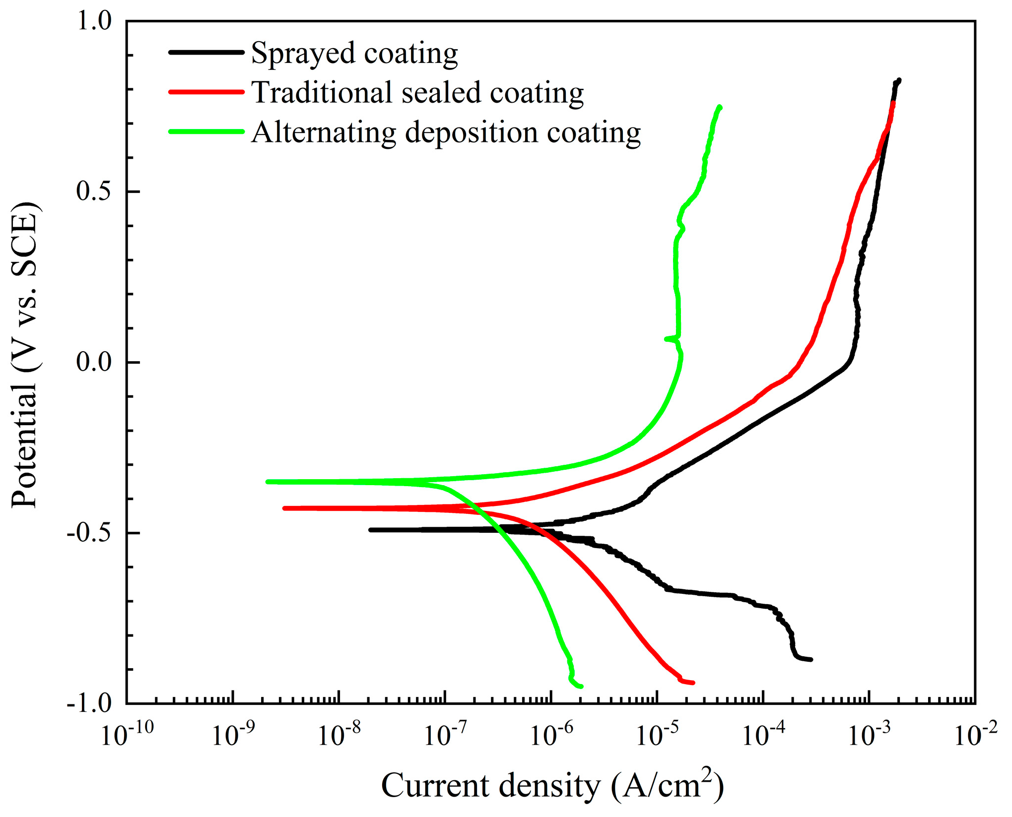
The potentiodynamic polarization curves of the three coatings in a 5 wt.% NaCl solution are shown in Figure 7. The corrosion parameters, such as corrosion current density (icorr), corrosion potential (Ecorr), and polarization resistance (Rp) calculated by the Tafel extrapolation method are shown in Table 2. The corrosion potential, as a thermodynamic concept, reflects the difficulty of corrosion. Under the same conditions, as the values of Ecorr become more negative, the greater the potential for corrosion to occur. The Ecorr of the alternating sealing coating (−424 mV) is more positive than the Ecorr of the traditional sealed coating (−350 mV). This shows that its corrosion tendency is smaller, and lower than spray coating (−490 mV). This behavior is related to the ability of the surface coating to act as a barrier to the corrosive medium. The corrosion current density is proportional to the corrosion rate and is very sensitive to the porosity of the protective coating. Table 2 shows that the icorr of the alternating sealing coating is 1.04 × 10⁻⁷ A/cm2, lower than the icorr of the traditional sealed coating (4.6019 × 10⁻⁷ A/cm2), and an order of magnitude lower than spray coating (1.8383 × 10⁻⁶ A/cm2).
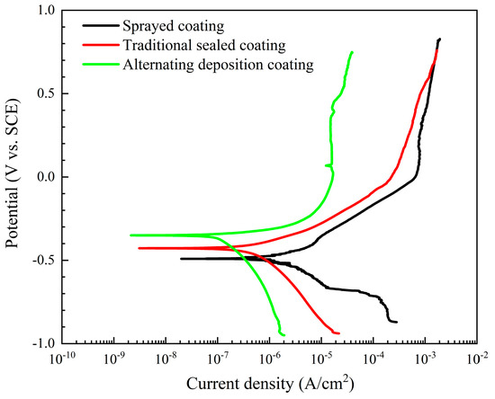
Figure 7.
Potentiodynamic polarization curves of three coatings in 5 wt.% NaCl solution.
Table 2.
Mean values of corrosion parameters obtained from potentiodynamic polarization measurements in triplicate for three coatings in 5 wt.% NaCl solution.
From the polarization test results, the protective efficiency, Si (%) of the films can be calculated by equal (1):
where ia and ib are the icorr of the sealed coating and the unsealed coating, respectively [15]. The calculation results are shown in Table 2. The sealing efficiency of the traditional sealing method for Al2O3 coating pores is 75% and the sealing efficiency of the alternating sealing method for Al2O3 coating pores is 95.6%. Therefore, these data show that sealing treatment can decrease porosity, resulting in enhanced corrosion resistance of Al2O3 coating. In addition, the alternating sealing method has a better effect than the traditional sealing method.
3.4.2. EIS Evaluation for Long-Time Immersion
The polarization curve data cannot predict the long-term corrosion resistance of the coating. Electrochemical impedance spectroscopy (EIS) has been widely used to measure and predict corrosion resistance and the life of protective coatings [29]. Therefore, EIS was performed on the three coatings under different exposure times in 5 wt.% NaCl solution and the variation of EIS characteristics with immersion time was studied. The Bode diagram of the three coatings with a thickness of about 300 μm is shown in Figure 8. Based on the typical EIS of the coating, we used the general equivalent circuit shown in Figure 9 to explain the EIS of the coatings. The capacitor is replaced by a constant phase element (CPE). Figure 9a shows the model of an equivalent circuit, which consists of the resistance of the solution (Rs), the capacitance of the coating (CPE-c), and the resistance of the coating (Rc). Among all the fitting results, only the 1 h result of the 120 μm alternating sealing coating comes from the model. In Figure 9b, Rs is used to represent the resistance of the solution, Rp and CPE-c are used to represent the pore resistance and coating capacitance, which represent the dielectric properties of the coating, and Rt and CPE-d are used to represent the linear polarization resistance and electric double layer capacitance, which describe the charge transfer process on the surface between the solution and the substrate. EIS is mainly used to describe the depth of electrolyte penetration into the coating, and the middle and late process of electrochemical corrosion at the interface of the substrate.
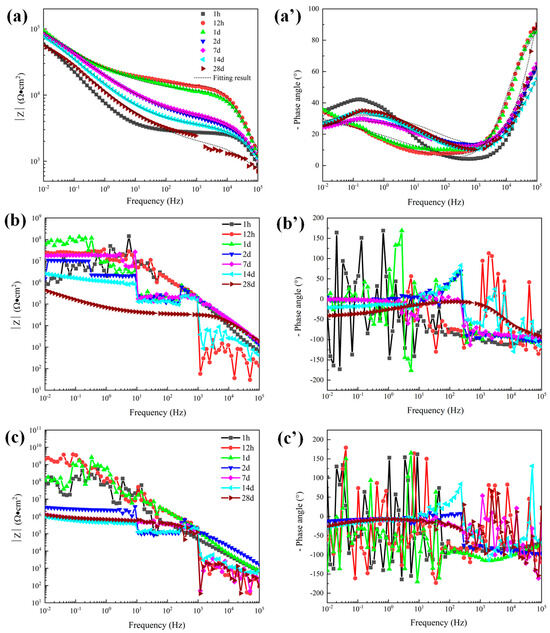
Figure 8.
Bode plots of 300 μm depths of three coatings in 5 wt.% NaCl solution. (a) |Z| of sprayed coating (a′) Phase angle of sprayed coating, (b) |Z| of traditional sealed coating, (b′) Phase angle of traditional sealed coating, (c) |Z| of alternating sealing coating (c′) Phase angle of alternating sealing coating.

Figure 9.
General model of an equivalent circuit proposed to carry out curve fitting for the EIS data from the coating systems exposed to 5 wt.% NaCl solution. (a) Early corrosion (b) Later corrosion.
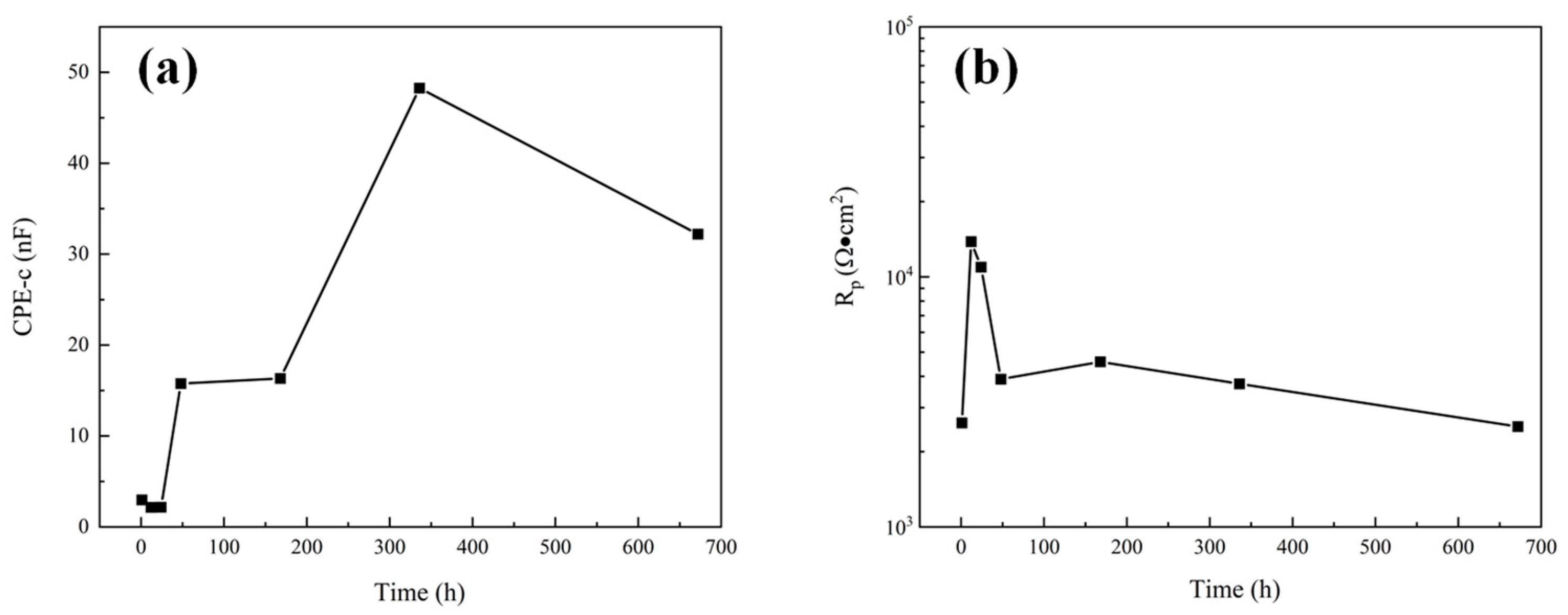
The dissolution of Al2O3 into a NaCl solution is extremely slow. Therefore, in the corrosion process of the Al2O3 coating system, the corrosion medium mainly penetrates the coating through the open pore defects and galvanic corrosion occurs at the interface of the substrate, resulting in the rapid dissolution of the steel substrate. For unsealed coatings (8a, a’), after 1 h immersion the second time constant appeared in the low frequency range, indicating that the corrosive medium has penetrated the coating and caused electrochemical corrosion at the substrate interface. Impedance at low frequency is related to corrosion at the substrate/solution interface. The phase angle of the sprayed coating decreased rapidly after 1 d, indicating that the corrosion rate of the sprayed coating increased. While impedance at high frequency represents the performance of the coating in the corrosion solution, the high frequency-impedance value increases first and then decreases with the increase of immersion time. The fitting results of pore resistance (Rp) and coating capacitance (CPE-c) can explain the corrosion process clearly [25]. The element value of Rp represents the protective ability of coatings, and CPE-c represented the diffusion speed of electrolytes. It can be seen from Figure 10 that Rp increased and CPE-c decreased slightly during 1 d immersion, the initially less corrosive medium is not enough to make the substrate interface dissolve quickly, so the corrosion product cannot accumulate at the substrate interface, and corrosion products diffuse to the surface of the coating through the open pore. The accumulation of corrosion products in the corrosion channel leads to a decrease in the diffusion rate of the electrolytes and the enhancement of the protection ability of the coating. With the diffusion of corrosion products into the solution, the protective ability of the coating gradually decreased, and the corrosion process tended to be stable.

Figure 10.
The variation of electrochemical corrosion parameters of sprayed coatings: (a) CPE-c; (b) Rp.
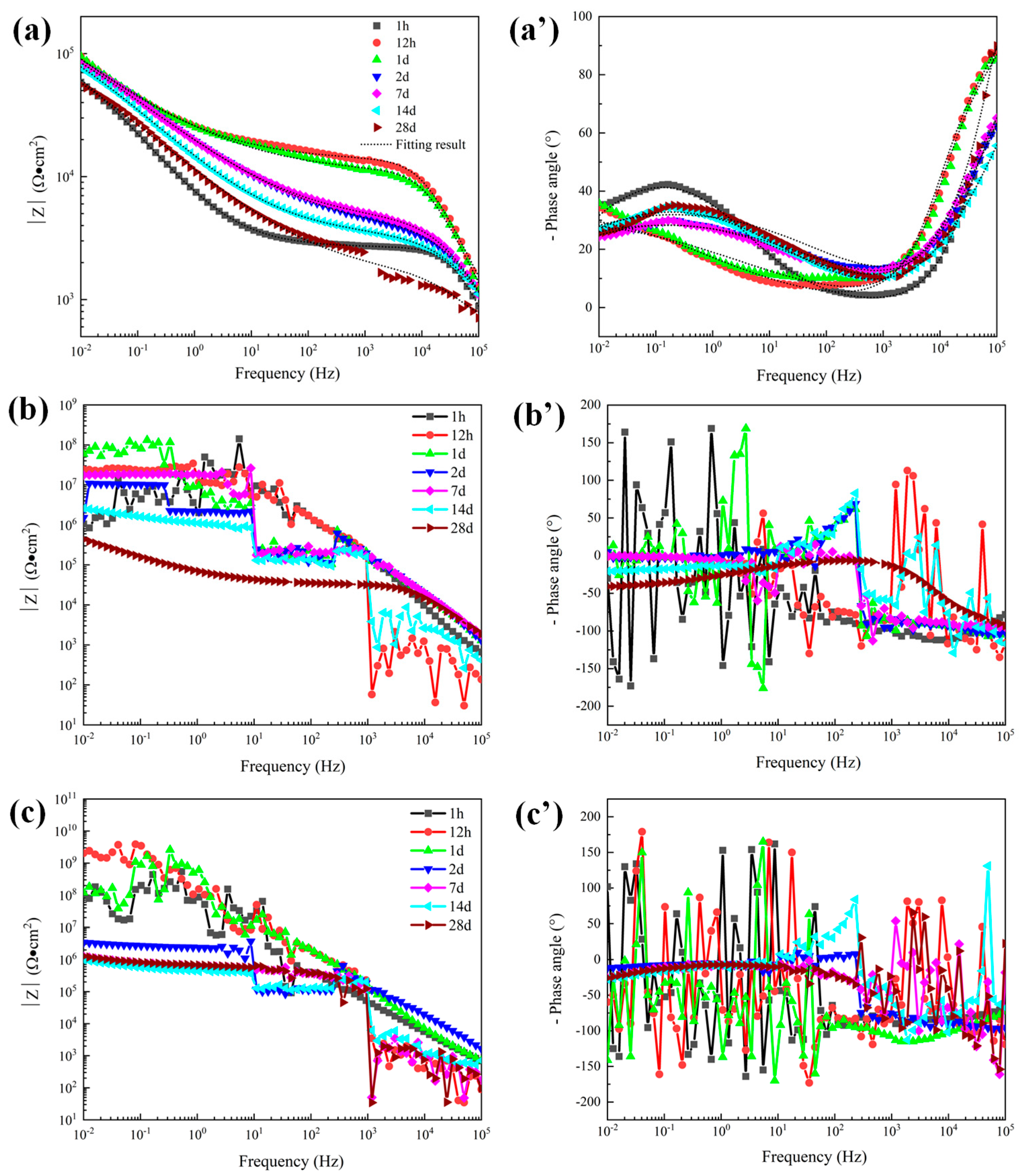
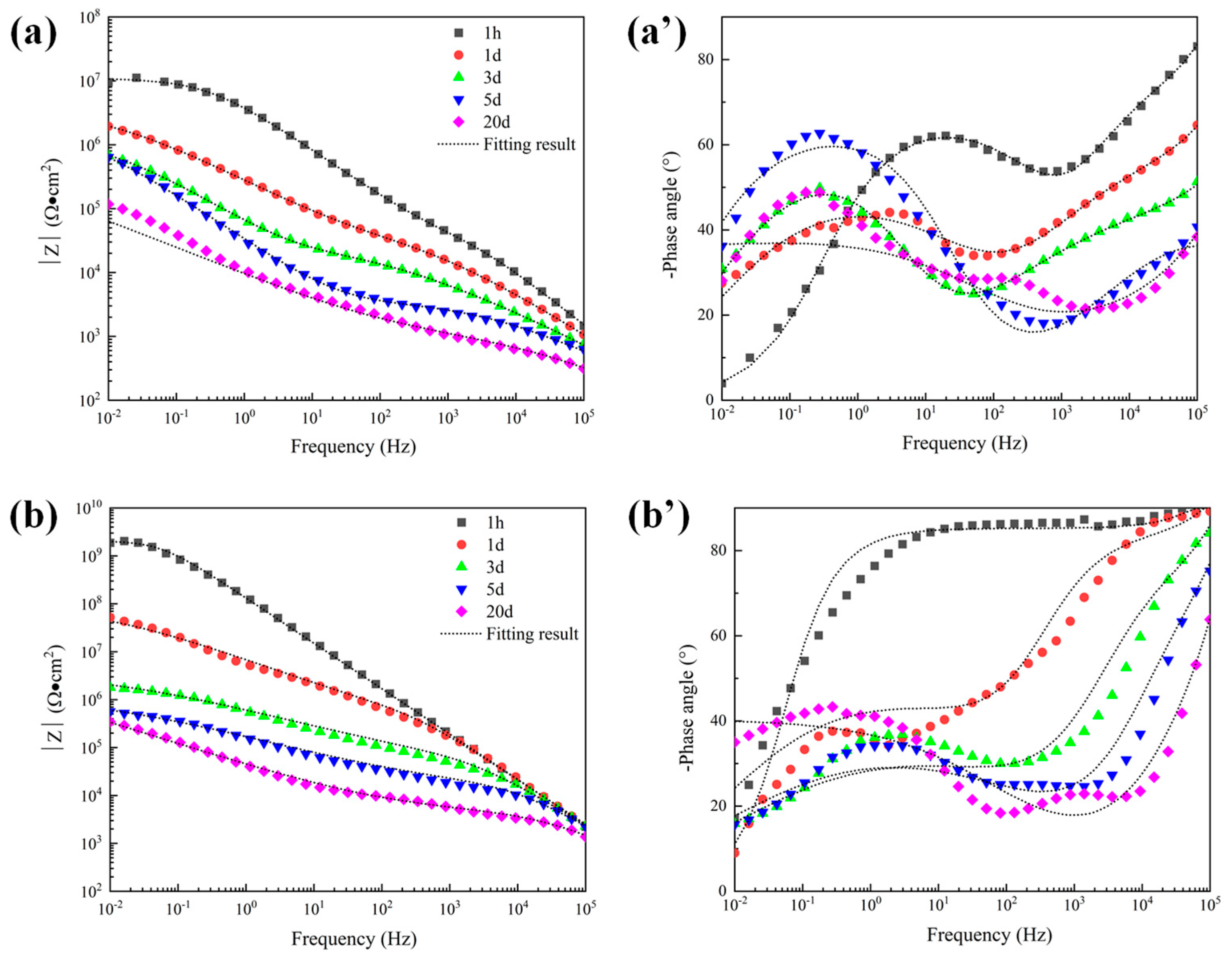
The Bode plots of the 300 μm alternating sealing coating and the traditional sealed coating in 5 wt.% NaCl solution are shown in Figure 8. EIS data are nonlinear data because the coating is a high impedance system, which exceeds the upper limit of detection of the electrochemical workstation. Further increasing the disturbance voltage to 50 mV has no obvious effect. The traditional sealed coating shown in Figure 8b,b’ shows linear reliable impedance data after immersion for 28 days. It shows that electrochemical corrosion occurs in the coating system at this time. However, there is no linear and effective electrochemical corrosion data for the alternating sealing coating during the whole immersion period. To a certain extent, it is proved that the alternating sealing coating has better ability to act as a barrier to corrosive media.
The open porosity of the coating is sensitive to the thickness of the coating, being inversely proportional to the coating thickness [9]. Therefore, to further explore the electrochemical corrosion behavior of the alternating sealing coating and traditional sealed coating, the EIS of coatings with a thickness of 120 μm was measured. The Bode plots of the traditional sealed coating and the alternating sealing coating are shown in Figure 11. As seen in Figure 11b’, the phase angle of the alternating sealing coating after immersion for 1 h does not show a new capacitance response at low frequency and there is only one time constant, indicating that the coating at this stage can prevent the corrosion medium from infiltrating into the substrate interface, thus the coating can effectively protect the steel substrate from corrosion. The second capacitance response at low frequency can be seen after 12 h immersion and there are two time constants, indicating that the corrosive medium penetrates the alternating sealing coating after 12 h and has penetrated the steel substrate interface. In Figure 11a’, the traditional sealed coating has a double capacitance response throughout the immersion cycle, indicating that the corrosive medium has penetrated the substrate interface within 1 h. It can be seen from Figure 11b that the high-frequency impedance of the alternating sealing coating is stable, indicating that the alternating sealing coating may only have a very small number of small and tortuous channels, and the diffusion of corrosion medium and corrosion products are impeded, so it still maintains good protective performance. In Figure 11a, the impedance modulus of the traditional sealed coating decreases with increasing immersion time of the coating in the whole frequency range, indicating that the traditional sealed coating may have more structural defects and gradually become a complete corrosion channel during the immersion process. Thus, the impedance modulus of the alternating sealing coating is higher than that of the traditional sealed coating in the whole frequency range at the same immersion time.
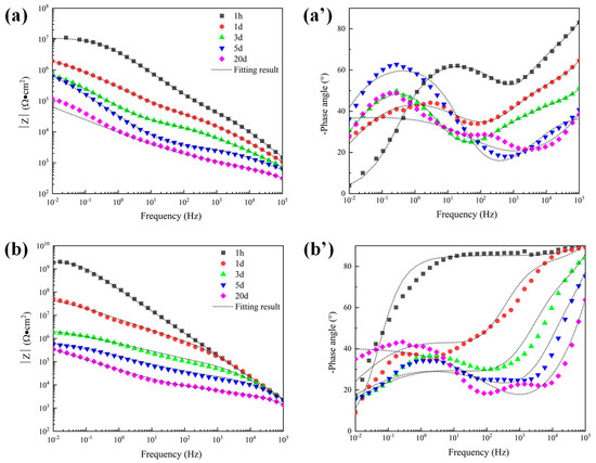
Figure 11.
Bode plots of 120 μm depths of coatings in 5 wt.% NaCl solution. (a) |Z| of traditional sealed coating, (a′) Phase angle of traditional sealed coating, (b) |Z| of alternating sealing coating (b′) Phase angle of alternating sealing coating.
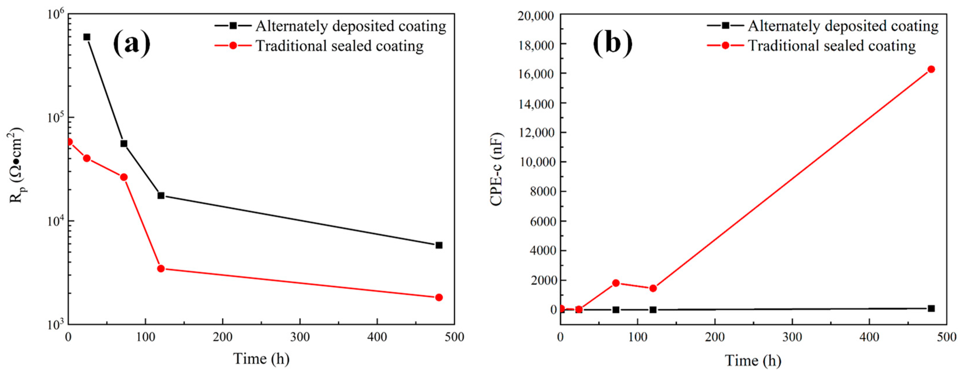
The impedance data of alternating sealing coating for 1 h were fitted in Figure 9a, and the remaining impedance data are fitted by the equivalent circuit shown in Figure 9b. The fitting results of Rp and CPE-c are shown in Figure 12. It can be seen that the Rp of the alternating sealing coating and the traditional sealed coating has the same trend, and Rp gradually decreases with the increase of immersion time. However, the Rp of the alternating sealing coating is much larger than that of the traditional sealed coating, and the pore resistance of the coating after immersion for 20 d is 5815 Ω·cm2, which is about 3.2 times that of the traditional sealed coating. In Figure 12b, the CPE-c of the traditional sealed coating rises rapidly, indicating that the electrolytes penetrate the coating quickly, while the alternating sealing coating CPE-c is relatively flat, so the electrolytes penetrate the coating slowly. Therefore, the alternating sealing coating has lower porosity and higher protective performance, and the alternating sealed method has better-closed pores.

Figure 12.
The variation of electrochemical corrosion parameters of alternating sealing coating and traditional sealed coating: (a) Rp; (b) CPE-c.
3.4.3. Immersion Corrosion Test
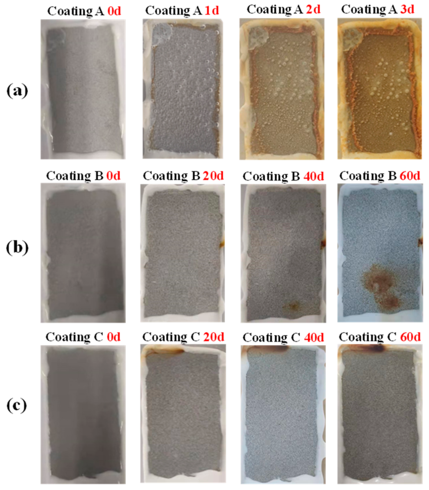
Figure 13 shows representative photos of immersion corrosion of three coatings with a thickness of 120 μm in 5 wt.% NaCl solution. The A coating is the sprayed coating, and it can be seen that in immersion 1 d, red rust spots have appeared on the coating, and the corrosion resistance of the sprayed coating is extremely poor. The B coating is the traditional sealed coating. After immersion for 40 d, there are obvious small pieces of rust on the surface. The analysis shows that the traditional sealed coating has a stable corrosion channel at this time and the corrosion products are concentrated at the channel mouth. A large piece of rust appeared at 60 d, indicating the acceleration of corrosion. The C coating is the alternating sealing coating, which shows good corrosion resistance. Under 120 μm thickness, there is no obvious accumulation of corrosion products on the surface even after immersion for 60 d, but there is rust on the top of the coating caused by the corrosion medium penetrating the silicone rubber, directly corroding the steel substrate. Combined with EIS, it can be seen that there will still be some open pores in the alternating sealing coating when the coating is thinner. However, due to the chemical stability of Al2O3 and sealant, micro-defects cannot be extended to large-sized corrosion channels and due to the blockage of corrosion products, the corrosion process is extremely slow, so there is no obvious accumulation of corrosion products on the surface of the alternating sealing coating.
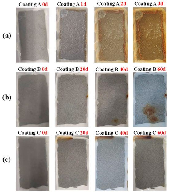
Figure 13.
Photos of immersion corrosion of three coatings in 5 wt.% NaCl solution. (a) Sprayed coating, (b) Traditional sealed coating and (c) Alternating sealing coating.
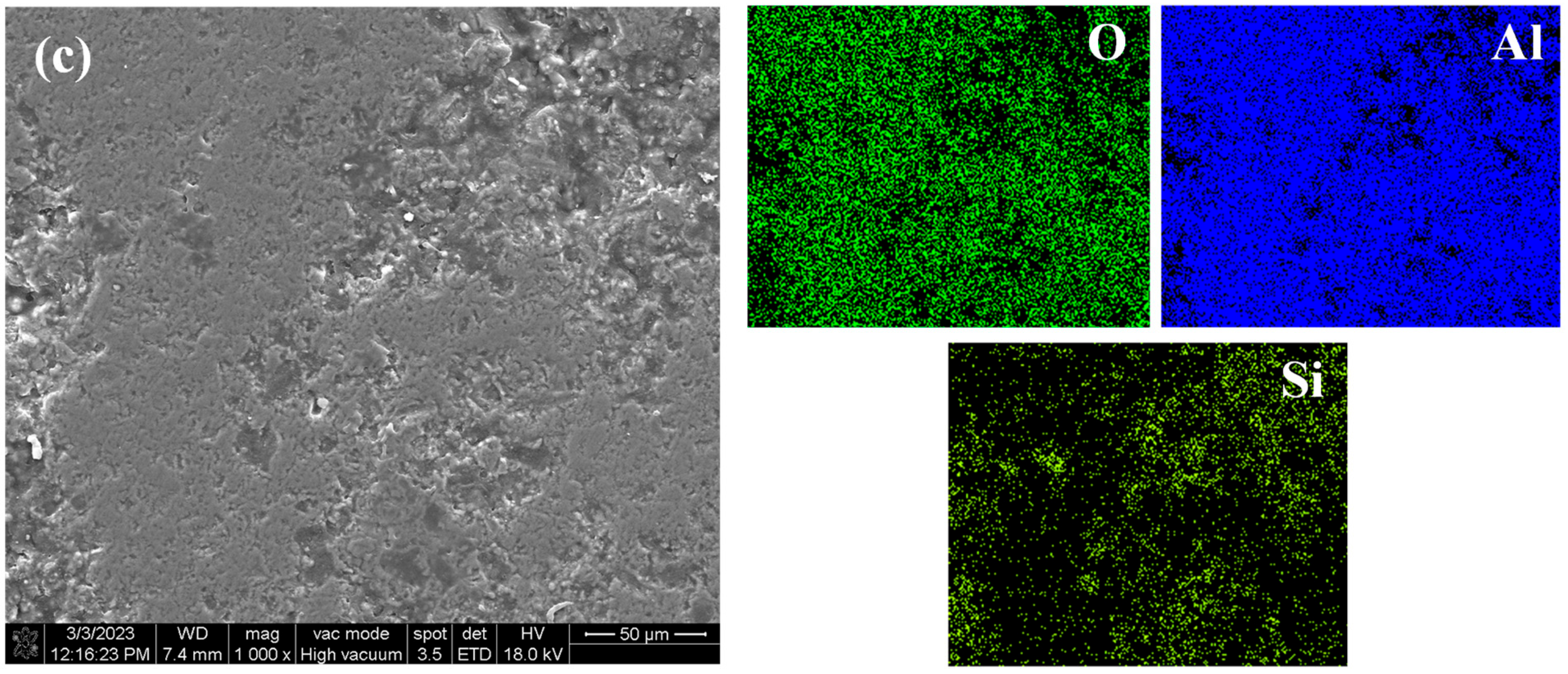
Figure 14a shows the surface morphology and element distribution of the sprayed coating after immersion corrosion for 3 d in 5 wt.% NaCl solution. Corrosion is seen due to the large number of pores and unmelted and semi-melted particles in the Al2O3 coating. Therefore, even in a short time of immersion, a large number of corrosion products can be seen on the surface, forming a loose corrosion product film, indicating that it has poor barrier ability to the corrosive medium and cannot provide long-term effective protection for the substrate. Figure 14b shows the surface morphology and element distribution of the traditional sealed coating after immersion for 60 d in 5 wt.% NaCl solution. Some loose corrosion products can be seen on the surface, because the sealant will produce some microcracks due to curing shrinkage and solvent volatilization. Along the microcracks and solvent volatilization channels, small-sized Cl− and H2O can still slowly penetrate the sealing layer, resulting in corrosion of the substrate [30]. Figure 14c shows the surface morphology and element distribution of the alternating sealing coating after immersion for 60 d in 5 wt.% NaCl solution. It can be seen that there is no obvious corrosion product or Fe element distribution on the surface. The immersion results are consistent with EIS results, indicating that the alternating sealing method has higher sealing efficiency and can greatly improve the coating life.
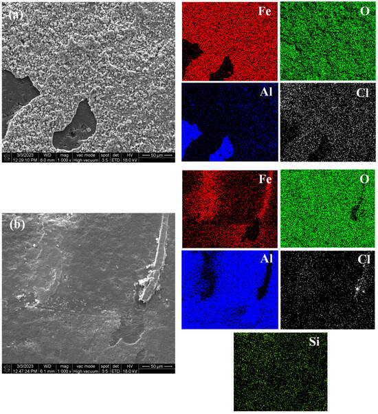
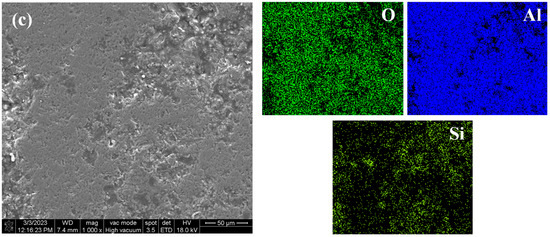
Figure 14.
The surface morphology and element distribution of the three coatings after immersion. (a) Sprayed coating (b) Traditional sealed coating and (c) Alternating sealing coating.
3.5. Effect of Sealing Treatment on Corrosion
Defects are inevitable in thermally sprayed Al2O3 coatings. In general, in the long-term corrosion process, the pores can be interconnected to form a channel between the corrosion environment and the substrate, and the coating equilibrium potential is often higher than the substrate material, resulting in galvanic corrosion at the interface of the substrate, resulting in the dissolution of the substrate material [31]. In addition, during the long-term corrosion process, the pore walls in the coating will slowly dissolve, causing closed pores to connect or directly connect with the open pores to expand the corrosion channel [9]. The unsealed coating has two time constants after immersion for 1 h, indicating that the corrosive medium has infiltrated the substrate interface, and the continuous dissolution of the steel substrate eventually leads to the failure of the coating.
The EIS and immersion results show that sealing treatment can further improve the corrosion resistance of the coating. During the sealing process, the liquid sealant can infiltrate into the open pores of the coating through capillary action, and then cross-linked and solidified into a dense structure by heat treatment to fill the pores of the coating. Filling the pores of the coating by the sealant limits the channel through which the corrosive medium attacks the substrate and improves the protection ability of the substrate. From the EIS and immersion results, the alternating sealing coating has better corrosion resistance than the traditional sealed coating.
For the traditional sealing technology, the structural defects are filled by the infiltration of the sealant into the open pores of the coating. During the sealing process, the sealant enters the pore through wettability, but infiltration is affected by the reaction force generated by the air and water in the pores and cracks, and cannot reach the bottom of the open pores. At the same time, it is difficult to fill small cracks and pores due to the limitation of the viscosity of the sealant. In addition, during the curing process of the sealant, gas is released and the volume will shrink, causing cracks, which limit the sealing effect [32,33]. Therefore, small open pores inside the coating remain, which have a good protective effect in the early stage of corrosion. During long-term service, the corrosive medium will still penetrate the coating slowly, resulting in coating failure. For the alternating sealing technology, sealing each thermally sprayed thin layer can close more pores and cracks. At the same time, the small cracks that cannot be filled and the small cracks formed by pores and curing shrinkage tend to be closed in the deposition of subsequent particles. For the alternating sealing coating, defects are difficult to connect as closed pores have little effect on the corrosion resistance of the coating. In addition, the thickness of the dense layer of the alternating sealing coating is not limited by the infiltration of the sealant, and the corresponding thickness of the protective coating can be prepared according to the actual service requirements. The long-term corrosion results show that the alternating sealing coating has the best long-term corrosion resistance. It is worth noting that from the EIS experimental results, the thicker the coating is, the smaller the probability of pore connectivity is. For components that are expected to serve in a corrosive environment for a long time, the surface thermal spraying protective coating should be as thick as possible.
The selection of sealing technology should be based on practical application. Although the alternating sealing coating exhibits better performance in a long-term corrosive environment, the preparation process is cumbersome, has low deposition efficiency, and has high cost. The traditional sealed coating process is simple, low cost, and in the early stage of corrosion, has good corrosion resistance, which is suitable for a short-term corrosion resistance environment.
4. Conclusions
The Al2O3 coating was sealed by traditional sealing technology and alternating sealing technology, and the sealing effect was evaluated by microstructure and corrosion behavior. The following are some conclusions:
- Both traditional sealing technology and alternating sealing technology permit YRS sealant to penetrate coating defects and fill pores. The penetration depth of the traditional sealed coating is about 125 μm, but the alternating sealing technology can prepare a dense Al2O3 coating to the required thickness.
- The two-dimensional porosities of spray coating, traditional sealed coating and alternating sealing coating are 2.4%, 1.39% and, 0.41%, respectively. The results of polarization curves show that the corrosion potential of the alternating sealing coating is 74 mV higher than that of the traditional sealed coating, and the corrosion current density is reduced by about 78%. The alternating sealing technology can close pores better and effectively improves the corrosion resistance of the coating.
- The microhardness of spray coating, traditional sealing coating, and alternating sealing coating are 989.4 HV0.1, 1151.7 HV0.1 and 1145.6 HV0.1, respectively, and their microhardness is greater than that of the matrix. With the increase of coating thickness, the microhardness of the traditional sealing coating will continue to decrease, while the microhardness of the alternating sealing coating will be evenly distributed.
- After 20 days of immersion in a 5 wt.% NaCl solution, the Rp of the alternating deposited coating was 5815 Ω·cm2, which is approximately 3.2 times higher than that of the conventional hole-sealing coating. In the full immersion corrosion test, corrosion products appeared on the surface of the conventional sealing coating after 40 days, while there were no apparent corrosion products on the surface of the alternating deposited coating after 60 days of immersion.
- Based on the EIS and immersion corrosion analysis, it can be concluded that the alternating sealing technology is effective in preventing the formation of connectivity pores. Additionally, it has a better hindering effect on the inward diffusion of corrosive media compared to traditional sealing coatings. Furthermore, increasing the thickness of the sealing layer improves the corrosion resistance beyond that of traditional sealing technology.
Author Contributions
Conceptualization, M.L.; methodology, M.L., L.J. and H.W. (Haozhen Wang); analysis, Y.B.; Investigation, Y.B.; data acquisition, G.M. and X.Z.; writing—original draft, Y.F.; supervision, G.M. and X.Z.; project administration, H.W. (Haidou Wang); funding acquisition, L.J. All authors have read and agreed to the published version of the manuscript.
Funding
This work was supported by the National Natural Science Foundation of China (Grant No. 52130509 and 52075542), and 145 Project.
Institutional Review Board Statement
Not applicable.
Informed Consent Statement
Not applicable.
Data Availability Statement
Data are contained within the article.
Acknowledgments
Authors would like to thank Beijing Sanspuri New Materials Co., Ltd. (China) for providing high-quality Al2O3 powders.
Conflicts of Interest
The authors declare no conflicts of interest.
References
- Peng, Q.-Q.; Liu, M.; Huang, Y.-F.; Ma, G.-Z.; Guo, W.-L.; Wang, H.-D.; Xing, Z.-G. Development mechanism and performance of Al2O3-PF composite coating on epoxy resin matrix composite surface by supersonic plasma spraying. Surf. Coat. Technol. 2022, 446, 128762. [Google Scholar] [CrossRef]
- Gan, J.A.; Berndt, C.C. Quantification and Taxonomy of Pores in Thermal Spray Coatings by Image Analysis and Stereology Approach. Metall. Mater. Trans. A Phys. Metall. Mater. Sci. 2013, 44, 4844–4858. [Google Scholar] [CrossRef]
- Qiao, X.; Wang, Y.M.; Weng, W.X.; Liu, B.L.; Li, Q. Influence of pores on mechanical properties of plasma sprayed coatings: Case study of YSZ thermal barrier coatings. Ceram. Int. 2018, 44, 21564–21577. [Google Scholar] [CrossRef]
- Thirumalaikumarasamy, D.; Balasubramanian, V.; Sree Sabari, S. Prediction and optimization of process variables to maximize the Young’s modulus of plasma sprayed alumina coatings on AZ31B magnesium alloy. J. Magnes. Alloys 2017, 5, 133–145. [Google Scholar] [CrossRef]
- Sun, F.; Fan, X.; Zhang, T.; Jiang, P.; Yang, J. Numerical analysis of the influence of pore microstructure on thermal conductivity and Young’s modulus of thermal barrier coating. Ceram. Int. 2020, 46, 24326–24332. [Google Scholar] [CrossRef]
- Chen, N.; Song, X.; Liu, Z.; Lin, C.; Zeng, Y.; Huang, L.; Zheng, X. Quantitative Analysis of the Relationship Between Microstructures and Thermal Conductivity for YSZ Coatings. J. Therm. Spray Technol. 2017, 26, 745–754. [Google Scholar] [CrossRef]
- Munagala, V.N.V.; Bessette, S.; Gauvin, R.; Chromik, R.R. Sliding wear of cold sprayed Ti6Al4V coatings: Effect of porosity and normal load. Wear 2020, 450–451, 203268. [Google Scholar] [CrossRef]
- El-Sayed, M.M. Thermal shock behaviour of alumina-iron composites. J. Mater. Sci. Technol. 2009, 18, 347–350. [Google Scholar]
- Zhang, S.D.; Zhang, W.L.; Wang, S.G.; Gu, X.J.; Wang, J.Q. Characterisation of three-dimensional porosity in an Fe-based amorphous coating and its correlation with corrosion behaviour. Corros. Sci. 2015, 93, 211–221. [Google Scholar] [CrossRef]
- Zhang, S.D.; Wu, J.; Qi, W.B.; Wang, J.Q. Effect of porosity defects on the long-term corrosion behaviour of Fe-based amorphous alloy coated mild steel. Corros. Sci. 2016, 110, 57–70. [Google Scholar] [CrossRef]
- Petrovskiy, P.; Sova, A.; Doubenskaia, M.; Smurov, I. Influence of hot isostatic pressing on structure and properties of titanium cold-spray deposits. Int. J. Adv. Manuf. Technol. 2019, 102, 819–827. [Google Scholar] [CrossRef]
- Petrovskiy, P.; Travyanov, A.; Cheverikin, V.V.; Chereshneva, A.A.; Sova, A.; Smurov, I. Effect of encapsulated hot isostatic pressing on properties of Ti6Al4V deposits produced by cold spray. Int. J. Adv. Manuf. Technol. 2020, 107, 437–449. [Google Scholar] [CrossRef]
- Yang, K.; Li, J.; Wang, Q.; Li, Z.; Jiang, Y.; Bao, Y. Effect of laser remelting on microstructure and wear resistance of plasma sprayed Al2O3-40%TiO2 coating. Wear 2019, 426–427, 314–318. [Google Scholar] [CrossRef]
- Liu, Q.; Dong, T.; Fu, B.; Li, G.L.; Yang, L.J. Effect of Laser Remelting on Microstructure and Properties of AlCoCrFeNi High-Entropy Alloy Coating. J. Mater. Eng. Perform. 2021, 30, 5728–5735. [Google Scholar] [CrossRef]
- Tian, J.; Wei, Y.; Li, C.; Yang, G.J.; Li, C.J. Effect of Post-spray Shot Peening Treatment on the Corrosion Behavior of NiCr-Mo Coating by Plasma Spraying of the Shell–Core–Structured Powders. J. Therm. Spray Technol. 2017, 27, 232–242. [Google Scholar] [CrossRef]
- Liu, Z.; Yan, D.; Dong, Y.; Yang, Y.; Chu, Z.; Zhang, Z. The effect of modified epoxy sealing on the electrochemical corrosion behaviour of reactive plasma-sprayed TiN coatings. Corros. Sci. 2013, 75, 220–227. [Google Scholar] [CrossRef]
- Zhang, J.; Wang, Z.; Lin, P.; Lu, W.; Zhou, Z.; Jiang, S. Effect of Sealing Treatment on Corrosion Resistance of Plasma-Sprayed NiCrAl/Cr2O3-8wt.%TiO2 Coating. J. Therm. Spray Technol. 2010, 20, 508–513. [Google Scholar] [CrossRef]
- Thi, H.P.; Van, T.N.; Nguyen, T.A.; Le Thu, Q.; Thi, L.P.; Bich, T.D.; Van, T.T.; Quoc, C.L. Cr3C2-25NiCr Cermet Coating: Preparation, PTFE Sealant, Wear and Corrosion Resistances. J. Therm. Spray Technol. 2021, 30, 716–724. [Google Scholar] [CrossRef]
- Singh, H.; Chatha, S.S.; Sidhu, H.S. Influence of Heat Treatment and Sealing on Hot Corrosion Behavior of 80Ni-20Cr Coatings. J. Therm. Spray Technol. 2019, 28, 1478–1491. [Google Scholar] [CrossRef]
- Wang, Q.; Ramachandran, C.S.; Smith, G.M.; Sampath, S. Sliding wear behavior of air plasma sprayed Al2O3 coatings sealed with aluminum phosphate. Tribol. Int. 2017, 116, 431–439. [Google Scholar] [CrossRef]
- Zhang, J.; Wang, Z.; Lin, P. Effects of sealing on corrosion behaviour of plasma-sprayed Cr2O3-8TiO2coating. Surf. Eng. 2013, 29, 594–599. [Google Scholar] [CrossRef]
- Shao, F.; Yang, K.; Zhao, H.; Liu, C.; Wang, L.; Tao, S. Effects of inorganic sealant and brief heat treatments on corrosion behavior of plasma sprayed Cr2O3-Al2O3 composite ceramic coatings. Surf. Coat. Technol. 2015, 276, 8–15. [Google Scholar] [CrossRef]
- Amousoltani, N.; Salimijazi, H.; Golozar, M. Study of alumina sealing of HVOF thermally sprayed WC-Co coatings by sol-gel method. Mater. Res. Express 2019, 7, 16410. [Google Scholar] [CrossRef]
- Zhang, L.M.; Zhang, S.D.; Ma, A.L.; Hu, H.X.; Zheng, Y.G.; Yang, B.J.; Wang, J.Q. Influence of sealing treatment on the corrosion behavior of HVAF sprayed Al-based amorphous/nanocrystalline coating. Surf. Coat. Technol. 2018, 353, 263–273. [Google Scholar] [CrossRef]
- Wang, Y.; Jiang, S.L.; Zheng, Y.G.; Ke, W.; Sun, W.H.; Wang, J.Q. Effect of porosity sealing treatments on the corrosion resistance of high-velocity oxy-fuel (HVOF)-sprayed Fe-based amorphous metallic coatings. Surf. Coat. Technol. 2011, 206, 1307–1318. [Google Scholar] [CrossRef]
- Wang, C.; Fan, L.; Fan, J.; Zhang, D.; Wang, H. Effect of spraying power on microstructure and properties of supersonic plasma sprayed Al2O3 coating on porous Si3N4 substrate. J. Alloys Compd. 2013, 559, 152–157. [Google Scholar] [CrossRef]
- Matthews, S.; Taliana, F.; James, B. Heat treatment of plasma-sprayed Al2O3 and Al2O3-WO3 coatings between 500 and 1000 °C. Surf. Coat. Technol. 2012, 212, 109–118. [Google Scholar] [CrossRef]
- Knuuttila, J.; Sorsa, P.; Mäntylä, T. Sealing of thermal spray coatings by impregnation. J. Therm. Spray Technol. 1999, 8, 249–257. [Google Scholar] [CrossRef]
- Lee, H.; Singh, J.K. Influence of calcium nitrate on morphology and corrosion characteristics of ammonium phosphate treated Aluminum coating deposited by arc thermal spraying process. Corros. Sci. 2019, 146, 254–268. [Google Scholar] [CrossRef]
- Erdogan, C.; Swain, G. Conceptual sacrificial anode cathodic protection design for offshore wind monopiles. Ocean Eng. 2021, 235, 109339. [Google Scholar] [CrossRef]
- Zeng, Z.; Sakoda, N.; Tajiri, T.; Kuroda, S. Structure and corrosion behavior of 316L stainless steel coatings formed by HVAF spraying with and without sealing. Surf. Coat. Technol. 2008, 203, 284–290. [Google Scholar] [CrossRef]
- Liu, M.M.; Hu, H.X.; Zheng, Y.G. Effects of three sealing methods of aluminum phosphate sealant on corrosion resistance of the Fe-based amorphous coating. Surf. Coat. Technol. 2017, 309, 579–589. [Google Scholar] [CrossRef]
- Mingo, B.; Arrabal, R.; Mohedano, M.; Llamazares, Y.; Matykina, E.; Yerokhin, A.; Pardo, A. Influence of sealing post-treatments on the corrosion resistance of PEO coated AZ91 magnesium alloy. Appl. Surf. Sci. 2018, 433, 653–667. [Google Scholar] [CrossRef]


Disclaimer/Publisher’s Note: The statements, opinions and data contained in all publications are solely those of the individual author(s) and contributor(s) and not of MDPI and/or the editor(s). MDPI and/or the editor(s) disclaim responsibility for any injury to people or property resulting from any ideas, methods, instructions or products referred to in the content. |
© 2024 by the authors. Licensee MDPI, Basel, Switzerland. This article is an open access article distributed under the terms and conditions of the Creative Commons Attribution (CC BY) license (https://creativecommons.org/licenses/by/4.0/).