Abstract
This article is devoted to the study of microwave-absorbing properties of Co-C coating applied by magnetron sputtering. This article presents the main results of the manufacturing of a Co-C coating by magnetron sputtering, and the evaluation of experimental and computational research data on the relationship between the structure and properties of the obtained films. The structure of Co-C systems has been modeled to control the resulting structures using X-ray diffraction analysis. The structural-phase state of the resulting thin-film Co-C systems and the microwave-absorbing properties of coatings were studied using the transmission line method, consisting of a vector network analyzer, an air coaxial line, a software program, and an external computer. It has been established that on the resulting Co-C film the reflection coefficient in the frequency range of 8.2–12.4 GHz varies in the range of 900 → 718 mU, with reflection losses of −0.86 → −2.57 dB, and a standing wave coefficient of 19 → 6.8. An analysis of the obtained data indicates the presence of losses of electromagnetic energy in the studied frequency range.
1. Introduction
Obtaining materials with specified properties and having controlled dielectric and magnetic permeability is a very urgent task. Anisotropic materials with improved optical or electromagnetic characteristics are widely used in the development of protective anti-radar coatings for military equipment [1,2]. A significant reduction in mutual interference in the transmitting and receiving paths of devices operating in the range of 300 kHz–14 GHz is possible through the use of new generation radio-absorbing magnetic materials, which provide the expansion of the functional and tactical capabilities of electronic equipment of special equipment [2,3].
Theoretical and experimental studies of radio-absorbing materials cover a wide range of frequencies from radio waves to the visible light range. In recent years, significant results have been achieved in the study of radio-absorbing materials in the range of 30–60 GHz [4]. A radio-absorbing material consisting of a mixture of 0.30–0.45 or 0.55–0.75 mole parts of strontium titanate and 0.70–0.55 or 0.45–0.25 mole parts of compounds with the general formula BiMO3, where M is selected from a group of elements including chromium, manganese, and iron. However, the disadvantage of such a material is its thickness, which is necessary for the effective absorption of radio waves [5]. The average thickness of radio-absorbing coatings based on bismuth-containing materials is 2 to 5 mm. To achieve effective absorption of radio waves, depending on the frequency of the radio waves and the requirements for absorption efficiency, the thickness can increase to 10 mm. Thicker coatings are usually required for low-frequency ranges.
Ferrites, magnetodielectrics and nanostructured polymer-based composite materials can also be used as radio-absorbing materials. ZnFe2O4 and NiFe2O4 nanoparticles have attracted attention in quality radio-absorbing materials due to their distinctive properties including high magnetic permeability, high Curie temperature, high electrical resistivity, and low power loss. According to the classification of hexagonal ferrites, the resonance frequency (-w type) in BaM2Fe16O27 ferrite (M = Fe, Ni, and Zn) is around 36 GHz. The Co positioning causes a change in the hexagonal structures. The resonant frequency in BaCoxZn2−xFe16O27 has been estimated to be in a range of 2.5–12.0 GHz [6,7,8]. At the same time, each of these materials has its own advantages and disadvantages. For example, ferrites usually have a significant weight, which can limit their use in lightweight structures or on moving objects. To effectively absorb radio waves, such coatings require a significant thickness, especially at low frequencies, which can increase the overall weight and volume of the coating. In addition, the properties of ferrites strongly depend on their operating temperature, which reduces their efficiency. As for magnetodielectrics, their main disadvantage is the production complexity; i.e., it is a rather complex and expensive process, which limits their widespread use. Magnetodielectrics are characterized by relatively low mechanical stability, which limits their use in conditions with high mechanical loads. Their radio-absorbing properties are effective only in a narrow frequency range, which limits their versatility. Nanostructured polymer composite materials are also characterized by a complex and expensive production technology. These materials degrade over time under the influence of ultraviolet radiation, chemicals, and moisture, which reduces their durability. All the above disadvantages of these materials should be taken into account when selecting for specific applications, taking into account requirements for weight, thickness, durability, and operating frequencies.
Cobalt-based composites are important in the creation of radio-absorbing materials. For example, reduced graphene oxide composites (Air@Co@Co3Sn2@SnO2/RGO) with a controllable structure displayed an extremely high reflection loss of −55.49 dB and an ultrabroad effective absorption bandwidth of 5.43 GHz [9,10].
Magnetic nanomaterials such as magnetic alloys (FeCo, CoNi, NiFe, NiCu) and magnetic metals (Fe, Co, Ni) have low coercivity and high saturation magnetization, which contributes to excellent complex permittivity. Due to that, magnetic alloys and magnetic metals show a very high magnetic and dielectric loss, making them suitable as microwave absorbers [11,12].
The ideal microwave-absorbing materials must have a strong attenuation capacity over a wide frequency range, low density, good thermal stability, low cost, and small thickness. Therefore, the different molecular structures of carbon-based materials have attracted much attention, owing to their low densities, high and tunable conductivities, high surface area, anti-corrosion properties, reduced weight, and strong electromagnetic wave absorption capacity. These properties have allowed the wide implementation of materials such as carbon black, carbon nanotubes, carbon fibers, biomass carbon, graphite, and graphene-based materials as microwave absorbers [13,14,15].
The theory of the interaction of ultrahigh-frequency radiation (microwave) waves with matter is complex and multifaceted. Its study and development made it possible to create new devices and technologies operating based on microwaves and are the basis for the development of radio engineering and other branches of science and industry.
It is important to note that the effectiveness of protection against microwave radiation depends on many factors, including the frequency of the radiation, the power of the radiation source, and the thickness and composition of the protective material. Therefore, choosing the optimal material structure for protection requires taking into account specific conditions and requirements [16].
One of the most effective structures for protection against microwave radiation are structures consisting of arrays of microstructures that have unusual electromagnetic properties that differ from natural materials. For example, radio-absorbing coatings based on the Co-C system are widely used in various fields of technology, including radio electronics and the defense industry, due to the ability to absorb electromagnetic waves in a wide frequency range, which makes them effective in reducing the radar visibility of objects and reducing the level of electromagnetic interference. Cobalt is a ferromagnetic material, which helps create additional magnetic losses that enhance the radio-absorbing properties of the coating, which is especially important for use in devices where it is important to reduce the influence of magnetic fields. In addition, cobalt and carbon have high heat-resistant, corrosion-resistant and strength characteristics, which ensures the durability of the coating when used in extreme conditions.
The mechanisms of electromagnetic wave absorption, the features of the application of various carbon materials, including cobalt-based composites, and the prospects for further research have been studied widely. For example, the authors of [14] discuss modern achievements and problems associated with the use of carbon composites, including cobalt–carbon systems, as radar absorbing materials. The authors of [17] discuss the electromagnetic wave absorption properties of Co-C-based thin films, while [16,18] consider the electromagnetic properties and behavior of Co-C composites under microwave absorption conditions. The authors of [19,20] investigate the improved electromagnetic wave absorption properties of Co-C-based composites.
The average effective thickness of Co-C-based coatings for radio absorption has quite wide limits and can be, for example, in a range from 10 to 50 μm. This thickness varies depending on the specific requirements for the frequency range that must be absorbed, and on the composition of the coating itself. For example, to absorb high-frequency waves (GHz range), the coatings can be thinner, closer to the lower limit of this range (10–20 μm). To absorb lower-frequency radio waves, a thicker layer may be required, closer to 30–50 μm. The optimal thickness is selected depending on the absorption coefficient, which is determined experimentally for each specific coating composition. For Co-C coatings, the optimal thickness can be a limit from 1.0 mm to 2.5 mm, depending on the composition and structure of the material, which makes them suitable for use in a wide range of frequencies. For example, the authors of [21] discuss various coatings for electromagnetic wave absorption, including metallic nanoparticles such as Co; they consider coatings with a thickness of 1.1 mm to 2.5 mm, showing good absorption performance in the range of 7 to 8 GHz. The thickness of the Co-C coating in [21] is about 1.8 mm to achieve the optimal absorption. The authors of [22] investigated cobalt–carbon composites with cobalt nanoparticles embedded in carbon nanotubes and graphite. The optimum coating thickness in this study is 1.4 mm, which allows a high absorption efficiency (up to −67.2 dB) to be achieved over a wide frequency range (5.1 GHz). In the article [23], various carbon-based compositions are considered; for the Co-C-based coating, the article specifies the optimum thickness in the range of 1.1–2.0 mm to ensure maximum absorption in the frequency range of 2–18 GHz.
In addition, the authors [24] studied Co/C composites and showed reflection losses of up to −50.2 dB at a frequency of about 2.0 mm, which makes them effective in terms of electromagnetic wave absorption. Cobalt–carbon composites also show the reflection losses up to −45 dB in the frequency range from 8 to 12 GHz in [25,26]. Cobalt-filled carbon nanotubes demonstrate reflection losses in the range of −30 to −40 dB, making them competitive materials for electromagnetic wave absorption.
To obtain such films, the magnetron sputtering method is used, having a number of advantages, the main of which are the high growth rate of films, good adhesion and slight contamination by foreign gas inclusions, low substrate heating temperature, the possibility of sputtering both conductors and dielectrics, and obtaining ultra-thin films with small radiation defects, as well as the low inertia of the process.
The goal of this study was to create a Co-C-based coating using magnetron sputtering technology capable of absorbing electromagnetic waves due to the relationship with the structure and properties, and to evaluate the obtained materials in terms of their applicability to radio absorption.
2. Materials and Methods
The coating was applied using an ion plasma setup, which is a vacuum chamber with two unbalanced magnetron-sputtering systems and an ion source with closed electron drift [27,28]. The vacuum chamber of the installation is sealed, with a diameter of 500 mm and a height of 300 mm, equipped with flanges of various diameters for connecting vacuum fittings, vacuum sensors, and other necessary devices. The gas supply and control system were precision Bronkhorst EL-FLOW mass flow regulators with an adjustment accuracy of 0.01 mL/min. The sample temperature is monitored using a chromel–alumel thermocouple (measured temperature range is 200–1100 °C).
To obtain the coatings, a magnetron system with dual magnetrons with a pulse frequency of 40 kHz and a duty cycle of 0.5 was used. Before sputtering, the substrate was cleaned with Ar+ ions with an accelerating voltage of 3.5 kV for 30 min. The layer thickness was regulated by the sputtering time. The sputtering time of an individual layer was 45–55 min. The Co/C magnetron current was 0.5–1 A, the Co/C magnetron voltage was 450–550 V. The films were obtained by simultaneous sputtering of targets, the film deposition rate averaged 0.09–0.1 μm/min. Thus, samples of the CoC film deposited on a silicon substrate with a thickness of 4.05–5.50 μm were obtained.
The main limiting factor when implementing the magnetron sputtering of coatings is that cobalt, being a ferromagnet, closes the lines of the magnetic system of the magnetron, transferring it to the diode operating mode, which makes it impossible to use a cobalt disk target. “Diode mode” in the context of magnetron sputtering refers to the mode of operation in which the magnetic field of the magnetron does not significantly affect the movement of electrons. This makes the process similar to conventional diode sputtering. In conventional magnetron sputtering, the magnetic field is created perpendicular to the electric field, causing the electrons to move in spiral paths along the surface of the target. This increases the likelihood of electrons colliding with gas atoms (such as argon), creating more ions and providing a high plasma density. The high plasma density increases the efficiency of the sputtering process. In diode mode, this effect is lost. When a ferromagnetic material such as cobalt shorts the magnetic lines, the magnetic field weakens or becomes insufficient to keep the electrons on spiral paths. The electrons begin to move in straight lines toward the anode, as in a conventional diode. This reduces the plasma density, and the sputtering process becomes less efficient because fewer ions reach the surface of the target to be sputtered. This effect is avoided in magnetron systems, as it leads to a decrease in productivity and coating quality.
To solve this problem, a composite target was used (Figure 1). As a result of the partial closure of the magnetic lines of the magnetron, the discharge did not go into the diode mode, which made it possible to regulate the power density on the target and control the composition of the resulting coating. The graphite target diameter was 9 mm (99.9999% purity with fine grain structure, Phildal Holding Co., Hong Kong, China), and the Co disk diameter was 16 mm (99.99% purity, Phildal Holding Co., Hong Kong, China). The targets were placed on the holder made of stainless steel. The diameter of the pressed disks was selected based on the atomization coefficient of this element and its required concentration in the final coating. The pressure before application was 8·10−4 Pa. The working pressure of Ar was 1 Pa. Additional heating of the substrate was not used; the substrate temperature during the deposition process was <100 °C. The distance from the substrate to the magnetron was 5 cm. The time for applying a separate layer was from 5 to 15 min. The Co/C magnetron current was 0.5 A, the Co/C magnetron voltage was 450 V. Thus, samples of CoC film deposited on a silicon substrate with a thickness of 4.05–5.50 µm were obtained. CoC (ComC100-m—m was varied in the range of ~30%–35%) was coated on a Si substrate using graphite (C) and ferromagnetic (Co) targets with a controlled concentration of elements. In this case, the concentration of the constituent elements in the range of ~30–35 at.% in the coating was regulated by the power supplied to the targets.
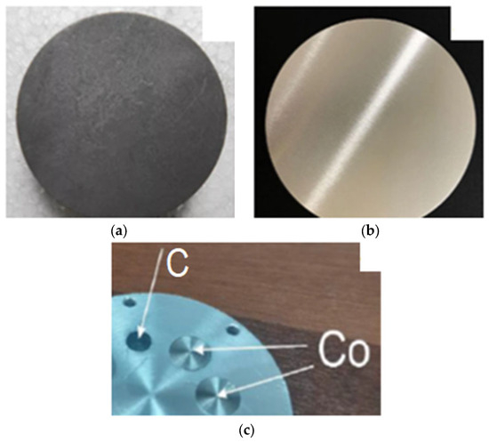
Figure 1.
Targets for magnetron sputtering: (a) graphite target; (b) cobalt target; (c) composite target.
An X-ray phase analysis was carried out on Shimadzu XRD 6000 (Shimadzu Corp., Kyoto, Japan) with a Cu anode Kα (λ = 0.154 nm) using the sliding beam method (shooting angle 15°) in the 2θ range of 20–80°. Due to the low intensity of the peaks, the original signal was approximated by Gaussian curves. Before each analysis, the sample was fixed with glue on an amorphous polycarbonate cuvette. Thin-film samples were analyzed using symmetrical (Bragg–Brentano) geometry, in the 15–70° angle range, and asymmetrical geometry in the 20–50° range (in some cases, 15–70° angle range). The analysis of the interplanar distance (d) and Miller indices (hkl) of the samples was carried out using HighScore Plus software 4.0.
Determination of the structural-phase state and elemental composition was carried out by scanning electron microscopy using a JEOL-2200FS (JEOL Ltd., Tokyo, Japan) with Inca Energy (EDX) (Oxford Instruments, Abington, UK). The accelerating voltage was up to 30 kV; the resolution was up to 3 nm; and the instrument magnification was up to ×300,000. Samples were placed in a mold with a diameter of 30 mm, filled with epoxy filler and dried.
The microstructure of the films was studied by transmission electron microscopy using a JEOL-2200FS microscope (JEOL Ltd., Tokyo, Japan). A multi-stage procedure for sample preparation of a coated sample for subsequent analysis by TEM was carried out by preparing a cross-section. First, scratches were applied using a FinePointDiamondScriber 54467 scriber (TedPella, Redding, CA, USA) onto a backing pad on the back of the sample. Next, the substrate with the film was split along the scratch line on a flat table surface by applying the required pressure force with a scalpel or tweezers. Then, the split pieces were glued together with their front sides (films on substrates), so that the two ends became visible. A layer of wax was applied to the heated surface of a quartz cylinder with a diameter of 5 mm, and the glued samples were attached to the wax with the ends on top. Finally, the samples were subjected to additional thinning using ion etching by Gatan 691 (Gatan, Inc., Pleasanton, CA, USA).
The microhardness of the sprayed coating and the matrix was measured on a Durascan 10 micro-tester (Emcotest, Kuchl, Austria) with a load of 33 mN with a diamond tip in the form of a tetrahedral pyramid. The ratio of the indenter impact depth and the film thickness was less than 10%. The number of measurements performed for each sample was 6. The ambient temperature was 24 ± 5 °C. The relative humidity was 55%.
The surface morphology of the obtained coatings was recorded using NTEGRA Prima atomic force microscope (NT-MDT, Moscow, Russia). The shooting area for all samples was 100 × 100 µm.
Studies of the absorbing characteristics of films were carried out using a P9373A vector equipment network analyzer (Keysight Technologies, Santa Rosa, CA, USA) in the frequency range 300 kHz–14 GHz. The measurement system consisted of the PNA series network analyzer with the Measurement Suite N1500A materials studying software installed on it. Measured parameters: reflection loss (S11/S22 LogMag); standing wave ratio (S11/S22 SWR); reflectance (S11/S22 LinMag); impedance (SmithChart).
Modeling of three-dimensional structures and diffraction patterns of crystals was carried out using a VESTA 3D structure visualizer [29], according to the international database of materials, λ = 0.154 nm. The spatial structure of an ideal crystal was modeled. Based on the Wulff–Bragg condition, the X-ray diffraction of model structures were calculated. X-ray diffractions and interplanar distances of the obtained coatings were compared with the spectra obtained by modeling methods and deviations were identified. In addition, based on the obtained coating spectra, the reverse operation was performed to identify structures from the spectra.
3. Results and Discussion
Figure 2 shows the simulated geometry and X-ray spectra of the Co-C structure using the Vesta 3 software program, which is designed for the 3D visualization of structural models and various volumetric data such as electron/nuclear density and crystal morphology.
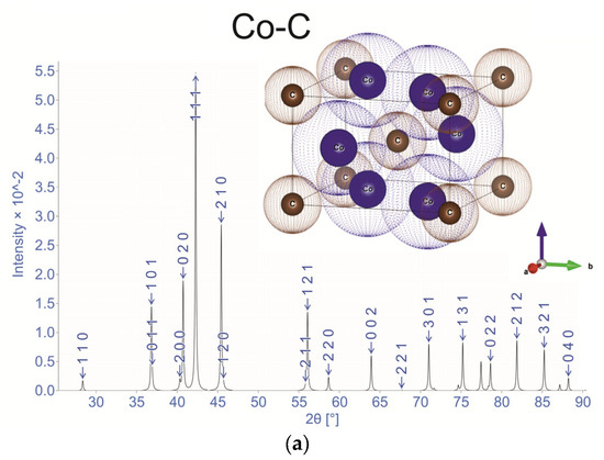
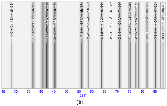
Figure 2.
Structure of Co-C: (a) X-ray diffraction pattern with hkl; (b) X-ray diffraction pattern of the Co-C structure with d-spacing.
Based on the modeling results, it was revealed that the structure is a crystal with an orthorhombic lattice with an atom in the center, which corresponds to FCC lattice: a = 4.469, b = 4.426, c = 2.9107, α = 90, β = 90, γ = 90. Since cobalt is a ferromagnetic material, carbon can affect its magnetic and optical properties. Studying the relative arrangement of atoms in the crystal after deposition will make it possible to study the magnetic and optical properties of Co-C films. This is possible by comparing reference structures and film structures.
Figure 3 and Table 1 show the SEM image of the obtained film and its X-ray diffraction pattern with decoding by the interplanar distance d.
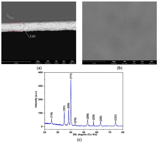
Figure 3.
SEM image of the obtained coating (cross-section SEM): (a) the interface between the coating and the substrate; (b) the microstructure of the surface of the Co-C coating; (c) X-ray diffraction with decoding.

Table 1.
Decoding for X-ray diffraction in Figure 3.
Figure 3a shows the interface between the Co-C coating and the silicon substrate. The coating structure has a granular structure, which may indicate a nanostructured nature of the film. Above the coating, the substrate is more uniform and less granular, which is typical for the structure of single-crystal silicon. The observed interface between the substrate is slightly blurred, indicating good adhesion of the coating to the substrate. Satisfactory adhesion is important for further applicability of the coatings for the mechanical stability and durability of the coating. The thickness of the synthesized Co-C coating was on average 5.0 ± 0.2 μm. Figure 3b shows the surface structure of the coating itself, which looks very dense, fine-grained, and uniform, indicating its highly dispersed structure. The grain size in the structure is almost indistinguishable, indicating the homogeneity of the growth and deposition process of the material during its formation. Figure 3c shows the X-ray diffraction pattern of this sample. The X-ray structural analysis established the main phases and parameters of the interplanar distance d (nm). The resulting Co-C film structure demonstrates identical hkl planes, but with changed d (nm), which indicates the formation of this structure, but with a slightly deformed crystal lattice. However, the resulting structure demonstrates magneto-optical properties, which indicates that the changes in the lattice are in the range of acceptable values. The results of the TEM study of the cross-section of the coating and the corresponding energy-dispersive spectrum are shown in Figure 4.
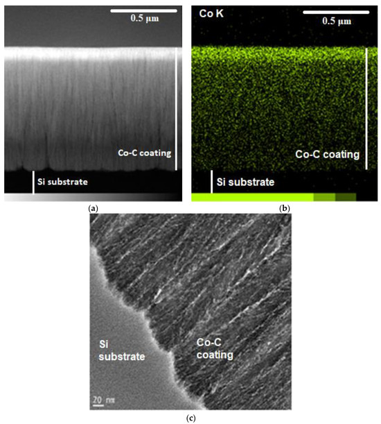
Figure 4.
TEM images of the coating with an energy-dispersive spectrum: (a) general view of the section showing the cross-section of the substrate and coating; (b) energy dispersive spectrum of Co; (c) columnar structure of the coating.
These images taken in the bright field (BF) mode of TEM demonstrate the structure of the coating. It is evident that the Co-C system forms dense coatings with a columnar structure (Figure 4c), typical for metallic coatings. The image shows that the deposition process formed the coating having a high-relief character and looks like a homogeneous layer that adheres well to the substrate, demonstrates a dense structure and clear boundaries between the layers. The coating looks (Figure 4a) layered and dense, indicating a high degree of structural organization, and the absence of defects or inhomogeneities in the image suggests that the material has a homogeneous structure, which is an important indicator for such coatings. TEM studies of the structure showed that the deposition process under the selected modes is accompanied by the formation of a developed interphase boundary between the coating and the substrate, which is clearly visible in Figure 4b. The element distribution map (Figure 4b) obtained by energy-dispersive X-ray analysis (EDX) shows that Co is uniformly distributed throughout the coating. The brightness in the image indicates the concentration of the element: the brighter the area, the higher the cobalt content. It can be seen that cobalt is distributed uniformly throughout the coating, without areas of low or high concentration, which will have a positive effect on its functional characteristics, such as mechanical strength and conductivity. In the high-resolution image with a scale of 20 nm (Figure 4c), one can see that the microstructure of the coating consists of nanocrystalline or amorphous regions. Granular structures or nanocrystals are visible, which are the result of magnetron sputtering of the coating. In general, the structure of the Co-C coating appears to be dense with a uniform distribution of Co and a clear boundary between the coating and the silicon substrate.
Figure 5 and Table 2 show the EDS spectrum of the distribution of the constituent elements of the coating.
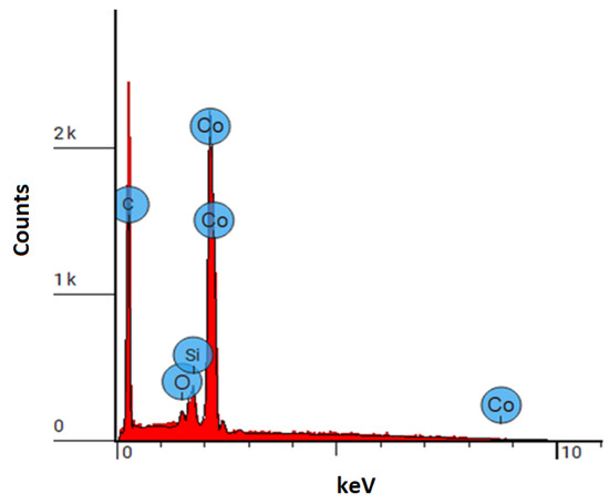
Figure 5.
EDS spectrum of distribution of coating components.
Table 2.
Chemical composition of the obtained coating.
The atomic concentration of Co (14.219%) indicates a significant amount of these atoms in the coating, and the weight concentration of Co (71.928%) suggests that by mass it comprises the main part of the coating, and its high peak in the EDS spectrum confirms its presence in large quantities. The atomic concentration of C was (81.714%), which indicates that carbon dominates by the number of atoms in the coating structure, while its weight concentration is (25.175%), which is due to the low atomic mass of C compared to Co, the peaks of C in the EDS spectrum are also significant, which confirms its main role in the coating. The presence of an oxygen peak in the EDS spectrum is due to its adsorption on the cut surface after removal from the vacuum chamber, low concentrations indicate possible oxidation of the coating or the presence of oxide phases on the coating surface. The presence of Si atoms in the coating is due to its entry from the detection of the substrate itself, since the distribution of silicon atoms by the depth and width of the coating is uniform, while its weight concentration is 2.098%. The silicon peak in the spectrum is small, indicating its presence in the substrate, and not in the coating itself. The data reveal a high content of cobalt and carbon in the coating, which may indicate the formation of a composite Co-C layer on the substrate.
The results of measuring roughness, microhardness, and erosion (abrasive) resistance of the samples are given in Table 3.
Table 3.
Mechanical properties of Co-C coating.
The results of measuring reflection loss (S11/S22 LogMag), standing wave ratio (S11/S22 SWR), and reflection coefficient (S11/S22 LinMag) from a Co-C film sample with a thickness of 4.05–5.50 μm are presented in Figure 6.
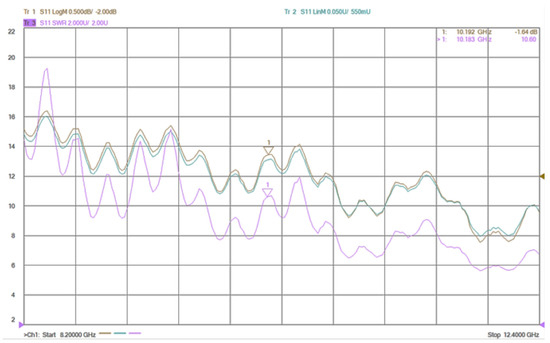
Figure 6.
Change in S11/S22 LogMag, S11/S22 SWR and S11/S22 LinMag in the frequency range of 8.2–12.4 GHz for the Co-C film sample.
In the upper right corner of each graph there are numerical values for three markers: 1—numerical value at the midpoint of the frequency range of 8.2–12.4 GHz; 2—maximum of the measured value; 3—minimum of the measured value. The S11/S22 LogMag shows a general decrease in the signal strength over the frequency range. The S11/S22 SWR shows a similar trend to the LogMag, with peaks at the resonant frequencies, indicating a higher standing wave ratio at these points. The S11/S22 LinMag shows a more gradual decrease in signal strength, with more pronounced peaks at the resonant frequencies. Figure 7 suggests that the Co-C film sample exhibits some resonance behavior in the frequency range of 8.2–12.4 GHz, and the specific resonant frequencies are around 10.192 GHz and 10.183 GHz. The sample’s response in the given frequency range is likely related to the properties of the Co-C film itself.
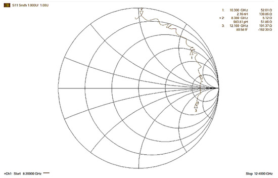
Figure 7.
Change in impedance values in the frequency range 8.2–12.4 GHz for the CoC film sample.
The results of measuring impedance values (SmithChart) from Co-C film are presented in Figure 7 in the form of a Wolpert–Smith chart.
In Figure 7, the scale of the charts is nonlinear. The grid lines correspond to the points of constant active and constant reactance resistances. Points with the same active resistance are located along circles. Points with the same reactance form a set of arcs of different curvature. All resistance values are normalized relative to the wave impedance of the system of 50 Ohm (Z0). In the chart, the grid lines are arranged in such a way that the region of positive active resistances is displayed as a unit circle. The central horizontal axis corresponds to zero reactance. The center of the diagram represents Z/Z0 = 1, which corresponds to the wave impedance of the system. At the left and right intersection points of the horizontal axis with the outer circle, the impedance is zero and infinity, respectively. The outer circle corresponds to zero active resistance. The top and bottom halves of the diagram correspond to a positive and negative reactance, respectively. The value of the impedance modulus for the sample at a frequency of 8.3 GHz is 5.12 Ohm, while at a frequency of 10.3, it increases to 52.0 Ohm, and at 12.1 GHz to 191.37 Ohm.
Thus, the resulting Co-C film at a frequency of 8.3 GHz has a reflection coefficient of 900 mU; at a frequency of 10.3 GHz—805 mU; at a frequency of 12.1 GHz—718 mU. The study of return loss values at 8.4 GHz is −0.86 dB, at 10.3 GHz it is −1.86 dB, and at 12.1 GHz it is −2.57 dB. The standing wave ratio at 8.3 GHz is 19, at 10.3 GHz it is 9.5, and at 12.1 GHz it is 6.8. An analysis of the general graph of the absorbing characteristics of the material indicates the presence of significant losses of electromagnetic energy in the frequency range of 8.2–12.4 GHz. There is a monotonic sinusoidal decrease in the values of the parameters studied with a decrease in amplitude as the frequency of the electric current increases. The observed values of reflection losses are typical for volumetric absorbers of electromagnetic energy.
Based on the obtained data, a comparative analysis of the results was carried out with the data on reflection losses for different materials [30,31,32]. For example, carbon nanotubes at a frequency of 8.0–12.0 GHz show −20 to −50 dB in return losses, which indicates its absorption efficiency in a wide frequency range. Ceria-doped hexaferrites at the same frequency exhibit return losses from −10 to −30 dB, which demonstrates their absorption efficiency in the microwave region. Nanocomposites based on NiFe2O4 at an illogical frequency are characterized by data on reflection losses from −20 to −45 dB, which makes them a promising nanomaterial for the absorption of electromagnetic waves.
Based on the comparison with other types of materials, the CoC-based film we obtained shows relatively low reflection losses in the range of 8.2–12.4 GHz. For comparison, carbon-based nanotubes and ferrites have significantly higher reflection losses from −20 to −50 dB, which indicates a higher efficiency. Nanocomposites based on metal oxides, such as NiFe2O4, also demonstrate better results with losses up to −45 dB.
At the same time, in all cases, the absorbers work effectively in the range of 8–12 GHz, which is often used for absorption efficiency measurements. The results of the CoC film show a gradual increase in reflection losses with increasing frequency, but the values remain significantly lower than those of modern nanocomposites and carbon nanotubes. Nevertheless, the CoC film has a standing wave ratio of 19 at 8.3 GHz, indicating poor impedance matching between the material and the environment. For comparison, highly efficient absorbers, such as ferrites, usually have a lower standing wave ratio, which provides better absorption and less reflection. Reflection loss values of −10 dB and below, in our opinion, can be considered satisfactory for practical use in microwave absorption; i.e., the obtained CoC-based film is suitable for low-loss applications. Further optimization of the obtained material is also required to increase its efficiency as an absorber.
4. Conclusions
A thin-film material based on Co-C was obtained using magnetron sputtering technology. The material is capable of absorbing electromagnetic waves of a certain frequency. The magnetron sputtering method made it possible to obtain structures close to the calculated ones. Based on the modeling data, X-ray diffraction, and electron microscopy, the structure and properties of the film were studied. An X-ray phase analysis established the correspondence of the obtained structures to the simulated structures in VESTA, a 3D structure visualizer software program. The obtained film demonstrates identical HKL planes, but with changed interplanar distances d (nm), which indicates the formation of a structure with a slightly deformed crystal lattice. However, the obtained structure demonstrates magneto-optical properties, which indicates that the changes in the lattice lie in the range of acceptable values. A TEM analysis established that the Co-C coating on the silicon substrate has the following characteristics: visually satisfactory adhesion to the substrate, without visible delamination or cracks; a homogeneous structure, which indicates a high-quality deposition process; a uniform distribution of cobalt, which is critical to ensure stable physical properties of the coating. The reflection coefficient on the resulting CoC film in the frequency range of 8.2–12.4 GHz decreases from 900 to 718 mU, the reflection loss value increases from −0.86 dB to −2.57 dB, and the standing wave ratio changes in the range from 19 to 6.8. The complex electrical resistance of the resulting film with an increase in the frequency from 8.3 to 12.1 GHz increases from 5 to 190 Ohm. The analysis of the obtained data indicates the presence of certain losses of electromagnetic energy in the frequency range of 8.2–12.4 GHz, which occur according to a sinusoidal dependence and decrease with increasing frequency of the electric current. The results of the CoC film show a gradual increase in reflection losses with increasing frequency, but the values remain significantly lower than those of modern nanocomposites and carbon nanotubes.
The obtained data show moderate results in terms of microwave absorption compared to modern high-performance absorbers. Reflection loss values from −10 dB and below are often considered satisfactory for practical use in microwave absorption; i.e., the obtained CoC-based film is suitable for low-loss applications. Importantly, the Co-C system can be modified by changing the cobalt and carbon ratio, as well as adding other components, which will allow the tuning of the radio-absorbing properties of the coating depending on specific requirements. In addition, Co-C-based coatings are relatively easily applied to surfaces using magnetron sputtering, allowing them to be integrated into manufacturing processes without significant modifications. The resulting film shows potential but requires further optimization to achieve reflection losses comparable to nanocomposites and other modern absorbers.
Author Contributions
Conceptualization, N.P. and A.Z. (Almira Zhilkashinova); methodology, N.P., A.Z. (Almira Zhilkashinova) and M.A.; software, I.O. and A.P.; validation, I.O., M.A. and A.M.; formal analysis, A.Z. (Almira Zhilkashinova), A.P. and A.Z. (Assel Zhilkashinova); investigation, N.P., A.Z. (Almira Zhilkashinova), M.A., I.O. and A.P.; resources, A.P.; data curation, I.O. and A.Z. (Assel Zhilkashinova); writing—original draft preparation, A.Z. (Almira Zhilkashinova), M.A. and A.Z. (Assel Zhilkashinova); writing—review and editing, A.M. and T.K.; visualization, I.O. and T.K.; supervision, N.P.; project administration, N.P.; funding acquisition, N.P. All authors have read and agreed to the published version of the manuscript.
Funding
This research was funded by the Science Committee of the Ministry of Science and Higher Education of the Republic of Kazakhstan, grant number AP19680101.
Institutional Review Board Statement
Not applicable.
Informed Consent Statement
Not applicable.
Data Availability Statement
The raw data supporting the conclusions of this article will be made available by the authors on request.
Conflicts of Interest
Author Tilek Kuanyshbekov was employed by the company Kaz Graphene LLP. The remaining authors declare that the research was conducted in the absence of any commercial or financial relationships that could be construed as a potential conflict of interest.
References
- Lan, D.; Li, H.; Wang, M.; Ren, Y.; Zhang, J.; Zhang, M.; Ouyang, L.; Tang, J.; Wang, Y. Recent advances in construction strategies and multifunctional properties of flexible electromagnetic wave absorbing materials. Mater. Res. Bull. 2024, 171, 112630. [Google Scholar] [CrossRef]
- Wu, Y.; Tan, S.; Zhao, Y.; Liang, L.; Zhou, M.; Ji, G. Broadband multispectral compatible absorbers for radar, infrared and visible stealth applications. Prog. Mater. Sci. 2023, 135, 101088. [Google Scholar] [CrossRef]
- Balaji Ananth, P.; Abhiram, N.; Hari Krishna, K.; Nisha, M.S. Synthesis of radar absorption material for stealth application. Mater. Today Proc. 2021, 47, 4872–4878. [Google Scholar] [CrossRef]
- Zheng, S.; Wang, Y.; Wang, X.; Lu, H. Research progress on high-performance electromagnetic interference shielding materials with well-organized multilayered structures. Mater. Today Phys. 2024, 40, 101330. [Google Scholar] [CrossRef]
- Hannachi, E.; Sayyed, M.I.; Slimani, Y.; Elsafi, M. Structural, optical and radiation shielding peculiarities of strontium titanate ceramics mixed with tungsten nanowires: An experimental study. Opt. Mater. 2023, 135, 113317. [Google Scholar] [CrossRef]
- Ashwini, R.; Naveen, C.S.; Onkarappa, H.S.; Virupaxappa, S.B.; Prasanna, G.D. EMI shielding applications of PANI-Ferrite nanocomposite materials: A review. Synth. Met. 2023, 295, 117338. [Google Scholar]
- Shameran, J.S.; Mahmood, W.M. Review on magnetic spinel ferrite (MFe2O4) nanoparticles: From synthesis to application. Heliyon 2023, 9, e16601. [Google Scholar]
- Li, W.; Wei, J.; Wang, W.; Hu, D.; Li, Y.; Guan, J. Ferrite-based metamaterial microwave absorber with absorption frequency magnetically tunable in a wide range. Mater. Des. 2016, 110, 27–34. [Google Scholar] [CrossRef]
- Wen, G.; Zhao, X.; Liu, Y.; Yan, D.; Hou, Z. Electromagnetic wave absorption performance and electrochemical properties of multifunctional materials: Air@Co@Co3Sn2@SnO2 hollow sphere/reduced graphene oxide composites. Chem. Eng. J. 2021, 420, 130479. [Google Scholar] [CrossRef]
- Fang, D.; Liu, S.; Li, J.; Jin, H. Absorber design based on In/C@Co/C composites for efficient microwave absorption. J. Alloys Compd. 2023, 961, 170992. [Google Scholar] [CrossRef]
- Sahu, S.; Mohapatra, P.P.; Singh, H.K.; Dobbidi, P. Enhanced microwave absorbing performance of Sr2+ substituted Nickel-Cobalt nano ferrite for radar and stealth applications. Mater. Sci. Eng. B 2023, 294, 116514. [Google Scholar] [CrossRef]
- He, N.; He, Z.; Liu, L.; Lu, Y.; Wang, F.; Wu, W.; Tong, G. Ni2+ guided phase/structure evolution and ultra-wide bandwidth microwave absorption of CoxNi1-x alloy hollow microspheres. Chem. Eng. J. 2020, 381, 122743. [Google Scholar] [CrossRef]
- Sani, Y.; Azis, R.S.; Ismail, I.; Yaakob, Y.; Mohammed, J. Enhanced electromagnetic microwave absorbing performance of carbon nanostructures for RAMs: A review. Appl. Surf. Sci. Adv. 2023, 18, 100455. [Google Scholar] [CrossRef]
- Ruiz-Perez, F.; López-Estrada, S.M.; Tolentino-Hernández, R.V.; Caballero-Briones, F. Carbon-based radar absorbing materials: A critical review. J. Sci. Adv. Mater. Devices 2022, 7, 100454. [Google Scholar] [CrossRef]
- Abdalla, I.; Cai, J.; Lu, W.; Yu, J.; Li, Z.; Ding, B. Recent progress on electromagnetic wave absorption materials enabled by electrospun carbon nanofibers. Carbon 2023, 213, 118300. [Google Scholar] [CrossRef]
- Maleki, S.T.; Babamoradi, M. Microwave absorption theory and recent advances in microwave absorbers by polymer-based nanocomposites (carbons, oxides, sulfides, metals, and alloys). Inorg. Chem. Commun. 2023, 149, 110407. [Google Scholar] [CrossRef]
- Liu, Q.L.; Zhang, D.; Fan, T.X. Electromagnetic wave absorption properties of porous Carbon/Co nanocomposites. Appl. Phys. Lett. 2008, 93, 013110. [Google Scholar] [CrossRef]
- Shen, H.; Ju, C.; Wang, J.; Huang, H.; Ji, J.; Li, L. Polypyrrole nanoclips-coated Co/C nanostructures with enhanced microwave absorption. Colloids Surf. A Physicochem. Eng. Asp. 2024, 703, 135232. [Google Scholar] [CrossRef]
- Wang, Y.; Li, X.; Han, X.; Xu, P.; Cui, L.; Honghong, Z.; Liu, D.; Wang, F.; Du, Y. Ternary Mo2C/Co/C composites with enhanced electromagnetic waves absorption. Chem. Eng. J. 2020, 387, 124159. [Google Scholar] [CrossRef]
- Duong, T.X.; Tung, D.K.; Khuyen, B.X.; Anh, N.T.N.; Tung, B.S.; Lam, V.D.; Chen, L.; Zheng, H.; Lee, Y. Enhanced electromagnetic wave absorption properties of FeCo-C alloy by exploiting metamaterial structure. Crystals 2023, 13, 1006. [Google Scholar] [CrossRef]
- Jin, Y.; Yu, H.; Wang, Y.; Wang, L.; Nan, B. Recent progress in electromagnetic wave absorption coatings: From design principles to applications. Coatings 2024, 14, 607. [Google Scholar] [CrossRef]
- Xiang, Z.; Zhu, X.; Dong, Y.; Zhang, X.; Shia, Y.; Lu, W. Enhanced electromagnetic wave absorption of magnetic Co nanoparticles/CNTs/EG porous composites with waterproof, flame-retardant and thermal management functions. J. Mater. Chem. A 2021, 9, 17538–17552. [Google Scholar] [CrossRef]
- Pan, Y.; Ma, G.; Liu, X.; Wang, C.; Li, N.; Wang, J.; Jian, X. Electromagnetic and microwave absorption properties of coatings based on spherical and flaky carbonyl iron. J. Mater. Sci. Mater. Electron. 2019, 30, 18123–18134. [Google Scholar] [CrossRef]
- Lu, Y.; Wang, Y.; Li, H.; Lin, Y.; Jiang, Z.; Xie, Z.; Kuang, Q.; Zheng, L. MOF-derived porous Co/C nanocomposites with excellent electromagnetic wave absorption properties. ACS Appl. Mater. Interfaces 2015, 7, 13604–13611. [Google Scholar] [CrossRef]
- Qiang, R.; Du, Y.; Chen, D.; Ma, W.; Wang, Y.; Xu, P.; Ma, J.; Zhao, H.; Han, X. Electromagnetic functionalized Co/C composites by in situ pyrolysis of metal-organic frameworks (ZIF-67). J. Alloys Compd. 2016, 681, 384–393. [Google Scholar] [CrossRef]
- Zhao, D.L.; Zhang, J.-M.; Li, X.; Shen, Z.-M. Electromagnetic and microwave absorbing properties of Co-filled carbon nanotubes. J. Alloys Compd. 2010, 505, 712–716. [Google Scholar] [CrossRef]
- Zhilkashinova, A.; Abilev, M.; Pavlov, A.; Prokhorenkova, N.; Skakov, M.; Gradoboev, A.; Zhilkashinova, A. Ion-plasma spraying and electron-beam treatment of composite Cr-Al-Co-ZrO2-Y2O3 coating on the surface of Ni-Cr alloy. Coatings 2021, 11, 321. [Google Scholar] [CrossRef]
- Skakov, M.; Zhilkashinova, A.; Zhilkashinova, A.; Abilev, M.; Prokhorenkova, N.; Agelmenev, M.; Ismailova, A. Effect of heat treatment on the structural-phase state and properties of a multilayer Co-Cr-Al-Y coating. Crystals 2022, 12, 1056. [Google Scholar] [CrossRef]
- Momma, K.; Izumi, F. VESTA 3 for three-dimensional visualization of crystal, volumetric and morphology data. J. Appl. Crystallogr. 2011, 44, 1272–1276. [Google Scholar] [CrossRef]
- Mosleh, Z.; Kameli, P.; Poorbaferani, A.; Ranjbar, M.; Salamati, H. Structural, magnetic and microwave absorption properties of Ce-doped barium hexaferrite. J. Magn. Magn. Mater. 2016, 397, 101–107. [Google Scholar] [CrossRef]
- Li, W.; Cai, H.; Kang, Y.; Ying, Y.; Yu, J.; Zheng, J.; Qiao, L.; Che, S. High permeability and low loss bioinspired soft magnetic composites with nacre-like structure for high frequency applications. Acta Mater. 2019, 167, 267–274. [Google Scholar] [CrossRef]
- Wang, J.; Huyan, Y.; Yang, Z.; Zhang, A.; Zhang, Q.; Zhang, B. Tubular carbon nanofibers: Synthesis, characterization and applications in microwave absorption. Carbon 2019, 152, 255–266. [Google Scholar] [CrossRef]
Disclaimer/Publisher’s Note: The statements, opinions and data contained in all publications are solely those of the individual author(s) and contributor(s) and not of MDPI and/or the editor(s). MDPI and/or the editor(s) disclaim responsibility for any injury to people or property resulting from any ideas, methods, instructions or products referred to in the content. |
© 2024 by the authors. Licensee MDPI, Basel, Switzerland. This article is an open access article distributed under the terms and conditions of the Creative Commons Attribution (CC BY) license (https://creativecommons.org/licenses/by/4.0/).