Article

Aluminide Coatings by Means of Slurry Application: A Low Cost, Versatile and Simple Technology

by
Alina Agüero
*,
Pauline Audigié
,
Marcos Gutiérrez
,
Cristina Lorente
,
Julio Mora
and
Sergio Rodríguez
INTA-Instituto Nacional de Técnica Aeroespacial, Área de Materiales Metálicos, Ctra. Ajalvir Km 4, 28850 Torrejón de Ardoz, Spain
*
Author to whom correspondence should be addressed.
Coatings 2024, 14(10), 1243; https://doi.org/10.3390/coatings14101243 (registering DOI)
Submission received: 9 August 2024 / Revised: 10 September 2024 / Accepted: 19 September 2024 / Published: 29 September 2024

Abstract

:
The present study focused on demonstrating the versatility of the slurry deposition technique to produce aluminide coatings to protect components from high-temperature corrosion in a broad temperature range, from 400 to 1400 °C. This is a simpler and low-cost coating technology used as an alternative to CVD and pack cementation, which also allows the coating of complex geometries and offers improved and simple repairability for a lot of industrial applications, along with avoiding the use of non-hazardous components. Slurry aluminide coatings from a proprietary water-based-Cr6+ free slurry were produced onto four different substrates: A516 carbon steel, 310H AC austenitic steel, Ti6246 Ti-based alloy and TZM, a Mo-based alloy. The resulting coatings were thoroughly characterised by FESEM and XRD, mainly so that the identification of microstructures and appropriate phases was reported for each coating. The importance of surface preparation and heat treatment as key parameters for the coating final microstructures was also evidenced, and how those parameters can be optimised to obtain stable intermetallic phases rich in Al to sustain the formation of a protective Al2O3 oxide scale. These coating systems have applications in diverse industrial environments in which high-temperature corrosion limits the lifetime of the components.

1. Introduction

Protective coatings contribute to global, social, environmental and technical objectives related to the reduction of material wastage. Indeed, in many industrial sectors, such as the chemical and petrochemical industries, power generation, automotive, aeronautic, aerospace, component fabrication and processing, among others, significant component useful life enhancements are obtained when coatings are used to prevent or retard wear and/or corrosion. Moreover, and along with the resulting economic savings, using coatings contributes indirectly to decreasing CO2 emissions by reducing energy-consuming fabrication processing and also friction and by allowing operations at higher temperatures, which in the power generation sector translates into higher efficiencies.
In particular, aluminide coatings have been used for over 50 years to protect components from high-temperature oxidation and corrosion in several industrial sectors [1,2,3,4]. These are diffusion coatings that result from temperature-induced interdiffusion of Al added to an alloy so that elements from the alloy react with Al, forming intermetallic compounds. In the presence of sufficiently oxidising atmospheres and at temperatures of 600 °C and higher, these coatings develop a protective Al2O3 scale, which is stable and protects the coating and the alloy from undesired oxidation and corrosion.
Indeed, Ti [5,6], Fe [7,8], Ni [9,10], Co [11,12] and Mo [13,14,15] aluminides have been produced. For instance, Ni aluminides deposited on Ni-based superalloys are widely used in the hot section of aeronautic and gas turbines for power generation [16,17,18] as well as in chemical plants against metal dusting [19,20,21]. In parallel, Fe aluminides deposited on ferritic steels have been proposed for steam oxidation protection in power plants [22,23] and for molten nitrates and carbonates corrosion protection in the storage systems of concentrated solar power plants [24,25,26].
Currently, there are several industrially available, reliable coating deposition technologies such as paints, electrochemical and electroless deposition, thermal spray, chemical vapour deposition (CVD), physical vapour deposition (PVD), pack cementation, overlay welding, laser cladding, etc., which differ in the range of materials type and size of components to be coated, processing complexity and certainly cost. The most widely used application technologies to produce aluminide coatings are CVD and pack cementation, which require coating chambers, pumping systems (CVD) and complex metering and monitoring equipment. In addition, the coating processes carried out in these two systems are very time-consuming.
A simpler and lower-cost coating technology that can be used to produce aluminide coatings is based on the application of Al slurries. These are suspensions of Al particles in a solvent (organic or water) containing a binder and other additives to control the slurry stability, rheology, etc. Its ease of application allows for energy savings, improved repairability of coatings, the possibility of easily localised aluminising, and the use of non-hazardous components in the slurry composition. Furthermore, this method is capable of coating complex geometries such as tubes or warped surfaces. These characteristics respond to the industry’s requirements and challenges, including compliance with environmental constraints and the growing tendency to repair components rather than replace them [27].
This family of coatings has been used for ~50 years, particularly in the aeronautic industry, but mainly to repair damaged aluminide coatings produced by CVD or pack cementation locally. In the following years, several studies concluded that this application process was a very good alternative to replace other aluminising methods. For instance, laboratory and engine tests indicated that Si-modified slurry aluminides were a cost-effective alternative to platinum-modified aluminides for turbine components in marine environments [28], and burner rig testing indicated excellent performance under hot corrosion conditions relevant to gas turbines [29]. More slurry aluminide coatings have been produced and characterised on several Fe [30,31], Ni [31,32], Ti [5,31,33] and Mo [34]-based substrates containing different minor alloying elements. For instance, Al slurry coatings were produced on two ferritic-martensitic steels, P91 and VM12, and were exposed to the Solar Salt (a mix of 60% NaNO3 and 40% KNO3) at 580 °C for 10,000 h. The coated steels developed a protective NaAlO2 oxide layer, demonstrating excellent corrosion resistance. In contrast, the uncoated steels suffered severe corrosion, forming a thick, non-protective oxide [35]. Wang et al. studied the performance of Al slurry-coated 316LN stainless steel in lead-bismuth eutectic (LBE) at 550 °C, with both high and low oxygen levels, as LBE is a potential coolant for nuclear reactors. The coated steel exhibited excellent corrosion resistance in both oxygen conditions, maintaining its coating morphology and forming an alumina layer on the surface [36]. Additionally, these coatings performed exceptionally well in a steam atmosphere. Boulesteix et al. [22] evaluated the behaviour of P92 ferritic-martensitic steel and IN-800HT austenitic steel aluminised with slurry in a steam atmosphere at 650 °C. After 2000 h, coated steels showed minimal degradation, forming a protective α-Al2O3 layer, enhancing the performance compared to the uncoated steels, especially for P92. Pedraza et al. also studied the behaviour of austenitic steels HR3C and IN-800HT aluminised with slurry in a steam atmosphere at 650 and 700 °C, where both coated steels showed little degradation after 2000 h of testing, forming a layer of α-Al2O3, although the uncoated steels also showed no significant degradation under these conditions [37]. TP347HFG stainless steel was tested at 700 °C under both atmospheric and supercritical pressures. After 3000 h, the Al slurry-coated steel exhibited enhanced oxidation resistance, forming a stable α-Al2O3 layer. In contrast, the uncoated steel developed a thin Fe2O3 layer at atmospheric pressure, which worsened under supercritical steam conditions [23].
As mentioned, Al slurries have been applied to different substrates and for different separate applications. In the current work, we demonstrate the versatility of this technology, showing coatings applied by an environmentally benign, low-energy consumption process and specifically developed for four different substrate materials which are used in different industrial sectors. We also show how heat treatment is key for the coating final microstructure and how it can be optimised to obtain stable intermetallic phases rich in Al and, therefore, act as reservoirs to generate protective Al2O3. We present the microstructure of the four different slurry aluminide coatings deposited onto A516 carbon steel, 310H AC austenitic steel, Ti6246 Ti-based alloy and TZM, a Mo-based alloy. Each coating process was thoroughly optimised, and the resulting coatings were characterised by field emission electron microscopy (FESEM) and X-ray diffraction (XRD). These coating systems have applications in diverse industrial environments in which high-temperature oxidation and corrosion limit the life of the components.

2. Materials and Methods

2.1. Substrate Materials

Sample coupons (20 × 10 × 3 mm) of A516 carbon steel, 310H AC austenitic steel, Ti6246 titanium alloy and TZM molybdenum-based alloy supplied by Arcelor Mittal, Avilés, Asturias [38], Alleima, Sandviken, Sweden [39] (known as Sandvik when it was supplied), Aubert & Duval, Pamiers, France [40] and Goodfellow, Huntingdon, United Kingdom [41], respectively. The surface preparation of each alloy will be detailed in Section 3.1 as a key parameter of this study. Roughness measurements were conducted before coating. The substrates composition in wt. % are given in Table 1.

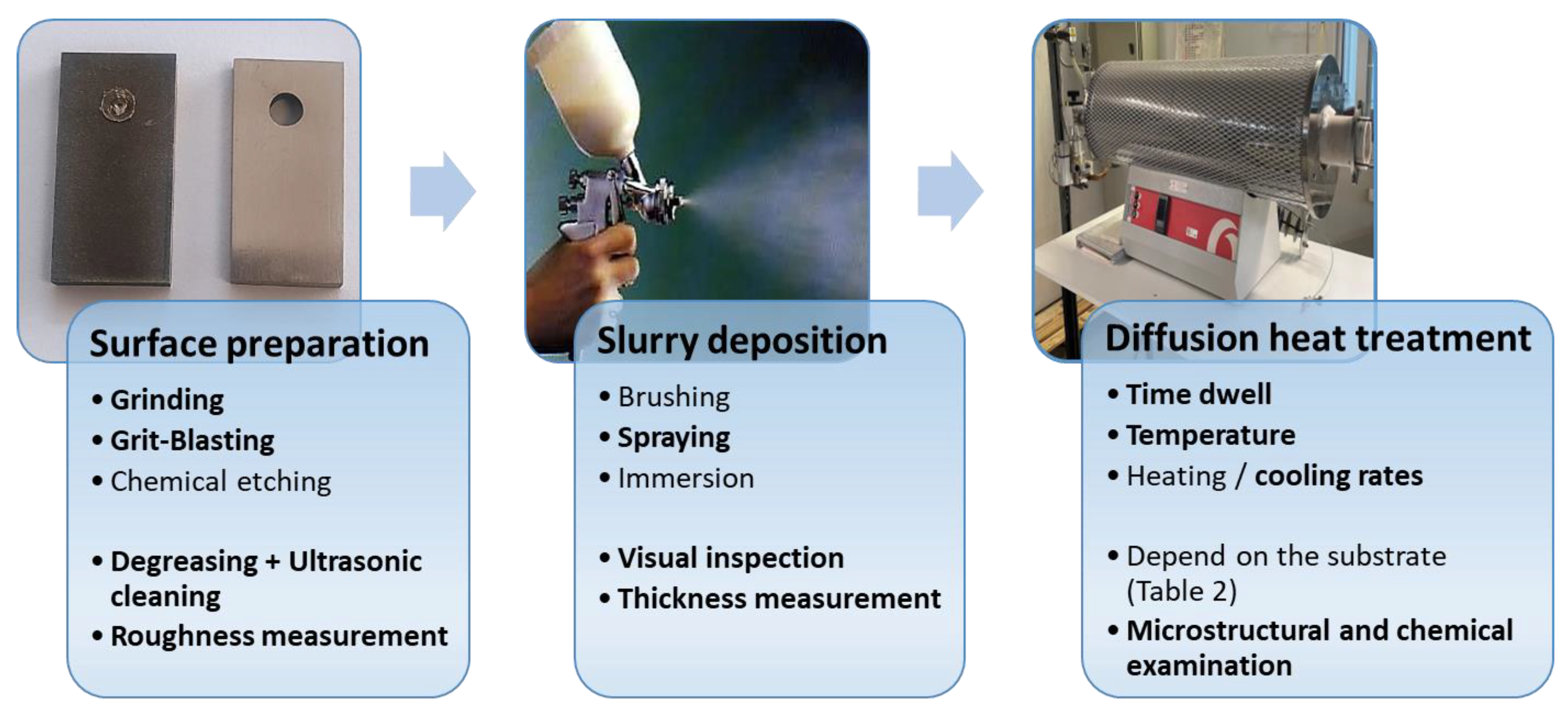
2.2. Coating Application

INTA’s proprietary Al slurry is water-based and fully environmentally benign. Its application methodology has been described elsewhere [42]. After curing, the coated specimens were subjected to a heat treatment that varied with the specific substrate under Ar flow. The diffusion heat treatment of each alloy will be detailed in Section 3.1. After heat treatment, undiffused slurry residues (“bisque”) were removed by slight grinding.

2.3. Characterisation

All the coated and uncoated specimens were characterised after diffusion by light optical microscopy (Leica MEF 4) and Field Emission Scanning Electron Microscopy (FESEM) employing a ThermoScientific APREO C-LV microscope equipped with an energy-dispersive X-ray microanalysis system (EDS) from Aztec Oxford. Crystalline phases present in the coatings were analysed by X-ray diffraction (XRD) in a PANalytical X’Pert PRO MRD diffractometer (Cu Kα1 λ = 1.5406 Å) from 20 to 120° in 2θ, with a 0.5° step and a 2 s holding time, employing Powder Diffraction and Standards databases (JCPDS).

3. Results and Discussion

3.1. Method of Deposition and Importance of Diffusion Heat Treatment

In order to ensure accurate coating deposition via the slurry technique, a series of steps must be followed, as shown in Figure 1. Firstly, it is essential to remove any debris, oxides and grease from the surfaces of the test specimens. This is accomplished through grinding, sand/grit-blasting or chemical etching of the surfaces to be painted, followed by a subsequent cleaning process utilising ethanol in an ultrasound bath for a minimum of 5 min. Once the specimen surface has been prepared, the Al slurry is applied layer by layer with an air spray gun until the desired thickness is reached. The coating thickness can be measured by means of a non-destructible magnetic or eddy current hand-held device. In order to ensure that the paint is applied homogeneously on the surface, the airflow rate, paint flow rate and nozzle width are controlled manually in the laboratory but can be automatised at an industrial scale. Additionally, it is essential to ascertain that the air inlet pressure is between 2 and 3 atm and that the distance to the surface is approximately 15 cm. The coated specimens are left to dry before heat treatment. The last step is a suitable heat treatment, which is essential to produce diffusion coatings without defects and with the appropriate thickness while avoiding any impact on the mechanical properties of the alloy due to potential changes in phases and microstructure. The timing, the temperature and the cooling rate of the heat treatment are crucial for removing stresses between the substrate and the coating, avoiding cracks, and promoting the correct diffusion process. The heat treatment sequence, as well as temperatures and length, depends on the substrate composition. The heat treatments that have been carried out have only been used to generate the coatings described in this paper. When the coating heat treatment temperature causes changes in the alloy microstructure and phase composition, a subsequent heat treatment is needed to restore the original alloy properties. However, in some cases, if the component manufacturing process allows it, the coating process can take place before the corresponding alloy heat treatment, for instance, for the production of ferritic steel tubes. The study of the mechanical behaviour of the alloys is outside the scope of this work, so the heat treatments necessary to restore the mechanical properties of the materials described have not been carried out.
Table 2 gives a detailed account of the main steps illustrated in Figure 1 for the different alloys under study.

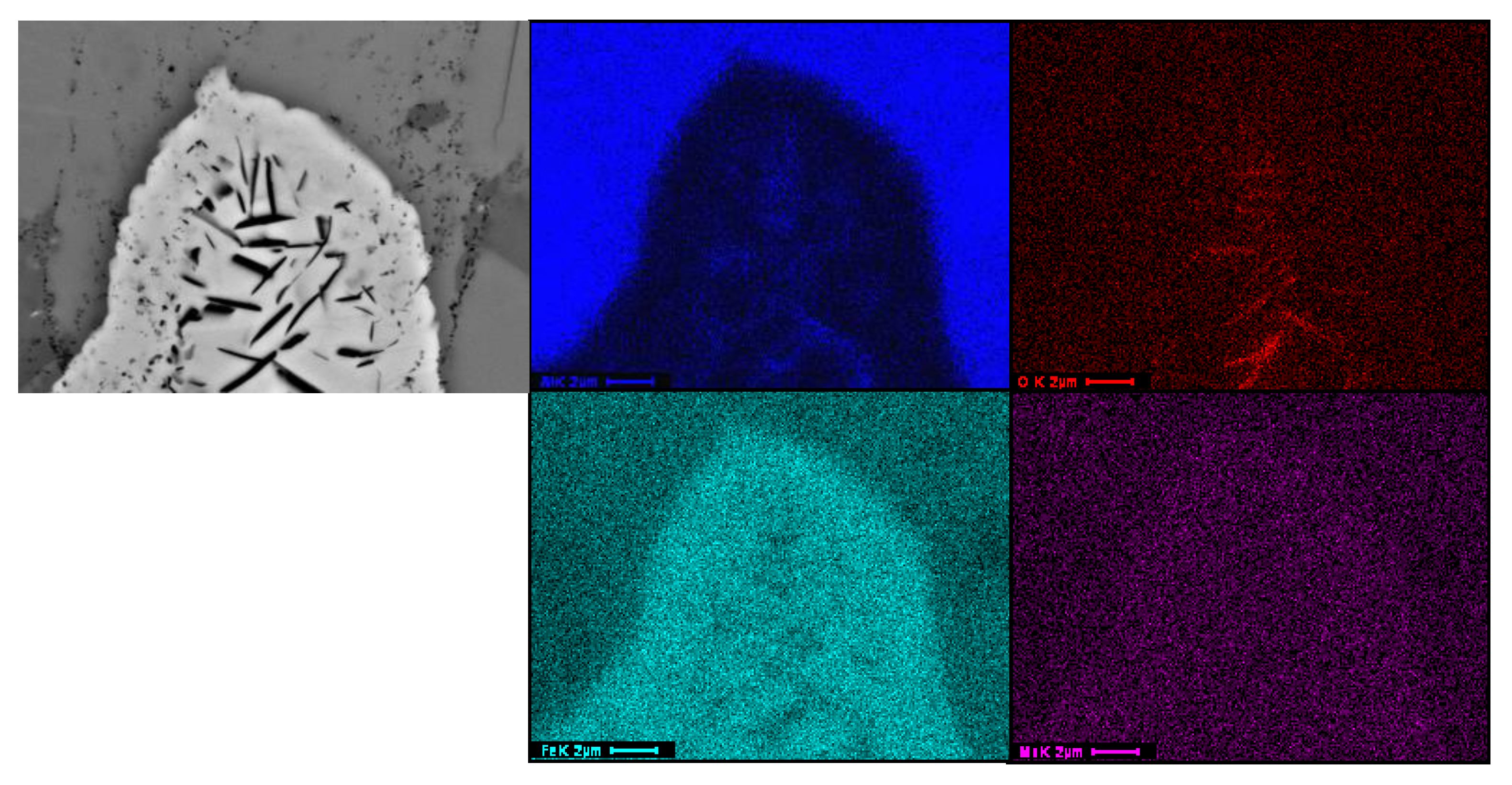
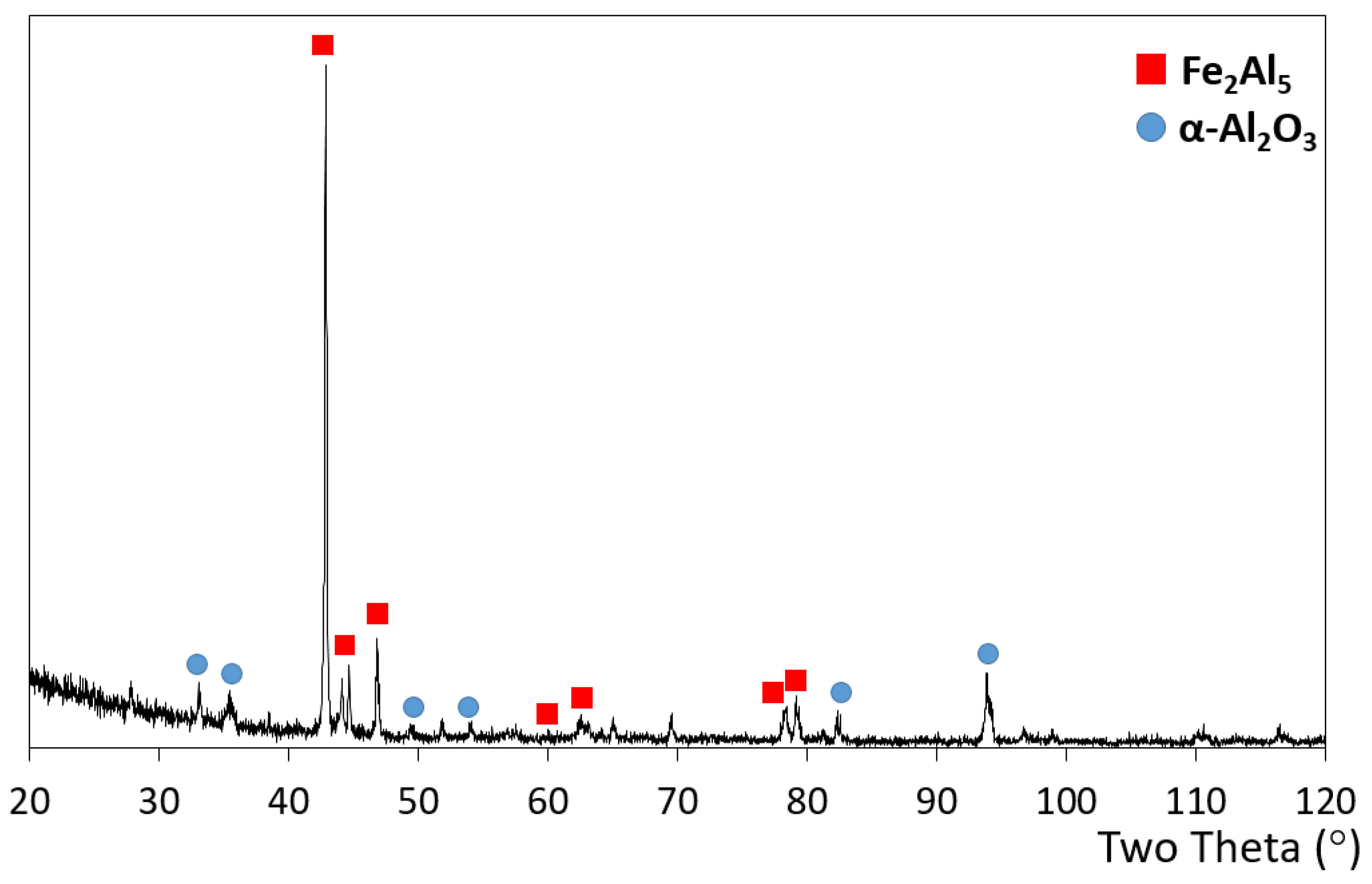
3.2. Microstructure of the Slurry Aluminide Coating Applied on Carbon Steel A516

This material is widely used in various industrial applications such as oil and chemical, medical, and food. Due to its good mechanical properties, A516 Gr70 steel is used in the manufacture of pressure vessels, boilers, heat exchangers, etc. Low-cost carbon steels have been proposed for the construction of the low-temperature portions of the molten salt thermal storage system in solar concentration power plants, in particular, for the lower-temperature tanks in which cooled molten salt coming from a heat exchanger for steam production is stored during the sunless periods. Indeed, carbon steel costs are approximately 10 and 40 times lower than austenitic steels and Ni-based alloys, respectively [43], and can be used up to approximately 455 °C as established by the ASTM code-Section I (applicable for the construction of power boilers) [44]. However, the current typical tank design includes an outer shell of carbon steel separated by a ceramic layer (firebrick) from an inner shell made of higher-cost materials such as SS 304, 316 or 347 austenitic steels to avoid failures related to corrosion [45].
Slurry aluminide coatings were deposited on A516 carbon steel and exposed to molten salts at 580 °C, demonstrating excellent corrosion resistance [24]. A thorough and detailed characterisation of the coating’s microstructure has been undertaken in the present work. Figure 2 shows a cross-section image of the coating obtained on A516 after Al slurry application followed by a 10 h heat treatment at 700 °C under Ar.
The first striking observation is the “wavy” interface with the substrate; as in all other observed aluminides, this interface is smooth. Another interesting feature is the presence of black, acicular precipitates (or platelets) in the inner coating zone (zone 3 in Figure 2), as well as very fine particles, which seem to stem outwards from the larger acicular precipitates all the way to the coating’s surface (Figure 3). Such particles were not observed in any of the slurry aluminides formed on other alloys at any temperature. EDS analysis indicates that the acicular particles are rich in Al, O and Fe (Fe is likely detected due to the proximity of the aluminide matrix with the very thin platelets). The precipitates could, therefore, be Al2O3, which appears black in SEM images, but to present, it has not been possible to determine how and/or why they have formed within this coating. Carbon steels include dissolved oxygen at the ppm level, and MnO inclusions are usually present. It is, however, puzzling why these types of precipitates do not form on another type of steel (ferritic or austenitic). In addition, the precipitates seem to be the cause of the coating-substrate wavy interface, as diffusion is hindered in the areas in which they are more abundant.
Five intermetallic zones can be easily observed by FESEM (Figure 2). EDS analysis indicates a decreasing Al content as a function of the coating depth. The first layer from the surface (zone 1 in Figure 2) is very rich in Al, and its composition measured by EDS corresponds to the Fe2Al5 intermetallic phase, which was also confirmed by XRD (Figure 4). This phase has been repeatedly observed on aluminide coatings deposited on ferritic steels such as P92 when the corresponding interdiffusion heat treatment takes place at 700 °C [46]. Zone 2, the next subjacent phase, which is lighter in colour, corresponds to FeAl2, which has also been observed on ferritic steels but with a significantly lower thickness. Below, there is a thinner layer (zone 3) enclosing the above-mentioned acicular precipitates, which clearly corresponds to cubic FeAl, according to its composition by EDS. Experimental evidence indicates that slurry aluminide coatings form at 700 °C, first by dissolution of the alloy in molten Al, then solidification when intermetallic phases with high melting point form, and finally interdiffusion with the alloy. Zone 3 results from coating substrate interdiffusion, and the fact that the oxide precipitates are concentrated there may indicate that they form as Al from the coating interdiffuses and react with the oxygen-containing substrate at a sufficiently high Al and O content. For example, in ferritic steels containing N, such as P92, acicular AlN precipitates form, but this time below the intermetallic phases, within the substrate immediately below the coating, unto which Al has interdiffusion from the coating [46]. Ultimately, the composition of the following coating layer (zone 4) corresponds to Fe3Al (also cubic), while below, zone 5 seems to be α-Fe, which is a solid solution that can contain up to 45 at. % of Al [47]. Bright precipitate-like phases also appear within the outer Fe2Al5 intermetallic and are likely Si-rich FeAl “islands”. Si and Mn coming from the substrate are present in small amounts in all the intermetallic phases. The XRD pattern shown in Figure 4 also presents small intensity peaks corresponding to α-Al2O3, which likely developed during the heat treatment due to the presence of residual O2 in Ar [48].

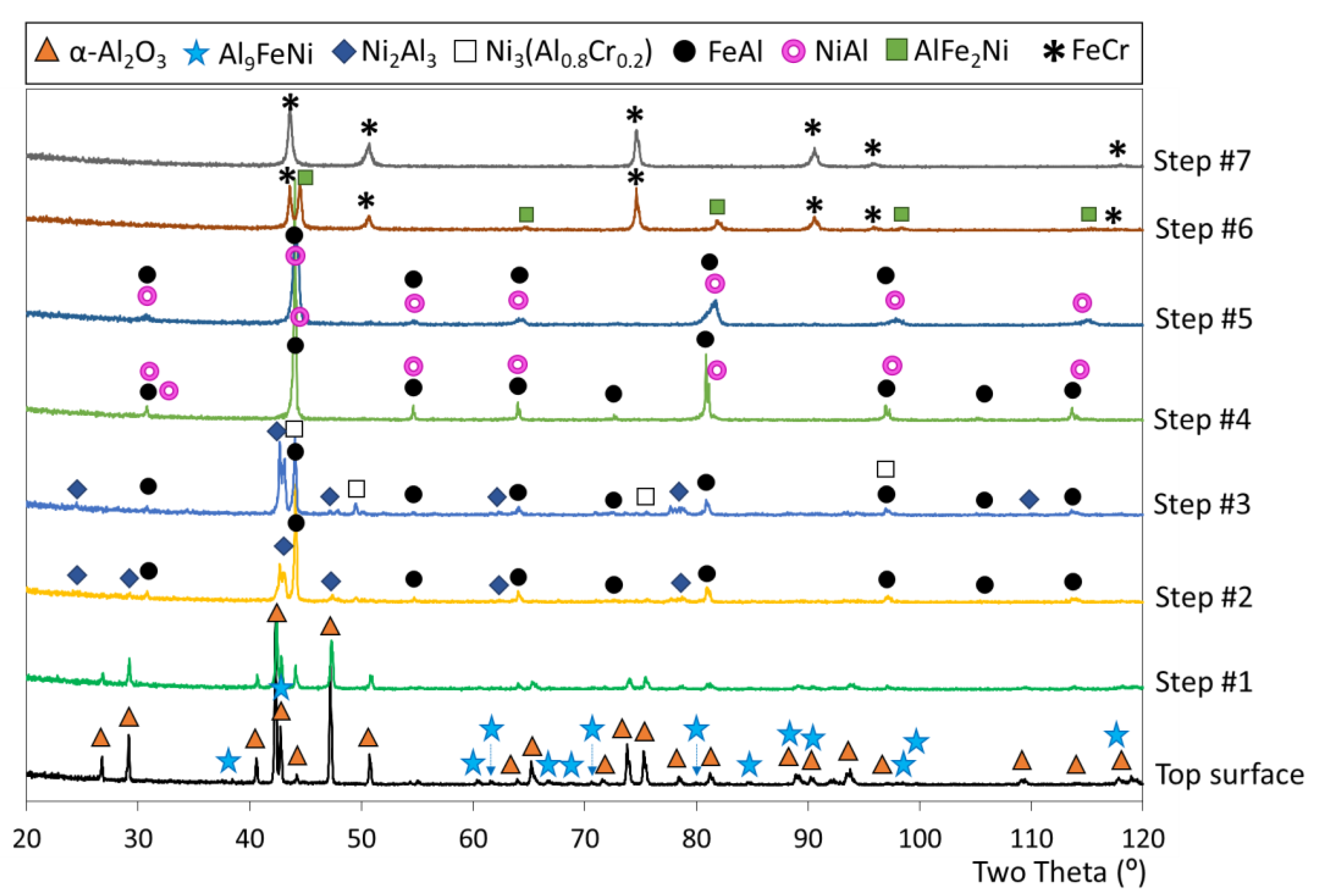
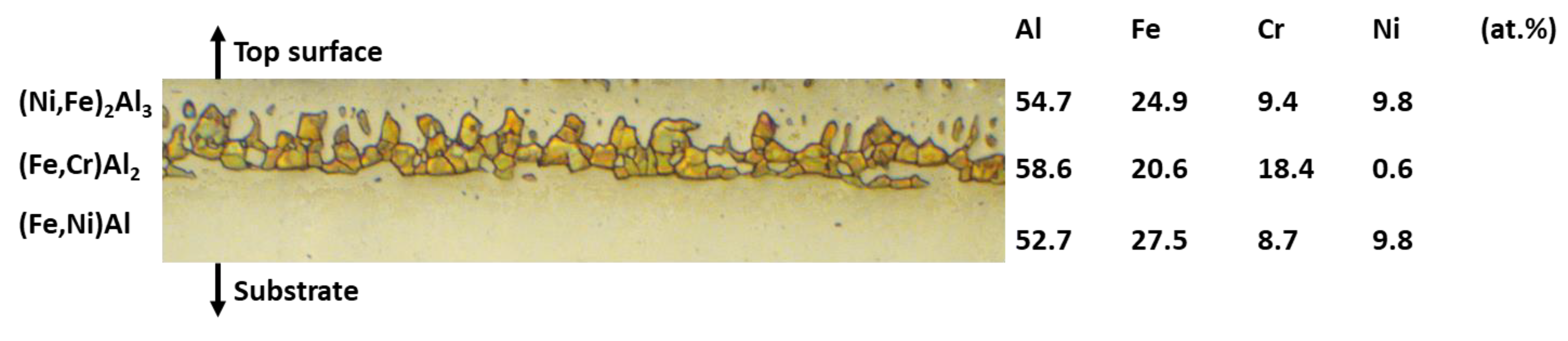
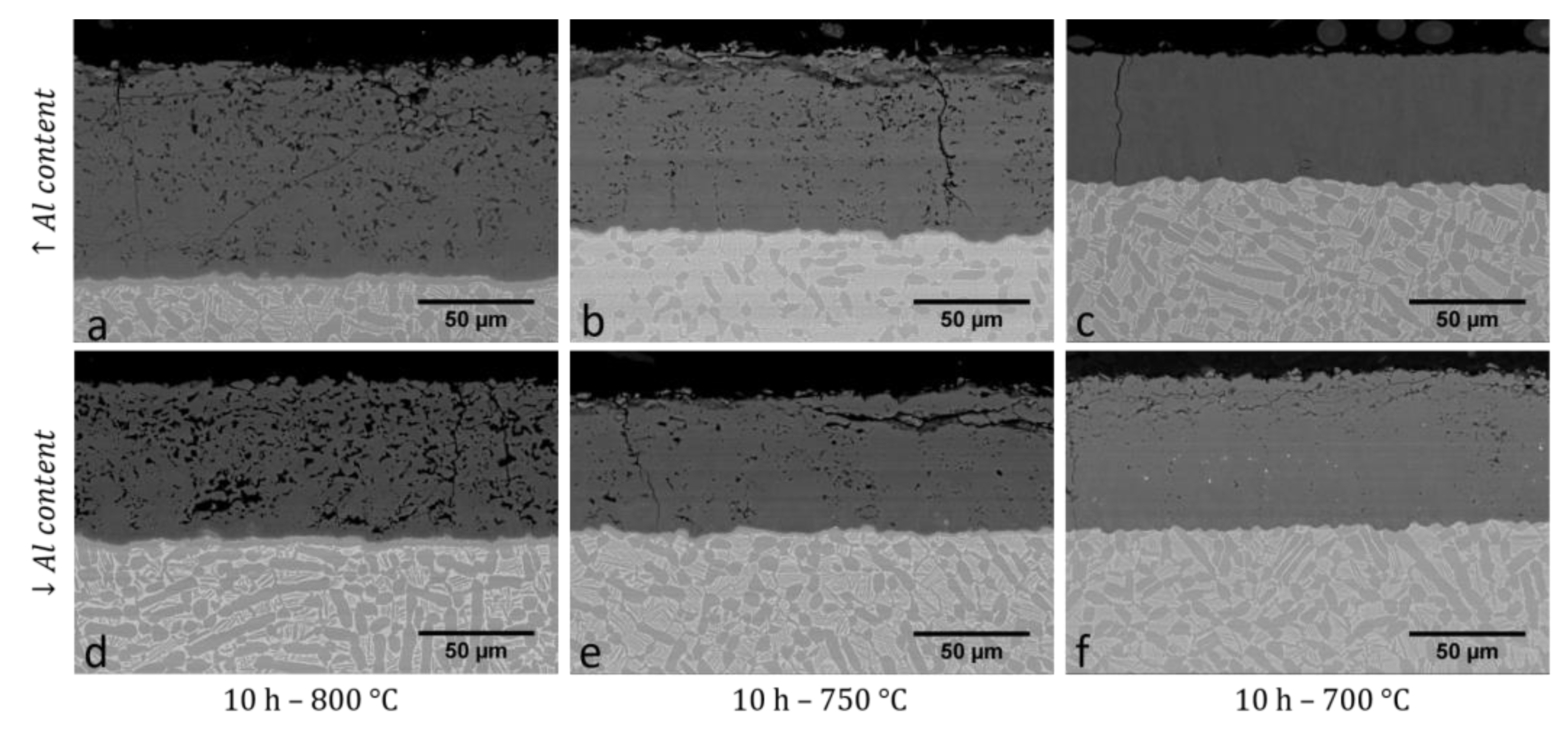
3.3. Microstructure of the Slurry Aluminide Coating Applied on Austenitic Steel 310H

Austenitic stainless steels have been mainly developed for use in high-temperature corrosion resistance and resist oxidation up to 1100 °C under mildly cyclic conditions. The letter “H” for the 310H indicates a high carbon content, which favours carbide precipitation and reduces weldability. 310H was particularly developed for enhanced creep resistance. In addition, when heated between 650 °C and 950 °C, the alloy is subjected to σ phase precipitation. A solution annealing treatment at 1100–1150 °C is necessary to restore an acceptable degree of toughness. It has a wide variety of applications in the food, petrochemical and cement industries. In power generation, it is used in internal components of coal gasifiers, pulverised coal burners and tube hangers. This alloy can work in applications ranging from cryogenic environments (−268 °C) to high-temperature (1100 °C) in mild oxidising, nitriding, carburising and thermal cycling applications [49].
Similar to what has been described for steel A516, slurry aluminide coatings were deposited on 310H steel. For this alloy, the coated specimens were heat treated at 700 °C for 2 h and at 900 °C for 2 h under Ar. This coating has been exposed to molten carbonates at 480 °C, 650 °C and 700 °C, demonstrating excellent corrosion resistance at the three temperatures [50]. The coating’s microstructure was thoroughly analysed in this work, and the meticulous identification of the multiple phases present in the coating was carried out using X-ray diffraction. Figure 5 illustrates the FESEM micrographs and EDS mapping of the coating, while Figure 6 shows the evolution of the XRD patterns of the coated 310H after various slight polishing steps to progressively remove thin coating layers up to 20 μm and contribute to an optimal phase identification.
The coating consists of an 80 μm thick complex microstructure that includes various intermetallic phases rich in Al, Fe, Ni and Cr. The results are presented in the XRD patterns, which were taken after step-wise polishing in order to observe the diffraction patterns of the coating inner zones. These analyses evidenced that the 15 μm thick outermost phase of the coating seems to correspond to Al9Fe(Ni,Cr) with a surface Al concentration of 69 at. %. This phase crystallises in the hexagonal space group P6 3/mmc (No. 194) with a unit cell of dimensions a = b = 7.7094 Å and c = 7.6795 Å [51] but was never reported for aluminide coatings on austenitic steels to the best of our knowledge. As said, Al9Fe(Ni,Cr) was detected as the most coherent phase according to its composition measured by EDS and mainly by XRD.
When examining the isothermal ternary Al-Fe-Ni diagram, Al9FeNi is reported to be stable at temperatures close to 700 °C, and its formation is thus relevant. Kochmanska et al. [52] found that Al5FeNi was the main phase near the surface of the coating when heat treated at 1000 °C after deposition onto the GX20NiCrSi30-18-1 austenitic steel. This phase could also have been formed during our heat treatment, and the composition detected by EDS at the subsurface also matches well. However, no peaks corresponding to Al5FeNi coincide in XRD, and numerous analyses were conducted to support this statement. Because the heat treatment of this present work is slightly lower, it is possible that the Al has diffused to a lesser extent into the coating and, therefore, remained more concentrated on the surface to form the Al9FeNi phase. A thin α-Al2O3 layer was also detected on the top surface of the coating, resulting from the reaction between the deposited Al and the remaining oxygen present in the atmosphere during the heat treatment. This oxide layer has demonstrated its significant influence on the molten Li, Na and K carbonate corrosion resistance of the coating when exposed to 700 °C. Indeed, the presence of this layer in the initial state allowed it to react with Li2O to rapidly form the protective α-LiAlO2 scale, still present after 5000h [50]. The second detected phase (from the surface) was identified as (Fe,Ni)2Al3 by XRD and exhibited lower Al content (54 at. %), whereas Fe amounts to 25 at. % and seems richer in Ni than the previous one. This phase evidences Fe and Ni outward diffusion. The third phase is a 10 μm thick and Ni-free layer, with 58 at. % of Al, 21 at. % of Fe and 18 at. % of Cr and was associated with a Cr-rich FeAl phase thanks to the XRD analysis. According to its composition measured by EDS, this layer can be identified as (Fe,Cr)Al2, and according to the phase diagrams, this phase can be formed and is thermodynamically stable. However, it was not detected by XRD, probably because it is relatively thin and the polishing steps were not sufficiently soft, so it was inadvertently ground before the corresponding pattern could be obtained. It is also important to note that this phase contains a slightly higher Al concentration than the second one and no Ni. As shown in the cross-section optical microscope image after Murakami etching, the phase is constituted by small grains (Figure 7). It is difficult to explain the absence of Ni, but as a hypothesis, this phase may precipitate once it is formed if it is not soluble in the surrounding matrix. Below it, another Al-Fe-Cr-Ni phase with the highest detected Ni concentration (17 at. %) was observed. Three phases, including Ni3(Al0.8Cr0.2), FeAl and NiAl, were also present within the inner part of the coating, again evidencing outward diffusion of the alloying elements to a great extent. Finally, a secondary reaction zone was observed at the coating/substrate interface with Cr-rich phases, which could probably be attributed to the precipitation of the σ-phase but was not observed by XRD, perhaps because the coating was not sufficiently polished to reach this phase. This σ-phase is known to be brittle and not mechanically resistant. However, in terms of diffusion, it seems to act as a diffusion barrier, blocking the inward Al diffusion.
This was notably demonstrated after 5000 h-exposure at 700 °C in molten Li, Na and K carbonate corrosion where up to 48.7 at. % of Al was still maintained in the layers situated above the σ-phase layer [50]. Finally, the two last steps of polishing led to identifying the substrate with the presence of the FeCr phase, as well as another phase, AlFe2Ni, the most inner Al-containing phase, which also contains Cr. Hardness analysis of the different identified phases will be further performed to identify the stress gradient between the coating and the substrate for the mechanical application of this coating.

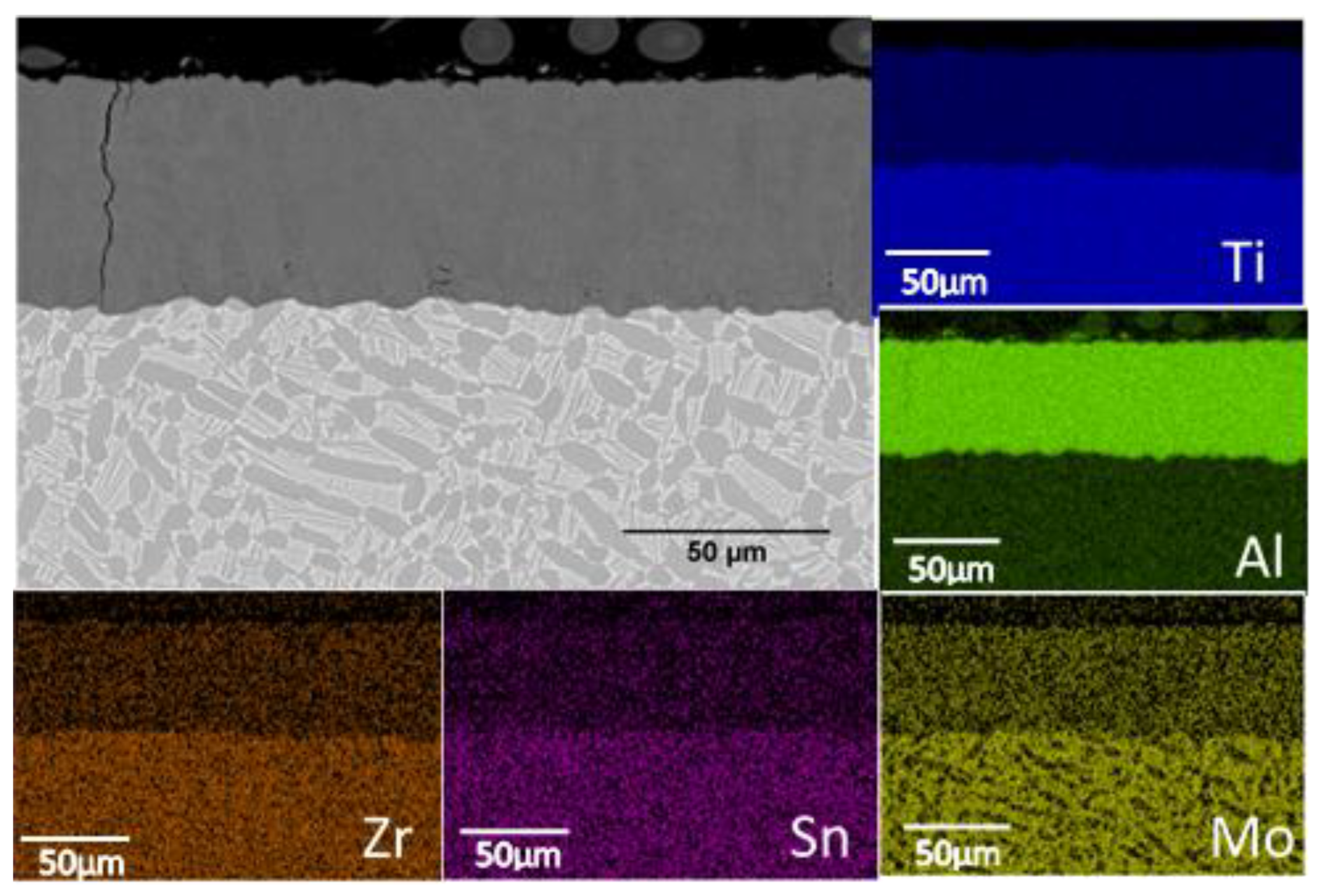
3.4. Microstructure of the Slurry Aluminide Coating Applied on Ti Alloy Ti6246

This material is widely used in the aeronautical, aerospace, oil, gas sectors and automotive industries. Ti alloys are commonly used in the aerospace industry due to their outstanding properties such as low weight, high specific resistance, low density, high corrosion resistance in different environments and good compatibility with carbon fibre-reinforced polymers, becoming excellent candidates to reduce fuel consumption and consequently reduce the greenhouse gases emissions [53,54,55,56].
Interest in these alloys has increased due to their use in turbine blades and other areas of aircraft engines, such as the fan and the compressor in the forehalf section, where temperatures are relatively low. However, Ti alloys cannot be used at temperatures above 550–650 °C due to the high oxygen dissolution, which leads to a lack of oxidation resistance under these conditions, affecting their mechanical properties, particularly the ductility, preventing long-term use as required by the aerospace industry [57].
In general, to achieve effective protective slurry coatings, it is necessary to optimise the composition of the slurry, its deposition process and the heat treatment after deposition. In INTA, coatings have been developed for some time, and the slurry compositions and heat treatments have been optimised. However, we had not studied Ti alloys prior to this work. As previously said, a suitable heat treatment is essential to produce diffusion coatings without defects and with the appropriate thickness while avoiding any impact on the mechanical properties of the alloy due to potential changes in phases and microstructure. The dwell time and the temperature of the heat treatment are crucial, and optimisation is nearly always required to avoid cracks and induce the correct diffusion phenomena. An example of the influence of these factors in the development of coating deposited onto Ti6246 is shown in Figure 8 with heat treatments conducted under argon at 700, 750 and 800 °C. This figure compares coatings with varying Al content and heat treatments after slurry deposition. The results show that decreasing the heat treatment temperature leads to a reduction in porosity, which is likely related to a lower degree of coating substrate interdiffusion and to the fact that the diffusivity of Ti on Al is around six orders of magnitude faster than that of Al in Ti so that Kirkendall voids can form as a result. Cracks are present in the coating regardless of the deposition conditions and are likely to originate during cooling to relieve stresses. Cracks were also observed in Fe aluminide coatings formed on ferritic steels such as P92, but it was shown that said cracks do not propagate nor become sites for corrosive species to reach the substrate as they self-heal by filling themselves with Al2O3 when exposed to corrosive atmospheres such as steam [46] and biomass corrosion atmospheres [42]. The study also highlights the relationship between the metal content in the slurry preparation and the final coating thickness. For the same amount of applied Al slurry, thicker coatings are obtained when the heat treatment temperature is higher due to increased interdiffusion with the substrate elements. In coatings with lower Al content, this effect is not relevant as there is no variation in coating thickness.
A thorough characterisation of the coating’s microstructure has been undertaken for this new coated system. Figure 9 shows the cross-section FESEM image of the coating obtained on Ti6246 after Al slurry spraying followed by a 10 h heat treatment at 700 °C under Ar. The image evidences a homogeneous coating layer, approximately 60 µm thick, with some porosity near the substrate and isolated through-thickness cracks, probably caused by the different thermal expansion coefficients between coating and substrate.
EDS analysis (Table 3) indicates the coating has a constant composition through its thickness, with approximated 69 at. % Al and 23 at. % Ti, coinciding with the TiAl3 phase obtained in the XRD analysis shown in Figure 10. The TiAl3 phase is preferentially formed due to its low free energy and is favourable because it promotes protective Al2O3 formation under high-temperature oxidation conditions due to its high Al content, resulting in selective Al oxidation [58,59].
The aforementioned cracks observed within the coating are likely caused by the difference in thermal expansion coefficients between the TiAl3 phase and the substrate. The TiAl3 phase exhibits a higher coefficient of thermal expansion and a lower degree of ductility, which are characteristics that have been previously identified by other authors [60,61,62]. Consequently, this phase experiences higher volume expansion during the heat treatment process.

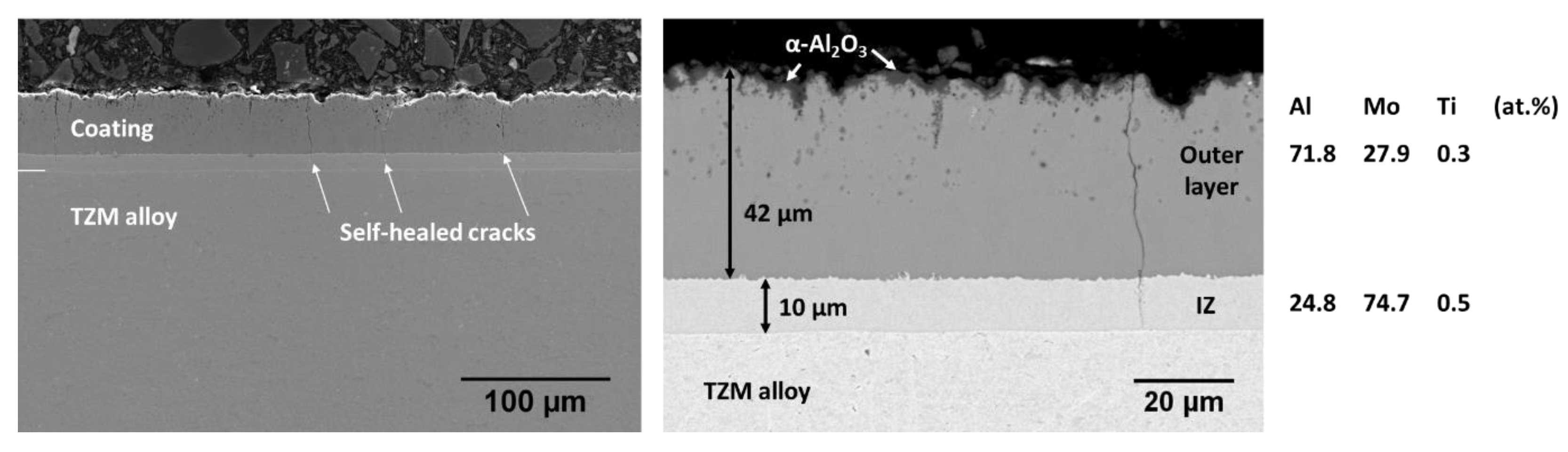
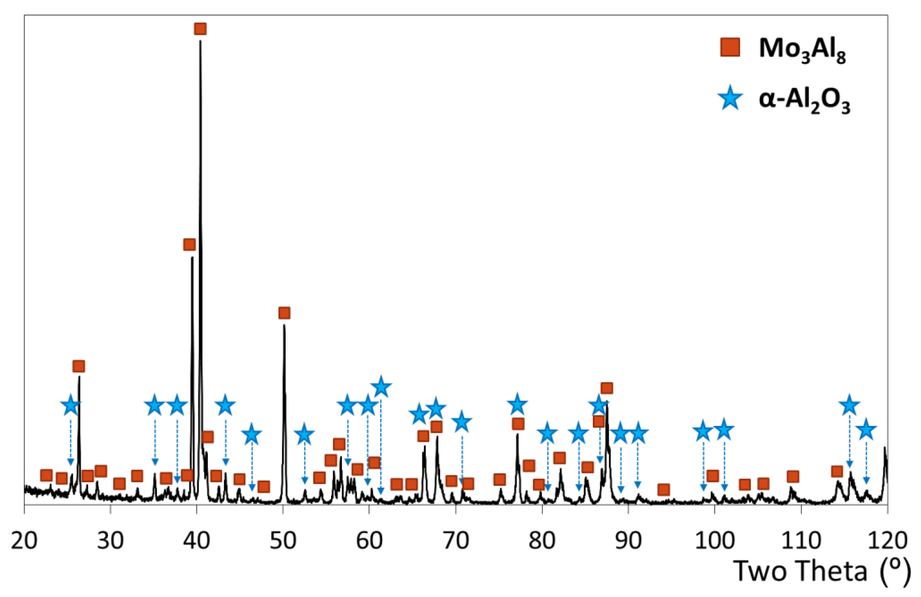
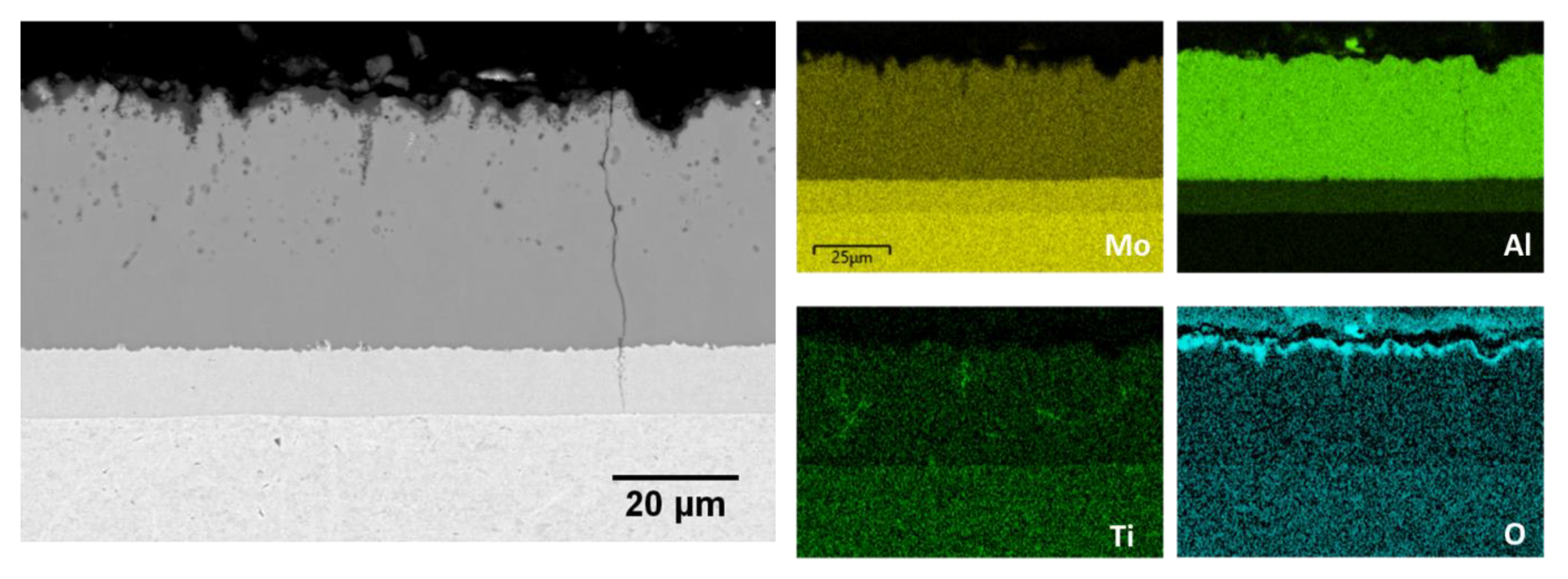
3.5. Microstructure of the Slurry Aluminide Coating Applied on Mo Alloy TZM

TZM Mo alloy has been suggested as a promising alloy in high-temperature applications thanks to its high melting temperature and good mechanical properties, including its high creep and yield strength at elevated temperatures [63]. Its possible use in different industrial fields such as aerospace, nuclear and power plants has driven studies related to its high-temperature corrosion resistance. Some applications of TZM are structural components of heat treatment furnaces, hot runner nozzles, foundry moulds, forging dies, welding electrodes, aluminium foundry moulds, rotating anodes for X-ray tubes, and rocket nozzles. However, it is already known that, when exposed as bare material in oxidising atmospheres above 500 °C, TZM alloy oxidises rapidly, forming MoO3 at around 540 °C, which then volatilises at 790 °C [64]. Moreover, the formation of MoO3 implies a significant volume change and “pesting oxidation” occurs. For these reasons, TZM alloy cannot be used at high temperatures (above 500 °C) without any protection system.
A similar situation arises for the previously described substrates, and protective coatings have been developed on top of TZM to enhance its corrosion resistance. Based on published results on Mo-Si-B alloys, various studies were focused on silicide coatings mainly composed of the MoSi2 phase [34,65]. Even if MoSi2 would favour the formation of the protective SiO2 passive layer at high temperatures, this latter phase is brittle, which leads to extensive volume change during oxidation. Aluminide coatings, by offering an improved oxidation resistance thanks to the formation of a stable, protective and slow-growing α-Al2O3 in the above-mentioned industrial applications, are thus preferable.
For these reasons, an easy-to-apply slurry coating has been deposited on TZM to ensure the formation of stable Mo-Al intermetallics, which, in turn, would form a protective Al2O3 scale at high temperatures. Attention was specifically paid to the development of defect-free coatings not to encourage Mo oxidation and MoO3 volatilisation. TZM surface was first grit blasted with GL80 angular grit, a 100 μm thick aluminide slurry was sprayed, and heat treatment of 2 h at 1200 °C under Ar was conducted to produce the diffusion coating. Figure 11 shows the microstructure of the resulting coating after removal of the slurry residues. The alloy surface was perfectly covered by the produced coating, which is composed of two different layers, both rich in Mo and Al: a 50 μm thick outer layer is formed where the Al concentration reaches 73 at. % on the top surface, while the inner layer corresponds to the 8 μm thick interdiffusion zone (IZ). The external layer has been identified by XRD as Mo3Al8, while the IZ is Mo3Al. The coating also exhibited high surface roughness, similar to that observed on slurry aluminide coatings on ferritic steels [66] was observed. Small voids were also observed in this outer layer, while through-thickness cracks within the coating, which reached the substrate (but did not propagate through it), were observed.
To further reduce the coating roughness and avoid the presence of defects, the surface preparation and the diffusion heat treatment have been optimised to obtain a uniform and defect-free coating. To do so, the sample surface was ground with P180 SiC paper before spraying the same slurry layer thickness. Subsequently, heat treatment of both a slightly lower dwell time and temperature (1 h at 1150 °C instead of 2 h at 1200 °C) under Ar was conducted. The main difference was governed by the cooling rate after heat treatment, which is of major importance in diffusion processes, phase transformations, stress relaxation, and related formation of defects. For this reason, the cooling rate was considerably reduced and controlled to 0.4 °C/min. The resulting microstructure in Figure 12 evidences a more homogeneous coating while maintaining the two layers as the external one composed of Mo3Al8 and the IZ composed of Mo3Al (Figure 13), suggesting that this second tested heat treatment also induced the same phase formation.
The main improvement was related to the coating surface, which was noticeably less rough. Even an α-Al2O3 thin layer was observed on the coating surface and was also revealed by XRD analysis (Figure 13 and Figure 14). Its formation resulted from the reaction between Al from the slurry and the residual O in the atmosphere during the diffusion heat treatment. Ultimately, the extent of void formation within the outer layer was shown to decrease after the second heat treatment. The controlled cooling phase probably allowed Mo and Al diffusion fluxes to be equally compensated, and fewer vacancies were injected or could easily annihilated at dislocations. The slow cooling rate has some effect on the interdiffusion zone because a slightly higher IZ layer thickness was observed, although very good adhesion between all interfaces was maintained. Cracks also seem to self-heal in this IZ layer, and their formation and evolution over time need to be thoroughly studied.
However, two doubts arise when considering this coating. Firstly, the Mo3Al8 outer layer constituting phase will likely offer corrosion resistance thanks to its high Al concentration, but this phase is brittle, so an investigation of the mechanical properties of coated specimens needs to be undertaken. Fe aluminide coatings observed on ferritic steels, also obtained by slurry application, did not significantly affect the mechanical properties of the substrate despite the presence of the same type of cracks and the brittleness of the Fe2Al5 phase which is present in these coatings [66]. Secondly, will the very fine self-healed cracks present in the coating appropriately avoid oxygen penetration during exposure and will the coating sustain its protection mechanism after long-term exposure?

4. Conclusions

The application of Al-containing slurries to produce diffusion aluminide intermetallic coatings has been demonstrated as a versatile process that can be used on a wide variety of alloys and can be tuned to obtain the most beneficial coating composition and microstructure in each case. Indeed, both the thickness and coating microstructure can be modified by adjusting the amounts of deposited slurry and the heat treatment sequence and temperature. Slurry application is simple as it does not require sophisticated equipment other than a spray gun or a vessel for immersion, and the process can be easily automatised by means of robots if desired. Among the many advantages, it allows the coat complex component geometries, small and large in size, to take place either at the component manufacturing site or at the end-user. In addition, the surface cleaning and preparation technologies are compatible with industrial processes. Another advantage is their simple local repair processes if the coatings are damaged. Finally, the slurry formulation and the coating processes employed in this work are environmentally benign and fully comply with the European REACH regulation.

Author Contributions

Conceptualisation, A.A., M.G. and J.M.; Funding acquisition, A.A.; Investigation, A.A., P.A., M.G., C.L., J.M. and S.R.; Methodology, A.A., P.A., M.G., C.L., J.M. and S.R.; Project administration, A.A.; Writing—original draft, A.A., P.A., C.L. and S.R.; Writing—review and editing, A.A., P.A., M.G., C.L., J.M. and S.R. All authors have read and agreed to the published version of the manuscript.

Funding

Part of this work was funded by the Spanish Ministry of Sciences and Innovation and the “Agencia Estatal de Investigación” through the Spanish national project COCO”: Ref: PID2020-115866RB-C21/AEI/10.13039/501100011033 as well as by the European Commission through the project BELENUS GA nº815147.

Institutional Review Board Statement

Not applicable.

Informed Consent Statement

Not applicable.

Data Availability Statement

Data is contained within the article.

Acknowledgments

The authors would like to thank all the suppliers of the base materials and acknowledge Mar Juez Lorenzo for her invaluable contribution to the FESEM images of coated A516. The authors also wish to dedicate the work on Mo-coated systems to Michel Pons from SIMaP, France, for initiating this study, providing the free-of-charge samples, and for the invaluable discussion related to this material.

Conflicts of Interest

The authors declare no conflict of interest. The funders had no role in the design of the study; in the collection, analyses, or interpretation of data; in the writing of the manuscript; or in the decision to publish the results.

References

  1. Zhang, Y. Aluminide Coatings for Power-Generation Applications; Oak Ridge National Lab. (ORNL): Oak Ridge, TN, USA, 2003. [Google Scholar]
  2. Grilli, M.L.; Valerini, D.; Slobozeanu, A.E.; Postolnyi, B.O.; Balos, S.; Rizzo, A.; Piticescu, R.R. Critical Raw Materials Saving by Protective Coatings under Extreme Conditions: A Review of Last Trends in Alloys and Coatings for Aerospace Engine Applications. Materialsed 2021, 14, 1656. [Google Scholar] [CrossRef] [PubMed]
  3. Pint, B.A.; Zhang, Y.; Walker, L.R.; Wright, I.G. Long-term performance of aluminide coatings on Fe-base alloys. Surf. Coat. Technol. 2007, 202, 637–642. [Google Scholar] [CrossRef]
  4. Dosta, S.; Betancor, L.; Barreneche, C. Overview of surface engineering technology to improve the energy efficiency in concentrated solar power (CSP) plants. Sol. Energy Mater. Sol. Cells 2024, 277, 113090. [Google Scholar] [CrossRef]
  5. Goral, M.; Swadzba, L.; Moskal, G.; Jarczyk, G.; Aguilar, J. Diffusion aluminide coatings for TiAl intermetallic turbine blades. Intermetallics 2011, 19, 744–747. [Google Scholar] [CrossRef]
  6. Zeng, S.; Li, F. Research Status of Aluminum Base Coating on Titanium Alloy. Coatings 2023, 13, 1525. [Google Scholar] [CrossRef]
  7. Pint, B.A.; Zhang, Y. Performance of Al-rich oxidation resistant coatings for Fe-base alloys. Mater. Corros. 2011, 62, 549–560. [Google Scholar] [CrossRef]
  8. Deevi, S.C. Advanced intermetallic iron aluminide coatings for high temperature applications. Prog. Mater. Sci. 2021, 118, 100769. [Google Scholar] [CrossRef]
  9. Goward, G.W.; Boone, D.H. Mechanisms of formation of diffusion aluminide coatings on nickel-base superalloys. Oxid. Met. 1971, 3, 475–495. [Google Scholar] [CrossRef]
  10. Nicholls, J. Advances in coating design for high-performance gas turbines. Mrs Bull. 2003, 28, 659–670. [Google Scholar] [CrossRef]
  11. Ren, W.; Li, Q.; Song, J.; Xiao, C.; Xu, Z.; He, L.; Cao, C. Oxidation and microstructure evolution of cobalt aluminide coatings on directionally solidified superalloys during long term exposure at 1000 °C. Mater. Res. Innov. 2014, 18 (Suppl. S4), S4-945–S944-951. [Google Scholar] [CrossRef]
  12. Feng, K.; Li, M.; Chen, M.; Li, Z.; Sha, J.; Zhou, C. Cyclic oxidation behavior of Al-Si coating on new γ′-strengthened cobalt-based superalloy: Experimental study and first-principles calculation. Corros. Sci. 2021, 185, 109422. [Google Scholar] [CrossRef]
  13. Choi, K.; Yang, W.; Baik, K.-H.; Kim, Y.; Lee, S.; Park, J.S. Growth Kinetics and Isothermal Oxidation Behavior of Aluminide Pack Coatings on a Multiphase Mo–Si–B Alloy. Oxid. Met. 2019, 92, 423–437. [Google Scholar] [CrossRef]
  14. Karpe, B.; Prijatelj, K.; Bizjak, M.; Kosec, T. Corrosion properties of aluminized 16Mo3 steel. J. Min. Metall. Sect. B-Metall. 2023, 59, 91–100. [Google Scholar] [CrossRef]
  15. Filipovic, J.; Beck, K.; Kontermann, C.; Galetz, M.; Oechsner, M. Mechanical Characterization Potentials of Aluminide Diffusion Coatings on Molybdenum Substrates. Adv. Eng. Mater. 2024, 26, 2302027. [Google Scholar] [CrossRef]
  16. Pomeroy, M.J. Coatings for gas turbine materials and long term stability issues. Mater. Des. 2005, 26, 223–231. [Google Scholar] [CrossRef]
  17. Audigié, P.; Put, A.R.-V.; Malié, A.; Monceau, D. High-temperature cyclic oxidation behaviour of Pt-rich γ-γ’ coatings. Part I: Oxidation kinetics of coated AM1 systems after very long-term exposure at 1100 °C. Corros. Sci. 2018, 144, 127–135. [Google Scholar] [CrossRef]
  18. Guo, L.; He, W.; Chen, W.; Xue, Z.; He, J.; Guo, Y.; Wu, Y.; Gao, L.; Li, D.; Zhang, Z.; et al. Progress on high-temperature protective coatings for aero-engines. Surf. Sci. Technol. 2023, 1, 6. [Google Scholar] [CrossRef]
  19. Agüero, A.; Gutiérrez, M.; Korcakova, L.; Nguyen, T.T.M.; Hinnemann, B.; Saadi, S. Metal Dusting Protective Coatings. A Literature Review. Oxid. Met. 2011, 76, 23–42. [Google Scholar] [CrossRef]
  20. Agüero, A.; Baraibar, I.; Muelas, R.; Oskay, C.; Galetz, M.; Korner, E. Analysis of an aluminide coating on austenitic steel 800HT exposed to metal dusting conditions: Lessons from an industrial hydrogen production plant. Int. J. Press. Vessel. Pip. 2020, 186, 104129. [Google Scholar] [CrossRef]
  21. Madloch, S.; Galetz, M.C. Microstructural evolution of germanium modified AlSi-slurry coatings on alloy 600 at 620°C in metal dusting environment. Surf. Coat. Technol. 2017, 315, 335–341. [Google Scholar] [CrossRef]
  22. Boulesteix, C.; Pedraza, F.; Proy, M.; Lasanta, I.; de Miguel, T.; Illana, A.; Pérez, F.J. Steam Oxidation Resistance of Slurry Aluminum and Aluminum/Silicon Coatings on Steel for Ultrasupercritical Steam Turbines. Oxid. Met. 2017, 87, 469–479. [Google Scholar] [CrossRef]
  23. Agüero, A.; Baraibar, I.; Gutierrez, M.; Tuurna, S.; Toivonen, A.; Pennila, S.; Auerkari, P. Steam Oxidation of Aluminide-Coated and Uncoated TP347HFG Stainless Steel under Atmospheric and Ultra-Supercritical Steam Conditions at 700 °C. Coatings 2020, 10, 839. [Google Scholar] [CrossRef]
  24. Agüero, A.; Audigié, P.; Rodríguez, S.; Encinas-Sánchez, V.; de Miguel, M.T.; Pérez, F.J. Protective coatings for high temperature molten salt heat storage systems in solar concentration power plants. AIP Conf. Proc. 2018, 2033, 090001. [Google Scholar]
  25. Audigie, P.; Encinas-Sanchez, V.; Rodriguez, S.; Perez, F.J.; Agüero, A. High temperature corrosion beneath carbonate melts of aluminide coatings for CSP application. Sol. Energy Mater. Sol. Cells 2020, 210, 110514. [Google Scholar] [CrossRef]
  26. Meißner, T.M.; Oskay, C.; Bonk, A.; Grégoire, B.; Donchev, A.; Solimani, A.; Galetz, M.C. Improving the corrosion resistance of ferritic-martensitic steels at 600 °C in molten solar salt via diffusion coatings. Sol. Energy Mater. Sol. Cells 2021, 227, 111105. [Google Scholar] [CrossRef]
  27. Kochmanska, A. Aluminide coatings on Inconel 617 obtained by slurry method with inorganic binder. J. Achiev. Mater. Manuf. Eng. 2017, 2, 49–55. [Google Scholar] [CrossRef]
  28. Berry, D.; Meelu, M.C.; McMordie, B.G.; Kircher, T.A. Enhancing Performance of Silicon-Modified Slurry Aluminides on Turbine Components Operating in Marine Environments. In Proceedings of the ASME 1995 International Gas Turbine and Aeroengine Congress and Exposition, Houston, TX, USA, 5–8 June 1995. [Google Scholar]
  29. Kircher, T.A.; McMordie, B.G.; McCarter, A. Performance of a silicon-modified aluminide coating in high temperature hot corrosion test conditions. Surf. Coat. Technol. 1994, 68–69, 32–37. [Google Scholar] [CrossRef]
  30. Agueero, A.; Gutierrez, M.; Muelas, R.; Spiradek-Hahn, K. Overview of steam oxidation behaviour of Al protective oxide precursor coatings on P92. Surf. Eng. 2018, 34, 30–39. [Google Scholar] [CrossRef]
  31. Kochmańska, A.; Kochmański, P. Aluminide Protective Coatings Obtained by Slurry Method. Mater. Sci. Forum 2014, 782, 590–593. [Google Scholar] [CrossRef]
  32. Agüero, A.; Østergård, M.J.L.; Hansson, A.N.; Gutierrez, M. Thermal cyclic resistance and long term inter-diffusion properties of slurry aluminide coatings modified with Si. Results Surf. Interfaces 2022, 6, 100042. [Google Scholar] [CrossRef]
  33. Das, D.K.; Trivedi, S.P. Microstructure of diffusion aluminide coatings on Ti-base alloy IMI-834 and their cyclic oxidation behaviour at 650 °C. Mater. Sci. Eng. A 2004, 367, 225–233. [Google Scholar] [CrossRef]
  34. Kochmańska, A.E.; Jarlaczyńska, A.; Baranowska, J. Formation of Silicide and Silicide-Aluminide Coatings on Molybdenum Alloy during Slurry Cementation Process: Influence of Slurry Volume. Materials 2021, 14, 6940. [Google Scholar] [CrossRef] [PubMed]
  35. Agüero, A.; Audigié, P.; Rodríguez, S. 10,000 h molten salt corrosion testing on IN617, uncoated and aluminide ferritic steels at 580 °C. AIP Conf. Proc. 2020, 2303, 150002. [Google Scholar]
  36. Wang, W.; Zhu, Z.; Yang, L.; Lu, J.; Huang, J.; Tan, J.; Kuang, W. Superior corrosion resistance of a slurry FeAl coating on 316LN stainless steel in 550 °C liquid lead-bismuth eutectic. Corros. Sci. 2024, 227, 111757. [Google Scholar] [CrossRef]
  37. Pedraza, F.; Boulesteix, C.; Proy, M.; Lasanta, I.; de Miguel, T.; Illana, A.; Perez, F.J. Behavior of Slurry Aluminized Austenitic Stainless Steels under Steam at 650 and 700 °C. Oxid. Met. 2017, 87, 443–454. [Google Scholar] [CrossRef]
  38. ArcelorMittal Asturias en Avilés | ArcelorMittal España. Available online: https://spain.arcelormittal.com/ (accessed on 4 September 2024).
  39. Alleima® 7RE10—Alleima. Available online: https://www.alleima.com/en/products/ (accessed on 4 September 2024).
  40. 6246—Aubert & Duval English. Available online: www.aubertduval.com (accessed on 4 September 2024).
  41. Molybdenum Alloys | Goodfellow—TZM Molybdenum Alloy | Material: TZM Molybdenum Alloy. Available online: https://www.fonlinkmetal.com/products/molybdenum/tzm_alloy_and_piercing_plug.html?gad_source=1&gclid=EAIaIQobChMI1ezQy77fiAMVpqpmAh2PFTD9EAAYAyAAEgJqXvD_BwE (accessed on 4 September 2024).
  42. Gutierrez, M.; Illana, A.; Bahillo, A.; Benito, M.J.; Garcia-Martin, G.; Perez, F.J.; Aguero, A. Comparison between pilot and lab scale testing of aluminide coated and uncoated ferritic steels under oxy-fuel and coal/thistle co-firing conditions. Surf. Coat. Technol. 2022, 450, 128982. [Google Scholar] [CrossRef]
  43. Palacios, A.; Navarro, M.E.; Jiang, Z.; Avila, A.; Qiao, G.; Mura, E.; Ding, Y. High-temperature corrosion behaviour of metal alloys in commercial molten salts. Sol. Energy 2020, 201, 437–452. [Google Scholar] [CrossRef]
  44. Applicability & Allowable Stress of ASTM A516 Gr.70. Available online: www.metalspiping.com (accessed on 3 August 2022).
  45. Ladkany, S.G.; Culbreth, W.; Loyd, N. Molten Salts and Applications II: 565 °C Molten Salt Solar Energy Storage Design, Corrosion, and Insulation. J. Energy Power Eng. 2018, 12, 517–532. [Google Scholar]
  46. Agüero, A.; Spiradek, K.; Höfinger, S.; Gutiérrez, M.; Muelas, R. Microstructural Evolution of Slurry Fe Aluminide Coatings during High Temperature Steam Oxidation. Mater. Sci. Forum 2008, 595–598, 251–259. [Google Scholar] [CrossRef]
  47. Du, H.; Tan, N.; Fan, L.; Zhuang, J.; Qiu, Z.; Lei, Y. Formation Mechanism of Aluminide Diffusion Coatings on Ti and Ti-6Al-4V Alloy at the Early Stages of Deposition by Pack Cementation. Materialsed 2019, 12, 3097. [Google Scholar] [CrossRef]
  48. Madhavan, N.; Brooks, G.A.; Rhamdhani, M.A.; Rout, B.K.; Schrama, F.N.H.; Overbosch, A. General mass balance for oxygen steelmaking. Ironmak. Steelmak. 2021, 48, 40–54. [Google Scholar] [CrossRef]
  49. Acero inoxidable 310/310S/310H, aleación 310 (UNS S31000/S31008/S31009) (allianzsteel.com). Available online: https://es.allianzsteel.com/serve/stainless-steel-310-310s-310h.html (accessed on 1 September 2024).
  50. Audigié, P.; Rodríguez, S.; Agüero, A. Improved Corrosion Resistance of Slurry Coated Austenitic Steel in Molten Carbonates Doped with Nanoparticles for Thermal Energy Storage Technologies. Poster Commun. 2024. [Google Scholar]
  51. Chumak, I.; Richter, K.W.; Ipser, H. The Fe–Ni–Al phase diagram in the Al-rich (>50at.% Al) corner. Intermetallics 2007, 15, 1416–1424. [Google Scholar] [CrossRef]
  52. Kochmańska, A.E. Microstructure of Al-Si Slurry Coatings on Austenitic High-Temperature Creep Resisting Cast Steel. Adv. Mater. Sci. Eng. 2018, 2018, 5473079. [Google Scholar] [CrossRef]
  53. Boyer, R.R. Titanium for aerospace: Rationale and applications. Adv. Perform. Mater. 1995, 2, 349–368. [Google Scholar] [CrossRef]
  54. Boyer, R.R. An overview on the use of titanium in the aerospace industry. Mater. Sci. Eng. A 1996, 213, 103–114. [Google Scholar] [CrossRef]
  55. Peters, M.; Kumpfert, J.; Ward, C.H.; Leyens, C. Titanium alloys for aerospace applications. Adv. Eng. Mater. 2003, 5, 419–427. [Google Scholar] [CrossRef]
  56. Najafizadeh, M.; Yazdi, S.; Bozorg, M.; Ghasempour-Mouziraji, M.; Hosseinzadeh, M.; Zarrabian, M.; Cavaliere, P. Classification and applications of titanium and its alloys: A review. J. Alloys Compd. Commun. 2024, 3, 100019. [Google Scholar] [CrossRef]
  57. Berthaud, M.; Popa, I.; Chassagnon, R.; Heintz, O.; Lavková, J.; Chevalier, S. Study of titanium alloy Ti6242S oxidation behaviour in air at 560 °C: Effect of oxygen dissolution on lattice parameters. Corros. Sci. 2020, 164, 108049. [Google Scholar] [CrossRef]
  58. Školáková, A.; Salvetr, P.; Leitner, J.; Lovaši, T.; Novák, P. Formation of Phases in Reactively Sintered TiAl3 Alloy. Molecules 2020, 25, 1912. [Google Scholar] [CrossRef]
  59. Shen, Z.; Zhang, Y.; Yu, X. Interfacial microstructure evolution mechanism of high temperature oxidation-resistant Al-based coating on Ti alloy surface. Mater. Res. Express 2019, 6, 086472. [Google Scholar] [CrossRef]
  60. Smialek, J.L. Oxidation behaviour of TiAl3 coatings and alloys. Corros. Sci. 1993, 35, 1199–1208. [Google Scholar] [CrossRef]
  61. Yuan, M.; Wang, Z.; Yao, Y.; Li, L. Finite element analysis of thermal stresses in Ti-Al3Ti metal-intermetallic laminated composites. Results Phys. 2019, 15, 102706. [Google Scholar] [CrossRef]
  62. Wang, J.; Kong, L.; Li, T.; Xiong, T. A novel TiAl3/Al2O3 composite coating on γ-TiAl alloy and evaluating the oxidation performance. Appl. Surf. Sci. 2016, 361, 90–94. [Google Scholar] [CrossRef]
  63. Sharma, I.G.; Chakraborty, S.P.; Suri, A.K. Preparation of TZM alloy by aluminothermic smelting and its characterization. J. Alloys Compd. 2005, 393, 122–127. [Google Scholar] [CrossRef]
  64. Smolik, G.R.; Petti, D.A.; Schuetz, S.T. Oxidation and volatilization of TZM alloy in air. J. Nucl. Mater. 2000, 283–287, 1458–1462. [Google Scholar] [CrossRef]
  65. Alam, M.Z.; Venkataraman, B.; Sarma, B.; Das, D.K. MoSi2 coating on Mo substrate for short-term oxidation protection in air. J. Alloys Compd. 2009, 487, 335–340. [Google Scholar] [CrossRef]
  66. Agüero, A.; Muelas, R.; Pastor, A.; Osgerby, S. Long exposure steam oxidation testing and mechanical properties of slurry aluminide coatings for steam turbine components. Surf. Coat. Technol. 2005, 200, 1219–1224. [Google Scholar] [CrossRef]
Figure 1. Overview of the coating deposition process with the main steps.
Coatings 14 01243 g001
Figure 2. FESEM image of a slurry applied aluminide coating on A516 carbon steel. Compositions were measured by EDS analysis.
Coatings 14 01243 g002
Figure 3. FESEM image of the FeAl zone where the black acicular precipitates accumulate and EDS element mapping.
Coatings 14 01243 g003
Figure 4. X-ray diffraction pattern of the optimised slurry aluminide coating deposited onto A516 alloy.
Coatings 14 01243 g004
Figure 5. FESEM image of a slurry applied aluminide coating on 310H austenitic steel and its corresponding EDS elemental mapping.
Coatings 14 01243 g005
Figure 6. Evolution of the XRD diffraction patterns of the slurry applied aluminide coating on 310H austenitic steel after various slight polishing steps.
Coatings 14 01243 g006
Figure 7. Cross-section optical microscope image of the slurry applied aluminide coating on 310H austenitic steel after Murakami etching, with EDS point analysis in the three different layers.
Coatings 14 01243 g007
Figure 8. Effect of higher Al contents (ac) and lower Al contents (df) at different heat treatments on deposited coatings onto Ti6246.
Coatings 14 01243 g008
Figure 9. FESEM image of a slurry applied aluminide coating on Ti6246 Ti alloy and EDS elemental mapping.
Coatings 14 01243 g009
Figure 10. X-ray diffraction pattern of the slurry aluminide coating onto Ti6246.
Coatings 14 01243 g010
Figure 11. FESEM image of a slurry applied aluminide coating on TZM alloy after 2h at 1200 °C under Ar.
Coatings 14 01243 g011
Figure 12. FESEM observation of the optimised slurry aluminide coating produced on TZM alloy after 1 h at 1150 °C under Ar and controlled cooling rate.
Coatings 14 01243 g012
Figure 13. X-ray diffraction pattern of the optimised slurry aluminide coating deposited onto TZM alloy.
Coatings 14 01243 g013
Figure 14. FESEM image and EDS elemental mapping of the optimised slurry aluminide coating produced on TZM alloy.
Coatings 14 01243 g014
Table 1. Alloys nominal composition (wt. %).
FeCrNiSiVSMoCCoNbNWMnCuTiAlSnZrP
A516Bal.0.300.300.400.020.030.080.20----1.400.30-----
310HBal.25190.5-0.00060.40.04----1.5-----0.023
Ti6246------6-------Bal.624-
TZM------Bal.-------0.5--0.1-
Table 2. Details of the coating deposition process for the different alloys under study.
AlloySurface PreparationSlurry Deposition MethodDiffusion Heat
Treatment
Ra (µm)
A5161. Grit blasting
(F46 corundum)
2. Grinding
(P180 SiC paper)
3. Ultrasonic cleaning
0.319Spraying10 h—700 °C
Argon
310H1. Grinding
(P180 SiC paper)
2. Ultrasonic cleaning
0.524Spraying2 h—700 °C
+ 2 h—900 °C
Argon
Ti62461. Grinding
(P180 SiC paper)
2. Ultrasonic cleaning
0.407Spraying10 h—700 °C
Argon
TZM1. Grit blasting
(GL80 angular grit)
2. Ultrasonic cleaning
3.823Spraying2 h—1200 °C
Argon
TZM
optimised process
1. Grinding
(P180 SiC paper)
2. Ultrasonic cleaning
0.587Spraying1 h—1150 °C
Argon
Table 3. EDS analysis (at. %) at randomly taken zones on Ti6246 coating.
Point1234
O5.504.945.516.09
Al69.6470.1569.8669.19
Ti23.6023.3223.0723.22
Zr0.580.570.610.54
Mo0.651.020.940.88
Sn0.0400.020.08
Disclaimer/Publisher’s Note: The statements, opinions and data contained in all publications are solely those of the individual author(s) and contributor(s) and not of MDPI and/or the editor(s). MDPI and/or the editor(s) disclaim responsibility for any injury to people or property resulting from any ideas, methods, instructions or products referred to in the content.

