Abstract
The aerospace industry has made extensive use of titanium alloy material due to its exceptional qualities, which include high strength, low weight, and resistance to corrosion. However, these qualities also pose challenges for the material’s processing. This article examined the coated end mills for Ti6Al4V milling. First, an analysis was conducted on the solubility of Ti and Si elements. It was discovered that W and Co elements were far more soluble in Ti than Si and Zr elements, which could effectively stop element diffusion. Next, the base’s composition was planned. It was discovered that when the amount of Al increased, the base’s surface roughness increased, while its hardness and elastic modulus decreased. The binding force between the substrate and the base was greater at a 50:50 Ti:Al ratio. The H3/E2 was about 0.23 and the surface roughness was about 0.15 μm. TiSiN and TiSiN/ZrN functional layer properties were also examined. When Zr was added to TiSiN/ZrN coating, it improved the coating’s hardness and elastic modulus, increased density, and decreased surface roughness and friction coefficient when compared to TiSiN coating. There was an increase in hardness by 8.09% and an increase in elastic modulus by 9.65%. The average coefficient of friction decreased from 0.315 to 0.299. Lastly, an analysis of the initial and intermediate tool wear was done using the Ti6Al4V milling experiment. It was discovered that adding Zr element could successfully extend the tool’s cutting life by preventing adhesive wear.
1. Introduction
Titanium alloy has the advantage of high specific strength, excellent corrosion resistance, strength retention at high temperatures and good biological adaptability. It has been widely used in various industries, such as aerospace and biomedical engineering. Titanium alloys can be divided into α-phase or near-α-phase, α + β-phase and β-phase or near-β-phase according to different microstructures. Among them, Ti6Al4V is the most widely used α + β phase titanium alloy and has excellent comprehensive properties. However, these excellent properties also bring difficulties to its processing. With the development of metal cutting technology, more efficient, environmentally friendly and cost-saving cutting methods are being developed. Among them, the coating can not only effectively inhibit the occurrence of mechanical wear, adhesive wear, diffusion wear, oxidation wear and other phenomena, but also reduce the friction coefficient and delay temperature diffusion. Ultimately, long-lasting, efficient and high-quality processing is achieved. Therefore, research on coating becomes particularly important. At present, the research on coating technology has mainly been focused on physical vapor deposition (PVD) coating and chemical vapor deposition (CVD) coating, which have developed from single layer to multi-layer and even composite coating. Coating thickness has also been increasing, from micron scale to nano scale development. Coating material research includes binary TiN, TiC coatings, ternary TiCN, TiAlN coatings, multi-component Cr series, Zr series, B series, Ta series, diamond and diamond-like coatings, etc.
Regarding the research on titanium alloy cutting tool coating materials, Jawaid et al. used the PVD method to coat with TiN coating and process TC4 [1]. They found that the adhesive wear of the rake face caused the coating to delaminate and peel off. They also observed frictional wear and diffusion wear. The hardness and oxidation resistance of TiN coatings increase with the addition of Al element [2,3]. In high-speed, high-efficiency machining, the oxidation resistance temperature of TiAlN coatings is still too low (<800 °C), which restricts the applications of cutting tools [4]. An et al. used CVD and PVD methods to coat the surface of milling inserts with Ti(C, N)/Al2O3/TiN and (Ti, Al)N/TiN coatings, respectively, and used them to process Ti-6242S and Ti-555 [5]. For titanium alloys, it was found that adhesive wear and diffusion wear occurred during the processing of coated tools, and PVD-(Ti, Al)N/TiN coated tools had the longest processing life. Kuram et al. used the PVD method to coat single-layer TiCN, AlTiN and TiAlN materials and double-layer TiCN/TiN and AlTiN/TiN materials on the surface of cemented carbide tools and conducted TC4 high-speed milling tests to analyze the relationship between coating materials and the number of layers [6]. In terms of the influence on tool life, it was found that friction, peeling, and adhesive wear mainly occur on the flank surface of the tool, accompanied by the generation of mechanical cracks. Coating peeling, adhesive wear, and pit wear mainly occur on the rake surface. The coating can effectively reduce the wear rate of the tool. Multi-layer coatings prepared via the PVD method will delaminate during processing, which reduces the wear resistance of the tool. The single-layer TiCN coating has higher hardness, lower wear rate and excellent surface quality. Yi et al. added B and Ta elements to the traditional AlTiN coating material. They found that the coating doped with rare metals improved the hardness, oxidation resistance and bonding strength of the tool surface [7]. Niu et al. found that the choice of coating technology is mainly affected by the material being processed. PVD-coated TiN/TiAlN tools are more suitable for milling TC6 and TC17. In the processing of TC11 titanium alloy, CVD-coated TiN/Al2O3/TiCN tool performance is even better [8]. Biksa et al. used (Al, Ti)N-WN, (Al, Ti)N-MoN, (Al, Ti)N-CrN, (Al, Ti)N-VN and (Al, Ti)N-NbN coatings when processing Ti6Al4V alloy. They found that (Al, Ti)N-VN coated tools have the highest tool life parameters and the best wear mechanism [9].
In the research on the coating of endmills for titanium alloy processing, the application of TiCN and TiCrN coatings prepared using PVD technology is relatively mature, but the pursuit for enhanced tool performance remains persistent. In their research on new coating technologies for titanium alloy cutting, Srinivasan et al. used hot filament chemical vapor deposition (HF-CVD) technology for a double-layer diamond coating on the carbide insert substrate to enable the tool to have an excellent performance in Ti6Al4V cutting [10]. Thepsonthi et al. coated the surface of micro endmills with cBN coating. Compared with uncoated endmills, the coated tools achieved lower cutting temperatures and lower wear rates in the cutting of Ti6Al4V [11]. Caliskan et al. coated the cemented carbide milling inserts base with a TiAlN coating and then attached an aCN diamond-like carbon (DLC) coating on it. Their results showed that the aCN/TiAlN coated tool had better adhesion and lower friction coefficient, resulting in a smoother surface processing quality and a longer cutting life [12]. Volosova et al. used the PVD method to coat TiN-Al/TiN, TiN-AlTiN/SiN and CrTiN-AlTiN-AlTiCrN/SiN nanocomposite coatings on cemented carbide endmills, and conducted Ti6Al4V milling experiments. They found that CrTiN-AlTiN-AlTiCrN/SiN nanocomposite coating tools had better wear resistance and could obtain a longer cutting life [13].
Traditional coatings, such as AlCrN coating, TiN + Al2O3 coating and TiC + Al2O3 coating etc., have long been used in titanium alloy cutting. However, with the improvement of machine tool performance, traditional coatings can no longer meet current processing needs, and Si-based and Zr-based coatings have high hardness, high heat resistance and good elastic–plastic characteristics. These properties are particularly important under high-temperature intermittent processing conditions. However, at present, it is still difficult to obtain accurate information on the affinity of the Ti and Al elemental content of the substrate layer to the base coating layer, especially the affinity under high temperature conditions. The interaction mechanism between the Si-based and Zr-based functional layers and titanium alloys is still a hot topic in research. This study prepared TiAlN/TiSiN and TiAlN/TiSiN/ZrN coatings; the Si-based coating was represented by TiAlN/TiSiN, and Zr-based coating was represented by TiAlN/TiSiN/ZrN. First, the TiAlN base layer was analyzed to obtain the effect of different Ti:Al ratios on bonding force. Then, functional layer coating was performed based on the optimal base layer and was analyzed to obtain Si-based and Zr-based coatings. The mechanical properties and oxidation resistance were also analyzed. Finally, the influence of different coatings on tool cutting performance was verified through cutting experiments to obtain the optimal coating structure for titanium alloy milling.
2. Diffusion Based on Thermodynamic Solution Theory
2.1. Thermodynamic Solution Theory
Gibbs free energy, also known as free enthalpy or free energy, refers to the part of the internal energy reduced by the system that can be converted into external work in a certain thermodynamic process [14], as shown in Equation (1):
where G represents the Gibbs free energy (J/mol), U is the internal energy (J/mol), p is the pressure (Pa), V is the volume (mm3), T is the temperature (K) and S represents the entropy (J/(mol·K)).
ΔG represents a change in the free energy and it is used to evaluate whether a reaction or change can occur spontaneously under constant temperature and pressure conditions. When ΔG < 0, the process can occur spontaneously, when ΔG = 0, the process is in balance, and when ΔG > 0, the process cannot be spontaneous.
Assuming that the tool material is AxByCz, the free energy generated by the tool material can be expressed by Equation (2):
In Equation (2), is the free energy generated when the tool material AxByCz dissolves between the tool and the workpiece at a certain temperature.
(i = A, B, C) represents the relative partial molar free energy of the solid solution formed by elements in the tool material and the workpiece. Equation (3) can be obtained from the laws of thermodynamics:
where (i = A, B, C) represents the excess free energy in the solid solution formed by elements in the tool material and the workpiece, (i = A, B, C) is the dissolved concentration of tool elements in the workpiece, and R is the gas constant, which is approximately equal to 8.314 J/K.
By integrating Equations (2) and (3), the solubility of the available tool material in the workpiece can be obtained, as shown in Equation (4):
In Equation (4), represents the solubility of the tool material in the workpiece, while M and N can be expressed by and . It was found that M = 0 and N = 2 for WC material. In addition, is the excess free energy formed by the W and C elements after contact with Ti6Al4V. Therefore, can be expressed by Equation (5):
The solubility of the tool material in titanium alloy can be obtained by knowing the free energy of the tool material at different temperatures and the excess free energy of the component elements of the tool material forming a solid solution in the workpiece material.
2.2. Solubility Calculation of Base Materials in Titanium
Tungsten cobalt cemented carbide cutting tools are mainly composed of WC, and the free energy generated by WC at different temperatures is obtained according to the Gibbs free energy function method, as shown in Table 1.

Table 1.
Free energy generated by WC at different temperatures.
The components of tungsten cobalt cemented carbide tools are mainly composed of W, C and Co elements. At 1200 K, the solubility of C in Ti is about 0.95%, and the free energy generated by WC material is −35,307 J [15]. By substituting the above data into Equation (4), the excess free energy 57,606 J of element C formed in the titanium alloy workpiece is obtained, as shown in Equation (6):
At 1000 K, the solubility of W in Ti is 28%, and the free energy generated by WC at this temperature is −35,777 J [16]. By substituting the above data into Equation (4), the excess free energy formed by the W element in the titanium alloy workpiece is −10,376 J, as shown in Equation (7):
By substituting and , the excess free energy of the WC material in titanium alloy is 47,230 J. By substituting the above formula into Equation (4), the solubility of WC in Ti, as shown in Equation (7), will obtain the solubility of WC in Ti at different temperatures, as shown in Table 2.
Table 2.
Solubility of WC in Ti at different temperatures.
The solubility of Co element in Ti can be obtained directly from the binary alloy phase diagram of Co and Ti, as shown in Figure 1. Table 3 is the solubility of Co in Ti at different temperatures; with increases in temperature, the solubility of Co in Ti also increases.
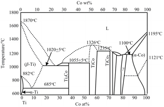
Figure 1.
Phase diagram of Ti-Co alloy [17,18].
Table 3.
Solubility of Co in Ti at different temperatures.
When the dissolution–diffusion phenomenon occurs in the cutting process, the hardness of the tool material reduces, resulting in an insufficient anti-wear damage performance of the tool. This is turn results in the premature failure of the tool. By analyzing the dissolution–diffusion mechanism in cutting, the anti-wear damage performance of the tool can be effectively improved. We demonstrate that the solubility of the WC grain and Co element in titanium alloy increases with the increase of temperature, and the diffusion capacity of the Co element is better than that of the WC grain.
2.3. Solubility Calculation of Coating Materials in Titanium
In order to improve a tool’s performance, it is necessary to carry out coating treatment on its surface. In the cutting process, the coating elements are first to come into contact with the processed material. With the extension of the processing time, the coating is peeled off, exposing the cemented carbide substrate; the cemented carbide material will then participate in the cutting. The coating materials studied in this paper are mainly Si and Zr element. Firstly, the diffusion between the Si element and Ti element is analyzed, and Si atoms react with Ti to produce Ti–Si compounds at the interface. From a thermodynamic perspective, these four Ti–Si compounds can be formed spontaneously [19], as shown in Table 4.
Table 4.
The free energy of Si at different temperatures.
In the temperature range of 953 K to 1053 K, the reaction in Table 4 can be spontaneous to produce Ti–Si binary compounds. Comparing the data in Table 4 and Table 1 demonstrates that at the same temperature, the free energy generated by the Si element is much lower than that of the WC grain. If the free energy is too low, this will lead to a reduction in solubility, and the Si element can then effectively prevent the dissolution and diffusion of Ti–Si during processing.
According to the research of Bhanumurthy and Kirkendall [20], the interface and displacement degree with the original interface, elemental dissolution and diffusion occur between Zr and Ti under the condition of 1173 K. They also found that the solubility of Zr in Ti is 1.41 × 10⁻¹¹%, which is much lower than the solubility of WC in Ti. It can therefore effectively prevent the dissolution and diffusion of Ti–Zr compounds.
3. Experimental Introduction
3.1. Coating Experiment
The main targets used in this study were TiAl alloy, TiSi alloy and Zr. Among them, the TiAl alloy and Zr targets were prepared via a vacuum melting process with a purity of 99.9%, while the TiSi alloy target was prepared via a crystal growth process with a purity of 99.99%. The target used in the experiment was a circular target with a diameter of 160 mm and was cooled by water circulation.
The endmill used in this study was the WC-Co-0.1Re cemented carbide produced by Jiangsu Tiangong Cemented Carbide Technology Co., Ltd., Danyang, China. According to the testing requirements, the substrate was cut by 12 mm and 6 mm diameter round rods, and the finished size was 12 mm × 2 mm and 6 mm × 5 mm. The substrate was mechanically ground and polished before coating. The substrate was also cleaned for 5 min in an ultrasonic cleaning machine containing ethanol.
In this experiment, the INNOVENTA Kila coating furnace made by Oerlikon group, Zurich, Switzerland was used to prepare the tool coating using the multi-arc ion plating method. The coating furnace could install 4 groups of 160 mm diameter targets at the same time, with 2 pieces in each group and 8 sets of arc power supplies, and 8 targets could work together. The sample loading position and turntable speed were adjustable, and the sample could rotate while the turntable rotated to ensure the uniformity of the coated film. Using a heating tube and plasma heating, the maximum operating temperature with this furnace can reach 800 °C.
The principles of multi-arc ion coating are shown in Figure 2, the internal structure of the coating experimental equipment is shown in Figure 2a and the basic principles of the coating experiment are shown in Figure 2b. The working process can be divided into five stages: vacuum-pumping, heating, etching, coating and cooling. Firstly, the cranial cavity of the coating furnace was vacuumed by a three-stage vacuum pump, including a first-stage rotary vane pump and the pre-stage pump of a two-stage roots pump. The front pump pumps pressure from atmospheric pressure to 0.1 mbar. The three-stage pump adopts a molecular pump, which uses high-speed rotating turbine blades to continuously exert directional momentum and compression on the extracted gas molecules to expel the gas, and its working pressure needs to be lower than 0.1 mbar pre-pressure. The coating process requires a vacuum degree of 10−4 mbar, which can ensure the stability of the coating. Subsequently, the cranial cavity is heated with electric tubes and plasma. The heating of the electric tubes is mainly carried out by the thermal effect of resistance principle, and the heaters are evenly distributed in the upper or lower part of each arc source. When the plasma is heated, a high-intensity current is passed into the filament in the ion chamber, and the hot electron ionization excited by the filament is passed into the argon gas in the ion chamber to form a plasma beam. The electron beam moves down at a high speed under the attraction of the anode of the workpiece, exciting the hydrogen in the reaction chamber. This causes a large number of particles to impact the surface of the workpiece, and the ionization, impact, recombination and annihilation of high-density particles generate a large amount of heat. Then, etching is carried out. Argon plasma is formed by ionizing argon gas. The positively charged argon ions in the plasma accelerate in the electric field generated by the biased power supply and impact the substrate of the tool at a high speed to remove the oxide layer on the surface of the substrate and increase the binding force of the coating. Finally, entering the coating stage, the arc discharge is triggered by the arc triggering device, the evaporation source of the target is used as the cathode and the arc discharge is carried out under 10 KV pulse high voltage, so that the target evaporates and ionizes, forming a space plasma to deposit and coat the tool. After the coating is finished, the nitrogen valve is opened, and nitrogen fills the furnace to the set pressure of about 800 mbar. After the furnace body is cooled to 200 °C, the exhaust gas is released to finish the coating of the product.
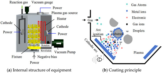
Figure 2.
Principles of multi-arc ion coating [21].
During the coating inspection, Premier made by Bruker group, Billerica, MA, USA was used to measure hardness and elastic modulus and RST300 made by Anton Paar group, Graz, Austria was used to detect scratches.
3.2. Milling Experiment
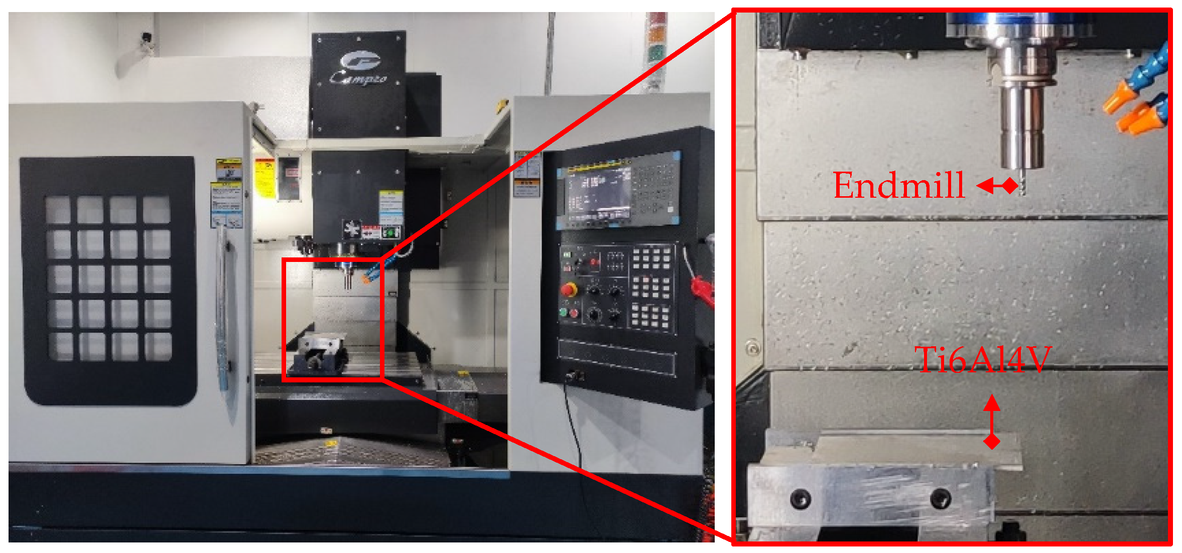
TiAlN/TiSiN and TiAlN/TiSiN/ZrN coated cemented carbide endmills were prepared. The geometric parameters of the endmills are shown in Table 5. The milling experiment is shown in Figure 3. The milling experiment was carried out using a CAMPIOCNV-900 high-speed machine made by Campio Precision Machinery Co., Ltd., Shanghai, China and water-based emulsion was used for cooling. The ratio of cutting fluid to water was 1:6. Milling experimental parameters are shown in Table 6.
Table 5.
Geometric parameters of the endmills.

Figure 3.
Milling experiment.
Table 6.
Milling experimental parameters.
4. Results and Discussion
4.1. Base Structure and Morphology
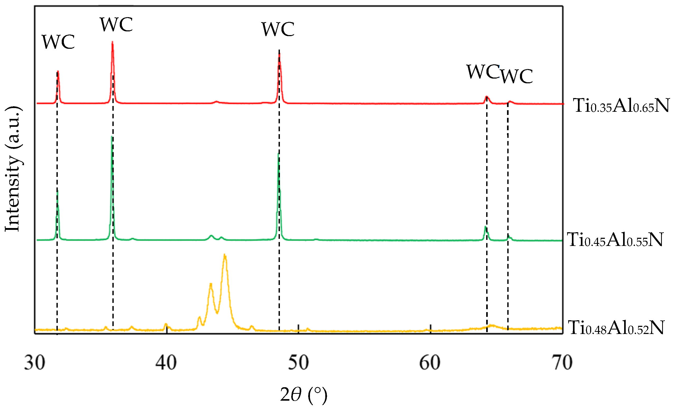
TiAlN coatings with different Al content were prepared by using Ti:Al atomic ratios of 60:40, 50:50 and 40:60 targets, respectively. The EDS results showed that the coatings were Ti0.48Al0.52N, Ti0.45Al0.55N and Ti0.35Al0.65N, respectively. It can be seen that the content of Al in the coating is slightly higher than in the target, because when the target was bombarded by an arc, the high temperature caused the evaporation of the Al and Ti elements. The melting point of Al was lower than Ti, resulting in the evaporation rate of Ti being slightly lower than that of Al. The XRD of TiAlN coating with different contents is shown in Figure 4.
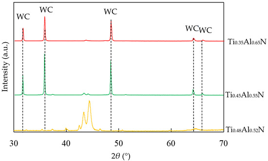
Figure 4.
XRD of TiAlN coating with different contents.
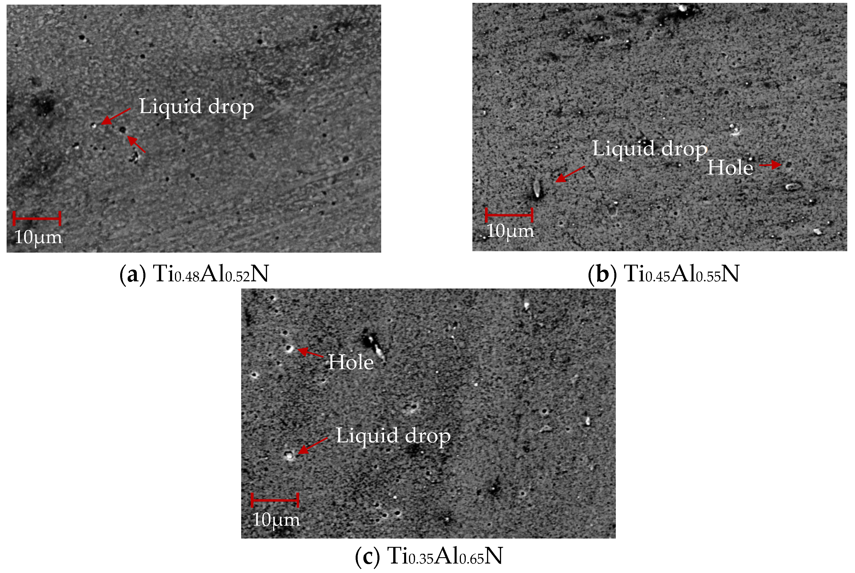
The SEM morphology of TiAlN coatings with different content is shown in Figure 5. It can be seen that with the increase of Al content, the particles on the surface of the coating became larger and the density decreased. The shape of the particles also changed from dense particles to large particles. The reason for this change in particle shape is mainly because the hexagonal AlN structure generated in the coating process changes the phase composition and grain orientation. With the increase of Al content, droplets and pores increase significantly, which will affect the coating quality.
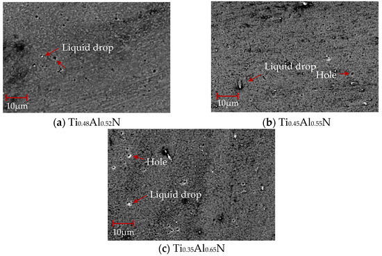
Figure 5.
SEM morphology of TiAlN coatings with different content.
Roughness is an important factor affecting the performance of tool coatings. Too much roughness will lead to an increase in cutting force and cutting temperature, accelerate tool wear, and reduce tool life and workpiece processing quality. As the base layer acts as a transition layer between the functional layer and the substrate layer, surface roughness affects the binding force and performance of the coating. The surface morphology of TiAlN coating with different content is shown in Figure 6. Surface roughness increases with the increase of Al content. When the atomic percentage of Al is 52%, the surface roughness is the lowest, at about 0.123 μm, and with the increase of Al content, the surface roughness increases rapidly. When the atomic percentage of Al element reaches 55%, the surface roughness is close to 0.15 μm. The change of surface roughness is not obvious when the atomic percentage of Al element is 65%; the surface roughness increases by only 0.004 μm to 0.154 μm.
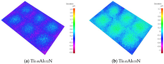
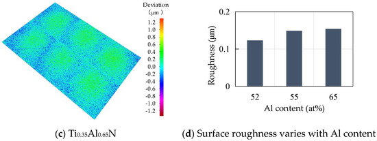
Figure 6.
Surface morphology of TiAlN coatings with different content.
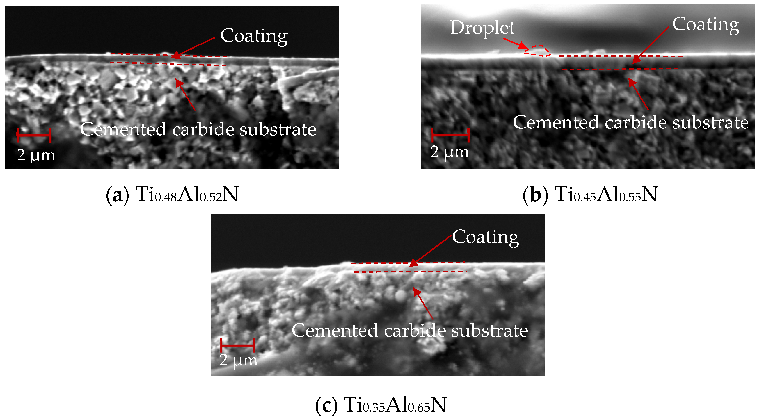
The cross-section morphology of TiAlN coating with different content is shown in Figure 7, and the bottom is the WC–Co cemented carbide substrate with a coating thickness of about 1 μm. As shown in Figure 7a, TiAlN coating has an non-dense columnar or fibrous structure. Compared with Figure 7b and Figure 7c, the columnar or fibrous structure weakens significantly with the increase of Al content. This is due to the increase of AlN content in the hexagonal wurtzite structure.
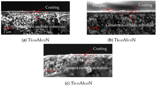
Figure 7.
Cross-section morphology of TiAlN coatings with different content.
4.2. Mechanical Properties of Base Layer
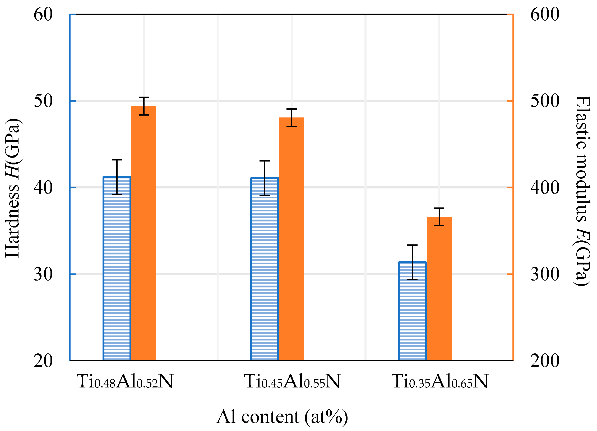
The hardness and elastic modulus of the coating were measured using a nanoindentation instrument. The results are shown in Figure 8. It can be seen that the hardness of the TiAlN coating decreased with the increase of Al content. The hardness was approximately proportional to the decreasing rate of the elastic modulus. When the Al atomic ratio content was at its highest, at 65%, the hardness value of the coating was at its lowest, at about 31.36 GPa. This is mainly because the excessive content of Al element and N element combine at a high temperature to form a hexagonal AlN binary compound with low hardness. This relatively low hardness of the base coating will lead to a decline in the overall hardness of the coating.
Figure 8.
Hardness and elastic modulus of TiAlN coatings with different content.
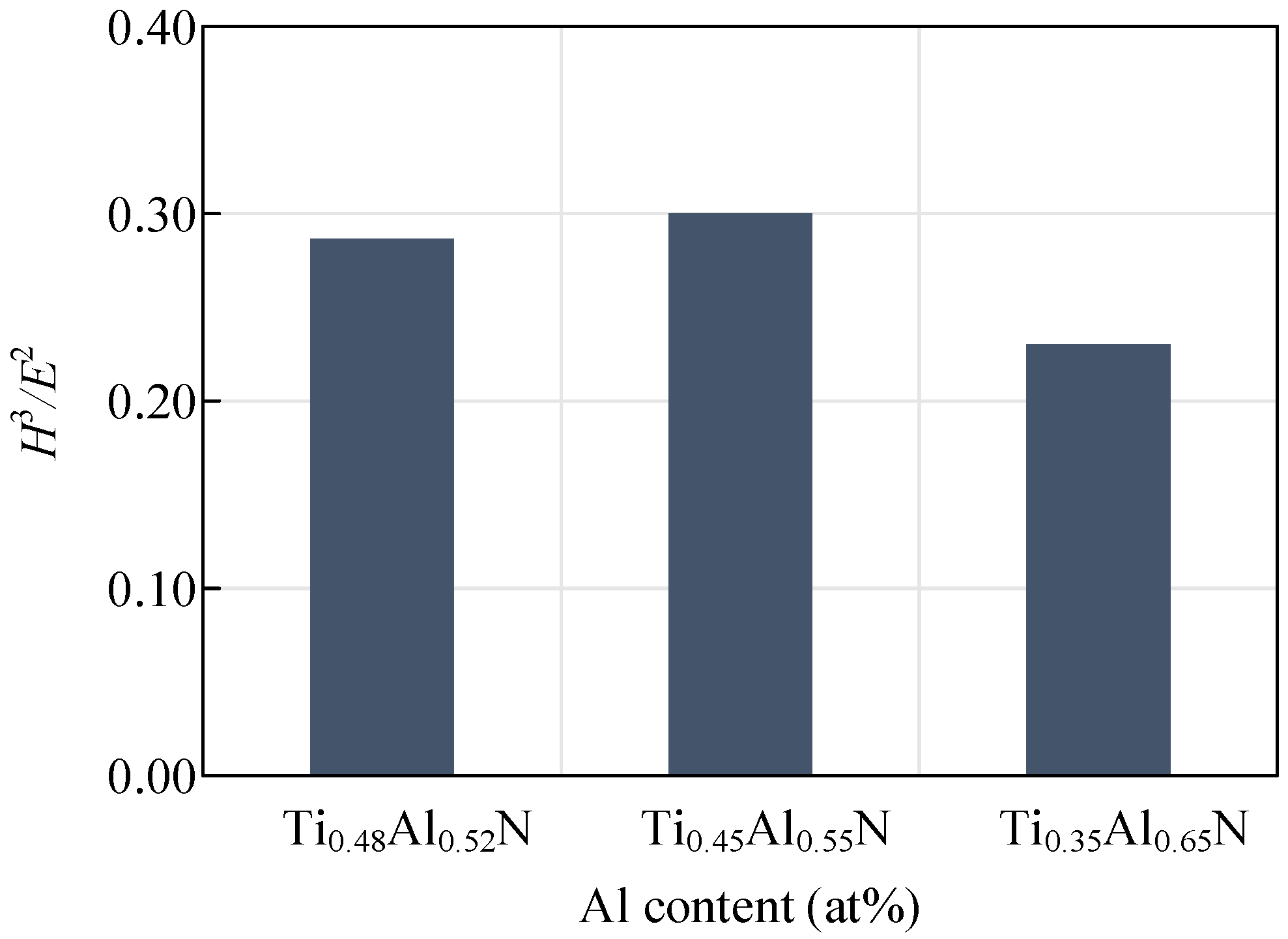
The hardness and elastic modulus of the coating can reveal the wear resistance of the tool, which is generally expressed by H3/E2. The wear resistance of the coating increases with the increase of the H3/E2 value. Figure 9 shows the change curve of the H3/E2 value of coatings with different Al content. With the decrease of Al content, H3/E2 values first increased and then decreased. A coating with a small elastic modulus can tolerate more elastic deformation before failing. The coating will last longer if more work completed by the outside world is absorbed. At the same time, when the elastic modulus of the coating and the substrate tends to be consistent, the binding strength of the coating and the substrate will be increased. It is known that the elastic modulus of the WC-Co-0.1Re carbide is about 600 GPa, and the Ti0.45Al0.55N substrate coating with a higher elastic modulus will give the tool higher wear resistance.

Figure 9.
Influence of coatings with different Al content on H3/E2 values.
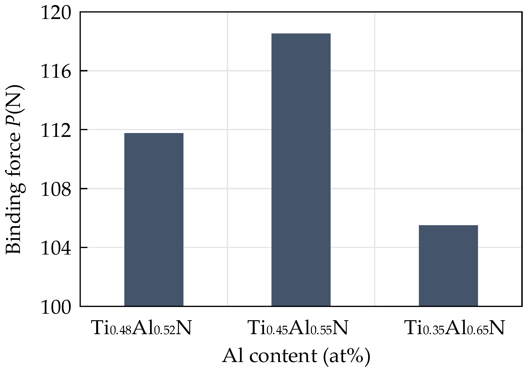
In addition to the hardness and the H3/E2 value, the binding force between the coating and the substrate is also an important parameter to reflect the performance of the coating tool. It is an important indicator of the excellent performance of the coating. Due to the difference in thermal expansion coefficient, elastic modulus and crystal structure between the coating and the substrate, the interface between the coating and the substrate will produce a large amount of stress. This will make the coating flake easily and fail under the action of stress in the cutting process. A scratch test was carried out on the surface of the coating with a scratch length of 3 mm and a linear termination load of 200 N. When the scratch entered the peeling area from the sliding area, the critical load applied was the binding force of the coating. The influence of different contents of TiAlN on the binding force of the coating is shown in Figure 10. The critical load increased first and then decreased with the increase of Al content. The results show that the binding force of the coating first increased and then decreased with the increase of Al content. When the Al atomic content was 55%, the binding force of the coating was at its highest, which was 118.53 N.
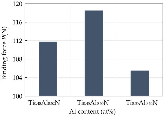
Figure 10.
Influence of different contents of TiAlN on coating binding force.
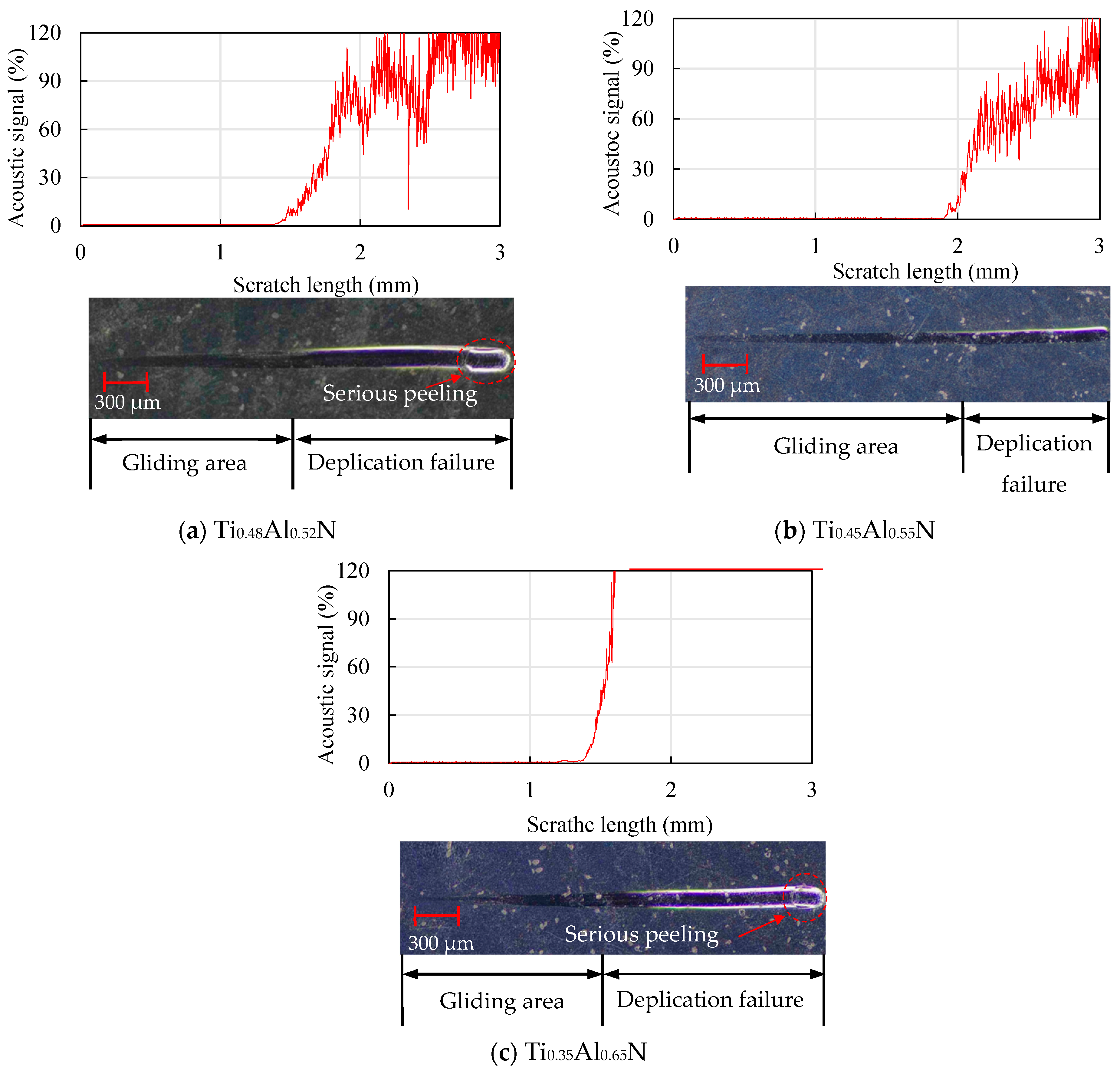
The scratch morphology of the TiAlN coatings with different content is shown in Figure 11. By observing the scratch morphology, it was found that the Ti0.45Al0.55N coating in Figure 11b had the longest sliding area, which was about 1.9 mm. The sliding area first increased and then decreased, and at the end of the scratch, an obvious peeling phenomenon could be observed.
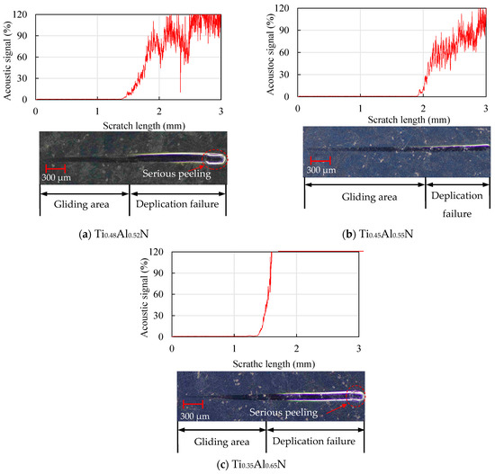
Figure 11.
Analysis of scratch morphology of TiAlN coatings with different content.
4.3. Structure and Morphology of Functional Layer
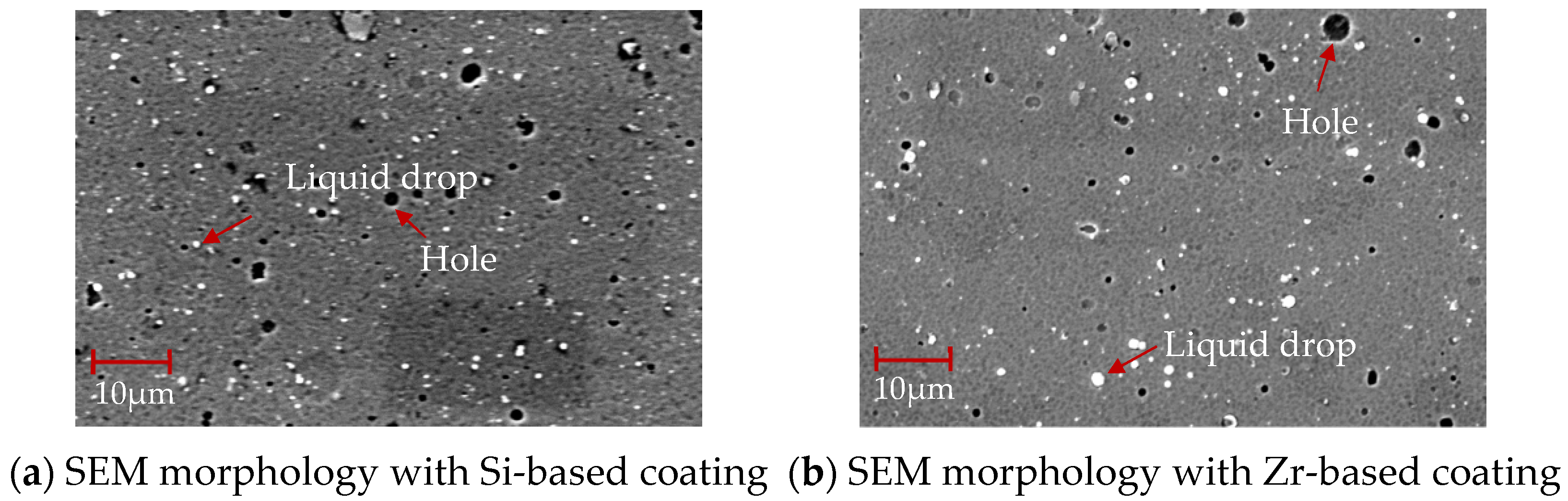
The SEM morphology of the coating surface of different functional layers is shown in Figure 12. There are droplets and pores on the coating surface. Compared with Figure 12a, the Zr-based coating in Figure 12b is denser. There are fewer surface pores and droplets, which is more conducive to the flow of chips through the rake face and ensures a high-quality performance of the coating.
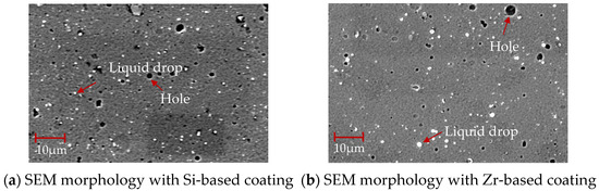
Figure 12.
SEM morphology of coatings with different functional layers.
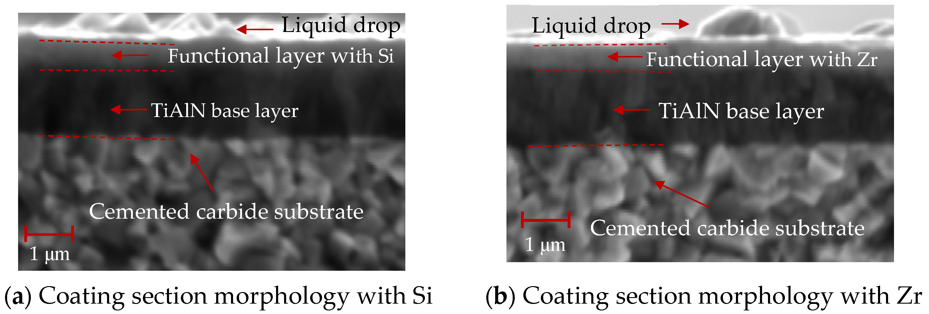
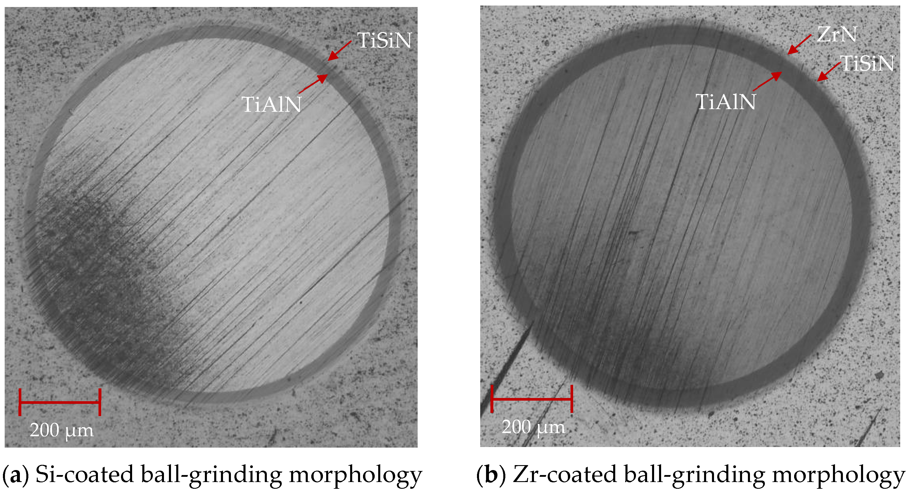
As shown in Figure 13, the cross-sectional SEM morphology of the coatings with different functional layers was found to contain droplets on the surface. The internal structure of the coating was observed. As is shown in Figure 13a, the cross-sectional morphology of the Si coating can be divided into three parts: the cemented carbide substrate, the base layer and the functional layer. The coatings of the base layer and functional layer are uniform and dense without pores. As shown in Figure 13b, the cross-sectional morphology of the Zr-based coating can be divided into four parts: the cemented carbide substrate, the base layer, the functional layer and the lubricating layer. A layer of ZrN coating is deposited on the surface of the Si-based coating. The coating has a dense morphology, no pores inside and a uniform film thickness. Figure 14 shows the ball-grinding morphology of coatings with different functional layers. As shown in Figure 14a, the thickness of TiAlN coating is about 1.27 μm, the thickness of TiSiN coating is about 0.77 μm and the total coating thickness is about 2.04 μm. Figure 14b shows the cross-sectional morphology of the Zr-based coating. The thickness of the TiAlN coating is about 1.71 μm, the thickness of the TiSiN/ZrN coating is about 1.04 μm and the total coating thickness is about 2.75 μm. The thicknesses of the Si- and Zr-based coatings are similar. The cross-sectional morphology of the coating is good and the film thickness is uniform.
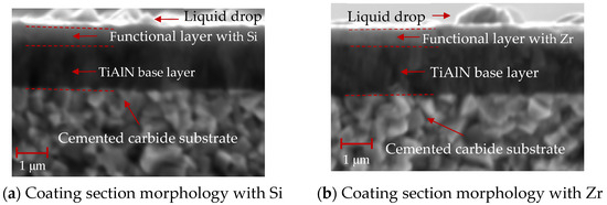
Figure 13.
SEM profiles of different functional layers.
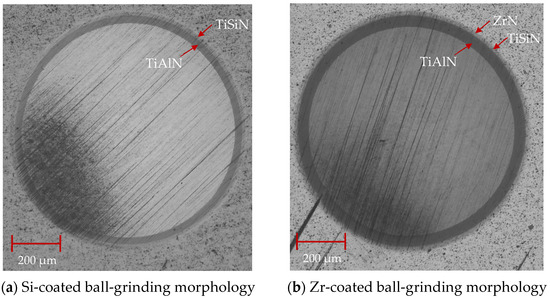
Figure 14.
Ball-grinding morphology of different functional layer coatings.
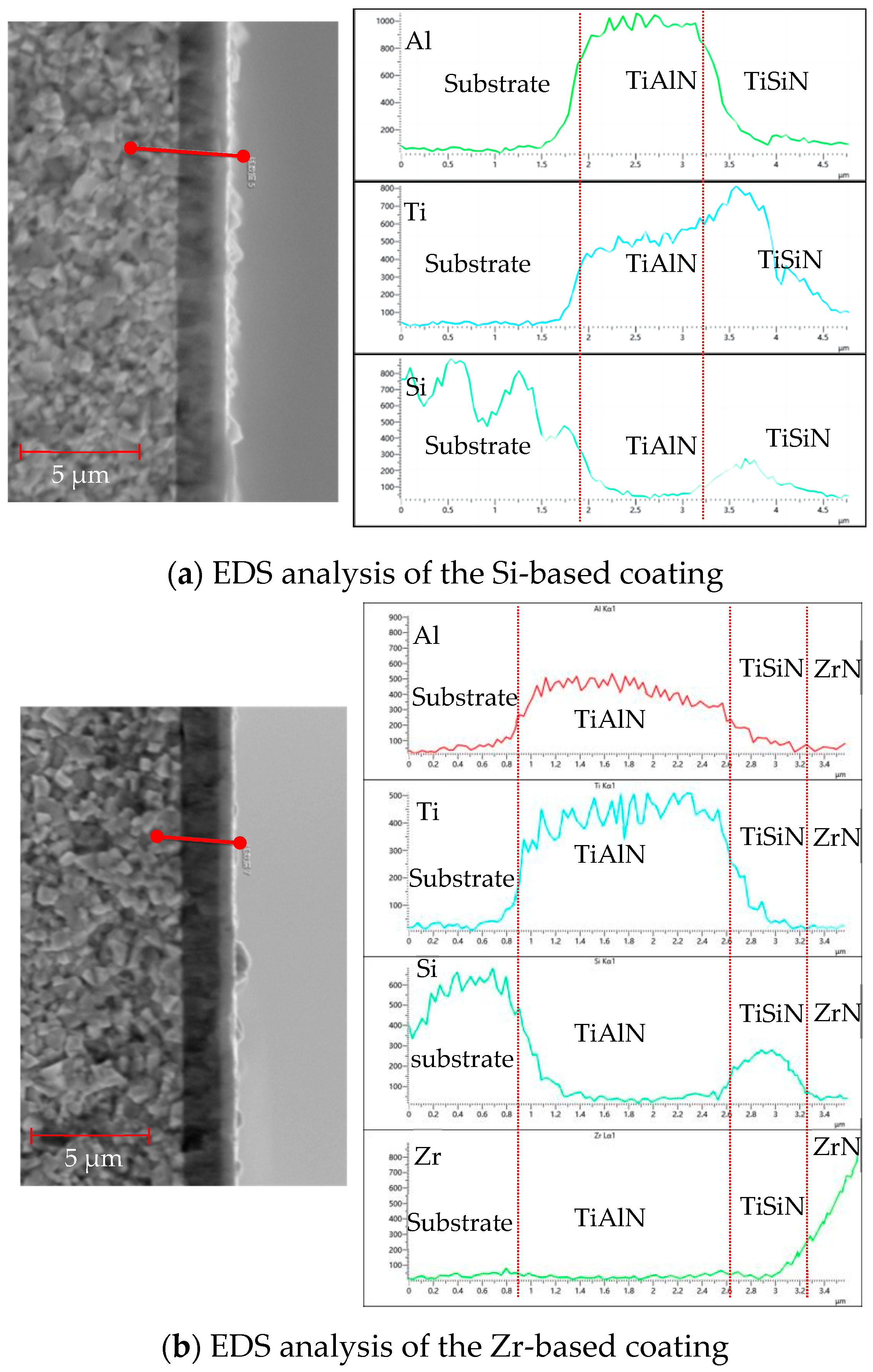
Figure 15 shows the EDS analysis of the cross-sections of different functional layers. As shown in Figure 15a, the EDS analysis of the Si-based coating shows that, at a distance of 1.5 μm, the Al element content increased and the base coating started to deposit at 3.2 μm. The content of Al elements decreased, the deposition of the functional layer began, and the content of Si and Ti elements increased. The increase observed in the content of the W element should be due to the Si element, because the electron energy peak of Si is close to W and cannot be accurately identified. To observe the ball-grinding morphology of the Si coating, please refer to Figure 14. As shown in Figure 15b, the EDS analysis of the Zr-based coating shows that, at 0.8 μm, the Al element content increased and the base layer coating began to be deposited. At 2.6 μm, the Al element content decreased and the deposition of the functional layer began; the Si element content also increased and the TiSiN functional layer was deposited. When the deposition reached 3.2 μm, the Zr element content began to increase and the ZrN coating was performed. The deposition was completed when the deposition reached about 3.5 μm.
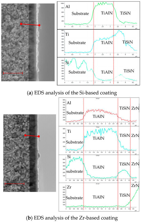
Figure 15.
EDS analysis of cross sections of different functional layers.
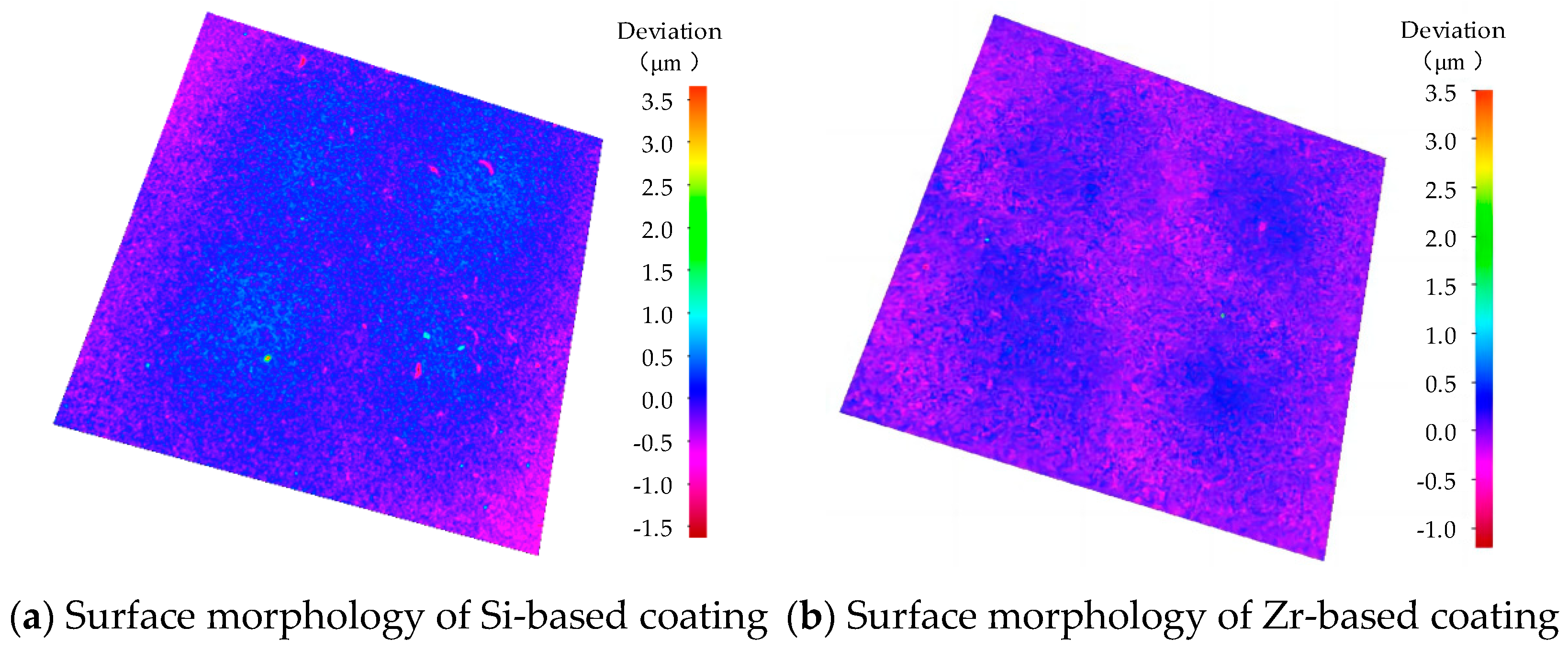
The surface morphology of different functional layers is shown in Figure 16. As shown in Figure 16a, the surface roughness of the coating was 0.186 μm. As shown in Figure 16b, the surface roughness of the coating was 0.129 μm. With the addition of Zr, the surface quality of the coating was improved and the surface roughness was reduced. A coating surface with lower roughness is more conducive to the flow of chips through the rake face, delays heat transfer, reduces the friction heat generated by the friction between the chips and the rake face, hinders heat diffusion, improves the tool coating performance and extends the cutting life of the tool.
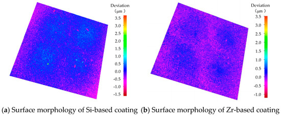
Figure 16.
Surface morphology of different functional layers.
4.4. Analysis of Mechanical Properties of Functional Layer
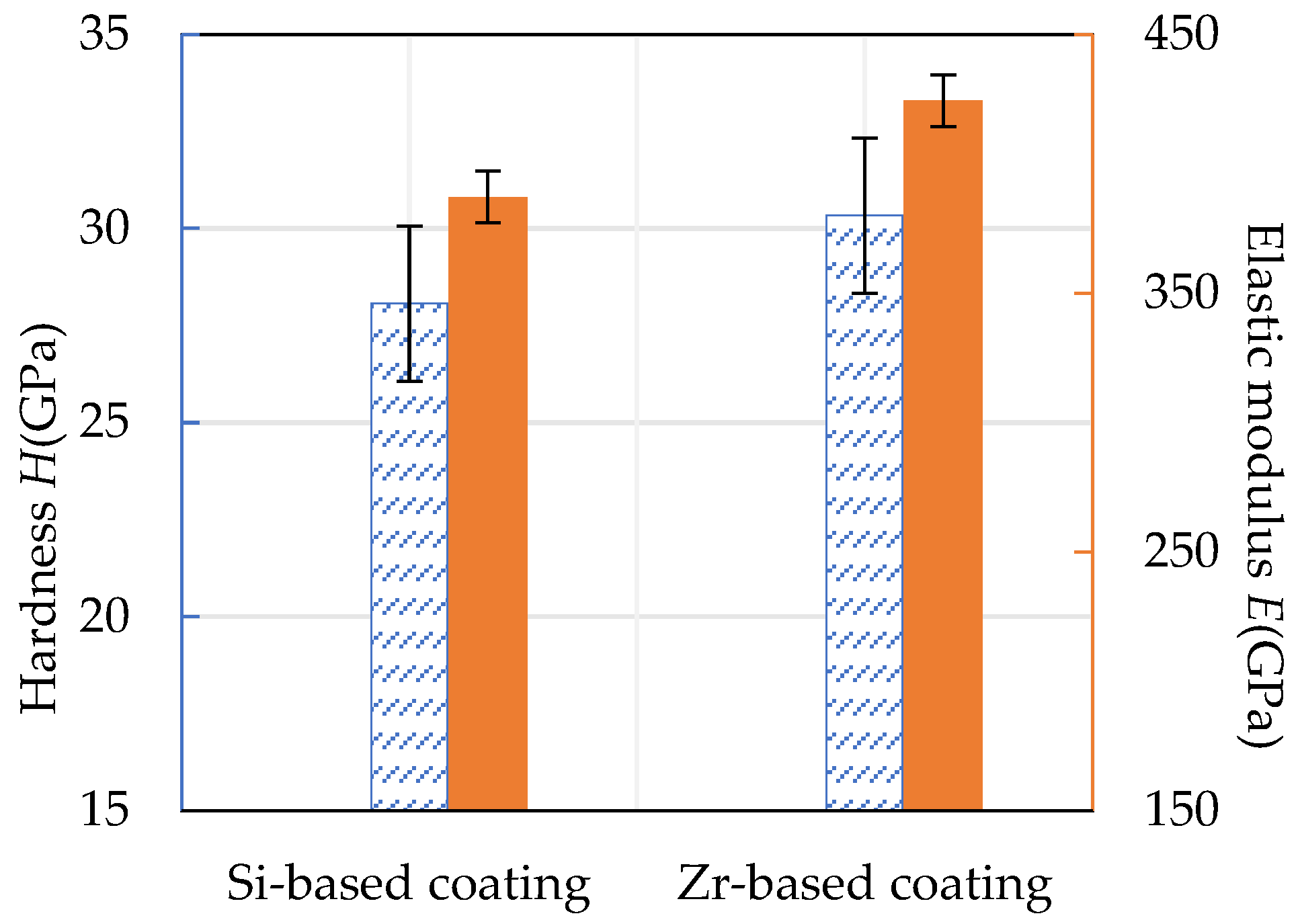
The hardness and elastic modulus of the Si-based coating and the Zr-based coating are shown in Figure 17. It can be seen that the hardness of the Si-based coating was about 28.07 GPa and the elastic modulus was about 384.17 GPa. The hardness of Zr-based coating was about 30.34 GPa and the elastic modulus was about 424.48 GPa. The addition of Zr improved the compactness of the Si-based coating, resulting in an increase in hardness by 8.09% and an increase in elastic modulus by 9.65%.
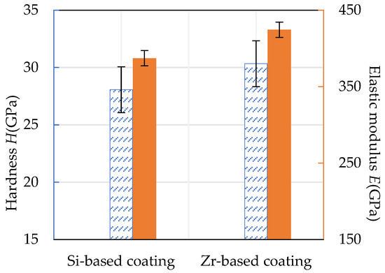
Figure 17.
Hardness and elastic modulus of Si-based coating and Zr-based coating.
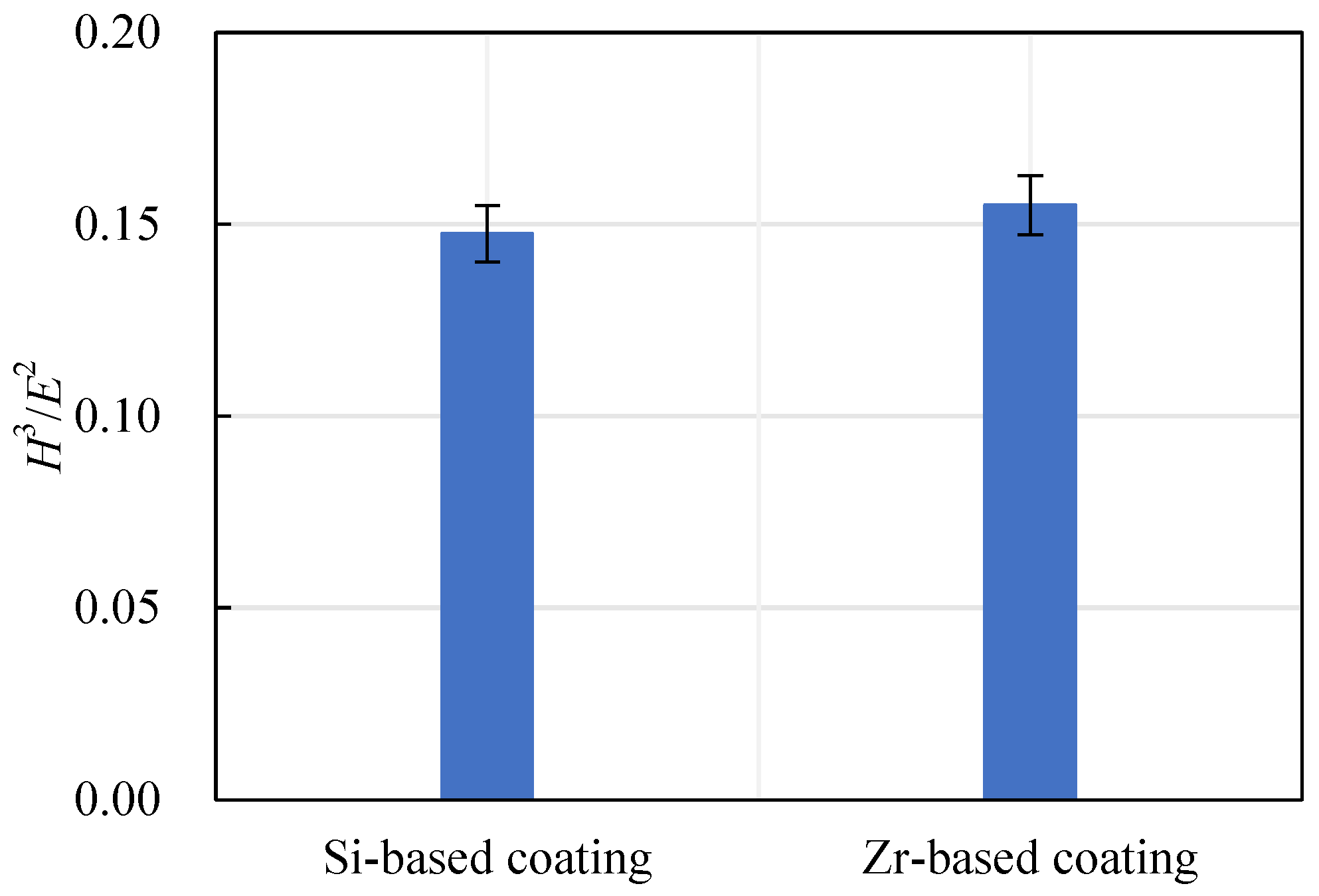
The ratio of hardness to elastic modulus reflects the wear resistance of a coating, expressed as H3/E2. The wear resistance of a coating increases with the increase of the H3/E2 ratio. The Si-based coating and the Zr-based coating H3/E2 are shown in Figure 18. With the addition of Zr element, the H3/E2 ratio increased from 0.15 to 0.16, indicating that the wear resistance of the coating had been further improved.
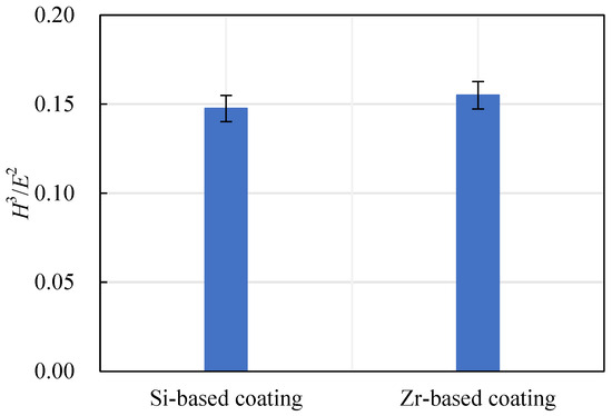
Figure 18.
Si-based coating and Zr-based coating H3/E2.
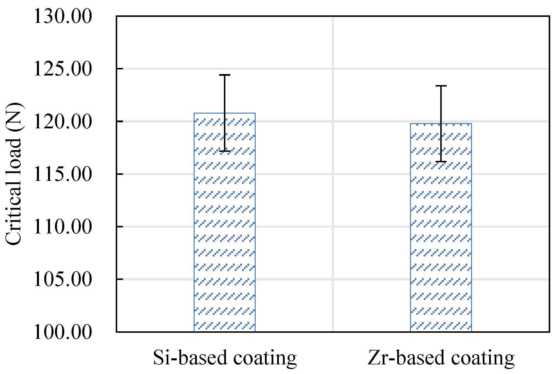
The critical load of the Si-based coating and the Zr-based coating is shown in Figure 19. The critical load indicates the bonding strength of a coating. It can be seen from this figure that the bonding strength of the Si-based coating and the Zr-based coating is equivalent. Among them, the Si-based coating was slightly larger than the Zr-based coating.
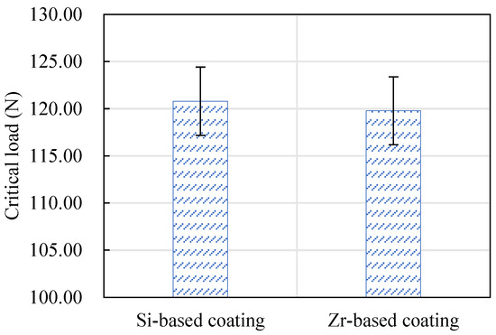
Figure 19.
The critical load values of Si-based coating and Zr-based coating.
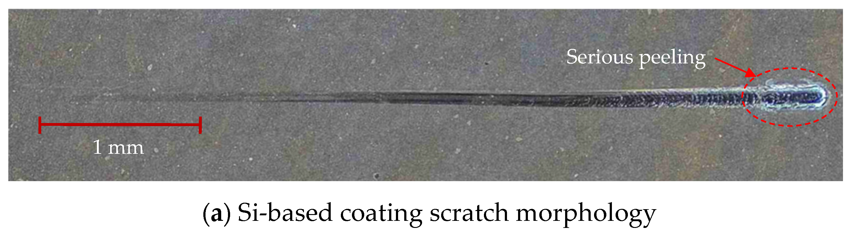
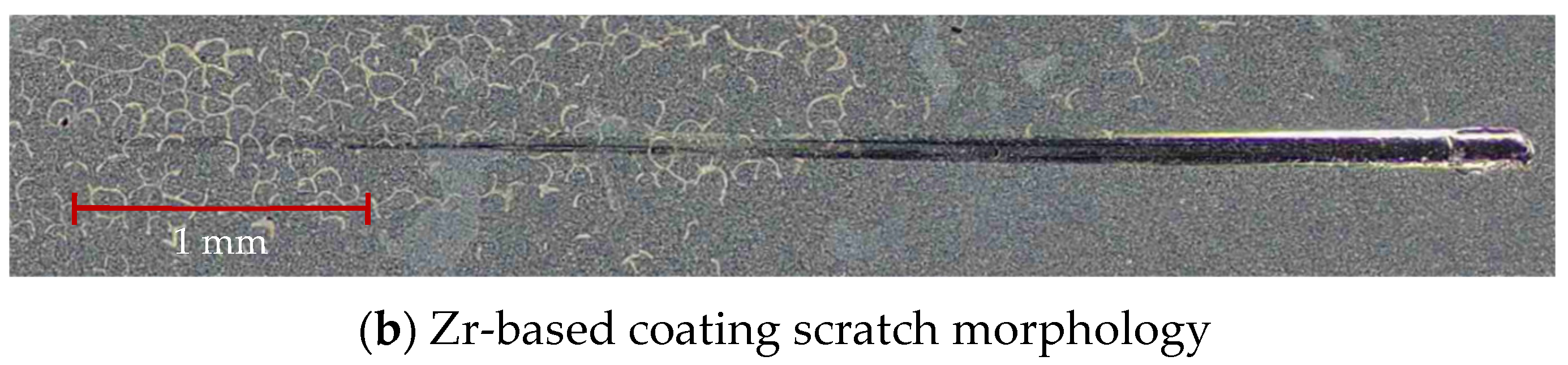
Figure 20 shows the scratch morphology of the coating after the bonding force test. The total length of the scratch was 5 mm, the loading speed was 100 N/m and the end load was 200 N. As can be seen from the figure, there was no obvious peeling during the entire loading process. The surface quality of the Si-based coating was good in the early stage of scratching. As the load continued to increase, the scratch morphology of the Si-based coating peeled off and showed cracks in the final stage. The scratch morphology of the Zr-based coating was good, indicating that the coating bonding strength was enhanced with the addition of Zr element.
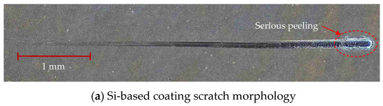
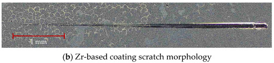
Figure 20.
Scratch morphology of Si-based coating and Zr-based coating.
4.5. Mechanical Property Analysis of Functional Layer
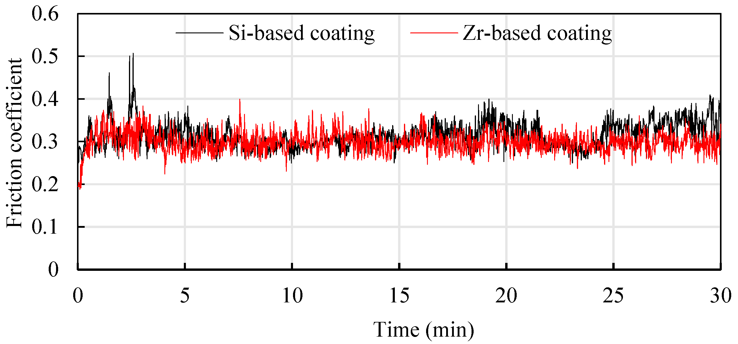
In order to study the friction reduction mechanism between Si and Zr functional layers and titanium alloys, titanium alloy friction tests were conducted on coatings with different compositions [22]. Ti6Al4V balls with a diameter of 5 mm were used to rub back and forth on the coating surface at a friction speed of 240 mm/min. The friction pressure was 10 N and the friction time was about 30 min. The results are shown in Figure 21. It can be seen that in the early stage of friction testing, the friction coefficient fluctuated greatly, which was mainly affected by the surface quality of the coating. As the friction time increased, it entered a stable stage. The average friction coefficient of the Si-based coating was 0.315, and the average friction coefficient of the Zr-based coating was about 0.299. The friction coefficient of the Zr-based coating was better than the Si-based coating. This is mainly because adding Zr element to the Si-based coating can improve the density of the coating and reduce the roughness of the coating surface, which is beneficial to the reduction of titanium alloy. The cutting force during cutting reduces the cutting heat generated caused by friction, protects the tool and extends the cutting life.
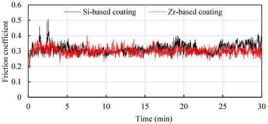
Figure 21.
Anti-wear mechanism of different functional layers.
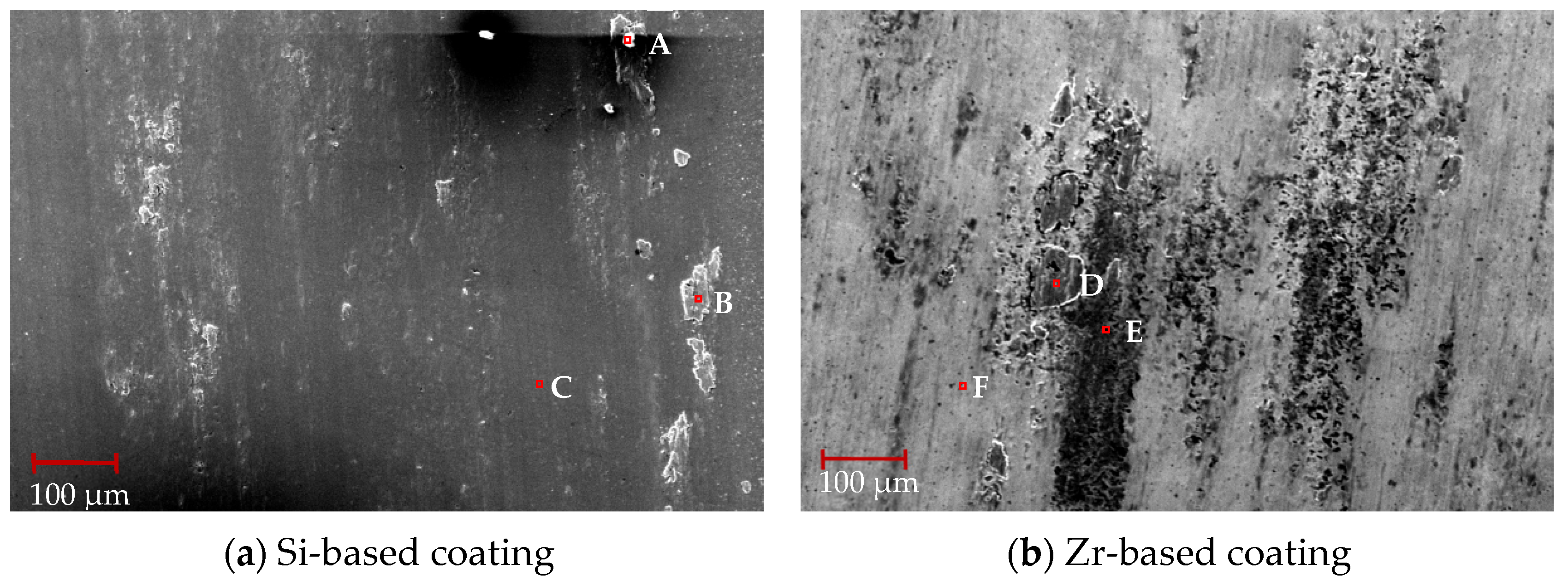
SEM was used to observe the surface wear scar morphology after friction and wear between the Si-based coating, Zr-based coating and titanium alloy. The results are shown in Figure 22. From Figure 22a, it can be seen that the Si-based coating surface bonding is obvious, and the main bonding areas are on the left and right sides of the friction area. Compared with Figure 22b, although the Zr-based coating has a lower friction coefficient, the coating obviously peels off and the peeling phenomenon is serious. This is due to the lubricating effect of the Zr element and the low hardness of the Zr-based coating. Peeling occurs during reciprocating friction.
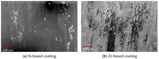
Figure 22.
Morphology of wear marks of different functional layers.
EDS composition analysis was performed on the coating surface. The results are shown in Table 7. Observing points A, point B and point D, it can be seen that the adhesive was mainly composed of Ti and O elements. The increase of Ti element indicates that two coating materials were both bonded with titanium alloy. Observing point C, it can be seen that the coating ingredients were intact and no bonding or peeling occured. Comparing with points F and E, it can be seen that the Zr element content was small and Si element appeared, which indicates that the coating surface with Zr element peeled off, exposing the harder Si element layer inside.
Table 7.
EDS analysis results of different component coatings after friction and wear test (at %).
4.6. Analysis of Flank Wear in Milling Ti6Al4V with Different Coatings
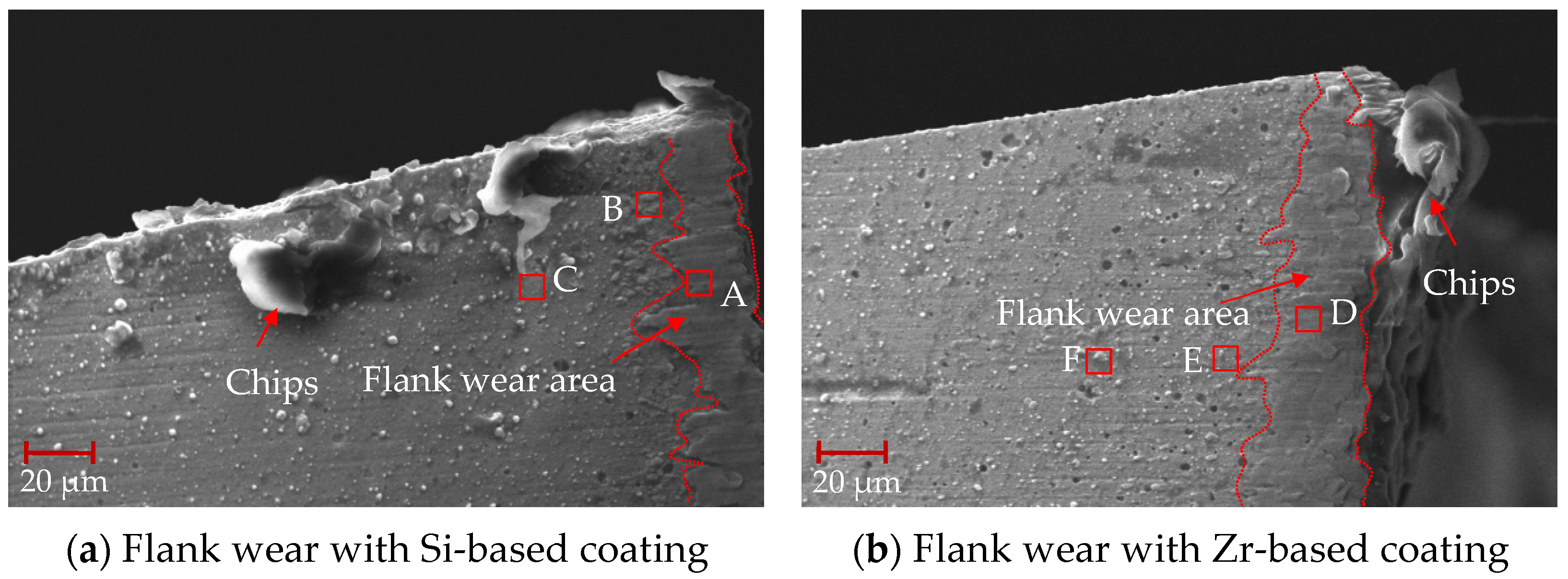
After machining for 0.5 min, the tool surface was treated with air blowing, and the initial flank wear of the milling process was analyzed, as shown in Figure 23. From this figure, it can be seen that there were some large particles of chips at the tool tip, and the flank wear area with coating was in good condition. Friction occured between the flank coating and the machined surface. The surface morphology of the coating changed, droplets and pores disappeared and the coating surface became smooth.
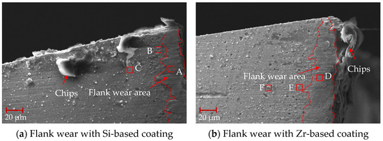
Figure 23.
Flank wear at the beginning of milling.
A surface scan was performed on the flank wear area, and the EDS analysis of coatings with different compositions after 0.5 min of processing is shown in Table 8. The analysis of point A revealed the existence of a small amount of V element. The V element mainly comes from Ti6Al4V, indicating that Ti6Al4V combines with the Si coating to form a smooth flank wear area. The analysis of point D found that a small amount of Si element existed, which shows that during the process, the Zr element in the TiSiN/ZrN coating slipped off and the Si element was exposed, ensuring the hardness and wear resistance of the tool coating. When comparing point D with points E and F, it can been seen that the content of Ti element increased significantly. This indicates that the Ti element had diffused into the Zr-based coating. The occurrence of element diffusion will lead to a reduction in the hardness of the coating and reduce the performance of the tool coating.
Table 8.
EDS analysis results of different component coatings after 0.5 min processing (at %).
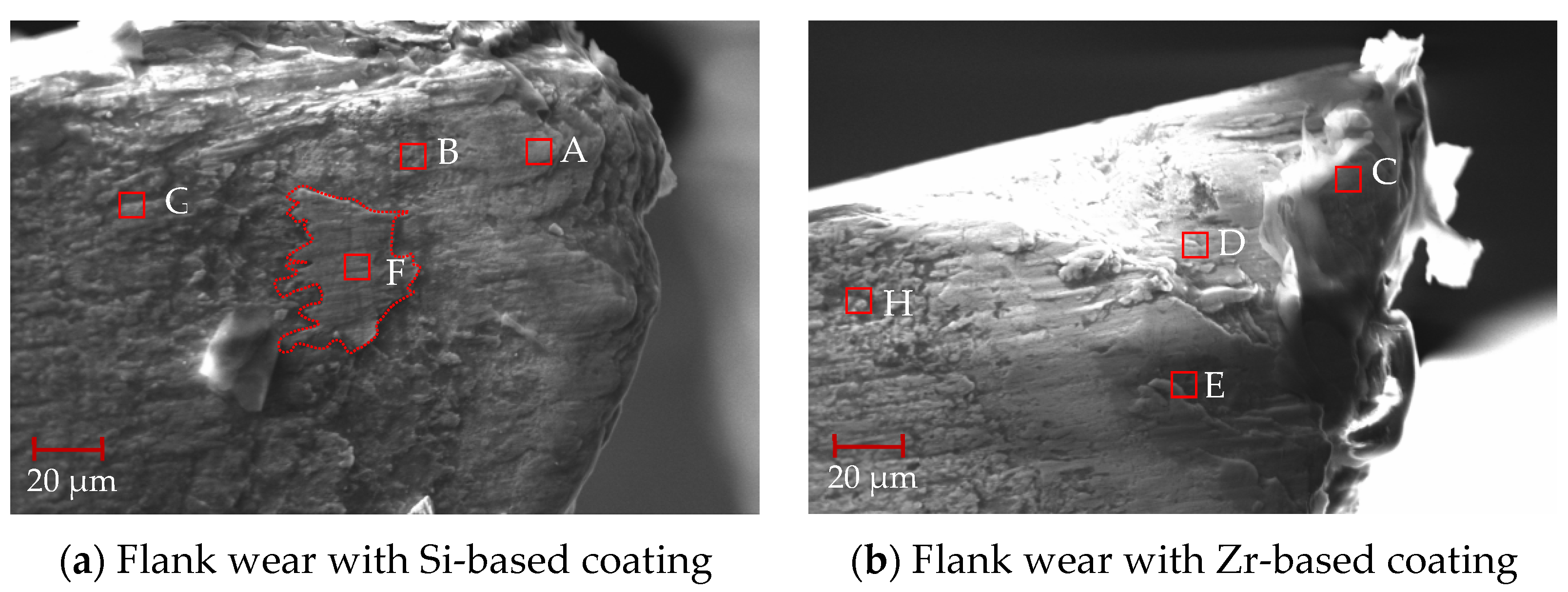
After 88 min of processing, the mid-term flank wear of the milling process was analyzed, as shown in Figure 24. From this figure, it can be seen that the flank surface was obviously stratified, and there were some chips at the tool tip. The EDS analysis was performed on different areas of the flank surface. As shown in Table 9, when comparing points A and C, it can be seen that the main element at the tool tip was Ti, and there was a small amount of V elements, indicating that adhesive wear occurred at the tool tip. However, there were small amounts of W and Co elements at point C. This shows that the bonding was weak and the cemented carbide substrate may have been exposed. The addition of ZrN coating delayed the occurrence of bonding wear. When comparing points B and D, elements V and W were detected at the same time, and element N was not detected, indicating that the hard metal substrate was exposed, the coating disappeared and element diffusion occurred between the substrate and the processed material. Analysis of point F shows that the main elements were Ti and V, indicating that this area was mainly bonded chips. Analysis of point E shows that there was also some Si elements in the Ti and V elements, indicating that the ZrN coating fell off and the TiSiN began to work. No large bonding area was found, indicating that ZrN effectively inhibited the occurrence of bonding phenomena during the cutting process. From points G and H, it can be seen that the presence of Si, Zr and N elements was detected, but no V element was detected, indicating the presence of the coating.

Figure 24.
Mid-term flank wear during milling.
Table 9.
EDS analysis results of different component coatings after 88 min processing (at %).
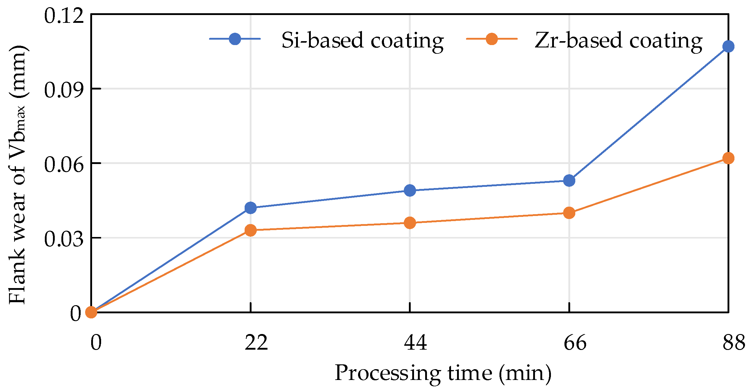
When Ti6Al4V was milled with cemented carbide endmills with different coatings, the flank wear value changed within the same period of time, as shown in Figure 25. Within 88 min, the overall coating was at a stable wear stage. For the Zr-coated flank surface, the wear value was smaller than that of the Si-based coating, indicating that the Zr-based coating had better wear resistance and was more conducive to improving the cutting life of the tool.
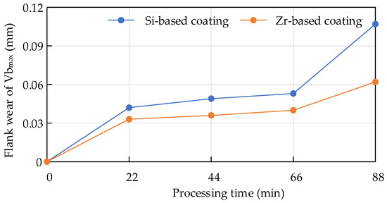
Figure 25.
Flank wear of endmills with different coatings during milling.
5. Conclusions
This article examined the coating for Ti6Al4V milling. First, the solubility between the coating elements of the functional layer and the Ti element was analyzed to verify the advantages of coating material performance. By designing the composition of the base layer and the functional layer, coatings with different compositions were obtained. The influences of elemental composition and elemental content on structure, morphology, mechanics and mechanical properties were then analyzed. Finally, the coating performance was assessed by grinding and milling tests. The main results were as follows:
- During the Ti6Al4V milling process, the occurrence of dissolution and diffusion phenomena were easily observed between the tool substrate and the processed material under high temperature conditions. This would reduce the wear and damage resistance of the tool. Based on thermodynamic solution theory, the dissolution and diffusion of Si and Zr in Ti at different temperatures were analyzed. The solubility of Si and Zr in Ti was found to be much lower than the solubility of W and Co, which can effectively prevent the occurrence of element diffusion.
- Research on base coatings with different Ti:Al ratios was conducted to obtain the proportion of Re-containing cemented carbide base coating elements. The surface roughness, hardness and elastic modulus of the base layer increased with the increase of Al element content. When the Ti:Al ratio was 50:50, there was a higher bonding force between the substrate and the base layer.
- The performance of the functional layers TiSiN and TiSiN/ZrN was analyzed. Compared with the TiSiN coating, the addition of Zr element to TiSiN/ZrN reduced the surface roughness and increased the density of the coating; the hardness and elastic modulus of the coating were also improved. Friction and wear experiments were conducted with Ti6Al4V and it was found that the Zr-based coating obtained a lower friction coefficient.
- In further testing, a tool was prepared for Ti6Al4V milling experiments and the initial and medium-term tool wear were analyzed. It was found that the addition of the Zr element effectively suppressed the occurrence of bonding wear and effectively extended the cutting life of the tool.
Author Contributions
Conceptualization, W.Z. and J.Z.; Writing—original draft, Z.F.; Writing—review & editing, M.L. All authors have read and agreed to the published version of the manuscript.
Funding
This research was funded by Jiangsu Tiangong Cemented Carbide Technology Co., Ltd.
Institutional Review Board Statement
Not applicable.
Informed Consent Statement
Not applicable.
Data Availability Statement
Data are contained within the article.
Conflicts of Interest
All authors were employed by the company Jiangsu Tiangong Cemented Carbide Technology Co., Ltd. The funder was not involved in the study design, collection, analysis, interpretation of data, the writing of this article or the decision to submit it for publication.
References
- Jawaid, A.; Sharif, S.; Koksal, S. Evaluation of wear mechanisms of coated carbide tools when face milling titanium alloy. J. Mater. Process. Technol. 2000, 99, 266–274. [Google Scholar] [CrossRef]
- Chim, Y.C.; Ding, X.Z.; Zeng, X.T.; Zhang, S. Oxidation resistance of TiN, CrN, TiAlN and CrAlN coatings deposited by lateral rotating cathode arc. Thin Solid Film. 2009, 517, 4845–4849. [Google Scholar] [CrossRef]
- Liu, A.; Deng, J.; Cui, H.; Chen, Y.; Zhao, J. Friction and wear properties of TiN, TiAlN, AlTiN and CrAlN PVD nitride coatings. Int. J. Refract. Met. Hard Mater. 2012, 31, 82–88. [Google Scholar]
- Chen, L.; Paulitsch, J.; Du, Y.; Mayrhofer, P.H. Thermal stability and oxidation resistance of Ti–Al–N coatings. Surf. Coat. Technol. 2012, 206, 2954–2960. [Google Scholar] [CrossRef] [PubMed]
- An, Q.; Chen, J.; Tao, Z.; Ming, W.; Chen, M. Experimental investigation on tool wear characteristics of PVD and CVD coatings during face milling of Ti6242S and Ti-555 titanium alloys. Int. J. Refract. Met. Hard Mater. 2020, 86, 105091. [Google Scholar] [CrossRef]
- Kuram, E. The effect of monolayer TiCN-, AlTiN-, TiAlN- and two layers TiCN + TiN- and AlTiN + TiN-coated cutting tools on tool wear, cutting force, surface roughness and chip morphology during high-speed milling of Ti6Al4V titanium alloy. Proc. Inst. Mech. Eng. Part B J. Eng. Manuf. 2018, 232, 1273–1286. [Google Scholar] [CrossRef]
- Yi, J.Y.; Chen, K.H.; Xu, Y.C.; Zhu, C.J. Performance of AlTiBN and AlTiTaN coatings during milling of titanium. Surf. Eng. 2019, 35, 501–506. [Google Scholar] [CrossRef]
- Niu, Q.; Chen, M.; Ming, W.; An, Q. Evaluation of the performance of coated carbide tools in face milling TC6 alloy under dry condition. Int. J. Adv. Manuf. Technol. 2013, 64, 623–631. [Google Scholar] [CrossRef]
- Biksa, A.; Yamamoto, K.; Dosbaeva, G.; Veldhuis, S.; Fox-Rabinovich, G.; Elfizy, A.; Wagg, T.; Shuster, L. Wear behavior of adaptive nano-multilayered AlTiN/MexN PVD coatings during machining of aerospace alloys. Tribol. Int. 2010, 43, 1491–1499. [Google Scholar] [CrossRef]
- Srinivasan, B.; Rao, M.S.R.; Rao, B.C. On the development of a dual-layered diamond-coated tool for the effective machining of titanium Ti-6Al-4V alloy. J. Phys. D Appl. Phys. 2016, 50, 015302. [Google Scholar] [CrossRef]
- Thepsonthi, T.; Özel, T. Experimental and finite element simulation based investigations on micro-milling Ti-6Al-4V titanium alloy: Effects of cBN coating on tool wear. J. Mater. Process. Technol. 2013, 213, 532–542. [Google Scholar] [CrossRef]
- Çalışkan, H.; Küçükköse, M. The effect of aCN/TiAlN coating on tool wear, cutting force, surface finish and chip morphology in face milling of Ti6Al4V superalloy. Int. J. Refract. Met. Hard Mater. 2015, 50, 304–312. [Google Scholar] [CrossRef]
- Volosova, M.A.; Fyodorov, S.V.; Opleshin, S.; Mosyanov, M. Wear resistance and titanium adhesion of cathodic arc deposited multi-component coatings for carbide end mills at the trochoidal milling of titanium alloy. Technologies 2020, 8, 38. [Google Scholar] [CrossRef]
- Li, M.; Yue, C.; Liu, X.; Zang, W.; Jiang, Z. Diffusion between Ti6Al4V and Cemented Carbide with Different Compositions. Metals 2023, 13, 240. [Google Scholar] [CrossRef]
- Zhang, Z.; Wang, Q.J.; Mo, W. Metallography and Heat Treatment of Titanium; Metallurgical Industry Press: Dongcheng, China, 2009. [Google Scholar]
- Fan, Y.H.; Hao, Z.P.; Zheng, M.L.; Sun, F.L.; Niu, S.L. Tool diffusion wear mechanism in high efficiency machining Ti6Al4V. Key Eng. Mater. 2014, 579, 3–7. [Google Scholar] [CrossRef]
- Wang, W.; Zhang, H.; Wang, Q.; Ma, Z.; Chen, L. Effects of carbide inhibitor on microstructures and mechanical properties of ultrafine grained carbide cement WC-2.5TiC-10Co. Chin. J. Mater. Res. 2016, 29, 881–888. [Google Scholar]
- Zhou, X.; Wang, K.; Li, C.; Wang, Q.; Wu, S.; Liu, J. Effect of ultrafine gradient cemented carbides substrate on the performance of coating tools for titanium alloy high speed cutting. Int. J. Refract. Met. Hard Mater. 2019, 84, 105024. [Google Scholar] [CrossRef]
- Liang, Y.J.; Che, Y.C. Inorganic Substances Thermodynamic Data Handbook; Northeastern University Press: Shenyang, China, 1994. (In Chinese) [Google Scholar]
- Bhanumurthy, K.; Laik, A.; Kale, G.B. Novel method of Evaluation of Diffusion coefficients in Ti-Zr system. In Defect and Diffusion Forum; Trans Tech Publications Ltd.: Bäch SZ, Switzerland, 2008; Volume 279, pp. 53–62. [Google Scholar]
- Zha, X. Mechanical and Cutting Properties of Bilayer and Nano-Multilayer. Ph.D. Thesis, Huaqiao University, Xiamen, China, 2020. [Google Scholar]
- Chien, H.H.; Ma, K.J.; Vattikuti, S.V.P.; Kuo, C.-H.; Huo, C.-B.; Chao, C.-L. Tribological behaviour of MoS2/Au coatings. Thin Solid Film. 2010, 518, 7532–7534. [Google Scholar] [CrossRef]


Disclaimer/Publisher’s Note: The statements, opinions and data contained in all publications are solely those of the individual author(s) and contributor(s) and not of MDPI and/or the editor(s). MDPI and/or the editor(s) disclaim responsibility for any injury to people or property resulting from any ideas, methods, instructions or products referred to in the content. |
© 2024 by the authors. Licensee MDPI, Basel, Switzerland. This article is an open access article distributed under the terms and conditions of the Creative Commons Attribution (CC BY) license (https://creativecommons.org/licenses/by/4.0/).