

Research on the Optimal Protection Parameters of Graphene Composite Conductive Coatings Combined with Impressed Current Cathodic Protection Technology in Marine Atmospheric Environments

 ,
,
Abstract
:1. Introduction
2. Experimental Part
2.1. Preparation of Coating Samples
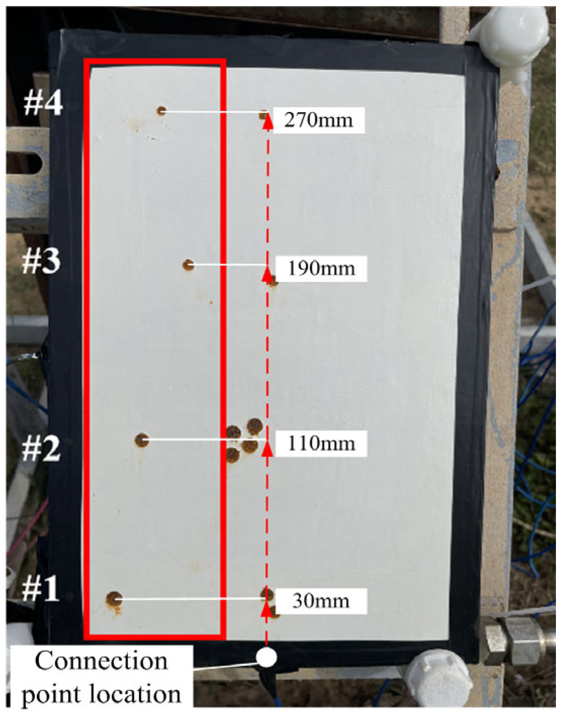
2.2. The Design of a Coating Combined with an Impressed Current Cathodic Protection System
2.3. Orthogonal Experimental Design
2.4. Marine Atmospheric Corrosion Exposure Test
2.5. Test and Characterization Methods
3. Results and Discussion
3.1. Orthogonal Experimental Results
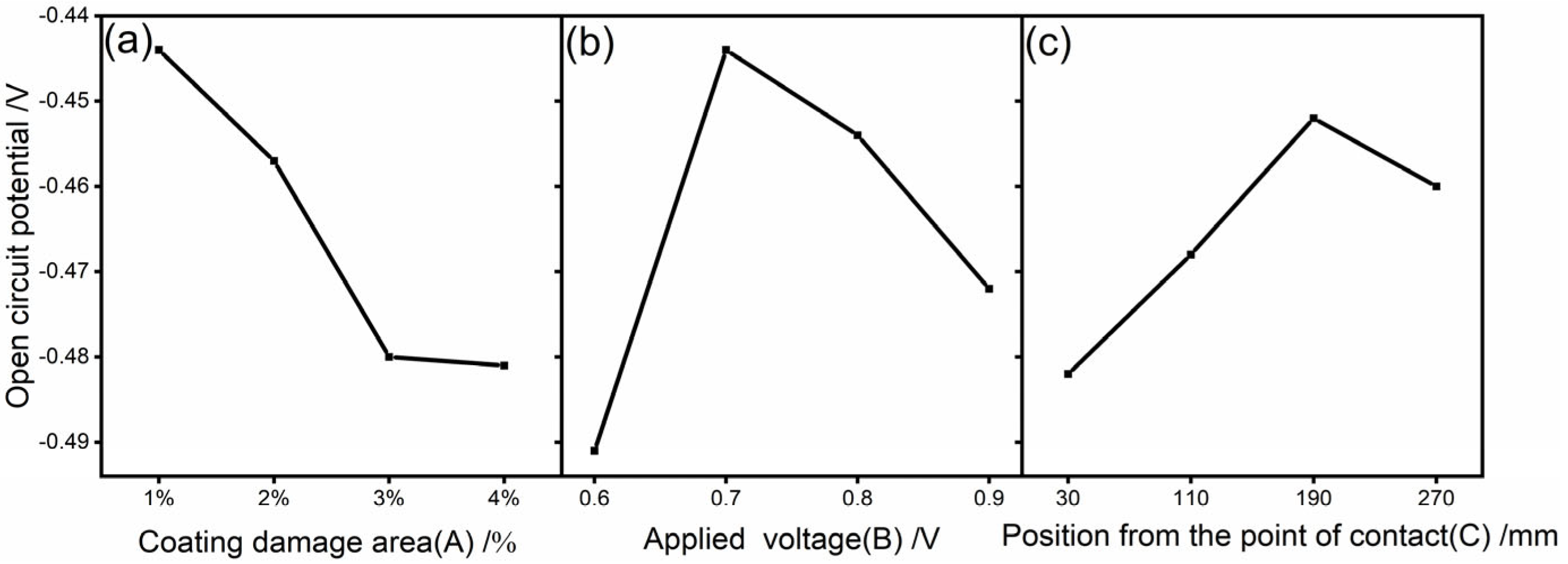
3.2. Range Analysis
4. Determination of the Optimal Protection Voltage and Effective Protection Distance of the Coating
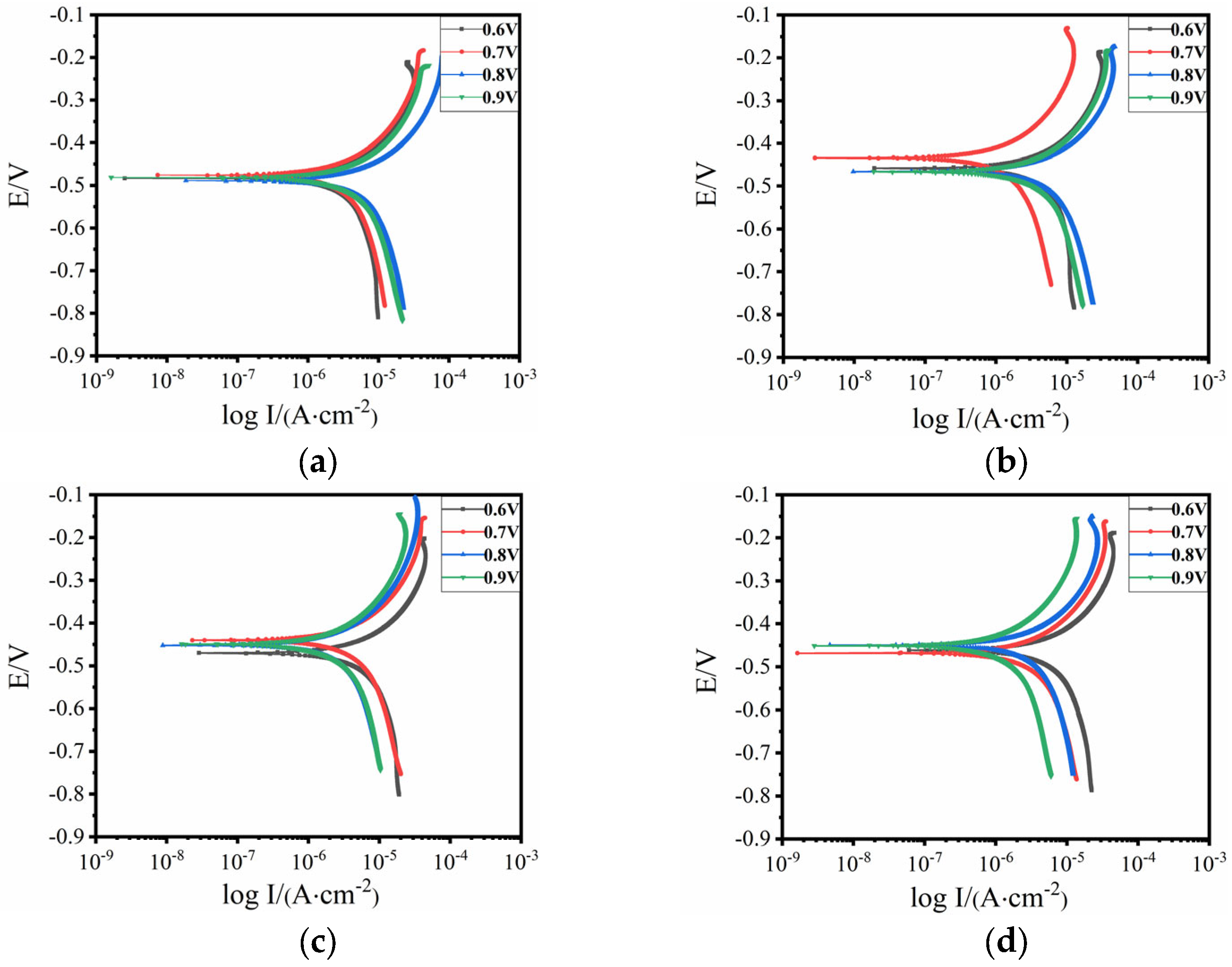
4.1. Optimal Protection Voltage
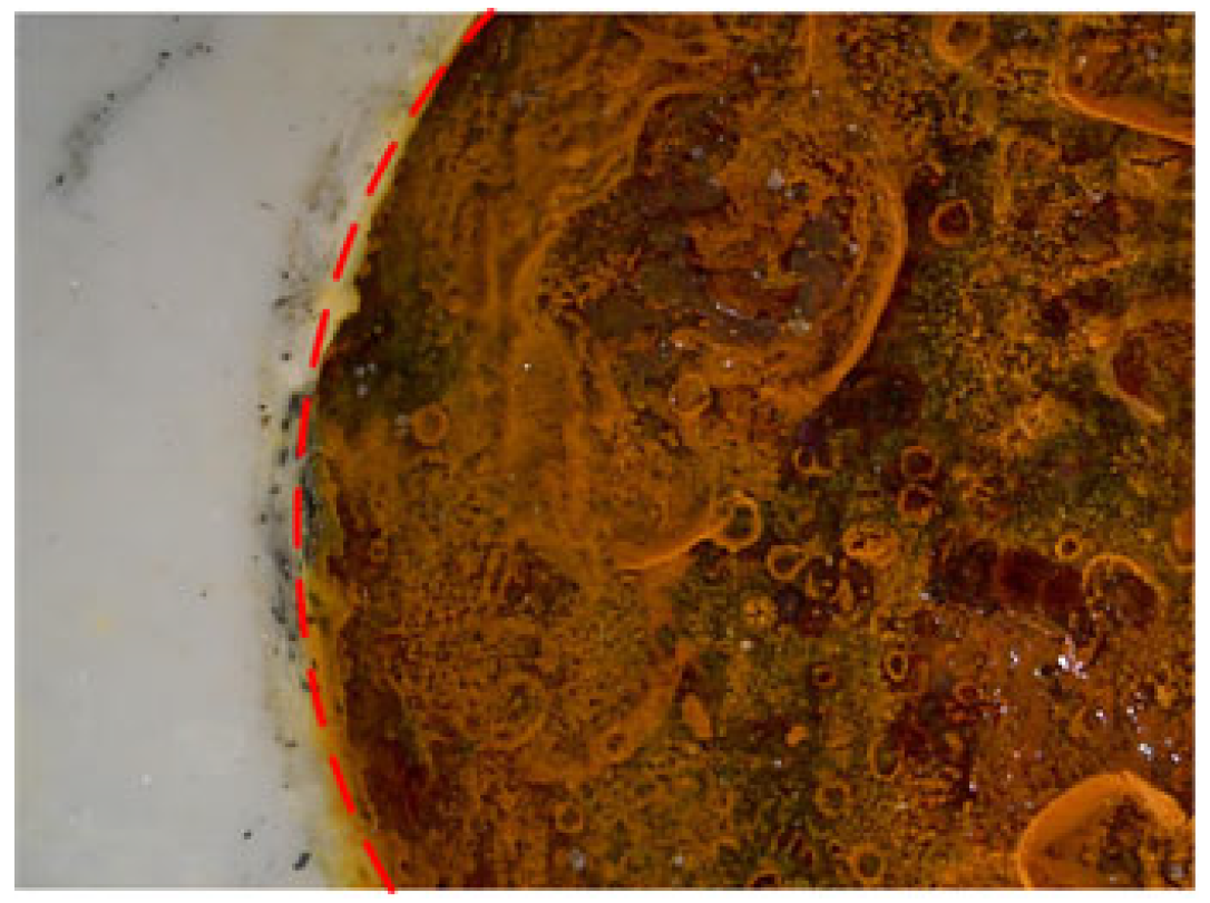
4.2. Optimal Protection Distance
5. Conclusions
Author Contributions
Funding
Institutional Review Board Statement
Informed Consent Statement
Data Availability Statement
Conflicts of Interest
References
- Hu, Q.; Yang, S.; Zhang, W.; Da, G.; Xu, X.; Wang, X. Corrosion failure analysis of engineering structural steels in tropical marine atmospheres: A comparative study of ordinary and new weathering steels. Eng. Fail. Anal. 2024, 156, 107830. [Google Scholar] [CrossRef]
- Qian, R.; Li, Q.; Fu, C.; Zhang, Y.; Wang, Y.; Jin, X. Atmospheric chloride-induced corrosion of steel-reinforced concrete beam exposed to real marine-environment for 7 years. Ocean Eng. 2023, 286, 115675. [Google Scholar] [CrossRef]
- Bhat, S.I.; Mobin, M.; Islam, S.; Zehra, S.; Islam, S.U. Recent advances in anticorrosive coatings based on sustainable polymers: Challenges and perspectives. Surf. Coat. Technol. 2024, 480, 130596. [Google Scholar] [CrossRef]
- Lin, S.; Li, D.; Zhou, Q.; Chu, M.; Sun, Y.; Liu, M.; Zheng, K.; Qiao, S.; Zhao, L.; Zhao, L.; et al. Study on corrosion perforation behavior of copper nickel alloy pipe during service in marine environment. Eng. Fail. Anal. 2023, 153, 107628. [Google Scholar] [CrossRef]
- Chen, Z.; Guo, X.; Zhang, L.; Lu, G.; Liu, M.; Liu, S. Anticorrosion mechanism of Al-modified phosphate ceramic coating in the high-temperature marine atmosphere. Surf. Coat. Technol. 2022, 441, 128572. [Google Scholar] [CrossRef]
- Zhang, H.; Sun, W.; Wang, L.; Wang, J.; Wang, S.; Liu, G. A Mechanically and Chemically Stable Superhydrophobic Coating for Preventing Marine Atmospheric Corrosion. Surf. Interfaces 2021, 27, 101537. [Google Scholar] [CrossRef]
- Lu, X.; Liu, Y.-W.; Zhao, H.-T.; Pan, C.; Wang, Z.-Y. Corrosion behavior of copper in extremely harsh marine atmosphere in Nansha Islands, China. Trans. Nonferrous Met. Soc. China 2021, 31, 703–714. [Google Scholar] [CrossRef]
- Li, Z.; Liu, J.; Xing, S.; Zhang, L.; Lu, Z.; Zhang, P. Failure Behavior and Damage Mechanism of Acrylic Polyurethane Coating in Tropical Marine Atmospheric Environment. Int. J. Electrochem. Sci. 2020, 15, 2511–2527. [Google Scholar] [CrossRef]
- Erdogan, C.; Swain, G. Conceptual Sacrificial Anode Cathodic Protection Design for offshore wind monopiles. Ocean Eng. 2021, 235, 109339. [Google Scholar] [CrossRef]
- Law, D.W.; Nicholls, P.; Christodoulou, C. Residual protection of steel following suspension of Impressed Current Cathodic Protection system on a wharf structure. Constr. Build. Mater. 2019, 210, 48–55. [Google Scholar] [CrossRef]
- NACE Standard RP0176-2003; Standard Recommended Practice RP0176. Item No. 21018. NACE International: Houston, TX, USA, 2003.
- Jeong, J.-A.; Jin, C.-K.; Chung, W.-S. Tidal Water Effect on the Hybrid Cathodic Protection Systems for Marine Concrete Structures. J. Adv. Concr. Technol. 2012, 10, 389–394. [Google Scholar] [CrossRef]
- Deshpande, P.; Kolekar, A.; Bhopale, A.; Kalendova, A.; Kohl, M. Impressed current cathodic protection (ICCP) of mild steel in association with zinc based paint coating. Mater. Today Proc. 2022, 50, 1660–1665. [Google Scholar] [CrossRef]
- Sun, J.; Sun, W.; Wang, L.; Xu, K.; Yang, Z.; Ma, Y.; Zhao, L.; Ma, S.; Xing, W.; Liu, G. Boosting the acid penetration barrier of epoxy-silica organic-inorganic hybrid coating via adjusting its molecular structures: Experimental and molecular dynamics simulation study. Colloids Surf. A Physicochem. Eng. Asp. 2024, 688, 133634. [Google Scholar] [CrossRef]
- Donkers, P.; Huinink, H.; Erich, S.; Reuvers, N.; Adan, O. Water permeability of pigmented waterborne coatings. Prog. Org. Coat. 2013, 76, 60–69. [Google Scholar] [CrossRef]
- Quelennec, B.; Duan, Z.; Delannoy, R.; Gay, N.; Briffaut, M.; Tognetti, V.; Delpouve, N.; Delbreilh, L.; Bredif, L.; Duthoit, A.; et al. Effect of physical and chemical ageing on barrier properties of epoxy coating. Constr. Build. Mater. 2023, 409, 133908. [Google Scholar] [CrossRef]
- Shi, C.; Shao, Y.; Wang, Y.; Meng, G.; Liu, B. Influence of submicron-sheet zinc phosphate synthesised by sol–gel method on anticorrosion of epoxy coating. Prog. Org. Coat. 2018, 117, 102–117. [Google Scholar] [CrossRef]
- Bordbar-Khiabani, A.; Yarmand, B.; Mozafari, M. Effect of ZnO pore-sealing layer on anti-corrosion and in-vitro bioactivity behavior of plasma electrolytic oxidized AZ91 magnesium alloy. Mater. Lett. 2020, 258, 126779. [Google Scholar] [CrossRef]
- Chen, Y.; Wu, L.; Yao, W.; Wu, J.; Xiang, J.; Dai, X.; Wu, T.; Yuan, Y.; Wang, J.; Jiang, B.; et al. Development of metal-organic framework (MOF) decorated graphene oxide/MgAl-layered double hydroxide coating via microstructural optimization for anti-corrosion micro-arc oxidation coatings of magnesium alloy. J. Mater. Sci. Technol. 2022, 130, 12–26. [Google Scholar] [CrossRef]
- Kumar, S.S.A.; Bashir, S.; Ramesh, K.; Ramesh, S. New perspectives on Graphene/Graphene oxide based polymer nanocomposites for corrosion applications: The relevance of the Graphene/Polymer barrier coatings. Prog. Org. Coat. 2021, 154, 106215. [Google Scholar] [CrossRef]
- Deng, P.; Shangguan, J.; Hu, J.; Huang, H.; Zhou, L. Anticorrosion Method Combining Impressed Current Cathodic Protection and Coatings in Marine Atmospheric Environment. Coatings 2024, 14, 524. [Google Scholar] [CrossRef]
- GB/T 700-2006; Carbon Structural Steels. Standardization Administration of the People’s Republic of China: Beijing, China, 2006.
- He, Y.; Lin, C.D.; Sun, F. A new and flexible design construction for orthogonal arrays for modern applications. Ann. Stat. 2022, 50, 1473–1489. [Google Scholar] [CrossRef]
- Chae, K.-S.; Choi, H.-K.; Ahn, J.-H.; Song, Y.-S.; Lee, D.Y. Application of Taguchi method and orthogonal arrays for characterization of corrosion rate of IrO2–RuO2 film. J. Mater. Sci. 2002, 37, 3515–3520. [Google Scholar] [CrossRef]
- Wang, K.; Kan, Y.; Zhu, Y.; Zhong, K.; Hu, J. Optimization of synthesis parameters for C-S-H/PCE nanocomposites: A comprehensive study using orthogonal experiments and multi-analysis approaches. Constr. Build. Mater. 2024, 417, 135332. [Google Scholar] [CrossRef]
- An, D.; Wang, Z.; Qin, L.; Wu, Y.; Lu, S.; Yang, H.; Ma, Z.; Mawignon, F.J.; Liu, J.; Hao, L.; et al. Preparation of MXene/EP coating for promising anticorrosion and superlow friction properties. Prog. Org. Coat. 2023, 183, 107779. [Google Scholar] [CrossRef]
- Araneda, A.A.B.; Kappes, M.A.; Rodríguez, M.A.; Carranza, R.M. Pitting corrosion of Ni-Cr-Fe alloys at open circuit potential in chloride plus thiosulfate solutions. Corros. Sci. 2022, 198, 110121. [Google Scholar] [CrossRef]
- Dan, N.; Yang, Y.; Ying, T.; Zeng, X. Corrosion Inhibition Effects of Corrosion Products on High-purity Mg and AZ91D under Thin Electrolyte Layers. J. Electrochem. Soc. 2022, 169, 091502. [Google Scholar] [CrossRef]
- Zheng, L.; Matin, N.S.; Landon, J.; Liu, K. CO2 loading-dependent corrosion of carbon steel and formation of corrosion products in anoxic 30wt.% monoethanolamine-based solutions. Corros. Sci. 2016, 102, 44–54. [Google Scholar] [CrossRef]
- Li, G.; Fang, H.; Hu, Y.; Chen, X.; Chu, Z.; Yang, Z. Construction of vinyl ester resins composite coatings via introducing silane-functionalized gra-phene oxide for enhancing comprehensive performance. Compos. Sci. Technol. 2022, 228, 109670. [Google Scholar] [CrossRef]
- Xu, A.; Zhang, F.; Jin, F.; Zhang, R.; Luo, B.; Zhang, T. The Evaluation of Coating Performance by Analyzing the Intersection of Bode Plots. Int. J. Electrochem. Sci. 2014, 9, 5116–5125. [Google Scholar] [CrossRef]
- Chen, J.; Li, X.; Bi, J.; Huo, D.; Liu, J.; Dong, J.; Zhan, C.; Nan, D. Paraphenylenediamine modified graphene oxide for enhancement protection performance of epoxy coating on Q235 steel. Diam. Relat. Mater. 2024, 148, 111425. [Google Scholar] [CrossRef]
- Wang, Z.; Li, X.; Zheng, H.; Deng, S.; Hou, Y.; Wu, Y.; Liu, M. A waterborne coating system for constructing inorganic-organic composite anti-corrosion and wear-resistant coating. Colloids Surf. A Physicochem. Eng. Asp. 2024, 694, 134120. [Google Scholar] [CrossRef]


| Element wt (%) | ||||||
|---|---|---|---|---|---|---|
| Material | C | Si | Mn | P | S | Fe |
| Q235 | 0.15 | 0.19 | 0.5 | 0.023 | 0.015 | Balance |
| Factors | Coating Damage Area (A)/% | Impressed Voltage (B)/V | Distance from the Point of Contact (C)/mm | |
|---|---|---|---|---|
| Level | ||||
| 1 | 1 | 0.6 | 30 | |
| 2 | 2 | 0.7 | 110 | |
| 3 | 3 | 0.8 | 190 | |
| 4 | 4 | 0.9 | 270 | |
| Experiment Number | Factors | Open-Circuit Potential/V | ||
|---|---|---|---|---|
| Coating Damage Area (A)/% | Impressed Voltage (B)/V | Distance from the Point of Contact (C)/mm | ||
| 1 | 1% | 0.6 | 30 | −0.47943 |
| 2 | 1% | 0.7 | 110 | −0.41565 |
| 3 | 1% | 0.8 | 190 | −0.42592 |
| 4 | 1% | 0.9 | 270 | −0.45362 |
| 5 | 2% | 0.6 | 110 | −0.49809 |
| 6 | 2% | 0.7 | 30 | −0.44548 |
| 7 | 2% | 0.8 | 270 | −0.44266 |
| 8 | 2% | 0.9 | 190 | −0.44156 |
| 9 | 3% | 0.6 | 190 | −0.49931 |
| 10 | 3% | 0.7 | 270 | −0.45523 |
| 11 | 3% | 0.8 | 30 | −0.48821 |
| 12 | 3% | 0.9 | 110 | −0.47701 |
| 13 | 4% | 0.6 | 270 | −0.48689 |
| 14 | 4% | 0.7 | 190 | −0.45052 |
| 15 | 4% | 0.8 | 110 | −0.47047 |
| 16 | 4% | 0.9 | 30 | −0.51598 |
| Experimental Number | Experiment Factor | ||
|---|---|---|---|
| Coating Damage Area (A)/% | Impressed Voltage (B)/V | Distance from the Point of Contact (C)/mm | |
| −1.775 | −1.964 | −1.929 | |
| −1.828 | −1.777 | −1.871 | |
| −1.92 | −1.817 | −1.807 | |
| −1.924 | −1.888 | −1.838 | |
| −0.444 | −0.491 | −0.482 | |
| −0.457 | −0.444 | −0.468 | |
| −0.480 | −0.454 | −0.452 | |
| −0.481 | −0.472 | −0.460 | |
| R | 0.037 | 0.047 | 0.031 |
| Applied Voltage /V | Test Point | Rs/(Ω·cm2) | Rc/(Ω·cm2) | CPEc − T/(F/cm2) | CPEc − P/(F/cm2) | Rp |
|---|---|---|---|---|---|---|
| 0.6 | #1 | 2619 | 9.92 × 10⁷ | 1.62 × 10⁻¹⁰ | 0.90393 | 9.92 × 10⁷ |
| #2 | 2719 | 3.81 × 10⁷ | 1.38 × 10⁻¹⁰ | 0.91123 | 3.81 × 10⁷ | |
| #3 | 2541 | 2.88 × 10⁷ | 1.61 × 10⁻¹⁰ | 0.90787 | 2.88 × 10⁷ | |
| #4 | 3563 | 2.61 × 10⁷ | 1.23 × 10⁻¹⁰ | 0.9226 | 2.61 × 10⁷ | |
| 0.7 | #1 | 1758 | 1.196 × 10⁸ | 1.561 × 10⁻¹⁰ | 0.90321 | 1.196 × 10⁸ |
| #2 | 3201 | 2.377 × 10⁸ | 1.317 × 10⁻¹⁰ | 0.91769 | 2.377 × 10⁸ | |
| #3 | 1806 | 2.01 × 10⁸ | 1.318 × 10⁻¹⁰ | 0.91212 | 2.01 × 10⁸ | |
| #4 | 2182 | 1.195 × 10⁸ | 1.251 × 10⁻¹⁰ | 0.91815 | 1.195 × 10⁸ | |
| 0.8 | #1 | 3149 | 1.207 × 10⁸ | 1.416 × 10⁻¹⁰ | 0.90746 | 1.207 × 10⁸ |
| #2 | 2965 | 1.426 × 10⁸ | 1.157 × 10⁻¹⁰ | 0.92724 | 1.426 × 10⁸ | |
| #3 | 3881 | 8.2522 × 10⁷ | 1.386 × 10⁻¹⁰ | 0.90982 | 8.252 × 10⁷ | |
| #4 | 3336 | 8.8855 × 10⁷ | 1.541 × 10⁻¹⁰ | 0.9053 | 8.886 × 10⁷ | |
| 0.9 | #1 | 2989 | 2.2756 × 10⁷ | 1.532 × 10⁻¹⁰ | 0.90584 | 2.277 × 10⁷ |
| #2 | 3672 | 6.6905 × 10⁷ | 1.206 × 10⁻¹⁰ | 0.91769 | 6.691 × 10⁷ | |
| #3 | 2444 | 1.172 × 10⁸ | 1.568 × 10⁻¹⁰ | 0.90356 | 1.172 × 10⁸ | |
| #4 | 3328 | 1.053 × 10⁸ | 1.448 × 10⁻¹⁰ | 0.90963 | 1.053 × 10⁸ |
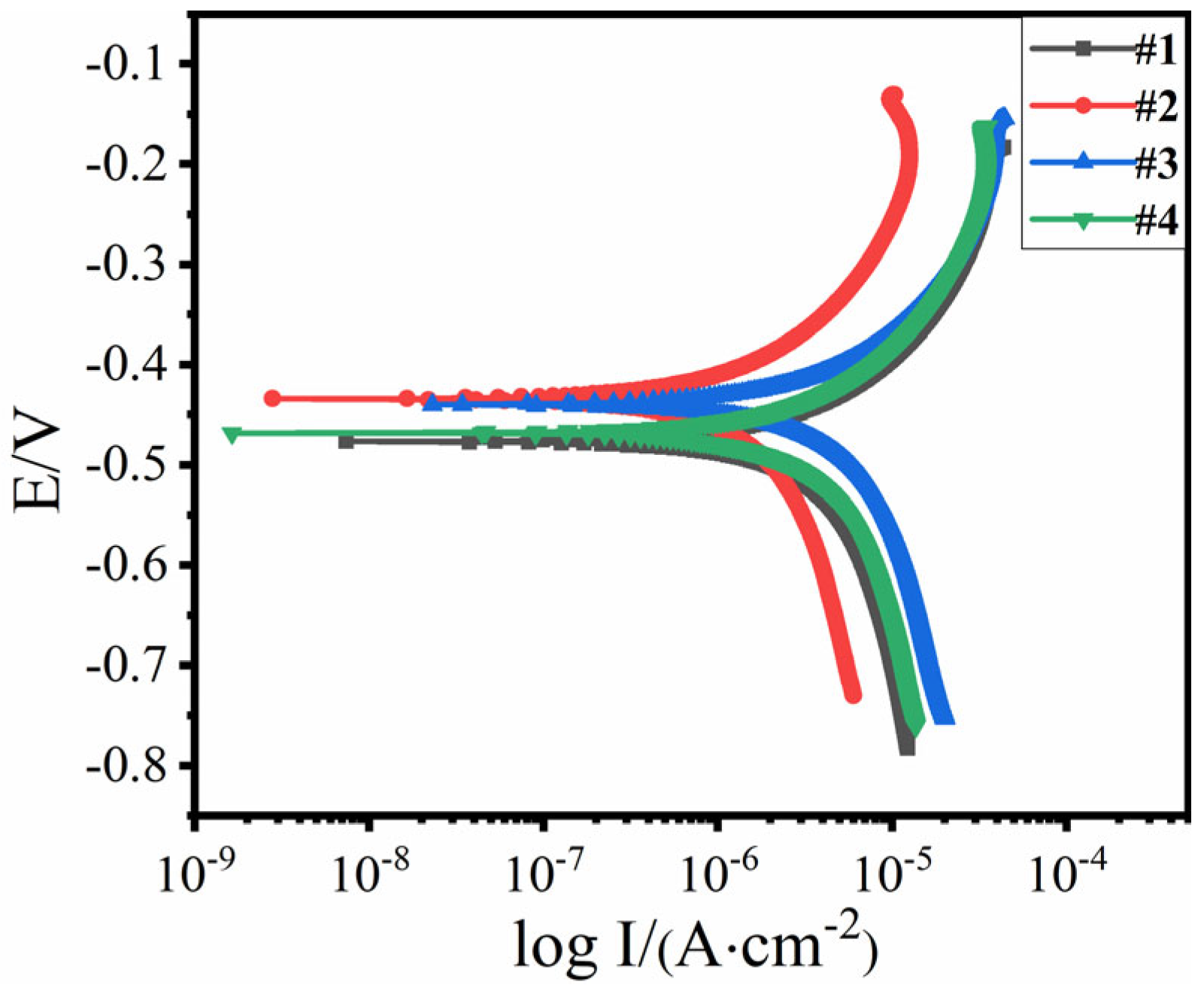
| Item | #1 | #2 | #3 | #4 |
|---|---|---|---|---|
| Corrosion potential/V | −0.4763 | −0.4343 | −0.4398 | −0.4679 |
| Corrosion current density/(10−6 A·cm−2) | 9.9722 | 5.0933 | 8.2284 | 14.4240 |
| Corrosion rate (mm/a) | 0.1170 | 0.0598 | 0.0965 | 0.1692 |
Disclaimer/Publisher’s Note: The statements, opinions and data contained in all publications are solely those of the individual author(s) and contributor(s) and not of MDPI and/or the editor(s). MDPI and/or the editor(s) disclaim responsibility for any injury to people or property resulting from any ideas, methods, instructions or products referred to in the content. |
© 2024 by the authors. Licensee MDPI, Basel, Switzerland. This article is an open access article distributed under the terms and conditions of the Creative Commons Attribution (CC BY) license (https://creativecommons.org/licenses/by/4.0/).
Share and Cite
Hu, J.; Liu, D.; Deng, P.; Shangguan, J.; Zheng, G.; Yang, J. Research on the Optimal Protection Parameters of Graphene Composite Conductive Coatings Combined with Impressed Current Cathodic Protection Technology in Marine Atmospheric Environments. Coatings 2024, 14, 1263. https://doi.org/10.3390/coatings14101263
Hu J, Liu D, Deng P, Shangguan J, Zheng G, Yang J. Research on the Optimal Protection Parameters of Graphene Composite Conductive Coatings Combined with Impressed Current Cathodic Protection Technology in Marine Atmospheric Environments. Coatings. 2024; 14(10):1263. https://doi.org/10.3390/coatings14101263
Chicago/Turabian StyleHu, Jiezhen, Dahai Liu, Peichang Deng, Juyu Shangguan, Guo Zheng, and Jingrong Yang. 2024. "Research on the Optimal Protection Parameters of Graphene Composite Conductive Coatings Combined with Impressed Current Cathodic Protection Technology in Marine Atmospheric Environments" Coatings 14, no. 10: 1263. https://doi.org/10.3390/coatings14101263