Article

Spraying Power Effect on Micro-Structure and Mechanical Property of TaSi2 Coating Prepared by Supersonic Air Plasma Spraying for SiC-Coated C/C Composites

by
Fei Liu
1,*,
Hejun Li
2,
Qiangang Fu
2,
Bolun Ji
1,
Lihao Chen
1,
Bilin Zhang
1,
Wei Zhang
3 and
Xinhai He
2,*
1
Xi’an Key Laboratory of Textile Composites, School of Materials Science and Engineering, Xi’an Polytechnic University, Xi’an 710048, China
2
State Key Laboratory of Solidification Processing, Northwestern Polytechnical University, Xi’an 710072, China
3
Faculty of Printing, Packaging Engineering and Digital Media Technology, Xi’an University of Technology, Xi’an 710048, China
*
Authors to whom correspondence should be addressed.
Coatings 2024, 14(10), 1268; https://doi.org/10.3390/coatings14101268
Submission received: 27 August 2024 / Revised: 29 September 2024 / Accepted: 30 September 2024 / Published: 3 October 2024
(This article belongs to the Special Issue Trends in Coatings and Surface Technology, 2nd Edition)

Abstract

:
In order to further improve the oxidation resistance of SiC-coated C/C composites used in extreme environments, TaSi2 coatings were deposited on the surfaces of SiC-coated C/C composites by supersonic air plasma spraying (SAPS) with different spraying power parameters, under other fixed parameter (gas flow, power feed rate, spraying distance and nozzle diameter) conditions. The micro-structures and phase characteristics of the TaSi2 coatings prepared with the four kinds of spraying powers (40 kW, 45 kW, 50 kW and 55 kW) were analyzed. Also, the inter-facial bonding strengths and fracture modes between the four TaSi2 coatings and the SiC coating were studied. The results showed that with an increase in the spraying power, the morphologies of the TaSi2 coatings appeared from loose to dense to loose. When the spraying power was 50 kW, the deposition rate reached a maximum of 39.8%. The TaSi2 coating presented an excellent micro-structure without obvious pores and microcracks, and its inter-facial bonding strength was 15.3 ± 2.3 N. Meanwhile, the fracture surface of the sample exhibited a brittle characteristic.

1. Introduction

SiC-coated C/C composites not only keep the outstanding physical, chemical and mechanical properties of C/C composites but also have a high temperature and good thermal stability and oxidation resistance [1,2,3,4]. However, when applied to thermal structure apartments, such as the heat shield, nose cones, front and precentrum of aerospace vehicles, SiC-coated C/C composites usually experience harsh working environments like heat flow scouring and ablation above 2000 °C, which demand the improvement of oxidation and ablation resistance [5,6,7,8,9,10].
Refractory metal silicide TaSi2 possesses a high melting point (Tm = 2200 °C), high temperature thermal stability, high thermal conductivity and an outstanding anti-oxidation property. Meanwhile, as the coefficient of thermal expansions (CTEs) of TaSi2 ( α T a S i 2 = 8.8 × 10⁻⁶ K−1), SiC ( α S i C = 4.5 × 10⁻⁶ K−1) and C/C composites ( α C / C = 1.0 × 10⁻⁶ K−1) decreases in sequence, the formed TaSi2/SiC double coating system could reduce thermal mismatch and improve the thermal mechanical property of the coating [11,12,13,14,15,16]. Accordingly, there is a lot of research about the anti-oxidation property of TaSi2. Shi, X.H. et al. prepared a TaSi2 coating on the surface of SiC-coated C/C composites by pack cementation and evaluated its static oxidation resistance in the air at 1500 °C. The TaSi2 coating showed a thickness of 200 μm without obvious pores and microcracks, which could protect SiC-coated C/C composites from oxidation for up to 233 h [17]; Niu, Y.R. et al. confirmed that a TaSi2 coating, deposited on a graphite matrix surface using vacuum plasma spraying, was able to occur with oxidation from 800 to 1000 °C to produce a glass SiO2 protection film and presented excellent thermal stability at 500–700 °C, compared with a MoSi2 coating [18]. In the aspect of focusing on its ablation resistance, Li, S.P. et al. found that TaSi2/SiC-coated C/C composites showed good ablation resistance, with only 7.7 × 10⁻⁴ g·s−1 mass ablation rate after ablation for 30 s in an oxyacetylene flame, which was reduced by 79% compared to C/C composites [19]. Wang, R.Q. et al. added TaSi2 to a ZrB2-SiC coating by means of low-pressure plasma spraying. Due to forming fine nanoscale particles and reducing porosity in the coating, the addition of TaSi2 effectively improved the mechanical and ablation resistance. It follows that a TaSi2 coating adopted by traditional preparation methods exhibits a certain application prospect as an anti-oxidation and anti-ablation coating for C/C composites [11]. However, few studies report and analyze the effect of processing parameters on the structure and properties of the TaSi2 coating. Meanwhile, in order to adapt to more severe service environments for C/C composites, the advent of newly developed coating preparation techniques such as atmospheric DC, RF and Microwave plasma torches largely moves toward being faster, more efficient and smarter. As to atmospheric DC, it has two electrodes, generally made from materials with high electric conductivity. When it works, a gas breakdown quickly occurs in the electrode gap, which forms a high-temperature electric arc and leads to thermal plasma formation and plasma jet output. As the thermal plasma and plasma jet are able to melt ultra-high temperature ceramics, this preparation method is widely used to generate excellent mechanical properties for coatings [20]. Among them, supersonic air plasma spraying (SAPS) could address past preparation problems of a low density and inter-facial bonding strength of the coating by means of its super-high temperature (10,000 °C) and the velocity of the plasma arc, and it has gradually been applied in anti-oxidation and anti-ablation coatings for C/C composites [21,22,23].
Therefore, in this paper, a TaSi2 coating was deposited on the surface of SiC-coated C/C composites by SAPS. The effect of spraying power parameters on the deposition rate, micro-structure, phase compositions and inter-facial bonding strength of the coating was systematically studied. In turn, the optimum spraying power value could be confirmed, and the research results could provide a certain theoretical basis for subsequent research. The research results of the optimization of spraying power parameters expect to provide a theoretical foundation for enhancing the preparation productivity and service life of TaSi2 ceramic coatings used in extremely harsh environments for SiC-coated C/C composites using SAPS.

2. Materials and Methods

2.1. Preparation of the TaSi2 Coatings

Specimens (10 mm × 10 mm × 10 mm) served as the substrates, cropped from bulk 2D C/C composites; their density was 1.73 g/cm3. The small cubic specimens were hand-polished using 80-, 200- and 400-grit SiC papers, respectively. Then, they were cleaned ultrasonically in ethanol and finally dried at 333 K for 1–2 h. The SiC inner coating was prepared by pack cementation. The specimens were fully covered with original mixed powders as follows: 65%–85% Si, 10%–20% graphite and 5%–15% Al2O3. Other detailed preparation processes are referred to in [24].
The TaSi2 coatings prepared by different spraying powers were obtained by HEPJ-II SAPS (Jin Ye Long Cheng Science and Technology Co., Ltd., Beijing, China). The 99% purity TaSi2 original powders were bought from Hua Wei Rui Ke Chemical Co., Ltd., Beijing, China. The powders were uniformly mixed with an aqueous solution of polyvinyl alcohol and formed a slurry. Then, they were processed by a centrifugal spray dryer, manufactured by Wuxi Dongsheng Spray Granulating and Drying Equipment Plant, Jiangsu, China, in order to obtain a uniform shape and liquid TaSi2 particles (seen in Figure 1) to meet the preparation requirements of the supersonic plasma spraying. The particles were subsequently dried at 333 K for 1–2 h and then carried into the powder feeder of the SAPS equipment. Meanwhile, through adjusting the technological parameters, including spraying power, gas flow, power feed rate, spraying distance and nozzle diameter, thermal spraying coatings with different especial micro-structures and mechanical properties could be obtained. Among them, spraying power could mostly influence the micro-structures, density and mechanical properties of the coatings because its value size directly determined the molten degree of the spraying particles, and it influenced the deposition modes to have distinct macro-mechanical property coatings that were affected by different coating micro-structures. Therefore, this paper mainly analyzed the effects of different power values on the micro-structures, phase distribution and inter-facial bonding strength of TaSi2 coatings.
The plasma spraying preparation process was as follows. First, TaSi2 powders with a super-high velocity and temperature caused by high plasma flame flow were impacted on the substrate to form flattened droplets. Then, they were simultaneously accumulated and solidified to form a coating. In this paper, the four kinds of TaSi2 coatings were obtained by 40 kW, 45 kW, 50 kW and 55 kW spraying powers, respectively. The spraying parameters for preparing the TaSi2 coatings are listed in Table 1.

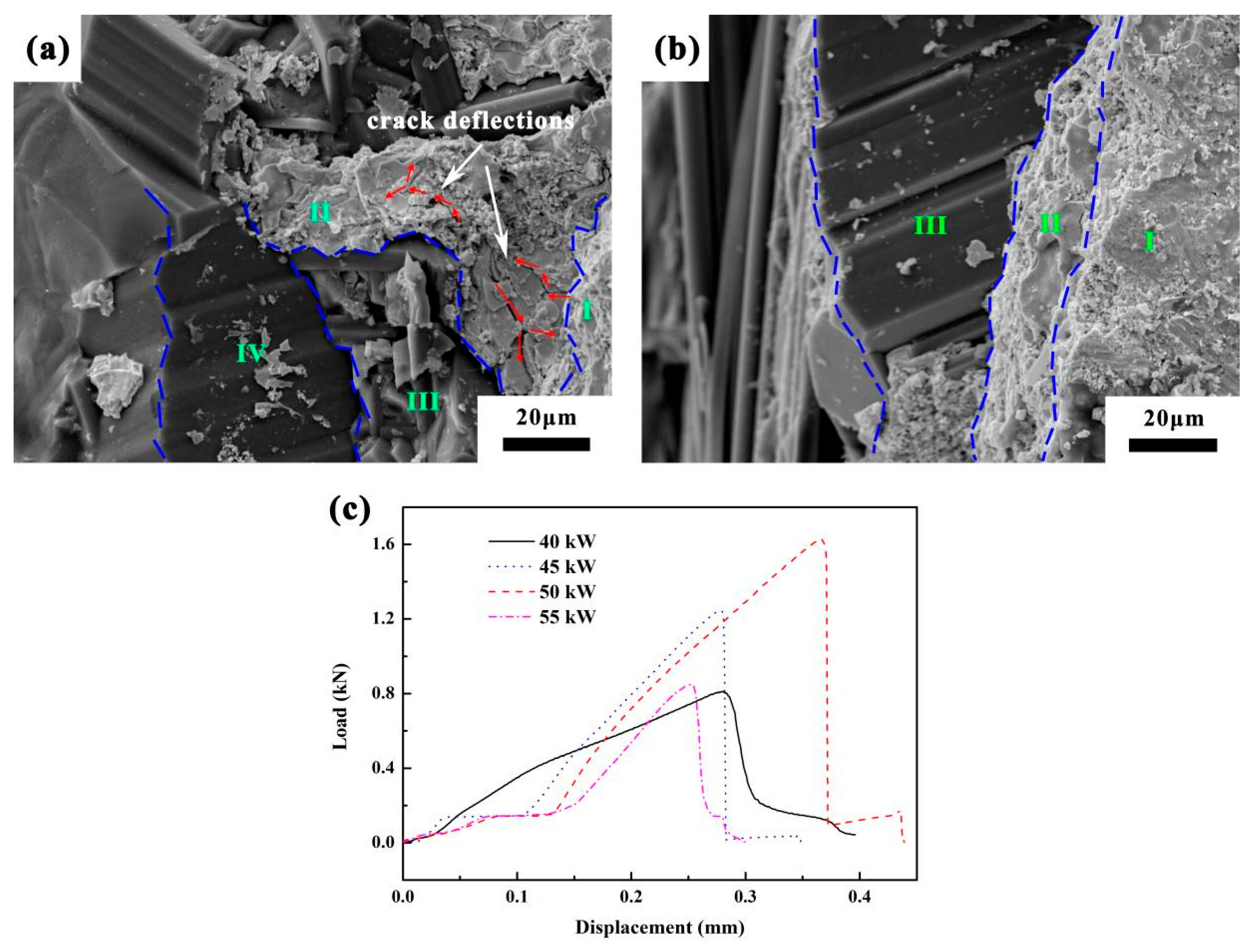
2.2. Micro-Structure Characterization

The crystalline structures of the TaSi2 coatings deposited on the SiC coatings were analyzed by X-ray diffraction (XRD, Rigaku D/max-3C, Tokyo, Japan) with a Cu K α radiation (λ = 0.1542 mm) produced at 40 kV and 35 mA. The analyzed range of the diffraction angle 2 θ ranged from 10 ° to 90 ° , with a step width of 0.033 ° . The micro-topographies and element distribution of the TaSi2 coatings were measured by a scanning electron microscope (SEM, JSM-6460, JEOL Ltd., Mitaka, Japan), equipped with an energy dispersive spectroscope (EDS, JSM-6460, JEOL Ltd., Mitaka, Japan).

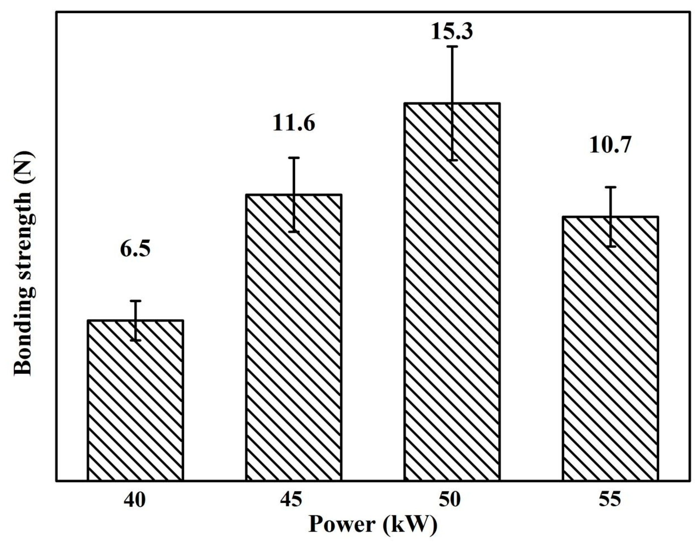
2.3. Inter-Facial Bonding Strength Test of the TaSi2 Coatings
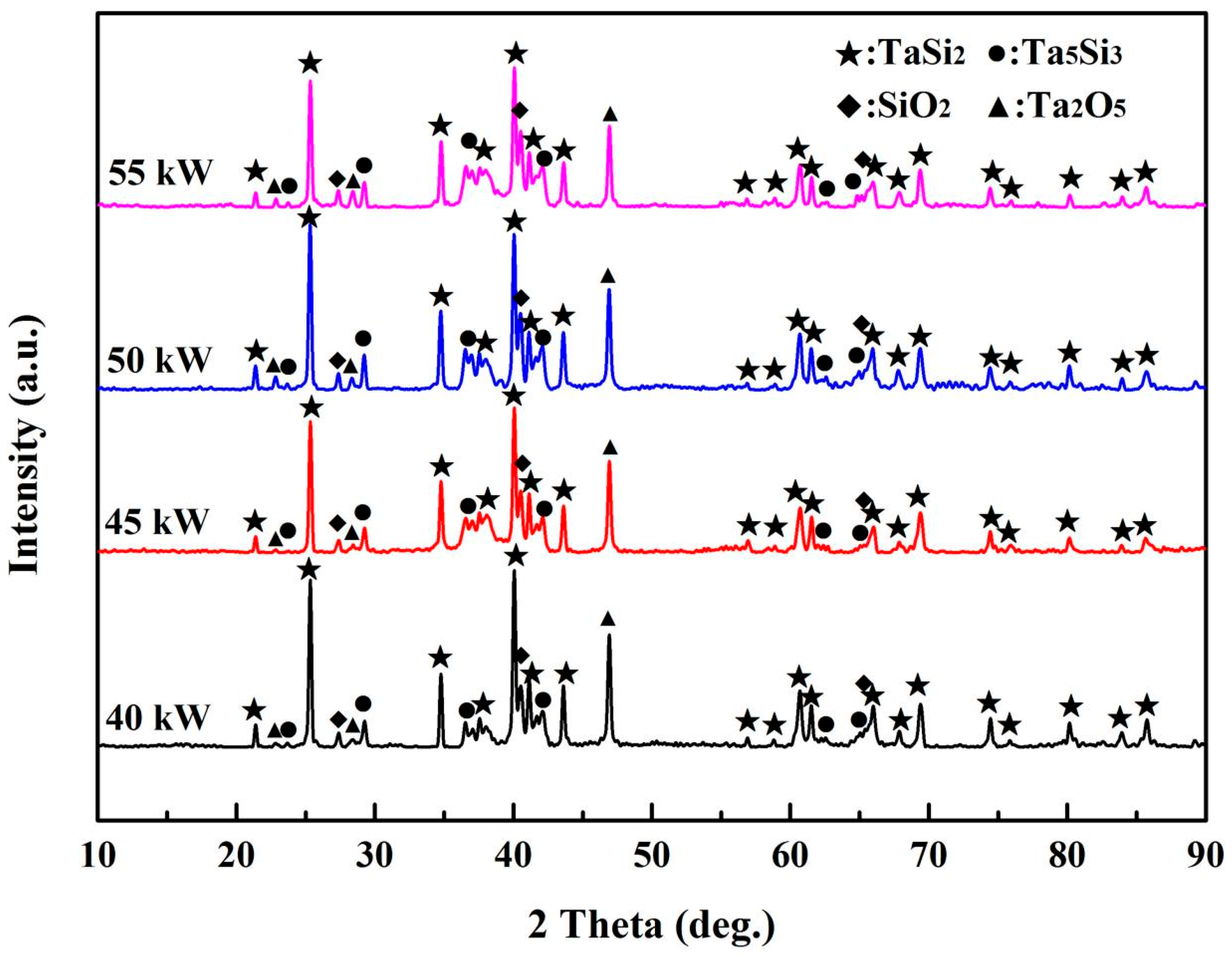
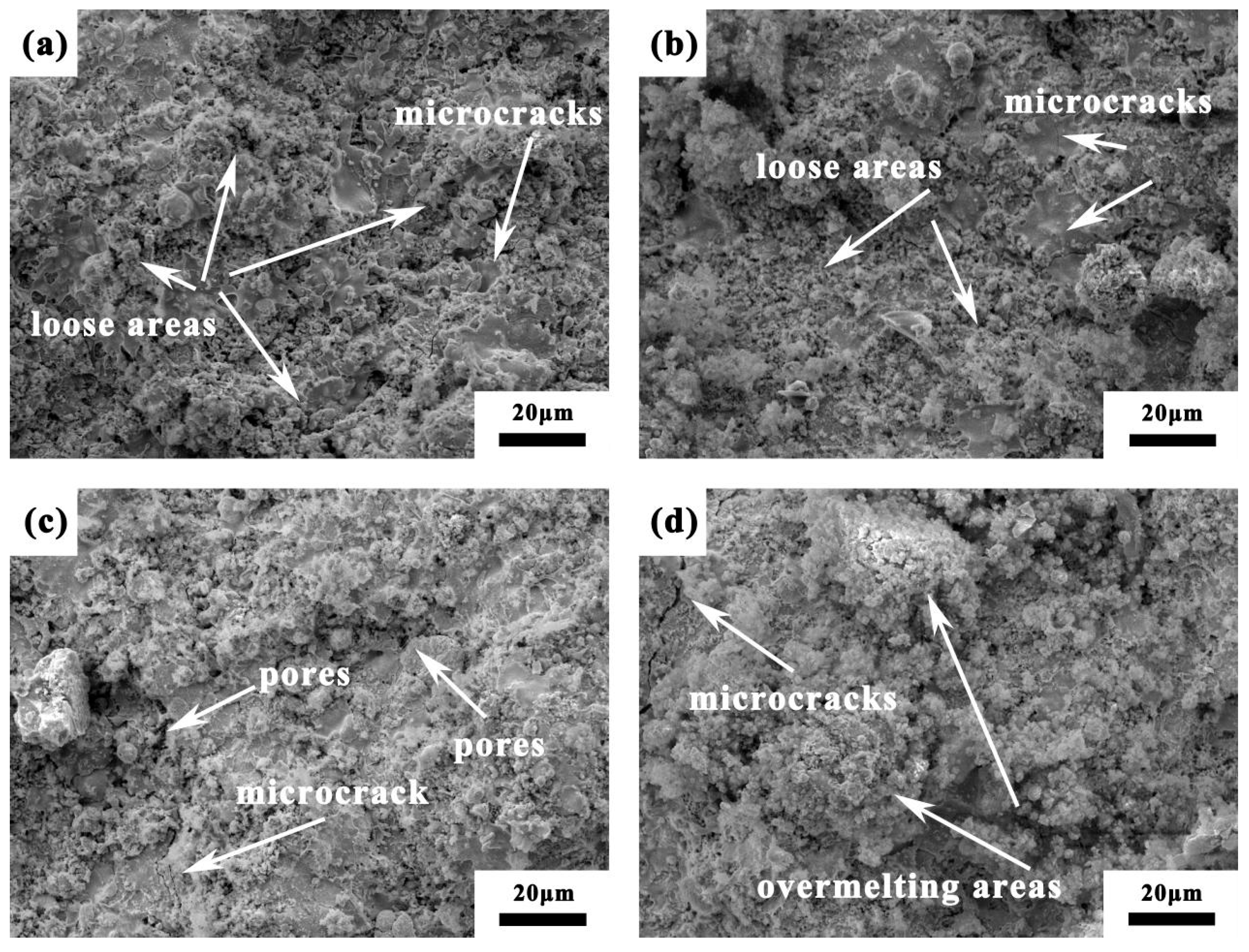
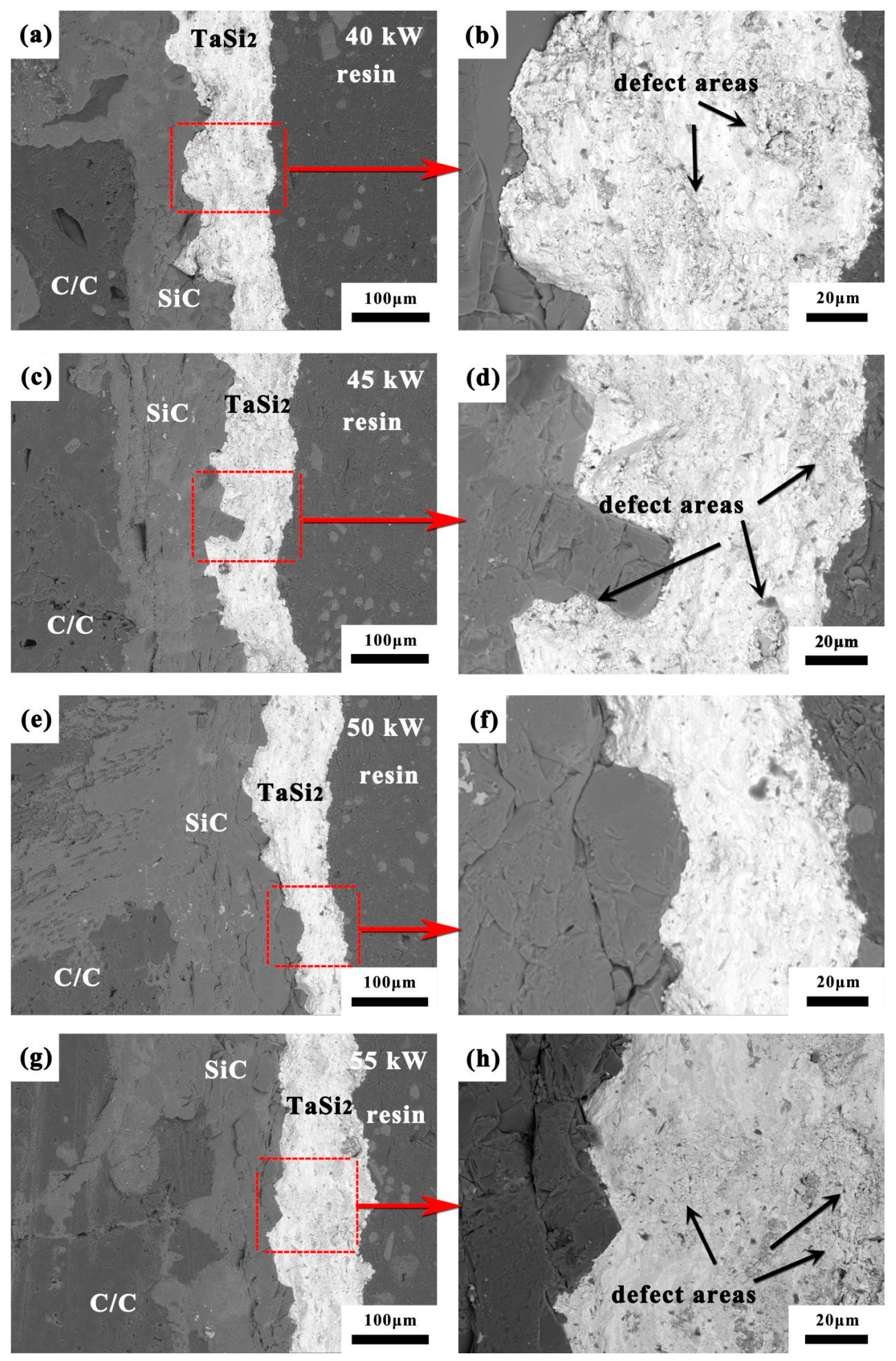
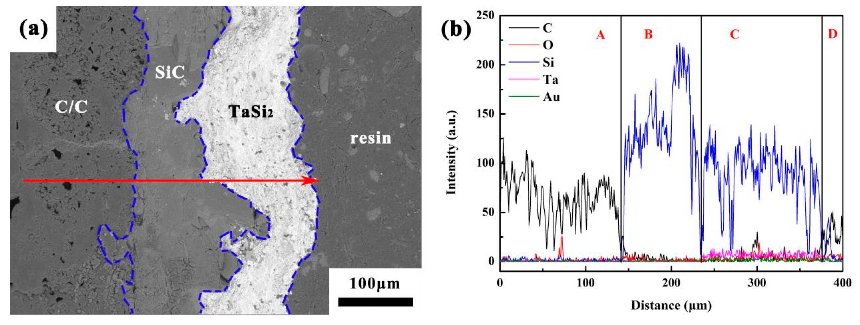
The inter-facial bonding strength between the TaSi2 coating and the SiC-coated C/C composites was researched using a universal testing machine (CMT534-30KN microcomputer-controlled electronic universal tester, Sansi Technology Ltd., Zhejiang, China). According to the requirements of GB/T8642-88 [25], in Figure 1, the test diagram of the tensile method is shown. The end faces of two stainless steel dual parts were evenly coated with modified acrylic adhesive, and the samples were adhered to the end faces of the dual parts through the adhesive. Next, the samples were positioned at room temperature for 15 min and then cured for 24 h. The dual parts adhering to the sample were installed on the machine for testing until the sample was disconnected, and the effective sample was not less than 5.

3. Results

Figure 2 shows the XRD result and surface morphology of the TaSi2 particles for plasma spraying. The TaSi2 particles mainly contain a TaSi2 phase with a little Ta5Si3 impurity and present an ovoid shape and have an average diameter of 40 μm. There is an area of dent in every particle, attributed to the volatilization of solvents such as aqueous PVA.
Figure 3a exhibits the surface morphology of SiC coatings prepared by pack cementation. It can be seen that SiC grains appear in a hexagonal crystal structure, proving that the coating mainly includes an α-SiC phase with a certain surface roughness. This surface structure could improve the adhesion of molten TaSi2 particles in the process of spraying and the mechanical property of the TaSi2 coating. Figure 3b shows the effect of spraying power on the deposition rate of the TaSi2 particles. When the spraying power value increased, the particle deposition rate ascended first and then descended. When the spraying power was up to 50 kW, the deposition rate reached a maximum of 39.8%. The major reason was that the energy of the plasma jet continuously enhanced as the spraying power increased; the particles could be melted more fully and had a high degree of flatness. However, when the spraying power was 55 kW, the particles obtained excessive heat, which intensified the rate of the oxidation reaction and reduced the flying speed; the deposition rate correspondingly declined.
Figure 4 states the XRD results of TaSi2 coating surfaces prepared by SAPS at different spraying powers. All four kinds of the coatings included TaSi2, Ta5Si3, SiO2 and Ta2O5 phases. With the power increases, the intensities of the feature peaks of the SiO2 and Ta2O5 phases constantly enhanced, signaling that increasing plasma jet energy could accelerate the oxidation reaction of the TaSi2 particles to generate more oxidation products. The related chemical equation is as follows:
4TaSi2(s) + 13O2(g) = 2Ta2O5(s) + 8SiO2(s)
Figure 5 displays the surface morphologies of the TaSi2 coatings prepared by SAPS at different spraying powers. It can be seen that with the increase in spraying power, the coatings presented a loose to dense and then loose structure. In Figure 5a, the coating exhibits more pores, accumulating of a lot of unmelted or half-melted particles on the surface. The reason is that due to the low spraying power, flying particles acquiring inadequate thermal energy from the plasma jet fail to be melted fully. When the unmelted and half-melted flying particles collide with each other, a portion of which involves in-air collisions and pile-ups, the other part could splash when impacting the coating surface. As the spraying power shown in Figure 5c was 50 kW, the coating showed a dense structure with few unmelted and half-melted particles, attributed to the high degree of flattened and sufficiently melted particles. When the power rose to 55 kW, the coating surface had more excessive melted particles and large microcracks; because the thermal energy of flying particles was too large, the particles overmelted and aggregated, resulting in a reduction in flying velocity and increase in oxidation reaction. Finally, the above problems could produce more thermal stress in the coating in the process of cooling.
Figure 6 shows cross-section images of the TaSi2 coatings prepared by different spraying powers. It can be seen that their average widths were about 90–110 μm, and the bonding modes between the coatings and SiC coatings were mechanical combinations without obvious penetrating or big cracks. When the spraying power was 40 kW, there were some loose areas including the pile of pores and small spheroidal particles. Due to absorbing less heat, flying particles existing in unmelted and half-melted states could not be fully flattened but embedded in the coating surface as they impacted on it. With the increase in the spraying power, the loose areas and pores in the coating decreased, and its density improved. When the spraying power was up to 55 kW, there were no obvious accumulation areas of small particles, but some overmelting regions in the coating resulted from the agglomeration of the overmelted particles. Also, some loose areas appeared again; as the flying particles were imposed on the substrate, some air was carried in them.
Figure 7 presents the cross-sectional analyzed results of the EDS elemental line scanning of the sample prepared at 45 kW. The C/C substrate, SiC inner coating, TaSi2 spraying coating and resin coating are, respectively, marked by the A, B, C and D regions. It can be seen that the A region includes most of the C element and a little of the O element, in which the O element came from the preparation process of the C/C composites. The B region is made of Si and C elements. The C region, corresponding to the TaSi2 coating, has Si, Ta and O elements, suggesting that the coating was oxidized slightly in the process of plasma spraying. The results conform to the XRD analysis in Figure 3. In addition, the Au element coming from the experimental preparation can be ignored.
Figure 8 shows the cross-sectional bonding strength values of the samples by different spraying powers. It can be seen that as the spraying power increased, the bonding strength value rose at the beginning and then declined. When the spraying power was 50 kW, the coating bonding strength reached a maximum 15.3 ± 2.3 N. Due to inadequate fusion and flattening when particles impacted the substrate surface at the low power, they could partly be piled in the ways of their original spherical structure to produce more pores in the coating, resulting in poor bonding strength. However, as the spraying power increased to 55 kW, the flying particles were easily overmelted to agglomerate and oxidize deeply with oxygen, resulting in more formation of thermal stress, pores and microcracks in the coating. These defects could reduce the density and inter-facial bonding of the coating. Therefore, the flying particles absorbing suitable heat at 50 kW could be fully melted and flattened to form a dense coating with few pores which has the best bonding strength.
Figure 9 displays the fracture morphology of the sample prepared by SAPS at 40 kW and 50 kW and the load–displacement curves of the samples at different powers. Seen from Figure 8, the fracture appearance is rough and has a hierarchical and pseudoplastic characteristic, and it is divided into four regions marked by I, II, III and IV. Meanwhile, microcracks in the TaSi2 coating happened to deflect to uniformly release applied load stress. The main reason is that pores in the coating diverted the crack tips, the red-colored arrows in Figure 9a. The inter-facial morphology of the sample prepared at 50 kW in Figure 9b obviously emerged with a brittle rupture characteristic due to the smooth fracture of three regions marked as I, II and III, respectively. From the II region in Figure 9b, it can also be proved that the particles are adequately melted and have a good performance of spreading after being flattened, and the coating appears dense without obvious microcracks and pores.
From the four load-displacement curves of the samples in Figure 9c, it can be seen that when the load was at the maximum, the curve of the sample at 40 kW sharply dropped, and its whole curve presented a steplike feature and had a pseudoplastic characteristic. The main reason is that when the load imposed on the coating, the microcracks could occur with directional deflection as they extended to pores existing in the coating. With the spraying power increased, the curves obviously exhibited a brittle rupture characteristic, and the abilities of bearing load ascended first and then descended. When the spraying power was 50 kW, the sample had the best bearing ability of up to 1.63 kN. There are two reasons to explain the above phenomena. First, the more density the coating has, the more load it can bear. According to the SEM surface images of the coatings at different spraying powers in Figure 4, the TaSi2 coating prepared at 50 kW spraying power exhibited the best dense micro-structure. Second, as the spraying power increased, the oxidation degree of the flying particles in the process of spraying enhanced, resulting in the obvious brittleness property due to producing more glass-phase SiO2 in the TaSi2 coating, showcased by the XRD analysis in Figure 3. In addition, attributed to the effect of the adhesive, the curve in the beginning stayed parallel to the X-axis when the displacement increased.

4. Conclusions

Due to the sufficient melting and flattening of the TaSi2 particles in the process of spraying, the TaSi2 coating was dense with little pores and microcracks, when the spraying power was 50 kW. When the spraying power was low, the fracture mode of the TaSi2 coating was pseudoplastic due to the presence of pores in the coating. As the spraying power increased, the coating exhibited a brittle fracture because of the dense micro-structure and more glass-phase SiO2 in the coating. When the power was 50 kW, the TaSi2 coating combined mechanical interlock with the SiC coating, and its inter-facial bonding strength was 15.3 ± 2.3 N. These research results will provide a theoretical basis to improve the preparation efficiency of coatings and the micro-structure and mechanical properties of TaSi2-based coatings by SAPS.

Author Contributions

Conceptualization, F.L.; methodology, F.L. and Q.F.; validation, H.L. and X.H.; formal analysis, F.L., B.J. and L.C.; investigation, F.L., W.Z. and B.Z.; data curation, F.L., B.J., L.C. and B.Z.; writing—original draft preparation, F.L.; writing—review and editing, F.L., H.L. and X.H. All authors have read and agreed to the published version of the manuscript.

Funding

This work was funded by the National Natural Science Foundation of China, Grant number 52402055; the Key Research and Development Project of Shaanxi Province, Grant number 2023YBGY466; the Science and Technology Plan Project of Xi’an City, Grant number 23GXFW0015; and the Key Laboratory of Textile Composites of Xi’an City, Grant number xafzfc-zd01.

Institutional Review Board Statement

Not applicable.

Informed Consent Statement

Not applicable.

Data Availability Statement

Data are contained within the article.

Conflicts of Interest

The authors declare no conflicts of interest.

References

  1. Li, T.; Zhang, Y.L.; Lv, J.; Fu, Y.Q.; Li, J.C. Long-term oxidation behaviors of Si-Cr-W multiphase coating on SiC coated C/C composites at 1773 K and 1973 K. Corros. Sci. 2022, 205, 110417. [Google Scholar] [CrossRef]
  2. Shi, Y.A.; Zha, B.L.; Sun, Z.S.; Shen, Q.; Miao, W.B.; Gao, Y. Air plasma ablation/erosion test for 4D C/C composites used in the throat of solid rocket motor. Ceram. Int. 2022, 11, 15582–15593. [Google Scholar] [CrossRef]
  3. Yu, Y.L.; Feng, G.H.; Jia, Y.J. Nanosized (Zr, Hf)O2 coating reinforced by AlN whiskers for the ablation protection of SiC coated C/C composites. J. Eur. Ceram. Soc. 2023, 9, 3959–3968. [Google Scholar] [CrossRef]
  4. Ren, X.R.; Yuan, R.M.; Wang, P.P.; Li, H.J.; Hou, X.H.; Zhang, Y.L. HfB2-SiC-MoSi2 oxidation resistance coating fabricated through in-situ synthesis for SiC coated C/C composites. J. Alloys Compd. 2017, 722, 69–76. [Google Scholar]
  5. Li, T.; Zhang, Y.L.; Fu, Y.Q.; Sun, J.; Li, J. Siliconization elimination for SiC coated C/C composites by a pyrolytic carbon coating and the consequent improvement of the mechanical property and oxidation resistances. J. Eur. Ceram. Soc. 2021, 41, 5046–5055. [Google Scholar] [CrossRef]
  6. Brisebourg, M.Q.; Rebillat, F.; Teyssandier, F. Oxidation of β-SiC at high temperature in Ar/O2, Ar/CO2, Ar/H2O gas mixtures: Active/passive transition. J. Eur. Ceram. Soc. 2018, 38, 4309–4319. [Google Scholar] [CrossRef]
  7. Zhou, L.; Fu, Q.G.; Hu, D.; Zhang, J.P.; Wei, Y.L.; Zhu, J.; Song, J.Y.; Tong, M.D. A dense ZrB2-SiC-Si/SiC-Si coating to protect carbon/carbon composites against oxidation at 1773 K and 1973 K. Corros. Sci. 2021, 183, 109331. [Google Scholar] [CrossRef]
  8. Ren, X.R.; Chu, H.G.; Wu, K.Y.; Zhang, A.N.; Huang, M.L.; Ma, C.; Liu, H.F.; Feng, P.Z. Effect of the ZrB2 content on the oxygen blocking ability of ZrB2-SiC coating at 1973K. J. Eur. Ceram. Soc. 2021, 41, 1059–1070. [Google Scholar] [CrossRef]
  9. Zhang, P.; Fu, Q.G.; Cheng, C.Y.; Zhu, X.F.; Huang, J.G.; Zhang, J.P.; Li, W. Comparing oxidation behaviors at 1773 K and 1973 K of HfB2-MoSi2/SiC-Si coating prepared by a combination method of pack cementation, slurry painting and in-situ synthesis. Surf. Coat. Technol. 2020, 403, 126418. [Google Scholar] [CrossRef]
  10. Ren, X.R.; Li, H.J.; Chu, Y.H.; Li, K.Z.; Qian, Q.G. ZrB2-SiC gradient oxidation protective coating for carbon/carbon composite. Ceram. Int. 2014, 40, 7171–7176. [Google Scholar] [CrossRef]
  11. Wang, R.Q.; Zhu, S.Z.; Huang, H.B.; Wang, Z.F.; Liu, Y.B.; Ma, Z.; Qian, F. Low-pressure plasma spraying of ZrB2-SiC coatings on C/C substrate by adding TaSi2. Surf. Coat. Technol. 2021, 420, 127332. [Google Scholar] [CrossRef]
  12. Ren, Y.; Qian, Y.H.; Xu, J.J.; Zuo, J.; Li, M.S. Ultra-high temperature oxidation resistance of ZrB2-20SiC coating with TaSi2 addition on siliconized graphite. Ceram. Int. 2019, 45, 15366–15374. [Google Scholar] [CrossRef]
  13. Du, B.; Hong, C.Q.; Zhang, X.H.; Wang, A.Z.; Sun, Y.Q. Ablation behavior of advanced TaSi2-based coating on carbon-bonded carbon fiber composite/ceramic insulation tile in plasma wind tunnel. Ceram. Int. 2018, 44, 3505–3510. [Google Scholar] [CrossRef]
  14. Feng, T.; Li, H.J.; Fu, Q.G.; Wu, H.; Shen, X.T. Influence of Cr content on the microstructure and anti-oxidation property of MoSi2-CrSi2-Si multi-composition coating for SiC coated carbon/carbon composites. J. Alloys Compd. 2010, 501, L20–L24. [Google Scholar] [CrossRef]
  15. Peng, F.; Speyer, R.F. Oxidation resistance of fully dense ZrB2 with SiC, TaB2, and TaSi2 additives. J. Am. Ceram. Soc. 2008, 91, 1489–1494. [Google Scholar] [CrossRef]
  16. Zhou, S.F.; Sun, X.Q.; Carr, W.N. A micro variable inductor chip using MEMS relays. In Proceedings of the 1997 International Conference on Solid-State Sensors and Actuators, Chicago, IL, USA, 19 June 1997; pp. 1137–1140. [Google Scholar]
  17. Shi, X.H.; Zeng, X.R.; Li, H.J.; Fu, Q.G.; Zou, J.Z. TaSi2 Oxidation protective coating for SiC coated carbon/carbon composites. Rare Met. Mater. Eng. 2011, 40, 403–406. [Google Scholar]
  18. Niu, Y.R.; Huang, L.P.; Zhai, C.H.; Zeng, Y.; Zheng, X.B.; Ding, C.X. Microstructure and thermal stability of TaSi2 coating fabricated by vacuum plasma spray. Surf. Coat. Technol. 2015, 279, 1–8. [Google Scholar] [CrossRef]
  19. Li, S.P.; Li, K.Z.; Li, H.J. Ablation property of SiC-TaSi2 coated carbon/carbon composites. Surf. Rev. Lett. 2010, 17, 487–491. [Google Scholar] [CrossRef]
  20. Gabbar, H.A.; Darda, S.A.; Damideh, V.; Hassen, T.; Aboughaly, M.; Lisi, D. Comparative study of atmospheric pressure DC, RF, and microwave thermal plasma torches for waste to energy applications. Sustain. Energy Techn. Assess. 2021, 47, 101447. [Google Scholar] [CrossRef]
  21. Kuzmin, V.; Gulyaev, I.; Sergachev, D.; Tambovcev, A.; Palagushkin, B.; Matveev, S.; Shirobokov, O. The structure and characteristics of wear-resistant coatings obtained by supersonic plasma spraying. Key Eng. Mater. 2022, 910, 1087–1095. [Google Scholar] [CrossRef]
  22. Kumar, R.K.; Kamaraj, M.; Seetharamu, S.; Pramod, T.; Sampathkumaran, P. Effect of spray particle velocity on cavitation erosion resistance characteristics of HVOF and HVAF processed 86WC-10Co4Cr hydro turbine coatings. J. Therm. Spray Technol. 2016, 25, 1217–1230. [Google Scholar] [CrossRef]
  23. Zamharir, M.J.; Asl, M.S.; Zakeri, M. Microstructure of spark plasma coated ultrahigh temperature ZrB2-SiC-Si composites on graphite substrate. Silicon 2023, 15, 6015–6024. [Google Scholar] [CrossRef]
  24. Liu, F.; Li, H.J.; Zhang, W.; Yao, X.Y.; Fu, Q.G. Impact of introducing SiC and Si on microstructure and oxidation resistance of MoSi2/SiC coated C/C composites prepared by SAPS. Vacuum 2020, 179, 109477. [Google Scholar] [CrossRef]
  25. GB/T 8642-2002; Thermal Spraying—Determination of Tensile Adhesive Strength. National Standards of the People’s Republic of China: Beijing, China, 2002.
Figure 1. Schematic of stretch method device.
Coatings 14 01268 g001
Figure 2. The XRD pattern and SEM image of TaSi2 particles used for plasma spraying.
Coatings 14 01268 g002
Figure 3. (a) SEM image of SiC surface; (b) effect of spraying power on the deposition rate of TaSi2 particles.
Coatings 14 01268 g003
Figure 4. The XRD patterns of TaSi2 coating surfaces prepared at different spraying powers.
Coatings 14 01268 g004
Figure 5. SEM images of surface morphologies of TaSi2 coatings at different spraying powers. (a) 40 kW; (b) 45 kW; (c) 50 kW; (d) 55 kW.
Coatings 14 01268 g005
Figure 6. Backscattered electron images of the cross-section of the outer coatings prepared by SAPS with different powers. (a) 40 kW; (c) 45 kW; (e) 50 kW; (g) 55 kW; (b,d,f,h) are the local magnified images of (a,c,e,g), respectively.
Coatings 14 01268 g006
Figure 7. Line scanning images of elemental composition of the TaSi2 coatings prepared by SAPS at 45 kW. (a) Backscattered electron cross-section image; (b) line scanning image.
Coatings 14 01268 g007
Figure 8. Bonding strength of TaSi2 coatings prepared by SAPS at different spraying powers.
Coatings 14 01268 g008
Figure 9. SEM fracture morphology images of the sample prepared at 40 kW and 50 kW spraying powers and load–displacement curves of samples prepared at different spraying powers. (a) 40 kW; (b) 50 kW; (c) load–displacement curves.
Coatings 14 01268 g009
Table 1. Spraying parameters of the TaSi2 coatings prepared by SAPS.
ParametersValues
Spraying power (kW)40, 45, 50, 55
Main gas flow (Ar), L/min75
Carrier gas (Ar), L/min10
The second gas (H2), L/min5
Power feed rate (g/min)20
Spraying distance (mm)100
Nozzle diameter (mm)5.5
Disclaimer/Publisher’s Note: The statements, opinions and data contained in all publications are solely those of the individual author(s) and contributor(s) and not of MDPI and/or the editor(s). MDPI and/or the editor(s) disclaim responsibility for any injury to people or property resulting from any ideas, methods, instructions or products referred to in the content.

