Article

Performance of Cobalt-Doped C3N5 Electrocatalysis Nitrate in Ammonia Production

1
School of Materials Science and Engineering, Jingdezhen Ceramic University, Jingdezhen 333403, China
2
School of Iron and Steel, Soochow University, Suzhou 215000, China
*
Authors to whom correspondence should be addressed.
These authors contributed equally to this work.
Coatings 2024, 14(10), 1327; https://doi.org/10.3390/coatings14101327
Submission received: 20 September 2024 / Revised: 12 October 2024 / Accepted: 15 October 2024 / Published: 16 October 2024
(This article belongs to the Special Issue Advanced Materials for Electrocatalysis and Energy Storage)

Abstract

:
In this experiment, C3N5 was synthesized by pyrolysis of 3-amino-1,2,4 triazole material, and then 1% Co-C3N5, 3% Co-C3N5, 5% Co-C3N5, 7% Co-C3N5, and 9% Co-C3N5 were synthesized by varying the mass ratio of cobalt chloride to C3N5 by stirring and ultrasonic shaking. SEM, XPS, and XRD tests were performed on the synthesized materials. The experimental results showed that Co atoms were successfully doped into C3N5. The electrocatalytic reduction experiments were performed to evaluate their NH3 yields and electrochemical properties. The results showed that the ammonia yield obtained by the electrolysis of the 9% Co-C3N5 catalyst as the working electrode in a mixed electrolytic solution of 0.1 mol/L KNO3 and 0.1 mol/L KOH for 1 h at a potential of −1.0 V vs. RHE was 0.633 ± 0.02 mmol∙h−1∙mgcat−1, and the Faraday efficiency was 65.98 ± 2.14%; under the same experimental conditions, the ammonia production rate and Faraday efficiency of the C3N5 catalyst were 0.049 mmol∙h−1∙mgcat−1 and 16.41%, respectively, and the ammonia production rate of the C3N5 catalyst was nearly 13-fold worse than the 9% Co-C3N5, which suggests that Co can improve the Faraday efficiency and ammonia yield of the electrocatalytic reduction of NO3. This is due to the strong synergistic effect between the cobalt and C3N5 components, with C3N5 providing abundant and homogeneous sites for nitrogen coordination and the Co-N species present in the material being highly efficient active sites. The slight change in current density after five trials of 9% Co-C3N5 and the decrease in ammonia yield by about 12% in five repetitions of the experiment indicate that 9% Co-C3N5 can be recycled and work stably in electrocatalytic reactions and has good application prospects.

1. Introduction

Ammonia (NH3) is a crucial component of the global nitrogen cycle and is vital for agriculture, industry, and the energy sector. However, the traditional ammonia production method mainly relies on the Haber–Bosch process, which requires the use of nitrogen and hydrogen as raw materials to produce ammonia under high temperature and high pressure, and at the same time, emits carbon dioxide into the atmosphere, which is energy-consuming, costly, and poses a serious threat to the environment. Therefore, the search for more environmentally friendly and energy-efficient ammonia synthesis methods has become a hot issue in current scientific research.
The misuse of nitrogen-containing fertilizers and chemicals in agriculture and many other fields has seriously interfered with the global nitrogen cycle. In order to improve the nitrogen cycle and mitigate the concomitant effects such as groundwater pollution, eutrophication, and photochemical haze, electrochemical-assisted methods have emerged [1]. In recent years, the nitrate electrocatalytic reduction reaction has become a hotspot in nitrogen cycle research. Electrochemical nitrogen fixation utilizes electricity to drive the reduction of nitrate to ammonia, which not only avoids harsh reaction conditions but also improves the safety of the production process and reduces carbon emissions, which is an important application prospect in environmentally friendly and energy-saving ammonia production [2,3].
For NH3 generation (i.e., NO3 to NH3 conversion), the activity, selectivity, and stability of the electrocatalyst have a great impact on the Faraday efficiency and the NH3 yield rate of the NO3-ERR. The cost of the electrocatalysts and the potential reduction capacity of NO3-ERR are very important for the practical application of NH3 production in industry from the point of view of economy and energy loss.
Cobalt-based materials, as important non-precious metal materials, are widely used in the field of electrochemical energy storage and conversion, such as supercapacitors (SCs) and electrocatalysis, due to their high theoretical capacity, good catalytic activity, and excellent thermal/chemical stability [4,5]. Several studies have shown that Co complexes can electrocatalyze the reduction of nitrogen oxides in aqueous solutions. Some researchers have determined that the reduction of nitrite and nitric oxide by tetra-cobalt-based (n-methyl-2-pyridyl) porphyrin (Co(2-TMPyP)) can produce ammonia and hydroxylamine [6]. In addition, cobalt–tripeptide complexes (CoGGH) have recently been identified as effective catalysts for nitrite reduction [7]. It has also been theoretically shown that Co-based materials have high selectivity for NO3 reduction to NH3 [8,9,10], and elemental Co has high intrinsic activity for nitrate reduction to ammonia [11]. Co-based catalysts have the advantages of being cheap, readily available, and non-toxic, so they have gained wide attention from researchers [5,12]. However, the single use of cobalt-based materials will cause certain limitations, such as low electrical conductivity, insufficient exposure of active sites, poor resistance to environmental factors (such as temperature, oxygen, and electromagnetic radiation), less stability in the electrolytes, and some other shortcomings [13]. In contrast, it has been proposed that indium-doped iron oxides show excellent stability and good electronic properties at high temperatures, which provides new ideas for the subsequent improvement of catalyst performance [14]; researchers have shown that nitrogen doping can provide oxygen vacancies, and that the nitrogen doping of cobalt oxides can effectively increase the exposure of active sites [15]. As a metal-free semiconductor, C3N5 shows great potential for applications in photoelectrocatalysis and electrochemistry due to its unique structure and properties.
Based on the above considerations, this experiment used cobalt metal-doped carbon nitride as the research object. Co-C3N5 was prepared by calcination, and the doping amount of cobalt metal was varied to investigate its effect on the performance of electrocatalytic reduction of nitrate ammonia production. Non-destructive testing techniques play an important role in evaluating the internal structure and microstress of materials. The microstress of the synthesized catalysts was determined by a series of testing methods such as scanning electron microscopy, X-ray diffraction, etc., and the molecular structure and the valence state of the synthesized catalyst compounds were analyzed by Fourier transform infrared spectroscopy and XPS; the neutron diffraction can provide an in-depth understanding of the crystal structure of the material and its stress state, which can be selected for the neutron diffraction method to further investigate the electromagnetic properties of the materials [16]. The electrochemical properties and stability of the catalysts were also tested. Finally, the reason for its performance enhancement was investigated by comparing the experiments.
This study provides a new strategy for designing metal atom-doped C3N5, which is significant for exploring novel C3N5-based catalysts with higher activity. The prepared Co-C3N5 catalyst exhibits high efficiency and environmental friendliness, aligning with the concept of sustainable development and the national strategic requirements for clean energy and green chemistry.

2. Experimental Section

2.1. Experimental Apparatus and Reagents

Experimental reagents: Cobalt chloride hexahydrate (AR), potassium hydroxide (≥99.0%), sodium citrate (≥99.0%), salicylic acid (≥99.0%), sodium nitrosoferricyanide (≥99.0%), 3-amino-1,2, 4-triazole (≥96.0%), isopropyl alcohol (AR), potassium nitrate (≥99.0%), ammonium chloride (AR), and sodium nitrate (≥99.0%), provided by Aladdin Corporation (Shanghai, China); sodium hypochlorite (available chlorine ≥8%), anhydrous ethanol (≥99.7%), and sodium hydroxide (≥99.0%), provided by Xilong Science Co., Ltd. (Shenzhen, China); 1, 10-phenanthroline and monohydrate (≥99.0%), provided by Sinopod Chemical Reagent Co., Ltd. (Shanghai, China); and 5% Nafion membrane solution DuPont D520, supplied by Xinke Instrument Co., Ltd. (Shenzhen, China). The above reagents did not require further purification. Carbon paper TGP-H-060 was provided by Suzhou Shengernuo Technology Co., Ltd. (Suzhou, China).
Experimental instruments: Low Organic Matter Type Ultra Pure Water Machine FDY2002-UV-P, Qingdao Fulham Science and Technology Co., Ltd. (Qingdao, China); Electric Drum Drying Oven 101-1A, Tianjin Tester Instrument Co., Ltd. (Tianjin, China); Muffle Furnace KSL-1100X, Hefei Kejing Material Technology Co., Ltd. (Hefei, China); Tube Furnace OTF-1200X, Hefei Kejing Material Technology Co., Ltd.; Electrochemical Workstation CHI660E, Shanghai Chenhua Instrument Co., Ltd. (Shanghai, China); Magnetic Stirrer CJ78-1, Changzhou Jintan Dadi Automation Instrument Factory (Changzhou, China); Electronic Balance FA1004B, Shanghai Yue Ping Scientific Instrument (Suzhou, China) Manufacturing Co., Ltd.; Ultrasonic Cleaner KQ3200B, Kunshan Ultrasonic Instrument Co., Ltd. (Kunshan, China); UV-Vis Spectrophotometer 752, Shanghai Shunyu Hengping Scientific Instrument Co. (Shanghai, China).

2.2. Synthesis of Catalysts

2.2.1. Preparation of C3N5 Precursor

A certain amount of 3-amino-1,2,4-triazole white powder sample was weighed, placed in an alumina crucible and covered with a crucible lid, placed in a muffle furnace, heated to 550 °C at a rate of 5 °C/min, held for 3 h, reduced to room temperature and removed, and then milled to obtain a yellowish-brown powder.

2.2.2. Preparation of Co-C3N5 Catalysts

The C3N5 powder was weighed in a beaker with cobalt chloride according to a certain mass fraction ratio (CoCl2-6H2O:C3N5 = 1, 3, 5, 7, 9 wt %). 1, 10-Phenanthroline monohydrate (CoCl2-6H2O:C12H8N2-H2O = 1:3 mol) was added and dissolved in anhydrous ethanol and stirred for 5 h, followed by ultrasonication for 2 h. The beaker was placed into an oven at 80 °C for drying, and after drying, the samples were ground to obtain a purplish-red powder. The sample was put into a tube furnace and heated to 550 °C under an argon atmosphere at a heating rate of 5 °C/min and held for 3 h. Finally, black powder was obtained by grinding.

2.2.3. Pretreatment of Carbon Paper

In this experiment, the catalyst was loaded on the carbon paper as the working electrode, so the carbon paper needed to be treated in advance.
Cut the carbon paper into 1 cm × 1.5 cm, put it into a beaker, and pour anhydrous ethanol in for 1 h of ultrasonic treatment to dissolve the impurities on the surface of the carbon paper. Then, pour out the anhydrous ethanol and replace it with deionized water for 1 h of ultrasonic treatment. Wash it with deionized water several times to wash away the residual substances on the surface of the carbon paper, and then dry it for spare use. (The effective working area of carbon paper is 1 cm2.)

2.2.4. Preparation of Working Electrode

Weigh 15 mg of catalyst, grind it thoroughly, and pour it into a 2 mL centrifuge tube. Add 960 μL of isopropanol, 15 μL of 5% Nafion membrane solution, and 525 μL of deionized water, and shake evenly for 1 h of ultrasonic treatment to obtain the dispersion. A total of 40 μL of the dispersion solution was taken in batches and uniformly applied to both sides of the carbon paper, and the working electrode was obtained after drying. The loading amount of catalyst on each piece of carbon paper was 0.4 mg·cm−2.

2.3. Catalyst Characterization

All catalysts were analyzed by X-ray diffraction (XRD, Bruker D8 Advance, Bruker AXS, GmbH, Karlsruhe, Germany) at 40 kV and 40 mA to determine the crystal structure of the samples. The morphology as well as the composition of the samples were collected by scanning electron microscopy (SEM, JSM-6700F, JEOL, Tokyo, Japan) with an ultra-high-resolution cold-cathode field emission electron source. The chemical compositions and the molecular structures of the compounds were resolved by infrared spectrometry (FT-IR, Thermo Nicolet 5700, Thermo Fisher Scientific, Waltham, MA, USA) in the range of 400~4000 cm−1. The elemental composition of the samples was analyzed by X-ray photoelectron spectroscopy (XPS, Thermo ESCALAB 250XI, Thermo Fisher Scientific, Waltham, MA, USA), which was calibrated in this paper with a binding energy of 284.8 eV for the main peak of C1s.

2.4. Electrochemical Performance Test

A CHI660E electrochemical workstation with an H-type electrolytic cell was used in this experiment, in which carbon rods were used as counter electrodes, Hg/HgO as reference electrodes, and the carbon paper-loaded catalyst as the working electrode. Since the test results are based on the electrode potential under the reference electrode, they need to be converted to reversible hydrogen electrode potential (RHE) according to the Nernst equation, viz.:
E RHE = E Hg / HgO + 0.059   pH + 0.098

2.4.1. Cyclic Voltammetry, CV

Ten scans were performed on the 0.1 mol/L KOH + 0.1 mol/L KNO3 electrolyte at a scan rate of 100 mV/s in the potential range of −0.8~0.1 V vs. RHE interval to remove impurities from the catalyst and activate the catalyst, which was conducive to the stabilization of the subsequent tests.

2.4.2. Linear Sweep Voltammetry, LSV

In this experiment, the LSV graphs of different catalysts in the same electrolyte were scanned to initially determine the catalysts that may undergo the electrocatalytic reduction of nitrate and the potential intervals in which the catalysts react. The potential intervals scanned ranged from −0.1 V~−1.0 V vs. RHE, the scanning rate was 10 mV/s, and the electrolyte was a mixed solution of 0.1 mol/L KOH + 0.1 mol/L KNO3.

2.5. Product Detection Methods

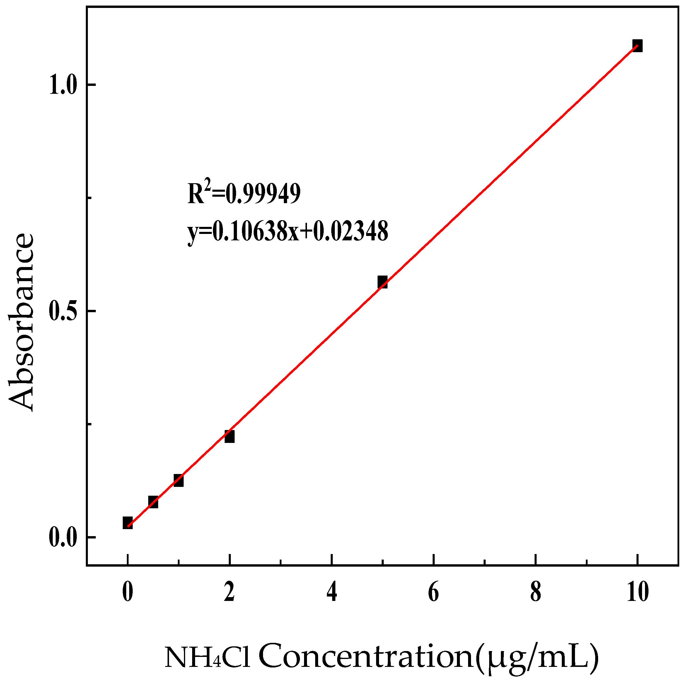
2.5.1. NH4+ Standard Curve

After constant potential electrolysis, collect the electrolyte from the cathode and use the indophenol blue method to detect the ammonium ions and deduce the ammonia content.
Reagent (1): Add 5 g of salicylic acid and 5 g of sodium citrate into 100 mL of 1 mol/L NaOH. Reagent (2): Add 0.5 mL of NaClO (8% effective chlorine) to 19.5 mL of deionized water (diluted 40 times). Reagent (3): Fix 0.5 g C5FeN6Na2O in 50 mL of deionized water.
Configuration of a standard solution: Firstly, dry a certain amount of ammonium chloride in an oven. Take 0.01 g of ammonium chloride and add it to 100 mL of deionized water to obtain the ammonium chloride solution. Mix 0 μL, 125 μL, 250 μL, 500 μL, 1250 μL, or 2500 μL of ammonium chloride solution with 0.1 mol/L of KOH and add to the 25 mL cuvette and mix it well to obtain a series of standard solutions.
The specific steps of the calibration experiment were as follows: First, 2 mL of standard solution was added to 2 mL of reagent (1), then 1 mL of reagent (2) and 0.2 mL of reagent (3) were added to the standard solution and mixed in a 10 mL centrifuge tube. After the mixed solution was placed at room temperature and reacted for 2 h, the corresponding absorbance (maximum λ = 655 nm) was measured by UV–visible spectrophotometry, and the standard relationship curve of NH4+ concentration and absorbance was obtained. The standard curve equation was y = 0.10638 x + 0.02348 ,   R 2 = 0.99949 , as shown in Figure 1. A consistent method was used in this experiment to detect the NH4+ concentration of the electrolyte in the cathode chamber.

2.5.2. Calculation of Ammonia Yield (Mmol·H−1·Mgcat−1)

In Equation (1):
C N H 3 = C NH 4 + ×   V ×   A 53.5 × B
where CNH4+ is the ammonium ion concentration (μg/mL) derived from the standard equation, A is the electrolyte dilution in the cathode chamber (20 in this experiment), V is the volume of the electrolyte (50 in this experiment), B is the catalyst loading (0.4 mg·cm2 in this experiment), and 53.5 is the molecular weight of ammonium chloride.

2.5.3. Faraday Efficiency Calculation (%)

In Equation (2):
FE = F   ×   8   ×   B   × C NH 3 Q   ×   10 6 × 100 %
where F is the Faraday constant (96,500 C·mol−1) and Q is the number of charges consumed by the catalyst in the experiment.

3. Results and Discussion

3.1. Catalyst Characterization Experiments

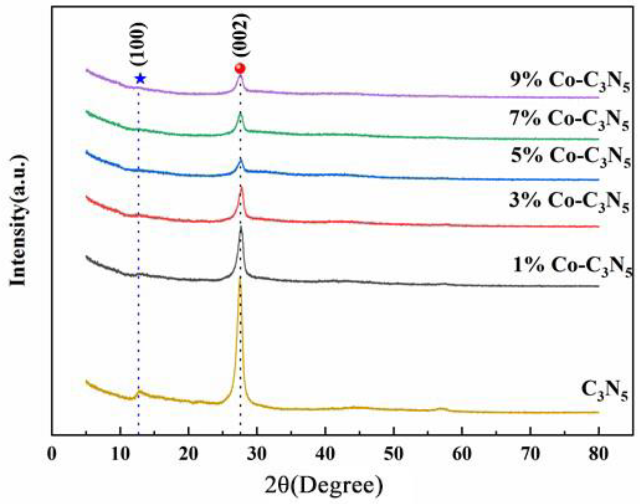
3.1.1. X-ray Diffraction, XRD

In order to clarify the crystal structure in the composites, the synthesized samples were analyzed by XRD. The results obtained from its XRD analysis are shown in Figure 2. In the C3N5 and low-cobalt-doped Co-C3N5 composites, their XRD spectra show two raised characteristic peaks at 2θ = 12.7° and 27.4°, the former belonging to the (100) plane, and the other peak belonging to the (002) plane, which is the plane formed by the stacking of aryl rings in the C3N5, indicating a good match with JCPDS 87-1526 [17]. Although the XRD patterns of the (002) plane diffraction peaks confirmed that all cobalt-doped C3N5 products have graphitized CN structures [18], the doping of Co affects the intensity of the characteristic peaks, and the intensities of the two characteristic peaks gradually diminish with an increase in cobalt element doping. Although the catalyst was doped with cobalt elements for calcination but no diffraction peaks were observed for cobalt, it was presumed that the content of cobalt elements in the catalyst was relatively small or the crystallinity was too low to reach the detection limit of the equipment, resulting in the scanning process being difficult to detect. Other detection methods need to be used for further detection. The most important component of the sample is still C3N5.

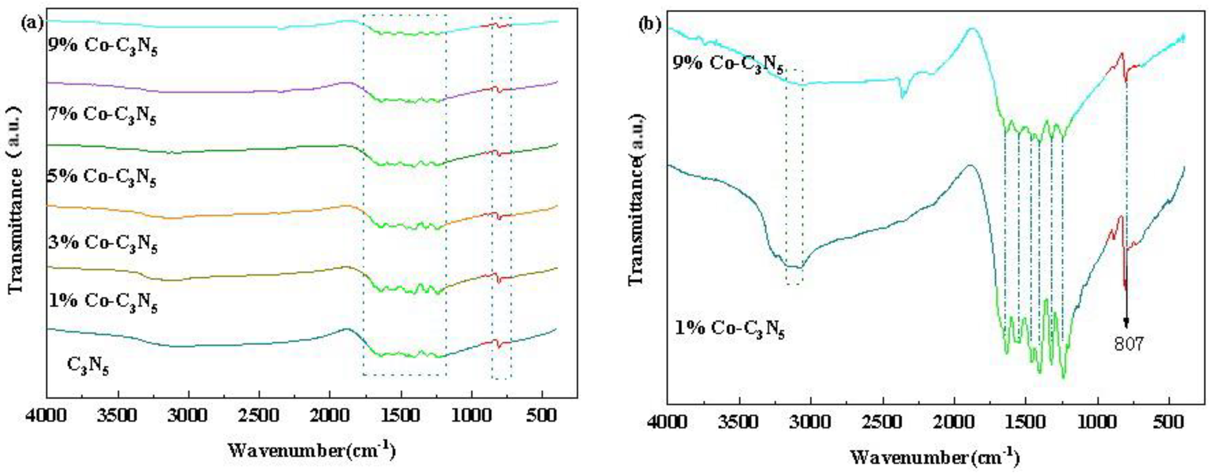
3.1.2. Fourier Transform Infrared, FTIR

In order to determine the variation in the effect of the cobalt elemental doping ratio on the functional groups during the synthesis of the materials, the infrared spectrograms obtained from the materials synthesized with different cobalt doping ratios were analyzed. Figure 3a,b show the spectrograms of all the materials at the scanning wavelengths of 400–4000 cm−1. The FT-IR spectrograms obtained for these prepared samples are generally similar, but there are some differences, and the intensity of the peaks appears to vary in some magnitude. The bands between 1250 and 1650 cm−1 in the spectrograms originate from the typical stretching vibrations of the heterocyclic CN unit [19], the peaks around 810 cm−1 are related to the vibrations of the triazine unit, the absorption peaks around 1400 cm−1 are related to the stretching vibrations of the triazole ring [20,21], and the absorption peaks in the range of 1200–1700 cm−1 include the absorption peaks at 1320 and 1240 cm−1, which are part of the stretching modes of the C-N heterocyclic ring with a nitrogenated carbon wall structure [22,23]. Moreover, the peak near 3100 cm−1 comes from the -NH stretching vibration on the CN surface [19,24] and weakens with a further increase in Co doping. This implies that the -NH group on the catalyst surface may be an important site for bonding with Co, which favors the performance of the catalyst [17].

3.1.3. X-ray Photoelectron Spectroscopy, XPS

In order to understand the distribution of elemental valence and covalent bonding in the catalyst, XPS full-spectrum scanning and fine-spectrum analysis of C3N5 and cobalt-doped C3N5 were performed, and the results of the full spectrum are shown in Figure 4a,b. According to the full spectrum analysis, it can be seen that the three elements C, N, and O exist in C3N5. The four elements C, N, O, and Co exist in Co-C3N5 at the same time, which indicates that cobalt was successfully doped on the C3N5 catalysts. But the cobalt content is low, resulting in the Co2p peaks in the full spectrum also being weak. In order to be more precise about the valence of each element, the fine spectra were analyzed for 1% Co-C3N5, 3% Co-C3N5, and 9% Co-C3N5. The C1s spectra shown in Figure 4c have two characteristic peaks at binding energies of 284.8 eV and 287.9 eV. The characteristic peak at 284.8 eV has the bonding form of C-C/C=C, and the other characteristic peak formation originates from the sp2 orbital hybridization of N-C=N [25]. The peak intensity of C-C/C=C for the 9% Co-C3N5 catalyst is higher than that of 1% Co-C3N5 and 3% Co-C3N5, as can also be seen in Figure 4. In Figure 4d, it can be observed that Co-C3N5 divides the N1s spectra into two distinctive characteristic peaks, which are pyridine nitrogen at 398.6 eV (CH-N=C) and pyrrole nitrogen at 399.9 eV (C-NH-C) [26]. There is a plasma weak signal located at N1s 404.1 eV attributed to the π-electrons in the CN heterocycle [27]. As can be seen from the Co2p fine spectrum (Figure 4e), there are two hybridization orbitals of cobalt in the catalyst: the Co2p1/2 orbitals at 802.7 eV and the Co2p3/2 orbitals at 781.2 eV [28]. In addition, there are two distinct satellite peaks at the binding energies of 796.6 eV and 789.3 eV, which are peaks due to the oscillatory excitation of high-spin divalent cobalt ions [29]. The chemical determination of oxygen has an important influence on the electrocatalytic properties of cobalt-doped C3N5, and we used X-ray photoelectron spectroscopy (XPS) to systematically determine the oxidation state of our samples, which, in reference to SV Trukhanov et al. (2010), showed that complex transition-metal compounds usually have an excess or defect of oxygen [30]. In our samples, the presence of oxygen defects may change the precipitation state of cobalt and may also affect its response to the C3N5 substrate. Combined with previous studies that found that the prepared samples may have slight oxygen defects, which can lead to a change in the oxidation state of cobalt and affect the electron transfer process in the electrocatalytic reaction, we suggest that the oxidation state of Co in the Co-C3N5 sample with lower Co loading is still 2+, which is consistent with observations in the literature [31].

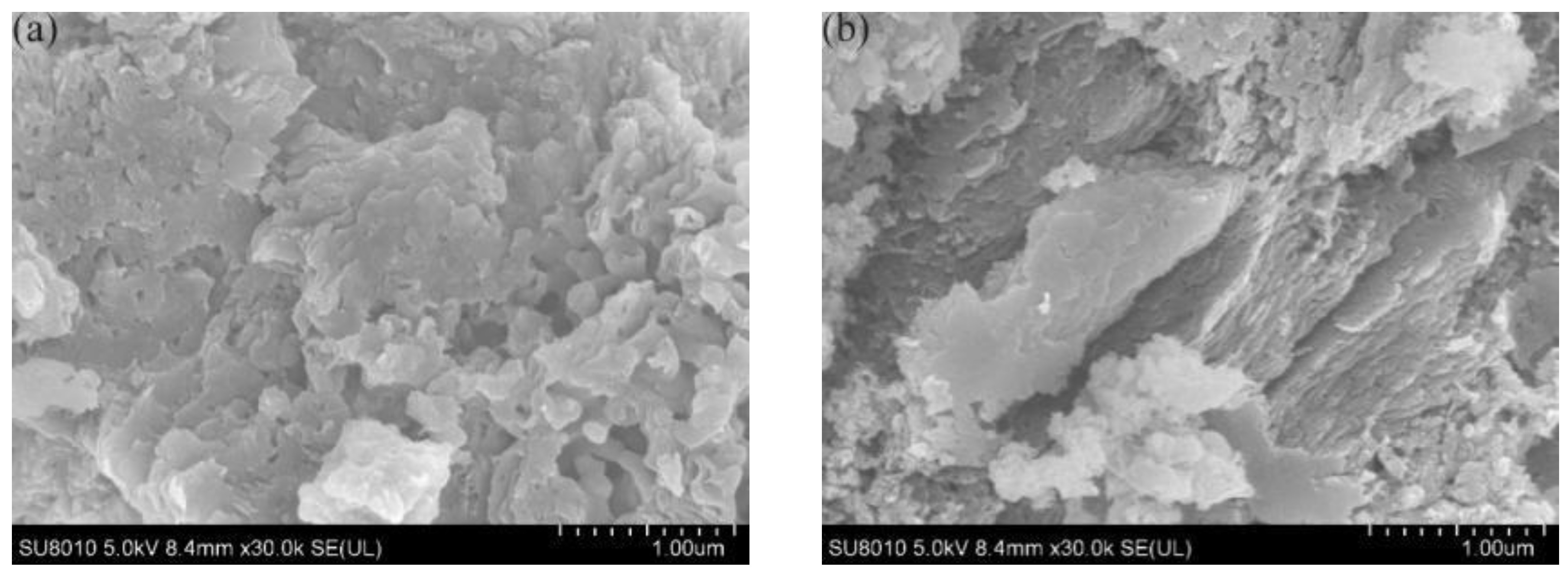
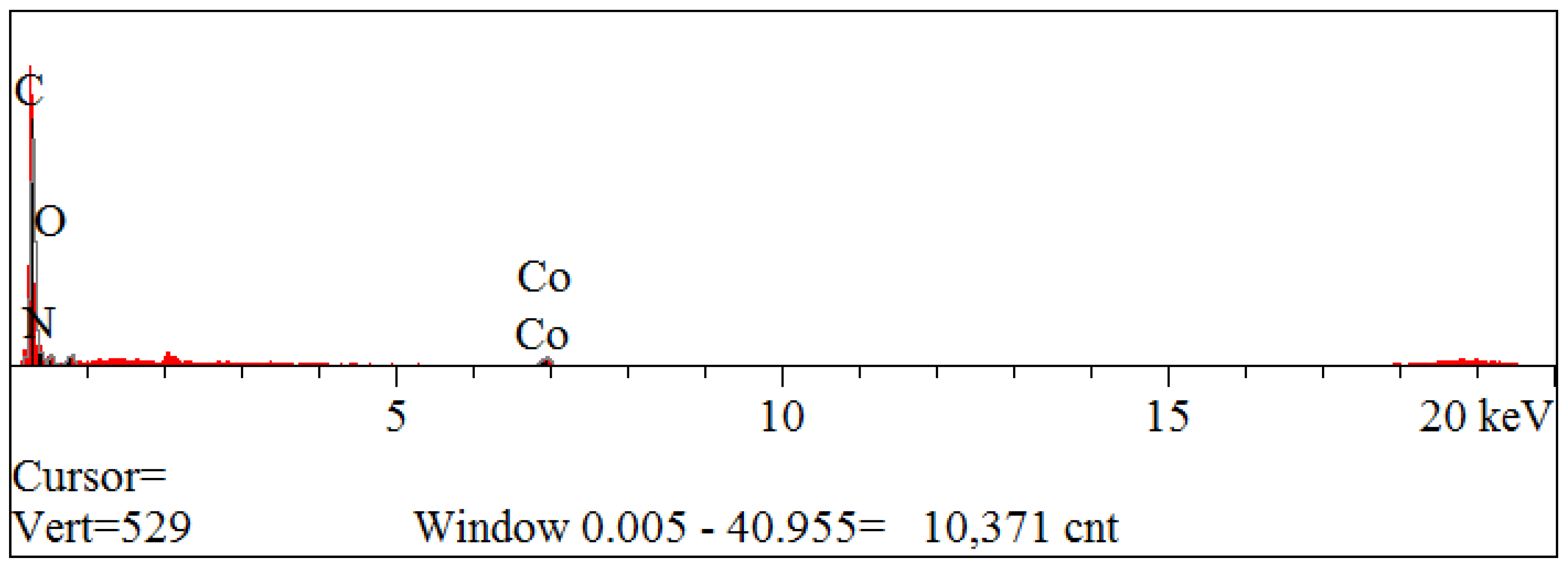
3.1.4. Scanning Electron Microscope and Energy-Dispersive X-ray Spectroscopy, SEM and EDS

In order to observe the difference between the morphology and structure of Co-C3N5 composites and C3N5, this experiment was carried out to observe the effect of the transition metal cobalt on the morphology of the catalysts by the SEM method. Figure 5a shows the C3N5 sample directly generated by the calcination of 3-amino-1,2,4triazole, from which it can be seen that the C3N5 surface shows a lamellar and flaky structure and is stacked together. Figure 5b shows the Co-C3N5 composites. The main body of its surface structure is still a large number of lamellar structures stacked together, but the flaky structure decreases and the surface of the material appears to be many fine particles. These irregular particle stacking aggregates are attached to the surface of the catalyst, and the observed structural surface of C3N5 shows a large difference. It can be concluded that the cobalt element was doped in the C3N5 material.
In order to prove more conclusively that cobalt was doped on C3N5, the material was analyzed by EDS to detect the elemental substances present in the material and was compared with the material before doping, and the detected results are shown below in Figure 5c and Figure 6 as well as in Table 1. Cobalt can be observed in the above chart, indicating that the composites have been successfully prepared and cobalt has been doped on C3N5.
Figure 4. (a) XPS full spectrum of C3N5, 1% Co-C3N5 and 3% Co-C3N5; (b) XPS full spectrum of 5% Co-C3N5, 7% Co-C3N5 and 9% Co-C3N5; (c) C1s spectrum of 1% Co-C3N5, 3% Co-C3N5 and 9% Co-C3N5; (d) N1s spectrum of 1% Co-C3N5, 3% Co-C3N5 and 9% Co-C3N5; (e) Co2p spectrum of 1% Co-C3N5, 3% Co-C3N5 and 9% Co-C3N5.
Coatings 14 01327 g004
Figure 5. (a) Scanning electron microscope image of C3N5; (b) scanning electron microscope image of Co-C3N5; (c) copper element distribution of Co-C3N5.
Coatings 14 01327 g005aCoatings 14 01327 g005b
Figure 6. 9% Co-C3N5 energy-dispersive spectrum.
Coatings 14 01327 g006

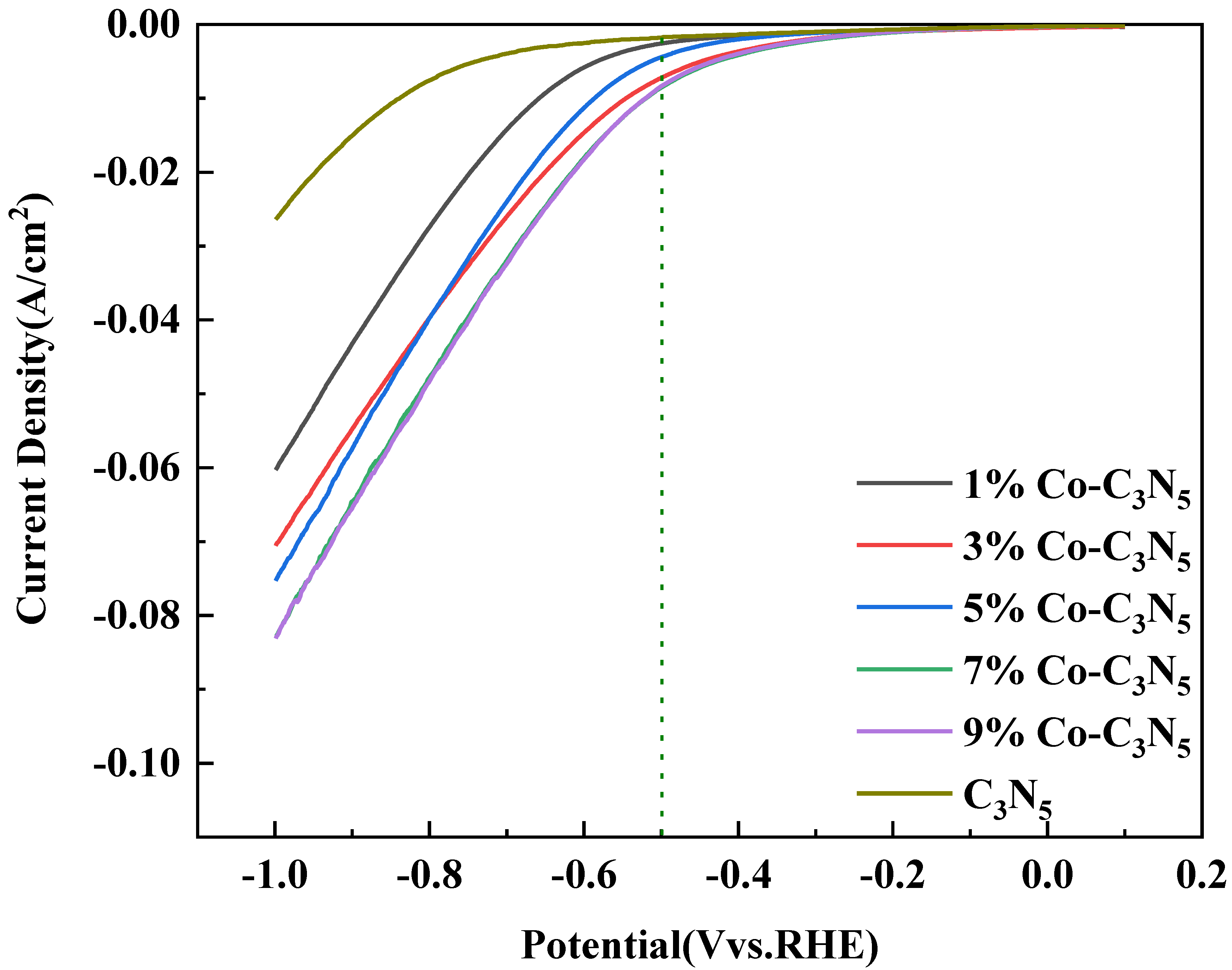
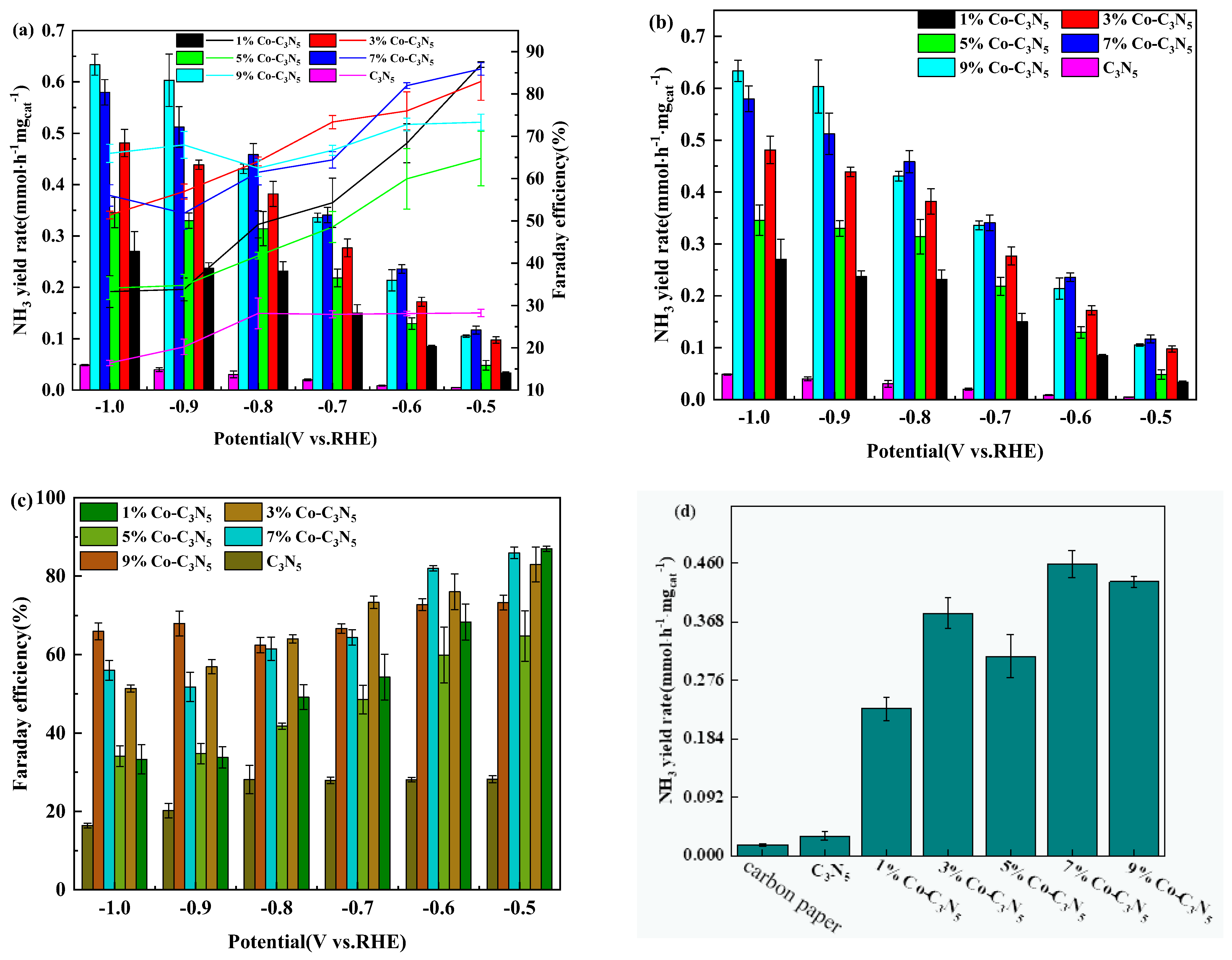
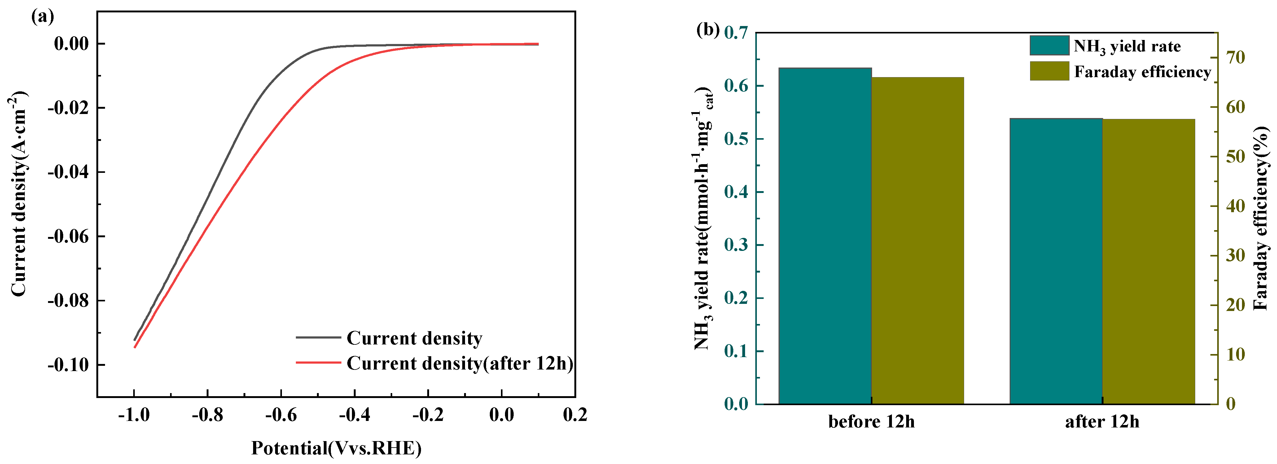
3.2. Co-C3N5 Catalyst Electrochemical Performance Testing Experiments

The synthesized samples obtained from cobalt doping were subjected to 10 CV tests at a scan rate of 10 mV s−1 to initially stabilize the catalyst properties and enter into the activated state before proceeding to the next electrochemical test. The variation in the LSV curves was used to initially determine the potential range of the electrochemical properties of each synthetic material. The variation rule of the Co-C3N5 catalyst on the effect of current density shows a positive correlation. The results are shown in Figure 7. The trend of the electrochemical changes in the measured samples is more obvious below the potential range of −0.5 V vs. RHE, i.e., the catalyst will have reducing activity towards nitrate when the applied potential is less than −0.5 V vs. RHE. Ammonia production efficiency and Faraday efficiency experiments for the electrocatalytic reduction of nitrate were carried out for Co-C3N5 at potential intervals from −0.5 V to −1.0 V vs. RHE. As can be seen in Figure 7, Co-C3N5 passes through higher current density values than C3N5 under the same experimental conditions, indicating that the electrochemical reduction of a single C3N5 is weaker.
After the preliminary determination of the activity range of Co-C3N5, the constant potential electrolysis of nitrate was taken to investigate the effect of the cobalt doping ratio on the catalysts’ performance, such as ammonia production. The electrolysis voltage of each catalyst was −0.5~−1.0 V vs. RHE, and the electrolysis was carried out for a period of 1 h. At the end of the experiment, the electrolyte in the cathode chamber was collected, and the amount of ammonium collected in the electrolyte was calculated by UV spectrophotometry to obtain the ammonia production rate of each group as well as the Faraday’s efficiency of each group. In order to reduce the error in the experimental process, each group of experiments was repeated three times to take the average value as the experimental results. As can be seen in Figure 8a–c, the calculated ammonia yield of C3N5 at −0.5 V vs. RHE potential is 0.0049 mmol∙h−1∙mgcat−1, and that of 1% Co-C3N5 at this potential is 0.0335 mmol∙h−1∙mgcat−1, which is a nearly seven-fold difference in yield. The ammonia yields of 3% Co-C3N5, 5% Co-C3N5, 7% Co-C3N5 and 9% Co-C3N5 at −0.5 V vs. RHE potential were higher than that of 1% Co-C3N5, so it can be concluded that the addition of cobalt can significantly improve the chemical performance of C3N5 catalysts. In addition, it can be found that as the applied voltage increases, i.e., the reduction potential is shifted negatively, the ammonia production rate of each catalyst increases with it. This phenomenon arises because a high voltage provides more electrons to reduce nitrate. The Faraday efficiency in the figure appears as a volcano-like pattern, which is due to the fact that too high an applied reduction voltage creates more HER competition [32]. In this experiment, Co-C3N5 with a 9% doping ratio achieved the maximum ammonia production rate of 0.6335 ± 0.02 mmol∙h−1∙mgcat−1 at −1.0 V vs. RHE (Faraday efficiency at this point was 65.98 ± 2.14%). In the course of the reaction, catalysis was proposed to begin with the one-electron reduction of the Co(II)-NO2 substance. The addition of two protons to the resulting Co(II)-NO2 material will promote the cleavage of the N-O bond with the release of H2O to produce the {CoNO}8 complex [33,34]. Single-electron reduction leads to reactive {CoNO}9 complexes. Upon protonation, Co(II)-HNO (nitro) species are generated [35]. The addition of two electrons and two protons to the nitroxyl adduct would yield the NH2OH intermediate as Co(II)-NH2OH. A two-electron, two-proton reduction forms a Co(II)-NH3 complex. A two-electron, two-proton reduction forms a Co(II)-NH3 complex. With protonation, NH4+ is released [7].
Figure 8d shows the comparative NH3 yields of the catalysts at −0.8 V vs. RHE potential. It can be seen that the ammonia yield of 7% Co-C3N5 is slightly higher than that of 9% Co-C3N5. The corresponding ammonia yields for these two catalysts were 0.4585 ± 0.02 mmol∙h−1∙mgcat−1 and 0.4307 ± 0.01 mmol∙h−1∙mgcat−1. High cobalt doping resulted in lower ammonia yields, suggesting that excessive cobalt metal element doping would be detrimental to the electrochemical process. Presumably, if the cobalt element is over-doped, a metal aggregation or stacking phenomenon will be formed on the surface, which will reduce the active sites on the catalyst surface, thus leading to the reduction performance of the catalyst being reduced.
One of the ways to test the stability of catalyst performance is to conduct multiple cycle tests in electrocatalytic experiments. A well-performing catalyst not only has a relatively strong nitrate reduction capacity but also has the ability to be recycled repeatedly. In order to verify the effect of Co introduction on the reuse of C3N5 catalysts, cyclic electrolysis experiments were carried out at an optimal ammonia production rate potential (−1.0 V vs. RHE) to evaluate whether 9% Co-C3N5 could be reused in the electrolysis process. During the multiple cycling experiments, only the electrolyte in the cathode chamber was replaced before each experiment, and other external factors such as the proton exchange membrane, electrolytic cell, working time, and working electrode were consistently kept unchanged, and the ammonia yield and Faraday’s efficiency in the electrolyte were determined at the end of each experiment. From Figure 9a,b, it can be seen that the change in current density after five repeats of the 9% Co-C3N5 test is small, indicating that the catalyst still has good electrochemical performance after five repeats of the test and can be recycled repeatedly in the reaction. In contrast, the Faraday efficiency and ammonia production rate decreased from the original 58.66 % and 0.558 mmol∙h−1∙mgcat−1 to 51.43 % and 0.468 mmol∙h−1∙mgcat−1 in the cycling of five tests. The decrease, although present but small, can also indicate that the electrochemical performance change is weak, and the catalyst is still able to electrolytically reduce nitrate to NH3 well after five cycle tests.
In addition to being able to be recycled repeatedly, the catalyst also needs to be able to maintain stable operation for a long time. Electrolysis tests were carried out with 9% Co-C3N5 at −1.0 V vs. RHE potential for up to 12 h. The electrochemical performance of the catalysts was determined at the end of the experiment, and the experimental results are shown in Figure 10. From Figure 10a,b, it can be seen that the electrochemical performance of the catalysts after the 12-h electrocatalytic experiment is comparable to that of 12 h ago. There is a possibility that the 9% Co-C3N5 catalyst is activated during the reaction process, which leads to a slight increase in the current density. This indicates that even after 12 h of operation, the catalyst still has a good electrochemical performance and is able to carry out electrochemical action in the electrolyte for a long time. The Faraday efficiency and ammonia production rate of the catalyst were re-tested after 12 h of action, and it was found that both of them were slightly lower than the ammonia production rate and Faraday efficiency from 12 h previous. The ammonia production rate was reduced from 0.6335 mmol∙h−1∙mgcat−1 to 0.5383 mmol∙h−1∙mgcat−1, and the Faraday efficiency was reduced from 65.98% to 57.55%. This indicates that the catalyst can still operate relatively stably for a long time after 12 h of current action.

4. Conclusions

In summary, C3N5 was first synthesized by pyrolysis in a muffle furnace using 3-amino-1,2,4 triazole material. Then, by varying the mass ratio of cobalt chloride to C3N5 and going through the steps of stirring and ultrasonic shaking, 1% Co-C3N5, 3% Co-C3N5, 5% Co-C3N5, 7% Co-C3N5, and 9% Co-C3N5 were finally synthesized. Electrocatalytic reduction experiments were carried out on the synthesized catalysts in an H-type electrolytic cell and CHI660E electrochemical workstation to convert the NH3 yield using the indophenol blue method and to determine the electrochemical performance of the catalysts. Firstly, the potential interval in which the catalyst possessed electrocatalytic nitrate activity was initially determined from the linear voltametric curves in the electrochemical tests, and the potential range in which the catalyst showed a significant trend was obtained from the LSV diagram.
When a 9% Co-C3N5 catalyst was used as the working electrode, the ammonia production rate was 0.633 ± 0.02 mmol∙h−1∙mgcat−1 at −1.0 V vs. RHE potential for 1 h in a mixed electrolytic solution of 0.1 mol/L KNO3 and 0.1 mol/L KOH, which resulted in a Faraday efficiency of 65.98 ± 2.14%. A comparison with the catalyst C3N5 revealed that the ammonia production rate and Faraday efficiency of the C3N5 catalyst at −1.0 V vs. RHE potential were 0.049 mmol∙h−1∙mgcat−1 and 16.41%, respectively. The ammonia production rate of the C3N5 catalyst was nearly 13-fold worse than the 9% Co-C3N5. This suggests that Co can improve the Faraday efficiency and ammonia yield in the electrocatalytic reduction of NO3. The 9% Co-C3N5 showed a small change in current density after five trials and a decrease in ammonia yield of about 12% after five repetitions of the experiment. This indicates that 9% Co-C3N5 can be recycled and work stably in electrocatalytic reactions. The characterization results indicate that the -NH groups on the catalyst surface may be important sites for bonding with Co, which have a strong synergistic effect in promoting ammonia synthesis during the electrocatalytic nitrate reduction process.
Overall, our work introduces non-precious metal elements to regulate the electronic structure and active sites of materials, providing innovative attempts for the preparation of efficient non-precious metal electrocatalysts and demonstrating industrial application potential. Our findings may also be useful in other fields. In our future work, we will further enhance the catalytic activity of the catalysts by introducing other non-precious metals.

Author Contributions

Conceptualization, B.L.; Methodology, B.L.; Software, B.L. and Y.W.; Validation, Y.W.; Formal analysis, J.H.; Investigation, J.H.; Resources, W.D., X.Z. and L.F.; Data curation, W.D. and X.Z.; Writing—original draft, B.L. and Y.W.; Writing—review & editing, J.D., L.F. and R.L. (Runhua Liao); Visualization, R.L. (Runrun Li), Y.H. and R.L. (Runhua Liao); Supervision, Y.H., J.D. and R.L. (Runhua Liao); Project administration, L.F. and R.L. (Runhua Liao); Funding acquisition, R.L. (Runhua Liao). All authors have read and agreed to the published version of the manuscript.

Funding

Jingdezhen Municipal Science and Technology Program Projects (20234NY006); Jingdezhen Municipal Science and Technology Program Projects (20234SF009); Jingdezhen Ceramic University Graduate Student Innovation and Entrepreneurship Program (JYC2023412).

Institutional Review Board Statement

Not applicable.

Informed Consent Statement

Not applicable.

Data Availability Statement

All data generated during this study are presented in the article.

Conflicts of Interest

The authors declare that they have no conflicts of interest.

References

  1. Xiong, Y.; Wang, Y.; Zhou, J.; Liu, F.; Hao, F.; Fan, Z. Electrochemical nitrate reduction: Ammonia synthesis and the beyond. Adv. Mater. 2024, 36, 2304021. [Google Scholar] [CrossRef] [PubMed]
  2. Yu, J. Surface Modification of Porous Graphitic Carbon Nitride and Its Electrocatalytic Ammonia Synthesis Performance. Master’s Thesis, Yanshan University, Qinhuangdao, China, 2022. [Google Scholar]
  3. Gao, J.; Jiang, B.; Ni, C.; Qi, Y.; Zhang, Y.; Oturan, N.; Oturan, M.A. Non-precious Co3O4-TiO2/Ti cathode based electrocatalytic nitrate reduction: Preparation, performance and mechanism. Appl. Catal. B Environ. 2019, 254, 391–402. [Google Scholar] [CrossRef]
  4. Tarascon, J.M.; Armand, M. Issues and challenges facing rechargeable lithium batteries. Nature 2001, 414, 359–367. [Google Scholar] [CrossRef] [PubMed]
  5. Chen, D.; Pan, L.; Pei, P.; Song, X.; Ren, P.; Zhang, L. Cobalt-based oxygen electrocatalysts for zinc-air batteries: Recent progress, challenges, and perspectives. Nano Res. 2022, 15, 5038–5063. [Google Scholar] [CrossRef]
  6. Cheng, S.H.; Su, Y.O. Electrocatalysis of nitric oxide reduction by water-soluble cobalt porphyrin. Spectral and electrochemical studies. Inorg. Chem. 1994, 33, 5847–5854. [Google Scholar] [CrossRef]
  7. Guo, Y.; Stroka, J.R.; Kandemir, B.; Dickerson, C.E.; Bren, K.L. Cobalt metallopeptide electrocatalyst for the selective reduction of nitrite to ammonium. J. Am. Chem. Soc. 2018, 140, 16888–16892. [Google Scholar] [CrossRef]
  8. Wang, J.; Cai, C.; Wang, Y.; Yang, X.; Wu, D.; Zhu, Y.; Li, M.; Gu, M.; Shao, M. Electrocatalytic reduction of nitrate to ammonia on low-cost ultrathin CoOx nanosheets. ACS Catal. 2021, 11, 15135–15140. [Google Scholar] [CrossRef]
  9. Hong, Q.L.; Zhou, J.; Zhai, Q.G.; Jiang, Y.C.; Hu, M.C.; Xiao, X.; Li, S.N.; Chen, Y. Cobalt phosphide nanorings towards efficient electrocatalytic nitrate reduction to ammonia. Chem. Commun. 2021, 57, 11621–11624. [Google Scholar] [CrossRef]
  10. Deng, X.; Yang, Y.; Wang, L.; Fu, X.Z.; Luo, J.L. Metallic Co nanoarray catalyzes selective NH3 production from electrochemical nitrate reduction at current densities exceeding 2 A cm−2. Adv. Sci. 2021, 8, 2004523. [Google Scholar] [CrossRef]
  11. Wang, J.; Feng, T.; Chen, J.; Ramalingam, V.; Li, Z.; Kabtamu, D.M.; He, J.H.; Fang, X. Electrocatalytic nitrate/nitrite reduction to ammonia synthesis using metal nanocatalysts and bio-inspired metalloenzymes. Nano Energy 2021, 86, 106088. [Google Scholar] [CrossRef]
  12. Xu, H.; Ci, S.; Ding, Y.; Wang, G.; Wen, Z. Recent advances in precious metal-free bifunctional catalysts for electrochemical conversion systems. J. Mater. Chem. A 2019, 7, 8006–8029. [Google Scholar] [CrossRef]
  13. Sun, X.W.; Bai, J.; Li, C.P.; Liang, H.O.; Xu, T.; Sun, W.Y. Modification strategy and application of cobalt-based electrode materials. Acta Mater. Compos. Sin. 2023, 40, 2550–2565. [Google Scholar] [CrossRef]
  14. Agayev, F.G.; Trukhanov, S.V.; Trukhanov, A.V.; Jabarov, S.H.; Ayyubova, G.S.; Mirzayev, M.N.; Trukhanova, E.L.; Vinnik, D.A.; Kozlovskiy, A.L.; Zdorovets, M.V.; et al. Study of structural features and thermal properties of barium hexaferrite upon indium doping. J. Therm. Anal. Calor. 2022, 147, 14107–14114. [Google Scholar] [CrossRef]
  15. Wang, S.; Chen, S.; Ma, L.; Zapien, J.A. Recent progress in cobalt-based carbon materials as oxygen electrocatalysts for zinc-air battery applications. Mater. Today Energy 2021, 20, 100659. [Google Scholar] [CrossRef]
  16. Trukhanov, A.V.; Panina, L.V.; Trukhanov, S.V.; Kostishyn, V.G.; Turchenko, V.A.; Vinnik, D.A.; Zubar, T.I.; Yakovenko, E.S.; Macuy, L.Y.; Trukhanova, E.L. Critical influence of different diamagnetic ions on electromagnetic properties of BaFe12O19. Ceram Int. 2018, 44, 13520–13529. [Google Scholar] [CrossRef]
  17. He, P.; Gu, C.; Tang, B.; Zhou, Y.; Gan, M.; Zhu, J. Expeditious degradation of SMX by high-valent cobalt-oxo species derived from cobalt-doped C3N5-activated peroxymonosulfate with the assistance of visible light. Sep. Purif. Technol. 2022, 301, 122009. [Google Scholar] [CrossRef]
  18. Li, M.; Lu, Q.; Liu, M.; Yin, P.; Wu, C.; Li, H.; Zhang, Y.; Yao, S. Photoinduced charge separation via the double-electron transfer mechanism in nitrogen vacancies g-C3N5/BiOBr for the photoelectrochemical nitrogen reduction. ACS Appl. Mater. Interfaces 2020, 12, 38266–38274. [Google Scholar] [CrossRef]
  19. Liu, T.; Yang, G.; Wang, W.; Wang, C.; Wang, M.; Sun, X.; Xu, P.; Zhang, J. Preparation of C3N5 nanosheets with enhanced performance in photocatalytic methylene blue (MB) degradation and H2-evolution from water splitting. Environ. Res. 2020, 188, 109741. [Google Scholar] [CrossRef]
  20. Hu, X.; Zeng, X.; Liu, Y.; Lu, J.; Yuan, S.; Yin, Y.; Hu, J.; McCarthy, D.T.; Zhang, X. Nano-layer based 1T-rich MoS2/g-C3N4 co-catalyst system for enhanced photocatalytic and photoelectrochemical activity. Appl. Catal. B Environ. 2020, 268, 118466. [Google Scholar] [CrossRef]
  21. Wei, W.; Gong, H.; Sheng, L.; Wu, H.; Zhu, S.; Feng, L.; Li, X.; You, W. Highly efficient photocatalytic activity and mechanism of novel Er3+ and Tb3+ co-doped BiOBr/g-C3N5 towards sulfamethoxazole degradation. Ceram. Int. 2021, 47, 24062–24072. [Google Scholar] [CrossRef]
  22. Kim, I.Y.; Kim, S.; Jin, X.; Premkumar, S.; Chandra, G.; Lee, N.S.; Mane, G.P.; Hwang, S.J.; Umapathy, S.; Vinu, A. Ordered Mesoporous C3N5 with a Combined Triazole and Triazine Framework and Its Graphene Hybrids for the Oxygen Reduction Reaction (ORR). Angew. Chem. 2018, 130, 17381–17386. [Google Scholar] [CrossRef]
  23. Sathish, C.I.; Premkumar, S.; Chu, X.; Yu, X.; Breese, M.B.; Al-Abri, M.; Al-Muhtaseb, A.A.; Karakoti, A.; Yi, J.; Vinu, A. Microporous Carbon Nitride (C3N5.4) with Tetrazine based Molecular Structure for Efficient Adsorption of CO2 and Water. Angew. Chem. 2021, 133, 21412–21419. [Google Scholar] [CrossRef]
  24. Chen, W.; He, Z.C.; Huang, G.B.; Wu, C.L.; Chen, W.F.; Liu, X.H. Direct Z-scheme 2D/2D MnIn2S4/g-C3N4 architectures with highly efficient photocatalytic activities towards treatment of pharmaceutical wastewater and hydrogen evolution. Chem. Eng. J. 2019, 359, 244–253. [Google Scholar] [CrossRef]
  25. Wang, B. The Study on the Photocatalytic Activity of ZnO/C3N5 and B-C3N5. Master’s Thesis, Shanxi University, Taiyuan, China, 2021. [Google Scholar]
  26. Gong, Y.N.; Jiao, L.; Qian, Y.Y.; Pan, C.Y.; Zheng, L.R.; Cai, X.C.; Liu, B.; Yu, S.H.; Jiang, H.L. Regulating the coordination environment of MOF-templated single-atom nickel electrocatalysts for boosting CO2 reduction. Angew. Chem. Int. Ed. 2020, 59, 2705–2709. [Google Scholar] [CrossRef]
  27. Mane, G.P.; Talapaneni, S.N.; Lakhi, K.S.; Ilbeygi, H.; Ravon, U.; Al-Bahily, K.; Mori, T.; Park, D.H.; Vinu, A. Highly ordered nitrogen-rich mesoporous carbon nitrides and their superior performance for sensing and photocatalytic hydrogen generation. Angew. Chem. Int. Ed. 2017, 56, 8481–8485. [Google Scholar] [CrossRef]
  28. Song, T.L.; Zou, M.S.; Lu, D.F. Textbook of X-ray Photoelectron Spectroscopy Data Analysis; Beijing Institute of Technology Press: Beijing, China, 2022. [Google Scholar]
  29. Yang, M.; Wu, D.; Cheng, D. Biomass-derived porous carbon supported CoCoO yolk-shell nanoparticles as enhanced multifunctional electrocatalysts. Int. J. Hydrogen Energy 2019, 44, 6525–6534. [Google Scholar] [CrossRef]
  30. Trukhanov, S.V.; Trukhanov, A.V.; Vasiliev, A.N.; Szymczak, H. Frustrated exchange interactions formation at low temperatures and high hydrostatic pressures in La0.70Sr0.30MnO2.85. J. Exp. Theor. Phys. 2010, 111, 209–214. [Google Scholar] [CrossRef]
  31. Huang, P.; Huang, J.; Pantovich, S.A.; Carl, A.D.; Fenton, T.G.; Caputo, C.A.; Grimm, R.L.; Frenkel, A.I.; Li, G. Selective CO2 reduction catalyzed by single cobalt sites on carbon nitride under visible-light irradiation. J. Am. Chem. Soc. 2018, 140, 16042–16047. [Google Scholar] [CrossRef]
  32. Shi, Y.B. Preparation of Cobalt and Iron-Based Electrocatalysts and Their Application in Electrochemical Ammonia Synthesis. Master’s Thesis, Dalian University of Technology, Dalian, China, 2022. [Google Scholar]
  33. Kozhukh, J.; Lippard, S.J. Influence of tetraazamacrocyclic ligands on the nitric oxide reactivity of their cobalt (II) complexes. J. Am. Chem. Soc. 2012, 134, 11120–11123. [Google Scholar] [CrossRef]
  34. Rhine, M.A.; Rodrigues, A.V.; Urbauer, R.J.; Urbauer, J.L.; Stemmler, T.L.; Harrop, T.C. Proton-induced reactivity of NO from a {CoNO}8 complex. J. Am. Chem. Soc. 2014, 136, 12560–12563. [Google Scholar] [CrossRef]
  35. Walter, M.R.; Dzul, S.P.; Rodrigues, A.V.; Stemmler, T.L.; Telser, J.; Conradie, J.; Ghosh, A.; Harrop, T.C. Synthesis of CoII–NOcomplexes and their reactivity as a source of nitroxyl. J. Am. Chem. Soc. 2016, 138, 12459–12471. [Google Scholar] [CrossRef]
Figure 1. NH4+ standard mass concentration profile.
Coatings 14 01327 g001
Figure 2. XRD diffractograms of C3N5 and Co-C3N5 for each doping ratio.
Coatings 14 01327 g002
Figure 3. (a) FT-IR comparison between C3N5 and composites; (b) T-IR magnification of both 1% Co-C3N5 and 9% Co-C3N5.
Coatings 14 01327 g003
Figure 7. LSV plot of catalysts possessing electrocatalytic nitrate activity in electrolytes.
Coatings 14 01327 g007
Figure 8. (a) Plot of NH3 yield rate and Faraday efficiency of catalysts at −0.5~−1.0V vs. RHE potentials; (b) comparison of NH3 yield rate of catalysts; (c) comparison of Faraday efficiency of catalysts; (d) NH3 yield rate of catalysts at −0.8 V vs. RHE potentials.
Coatings 14 01327 g008
Figure 9. (a) Plot of NH3 yield rate and Faraday efficiency of 9% Co-C3N5 at −1.0 V vs. RHE potential cycling test repeated 5 times; (b) Plot of LSV of 9% Co-C3N5 at −1.0 V vs. RHE potential test repeated 5 times.
Coatings 14 01327 g009
Figure 10. (a) Comparison of LSV before and after 12 h of electrolysis of 9% Co-C3N5 at −1.0 V vs. RHE potential; (b) Comparison of NH3 yield rate and Faraday efficiency before and after 12 h of electrolysis of 9% Co-C3N5 at −1.0 V vs. RHE potential.
Coatings 14 01327 g010
Table 1. 9% Co-C3N5 atomic-scale diagrams.
Elt.Intensity
(c/s)
Atomic
%
Conc.Units
C326.1860.36353.094wt.%
N15.2025.14525.792wt.%
O17.8913.17715.440wt.%
Co23.311.3155.674wt.%
100.000100.000wt.%Total
Disclaimer/Publisher’s Note: The statements, opinions and data contained in all publications are solely those of the individual author(s) and contributor(s) and not of MDPI and/or the editor(s). MDPI and/or the editor(s) disclaim responsibility for any injury to people or property resulting from any ideas, methods, instructions or products referred to in the content.

