Article

Metal Ions’ Dynamic Effect on Metal-Assisted Catalyzed Etching of Silicon in Acid Solution

Key Laboratory of Hubei Province for Coal Conversion and New Carbon Materials, School of Chemistry and Chemical Engineering, Wuhan University of Science and Technology, Wuhan 430081, China
*
Author to whom correspondence should be addressed.
These authors contributed equally to this work.
Coatings 2024, 14(11), 1405; https://doi.org/10.3390/coatings14111405
Submission received: 29 September 2024 / Revised: 24 October 2024 / Accepted: 31 October 2024 / Published: 5 November 2024
(This article belongs to the Special Issue Coatings as Key Materials in Catalytic Applications)

Abstract

:
Metal-assisted catalyzed etching (MACE) technology is convenient and efficient for fabricating large-area silicon nanowires at room temperature. However, the mechanism requires further exploration, particularly the dynamic effect of various ions in the acid-etching solution. This paper investigated the MACE of silicon wafers predeposited with metal nanofilms in an HF-M(NO3)x-H2O etching solution (where M(NO3)x is the nitrate of the fourth-period elements of the periodic table). The oxidizing ability of Fe3+ and NO3 was demonstrated, and the dynamic influence of metal ions on the etching process was discussed. The results show that the MACE of silicon can be realized in various HF-M(NO3)x-H2O etching solutions, such as KNO3, Al(NO3)3, Cr(NO3)3, Mn(NO3)2, Ni(NO3)2, Co(NO3)2, HNO3, and Ca(NO3)2. It is confirmed that the concentration and type of cations in the etching solution affect the etching rate and morphology of silicon. Fe3+ and NO3 act as oxidants in catalytic etching. The fastest etching rate is about 5~6 μm/h in Ni(NO3)2, Co(NO3)2, and Ca(NO3)2 etching solutions. However, a high concentration of K+ hinders silicon etching. This study expands the application of MACE etching solution systems.

1. Introduction

Silicon nanowires (SiNWs) have attracted widespread attention in the scientific community in recent decades because of their special physical and chemical properties [1,2,3,4,5,6]. There are various methods for synthesizing SiNWs. In 1996, hydrothermal technology was first used to prepare porous silicon [7,8]. The reactor was filled with the HF-Fe(NO3)3-H2O solution and heated by a thermostat to provide high temperature and high pressure to promote the reaction. This hydrothermal technology enables the preparation of porous silicon without an external electric power supply. However, this method requires closed containers like autoclaves. In 2005, K.Q. Peng deposited a Ag or Au nanoparticle layer by electroless deposition on the surface of the silicon wafer, immersed the processed silicon wafer in an HF-Fe(NO3)3-H2O solution at room temperature for half an hour, and successfully synthesized large-area SiNWs using metal-assisted catalyzed etching (MACE), which is more orderly [9]. In addition, Peng studied the mechanism of MACE and explained the flow of electrons and holes in the oxidation–reduction etching process of silicon driven by galvanic cells based on band bending theory [9,10,11]. The contact interface between noble metal particles and silicon can be considered a typical metal–semiconductor contact.
The technology generally adopts a two-step method to prepare nanosilicon by MACE in a liquid system. Firstly, the surface of the cleaned silicon wafer is coated with a noble Ag or Au nanoparticle layer [12,13,14,15,16,17,18,19]. Secondly, the noble-metal-coated silicon wafer is immersed in an etching solution containing HF and an oxidant. The currently reported etching solution systems include HF-H2O2-H2O solution and HF-Fe(NO3)3-H2O solution. It is believed that the above-mentioned electroless deposition of the metal nanoparticle layer and MACE of silicon are both localized microelectrochemical redox processes, including the cathode and anode reactions [20]. Taking the electroless deposition of the silver nanoparticle layer on the silicon wafer surface as an example, the first step of MACE in the liquid system, when the clean silicon wafer is immersed in HF-AgNO3-H2O solution, Ag+ is oxidation, which injects holes into adjacent silicon to gain electrons, which are reduced to Ag that gradually collects on the surface of the silicon wafer to form a uniform nanoparticle layer. The silicon injected with holes is oxidized and highly unstable in hydrofluoric acid solution and reacts with hydrofluoric acid to form the soluble H2SiF6 [21,22,23,24]. As the reaction goes on, the silver particles continually grow and accumulate on the surface of the silicon wafer. Finally, the silicon wafer in the plating solution is tightly covered by a uniform film consisting of silver nanoparticles on the surface. The second step of MACE in the liquid system is essentially an electrochemical etching process driven by the galvanic cell. The dispersed Ag nanoparticles deposited on the surface of the silicon wafer combine with the silicon substrate to form a galvanic cell. The galvanic cell can accelerate the etching of the silicon substrate covered by the metal particles, while the uncovered part of the substrate would be retained. Thereby, a neat array of silicon nanowires is formed on the surface. Taking the reaction in the HF-Fe(NO3)3-H2O solution system as an example, with the catalysis of silver nanoparticles, the Fe3+ can inject a hole into the silicon, obtain electrons, and reduce to Fe2+. As with the reaction in the deposition of the silver nanoparticle layer, holes are injected into the silicon atoms covered by the silver nanoparticles, and the silicon atoms are oxidized. Therefore, the location of the silicon atom at the bottom of the silver nanoparticle becomes a small hole into which the silver nanoparticle “sinks”. As the reaction progresses, more Fe3+ ions in the solution inject holes into silicon atoms through the silver particles. The silicon atoms are continually oxidized to SiO2, which reacts with HF to form silicofluoride radical dissolved in solution. The pits at the bottom of the silver nanoparticles continue to deepen, and the silver nanoparticles gradually sink into the interior of the silicon substrate as the pits grow.
However, it is worth noting that the noble Ag nanoparticle layers are not as stable as they are supposed to be, especially when the oxidant is strong, as there is a dynamic equilibrium of deposition and dissolution of the noble metal particle films in the etching solution. Furthermore, various ions lead to a complex reaction equilibrium, as the Fe3+ and the NO3 ions in the etching solution are also oxidizing but neglected. Focusing on these questions, the objective of this work is to verify the role of Fe3+ as the oxidant in the MACE process and to further discuss whether NO3 can inject holes into the silicon substrate as the oxidant in MACE. This work also focuses on the influence of the dynamic effect of metal ions in M(NO3)x on the MACE process to further explore the mechanism of the MACE process, which helps the expansion of the application and building of low-cost and easy-to-operate systems to prepare large-area SiNW arrays.

2. Materials and Methods

One-side-polished single crystalline N-type (100) 2–2.7 Ω·cm silicon wafers were selected and purchased from Beijing General Research Institute for Nonferrous Metals (GRINM). CH3COCH3, C2H5OH, and HF were purchased from Beijing Sinopharm Chemical Reagent Co., Ltd., Beijing, China, and deionized water was prepared. The other chemicals used were purchased from Sigma–Aldrich (St. Louis, MO, USA) and used without further treatment. The silicon wafers were cut into 2 × 2 cm2 and cleaned ultrasonically in deionized (DI) water, CH3COCH3, and C2H5OH for 10 min, respectively. Then, the silicon wafers were rinsed three times with DI water and immersed in H2SO4-H2O2 solution at 80 °C for 30 min. Finally, enough DI water was used to clean the remaining acid on the silicon wafers. The silicon wafers were placed in HF-AgNO3-H2O or HF-AuCl4H-H2O solution for 2 min in a fume cupboard. Then, the silicon wafer was removed and cleaned with DI water, and then transferred into sealed Teflon-lined autoclaves at a temperature of 50 °C for one hour. The total volume of the etching solution used in all the experiments in this paper was 50 mL. The concentration of HF in the etching solution was 4.6 M if not specially stated in this paper. After the reaction, the silicon wafers were taken out, cleaned, and dried with the SiNWs on the surface. The silicon wafers were cut into 1 × 1 cm2, and the cross- and top-sectional morphologies were characterized by a high-resolution field-emission scanning electron microscope (SEM, HITACHI, S-4800, Hitachi of Japan, Tokyo, Japan). SiNWs were scraped off with a razor blade, dispersed ultrasonically in ethanol for 10 min, and then dropped on copper mesh to dry before being characterized by transmission electron microscopy (TEM, JEOL JEM-2100, Japan Electronics, Tokyo, Japan). The crystal composition was investigated by X-ray diffraction (XRD, Cu kα, SmartLab SE, Rigaku, Corporation, Tokyo, Japan).

3. Results and Discussion

3.1. Oxidation Validation of Fe3+ and NO3

Because of the catalysis of Ag (or Au and Pt), neat SiNW array structures were successfully prepared on both P-type and N-type silicon substrates, according to previous research [25,26,27,28]. However, the etching morphology of the P-type and N-type silicon wafers with normal doping levels in the HF-Fe(NO3)3-H2O are almost the same, and the crystal orientations of the SiNW arrays are determined by the crystal orientation of the substrates. Therefore, an N-type (100) silicon wafer with a resistivity of 2.2 Ω·cm was used as the research object, with Ag as the catalyst. First, the cleaned silicon wafers without silver plating were directly immersed in an etching solution consisting of 4.6 M HF and 1.5 M FeCl3 (HF-FeCl3-H2O) and reacted at 50 °C for 30 min. As shown in Figure 1a, a porous layer about 200 nm thick appeared on the surface of the silicon wafer. This indicates that a redox reaction occurred, and a small amount of silicon was dissolved to form a porous layer, which is consistent with the research results of porous silicon. Next, a silver nanoparticle layer was coated on the surface of the cleaned silicon wafer by the electroless deposition technique described above, and the sample was then put into the HF-FeCl3-H2O solution at 50 °C for 30 min. As shown in Figure 1b,c, there was no sign of etching on the silicon wafer surface, but some micro- and nanospheres appeared. The surfaces of the spheres were not smooth and seemed to have some attachments.
According to relevant reports, these spheres may be AgCl. They were formed from silver nanoparticle layers that dissolved into Ag+ and combined with Cl in the system to form AgCl spheres [29,30,31,32]. Then, the sample was soaked in concentrated nitric acid for half an hour. As shown in Figure 1d,e, these small balls still existed and became smoother. It proves that these balls were indeed AgCl balls, and the surface attachments may be silver dissolved in concentrated nitric acid. For further verification, the crystal composition of the samples was characterized by XRD. The clean silicon wafer coated with a silver nanoparticle layer was directly tested. The XRD curve is shown in Figure 1f(a), and only the characteristic peaks of silver appear around 38° and 44.5°. After the silver-plated silicon wafer was immersed in the HF-FeCl3-H2O solution at 50 °C for 30 min, the characteristic peaks of silver (JCPDS#: 41-1402; the grazing incidence angle was 5°) became weak (Figure 1f(b)), indicating that most silver particles had disappeared.
Compared with the standard XRD pattern, several new characteristic peaks corresponded exactly to those of AgCl (JCPDS#: 31-1238; the grazing incidence angle was 5°), indicating that the small balls in the above pictures were AgCl. Although the silver-plated silicon wafers did not become SiNW arrays when immersed into the HF- FeCl3-H2O solution, as was initially expected, this does not prove the inability of Fe3+ to oxidize. It was suspected that the primary reason for the failure of the expected effect was that silver is unstable in the environment of Fe3+ and becomes Ag+ combined with Cl. The results may be different when changing the silver-coated silicon wafer for the gold-coated silicon wafer.
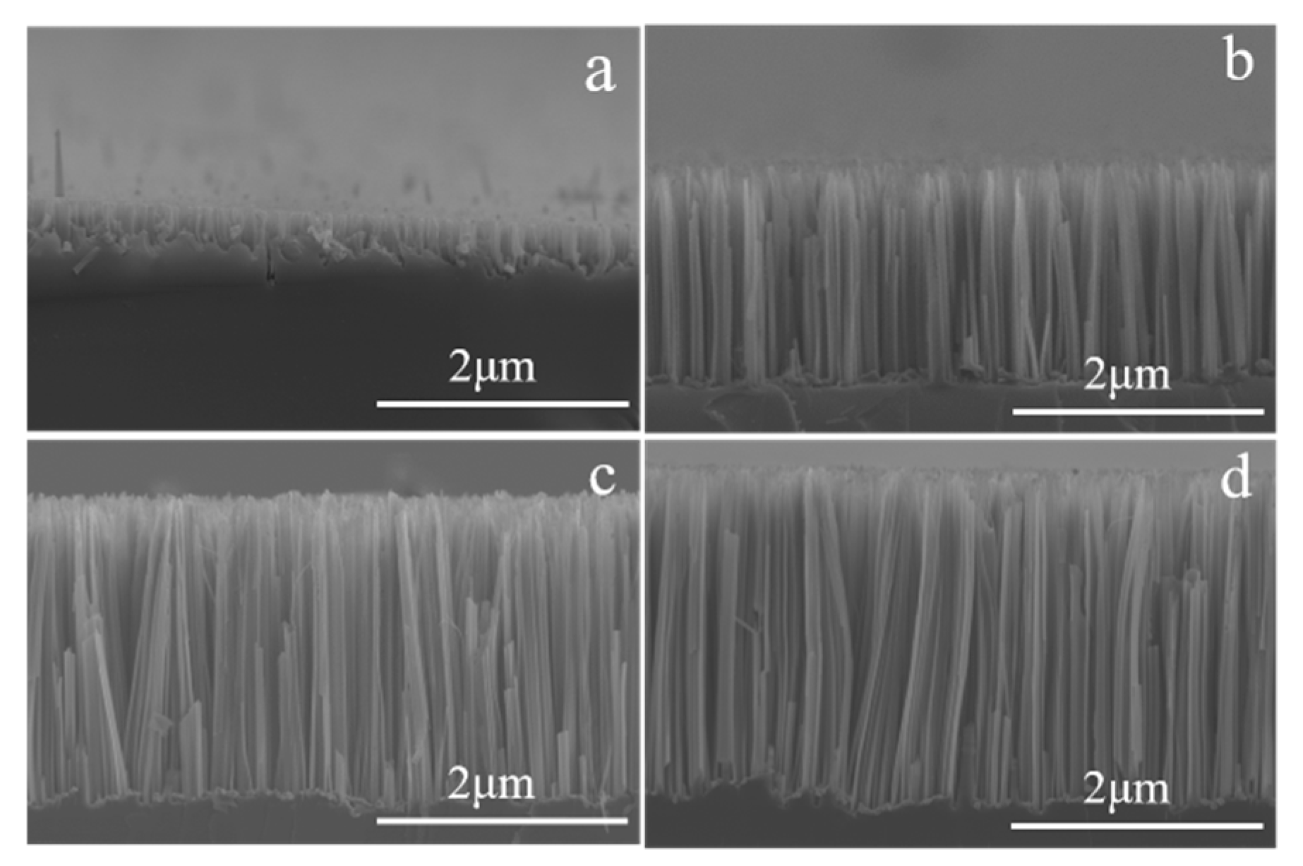
To verify that Fe3+ ions can act as oxidants to etch silicon using electroless deposition technology, a clean N-type silicon wafer (100) with 2–2.7 Ω·cm resistivity was immersed in a plating solution mixed with AuCl4H and HF for 1 min to plate a gold nanoparticle layer on the surface. Then, the gold-coated silicon wafer was placed in the etching solution mentioned above, consisting of 4.6 M HF and FeCl3 etching solution with concentrations of 0 M, 1 M, 1.5 M, and 2 M, respectively, and reacted at 50 °C for 30 min. As shown in Figure 2a–d, the one-dimensional SiNW array structures were successfully prepared, and with the increase of the concentration of FeCl3, SiNW array structures with different lengths were obtained. The above results indicate that Fe3+ is more electronegative than silicon and acts as an oxidant in the HF-FeCl3-H2O system. When clean silicon wafers are immersed in HF-AuCl4H-H2O solution, Au3+ is oxidizing and able to inject holes into the adjacent silicon to gain electrons and reduce to Au, which gradually gathers on the surface of silicon wafers to form uniform nanoparticle layers. The silicon injected with holes is oxidized and is extremely unstable in HF solution, reacting with HF to form soluble H2SiF6 [21,22,23,24] and resulting in the structure of SiNWs (Figure 2a). Then, the gold-plated silicon wafer was immersed in the HF-FeCl3-H2O system. With gold particles as the reactive center, the Fe3+ ions in the solution injected holes into the silicon atoms under the gold nanoparticles, extracted electrons, and were reduced to Fe2+ ions. The silicon under the gold nanoparticles was oxidized and quickly dissolved in HF, leaving small pits. With the continuous progress of the etching, the small pits kept getting deeper, and the gold nanoparticles also moved to the inside of the silicon substrate along with the pits, leaving the uncoated silicon wafer as a silicon wire array structure.
The above results fully verify that Fe3+ can work as the oxidant in the MACE process [9]. To verify the effect of NO3, the silicon wafer with a deposited silver nanoparticle layer was prepared in a solution containing 0.01 M AgNO3 and 4.6 M HF, and the HF-Fe(NO3)3-H2O etching solution system was replaced with HF-HNO3-H2O, keeping the concentration of NO3 consistent. The silicon wafer with silver coating was immersed in two sealed Teflon-lined autoclaves containing HF-Fe(NO3)3-H2O and HF-HNO3-H2O solution, respectively, with a treatment temperature of 50 °C for one hour. The cross-sectional SEM mages of SiNW etching in HF-Fe(NO3)3-H2O and HF-HNO3-H2O solution for 1 h are shown in Figure 3a and Figure 3b, respectively. Figure 3a shows that the silicon wafer was exactly etched in the HF-HNO3-H2O system. The etching rate of Si in the HF-Fe(NO3)3-H2O solution was faster than that in the HF-HNO3-H2O solution, with a consistent molarity of NO3.

3.2. Metal Ions’ Dynamic Effect Analysis

Based on this experimental phenomenon, it was believed that NO3 also had an oxidizing effect in addition to Fe3+. To discuss the influence of metal cations and expand the system range of the etching solution, the fourth-period element corresponding nitrate (M(NO3)x) and HNO3 in the periodic table of elements were researched in this section in the hope that each M(NO3)x would probably represent each main group element’s corresponding M(NO3)x. Considering the metal elements in the fourth period of the periodic table, KNO3, Al(NO3)3, Cr(NO3)3, Mn(NO3)2, Ni(NO3)2, Co(NO3)2, HNO3, and Ca(NO3)2 were finally selected to form the etching solution with HF. After the reaction was completed, the cross-sectional morphology of the silicon wafer was observed with SEM, and the crystal orientation of the silicon nanostructure was observed with TEM.
The cross-sectional view of the SEM in Figure 4 shows that the silver nanoparticle layer is the catalyst, and the etching solution containing M(NO3)x and HF can achieve regular SiNW arrays on the surface of a single-crystal silicon wafer. Most of the arrays are dense, one-dimensional arrays with a line diameter of 100–200 nm. However, the lengths of the SiNW arrays are different in different M(NO3)x etching solutions, which means that the etching rate of silicon is also significantly different in different M(NO3)x etching solutions. After one hour of etching reaction at 50 °C, the length of the SiNW arrays prepared in KNO3 and Al(NO3)3 etching solution was about 3 μm (Figure 4a,b). The length of the SiNW arrays prepared in Mn(NO3)2 and Cr(NO3)3 etching solutions was the shortest, about 1 μm (Figure 4c,d). The lengths of the SiNW arrays prepared in Ni(NO3)2, Co(NO3)3, and Ca(NO3)3 etching solutions were about 5–6 μm (Figure 4e–g). As shown in Figure 4h, observing the microscopic surface morphology of a single silicon wire with a high-power TEM can find that the diameter of a single silicon wire is between 100 and 200 nm, which is also the (100) crystal orientation.
The above results show that in different M(NO3)x systems, the etching rate is also different, although the NO3 is an oxidant that continuously promotes the etching reaction. However, when only the types of metal ions in the M(NO3)x are different, there are still some differences in the SiNW arrays. Therefore, metal ions are still one of the factors that dynamically affect the etching process. Considering the strong complexing ability of F in the etching system, the types of ions are very complex, the toxicity of HF is strong, and the characterization methods of ion species are limited. It was also found that cation concentration has a great influence on the etching results. KNO3 was selected to research the effect of metal ions on the etching reaction, and the influence of different concentrations of KNO3 on the system was also investigated.
Keeping the concentration of HF unchanged, when using 0.48 M KNO3 etching solution, the surface of the silicon wafer was gray-white after reacting at 50 °C for three hours, and, observed under an SEM, as shown in Figure 5a, there was a layer of granular material attached. As shown in the cross-section shown in Figure 5b, the silicon wafer was not etched. The essence of MACE is that the galvanic cell drives the reaction of silicon in an HF solution system with an oxidant. The cathode and anode, the electrolyte, and the connected circuit are indispensable. During the etching reaction, K+ will combine with F to form an insoluble K2SiF6 film that is closely attached to the surface of the silicon wafer, preventing the etching solution from contacting the silicon wafer and thereby inhibiting the occurrence of etching. With 0.05 M KNO3, after the F was completely complexed with the K+, there was still a large amount of residue, which was enough to support the occurrence of subsequent etching reactions. The SiNW arrays are shown in Figure 5c,d. When adding 0.48 M KNO3, most of the F ions in the system were complexed by K+ and formed insoluble K2SiF6, which adhered to the surface of the silicon wafer and inhibited the occurrence of the etching reaction. To verify the crystal composition of the gray-white substance on the surface of the silicon wafer, X-ray diffraction was used to characterize it. As shown in Figure 5f, the positions of the peaks in the XRD pattern correspond exactly to those of standard K2SiF6 (the power diffraction file 52-1831). Therefore, the small particles on the SiNW array side wall shown in Figure 5e are K2SiF6.

3.3. Mechanism Analysis

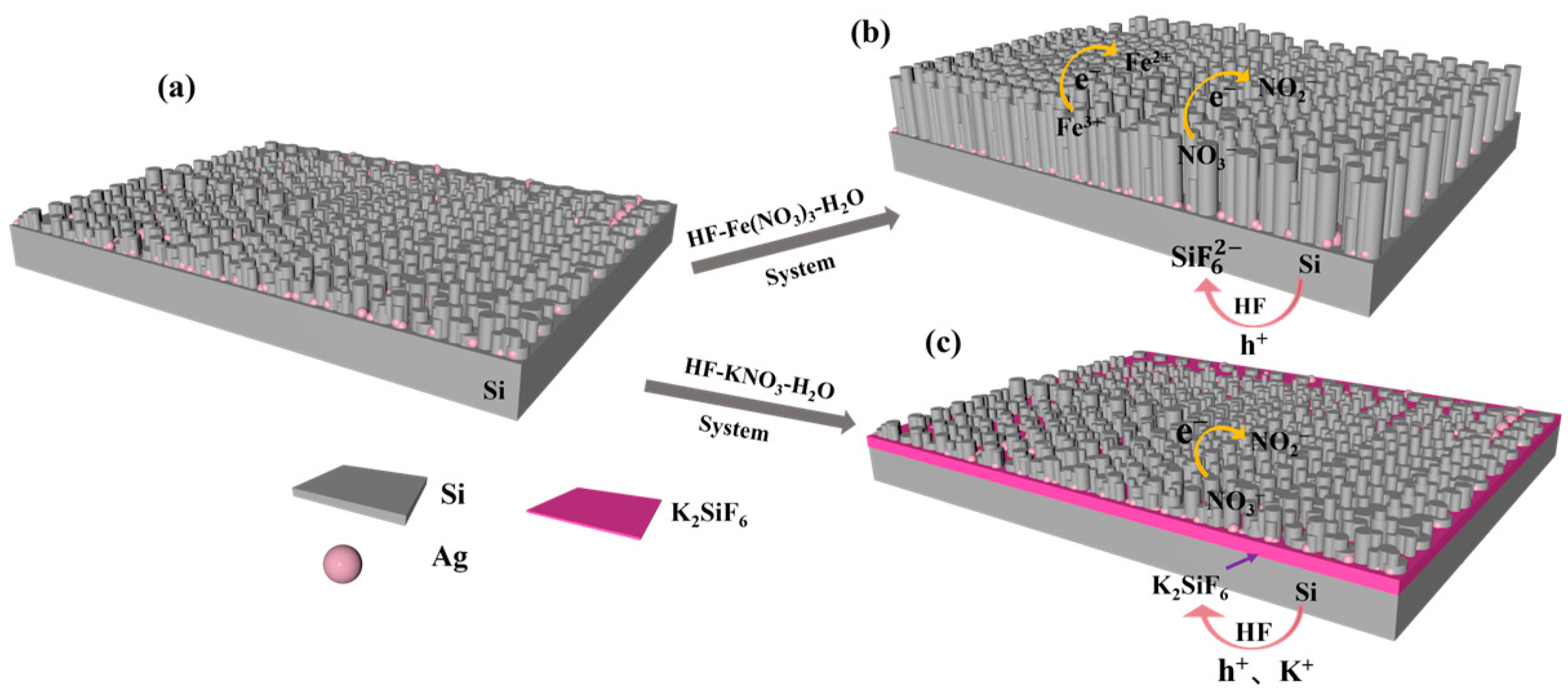
Based on the above experimental results, the influence of Fe3+ and K+ in solution is further understood, and its mechanism is now updated. As shown in Figure 6, during the etching process, NO3 and Fe3+ are both oxidants; as oxidated silicon is dissolved by HF, the silver particles gradually sink as the reaction proceeds, while keeping dissolution and deposition in balance at the same time. In the HF-KNO3-H2O system, as the concentration of KNO3 in the system increases, a layer of K2SiF6 will be formed on the surface of the silicon wafer, which hinders the continuation of the reactions. According to our previous work [10], it is suggested that the anodic dissolution of silicon during MACE of silicon follows both the divalent and tetravalent dissolution processes. The cathode is the reduction of the oxidant. Although Fe3+ and NO3 are cations and anions, respectively, both Fe3+ and NO3 are oxidizing in the etching solution; as they are all reacting at the cathode, they attack the same sections.
In the HF-Fe(NO3)3-H2O system, Fe3+ is reduced to Fe2+, and NO3 is reduced to NO2. In the HF-KNO3-H2O system, most of the F ions in the system are complexed by K+ and form insoluble K2SiF6, which adheres to the surface of the silicon wafer and inhibits the occurrence of etching reactions. The anodic and cathodic half-cell reactions in HF-Fe(NO3)3-H2O and HF-KNO3-H2O system are described as follows [20,33,34]:
In the HF-Fe(NO3)3-H2O system (as shown in Figure 6a)
Anodic:
(1) Si + 2F +2h+  SiF2
SiF2 + 4F +2H+  SiF62− +H2
(2) Si + 2H2O + 4h+  SiO2 + 4H+
SiO2 + 6HF 2H+ + SiF62− + 2H2O
Cathodic:
NO3 + 2H+ +2e  NO2 + H2O
Fe3+ + e  Fe2+
In the HF-KNO3-H2O system (as shown in Figure 6b)
Anodic:
(1) Si + 2F +2h+   SiF2
SiF2 + 4F + 2K+ +2H+  K2SiF6 +H2
(2) Si + 2H2O + 4h+  SiO2 + 4H+
SiO2 + 2K+ + 6HF 2H+ + K2SiF6 + 2H2O
Cathodic:
NO3 + 2H+ +2e  NO2 + H2O

4. Conclusions

In this paper, the oxidative roles of Fe3+ and NO3 during the MACE of silicon were proved, and metal ions’ dynamic effect on MACE of silicon in the HF-M(NO3)x-H2O etching acid solution (where M(NO3)x is: KNO3, Al(NO3)3, Cr(NO3)3, Mn(NO3)2, Ni(NO3)2, Co(NO3)2, HNO3, and Ca(NO3)2) were discussed. The results showed that the type of cation affects the morphology of SiNW arrays and the rate of etching. Crystal composition analysis revealed that the influence of cation type and concentration on MACE is realized by the stability of the metal and its reaction products in the etching solutions. In HF-KNO3-H2O solution, the combination of K+ and F affects the dissolution of SiO2 or directly generates an insoluble substance attached to the wafer surface, thus inhibiting the etching of silicon. As the concentration of KNO3 in the system increases, a layer of K2SiF6 is formed, which hinders the continuation of the etching reactions. This work is further helpful in revealing the metal ions’ dynamic effect on MACE of silicon in the HF-M(NO3)x-H2O etching acid solution, paves the way for further study of the mechanism of MACE, and provides a basis for us to find convenient and low-cost MACE methods.

Author Contributions

Conceptualization, X.Y.; methodology, X.Y. and Y.L.; formal analysis, X.Y. and B.Z.; investigation, X.Y. and Y.L.; resources, L.W. and Y.H.; writing—original draft preparation, B.Z. and Z.L.; writing—review and editing, X.Y., Y.L., T.T., Y.W. and Y.H.; supervision, L.W. and Y.H. All authors have read and agreed to the published version of the manuscript.

Funding

This work was supported by the Key Research and Development Program of Hubei Province (Grant No. 2023BAB122), the National Natural Science Foundation of China (Grant No. 61904130), and the Key Laboratory of Hubei Province for Coal Conversion and New Carbon Materials (Grant No. WKDM201907).

Institutional Review Board Statement

Not applicable.

Informed Consent Statement

Not applicable.

Data Availability Statement

Data is contained within the article.

Acknowledgments

We would like to thank Wang at the Analytical & Test Center of Wuhan University of Science and Technology for their help with SEM analysis.

Conflicts of Interest

The authors declare no conflict of interest.

References

  1. Dhanabalan, A.; Song, B.F.; Biswal, S.L. Extreme Rate Capability Cycling of Porous Silicon Composite Anodes for Lithium-Ion Batteries. ChemElectroChem 2021, 8, 3318–3325. [Google Scholar] [CrossRef]
  2. Nulu, A.; Nulu, V.; Sohn, K.Y. Si/SiOx Nanoparticles Embedded in a Conductive and Durable Carbon Nanoflake Matrix as an Efficient Anode for Lithium-Ion Batteries. ChemElectroChem 2020, 7, 4055–4065. [Google Scholar] [CrossRef]
  3. Ulvestad, A.; Reksten, A.H.; Andersen, H.F.; Carvalho, P.A.; Jensen, I.J.T.; Nagell, M.U.; Mæhlen, J.P.; Kirkengen, M.; Koposov, A.Y. Crystallinity of Silicon Nanoparticles: Direct Influence on the Electrochemical Performance of Lithium Ion Battery Anodes. ChemElectroChem 2020, 7, 4349–4353. [Google Scholar] [CrossRef]
  4. Wang, S.; Liu, H.; Han, J. Comprehensive Study of Au Nano-Mesh as a Catalyst in the Fabrication of Silicon Nanowires Arrays by Metal-Assisted Chemical Etching. Coatings 2019, 9, 149. [Google Scholar] [CrossRef]
  5. Prigoda, K.; Ermina, A.; Bolshakov, V.; Nazarov, D.; Ezhov, I.; Lutakov, O.; Maximov, M.; Tolmachev, V.; Zharova, Y. The Array of Si Nanowires Covered with Ag Nanoparticles by ALD: Fabrication Process and Optical Properties. Coatings 2022, 12, 1748. [Google Scholar] [CrossRef]
  6. Shanshan, W.; Yan, Z. Effect of High-Temperature Annealing on Raman Characteristics of Silicon Nanowire Arrays. Coatings 2023, 13, 793. [Google Scholar] [CrossRef]
  7. Chen, Q.; Zhou, G.; Zhu, J.; Fan, C.; Li, X.G.; Zhang, Y. Ultraviolet Light Emission from Porous Silicon Hydrothermally Prepared. Phys. Lett. A 1996, 224, 133–136. [Google Scholar] [CrossRef]
  8. Chen, Q.; Zhu, J.; Li, X.-G.; Fan, C.G.; Zhang, Y.H. Photoluminescence in Porous Silicon Obtained by Hydrothermal Etching. Phys. Lett. A 1996, 220, 293–296. [Google Scholar] [CrossRef]
  9. Peng, K.Q.; Hu, J.J.; Yan, Y.J.; Wu, Y.; Fang, H.; Xu, Y.; Lee, S.T.; Zhu, J. Fabrication of Single-Crystalline Silicon Nanowires by Scratching a Silicon Surface with Catalytic Metal Particles. Adv. Funct. Mater. 2005, 16, 387–394. [Google Scholar] [CrossRef]
  10. Hu, Y.; Peng, K.-Q.; Qiao, Z.; Huang, X.; Zhang, F.-Q.; Sun, R.-N.; Meng, X.-M.; Lee, S.-T. Metal-Catalyzed Electroless Etching of Silicon in Aerated HF/H2O Vapor for Facile Fabrication of Silicon Nanostructures. Nano Lett. 2014, 14, 4212–4219. [Google Scholar] [CrossRef]
  11. Jiang, W.; Ya, H.; Haichuan, Z.; Haoxin, F.; Yachun, W.; Chenliang, H.; Kui-Qing, P. Oxidant Concentration Modulated Metal/Silicon Interface Electrical Field Mediates Metal-Assisted Chemical Etching of Silicon. Adv. Mater. Interfaces 2018, 5, 1801132. [Google Scholar]
  12. Peng, K.; Lu, A.; Zhang, R.; Lee, S.-T. Motility of Metal Nanoparticles in Silicon and Induced Anisotropic Silicon Etching. Adv. Funct. Mater. 2008, 18, 3026–3035. [Google Scholar] [CrossRef]
  13. Hu, Y.; Jin, C.; Liu, Y.; Yang, X.; Liao, Z.; Zhang, B.; Zhou, Y.; Chen, A.; Wu, L.; Liu, J.; et al. Metal Particle Evolution Behavior during Metal Assisted Chemical Etching of Silicon. ECS J. Solid State Sci. Technol. 2021, 10, 084002. [Google Scholar] [CrossRef]
  14. Peng, K.Q.; Yan, Y.J.; Gao, S.P.; Zhu, J. Synthesis of Large-Area Silicon Nanowire Arrays via Self-Assembling Nanoelectrochemistry. Adv. Mater. 2002, 14, 1164–1167. [Google Scholar] [CrossRef]
  15. To, W.-K.; Tsang, C.-H.; Li, H.-H.; Huang, Z. Fabrication of N-Type Mesoporous Silicon Nanowires by One-Step Etching. Nano Lett. 2011, 11, 5252–5258. [Google Scholar] [CrossRef]
  16. Leng, X.; Wang, C.; Yuan, Z. Progress in Metal-Assisted Chemical Etching of Silicon Nanostructures. Procedia CIRP 2020, 89, 26–32. [Google Scholar] [CrossRef]
  17. Venkatesan, R.; Arivalagan, M.K.; Venkatachalapathy, V.; Pearce, J.M.; Mayandi, J. Effects of Silver Catalyst Concentration in Metal Assisted Chemical Etching of Silicon. Mater. Lett. 2018, 221, 206–210. [Google Scholar] [CrossRef]
  18. Aca-López, V.; Quiroga-González, E.; Gómez-Barojas, E.; Światowska, J.; Luna-López, J.A. Effects of the Doping Level in the Production of Silicon Nanowalls by Metal Assisted Chemical Etching. Mater. Sci. Semicond. Process. 2020, 118, 105206. [Google Scholar] [CrossRef]
  19. Han, H.; Huang, Z.; Lee, W. Metal-Assisted Chemical Etching of Silicon and Nanotechnology Applications. Nano Today 2014, 9, 271–304. [Google Scholar] [CrossRef]
  20. Hu, Y.; Fu, H.; Wang, J.; Sun, R.; Wu, L.; Liu, Y.; Xu, J.; Liu, J.; Peng, K.-Q. Carbon Induced Galvanic Etching of Silicon in Aerated HF/H2O Vapor. Corros. Sci. 2019, 157, 268–273. [Google Scholar] [CrossRef]
  21. Hassan, H.H.; Chazalviel, J.N.; Neumann-Spallart, M.; Ozanam, F.; Etman, M. Chemical Limitations to the Anodic Dissolution of P-Si in Fluoride Media in the Presence of Alkali Metal Cations. J. Electroanal. Chem. 1995, 381, 211–214. [Google Scholar] [CrossRef]
  22. Hassan, H.H.; Fotouhi, B.; Sculfort, J.L.; Abdel-Rehiem, S.S.; Etman, M.; Ozanam, F.; Chazalviel, J.N. Effect of Alkali-Metal and Some Quaternary-Ammonium Cations on the Anodic Dissolution of p-Si in Fluoride Media. J. Electroanal. Chem. 1996, 407, 105–113. [Google Scholar] [CrossRef]
  23. Nahm, K.S.; Seo, Y.H.; Lee, H.J. Formation Mechanism of Stains during Si Etching Reaction in HF–Oxidizing Agent–H2O Solutions. J. Appl. Phys. 1997, 81, 2418–2424. [Google Scholar] [CrossRef]
  24. Hun, S.Y.; Suk, N.K.; Bang, L.K. Mechanistic Study of Silicon Etching in HF-KBrO3-H2O Solution. J. Electrochem. Soc. 1993, 140, 1453. [Google Scholar]
  25. Lin, H.; Wu, F.; Gao, P.; Shen, W. Shape-Controlled Silicon Microwire Arrays from Au–Ag-Catalyzed Metal-Assisted Chemical Etching for Radial Junction Solar Cells. ACS Appl. Energy Mater. 2019, 2, 5871–5876. [Google Scholar] [CrossRef]
  26. Booker, K.; Rahman, S.; Chong, T.-K.; Mankelow, R.; Weber, K.; Blakers, A. A Robust Metal-Assisted Etching Process for Ag-Catalyzed Texturing of Silicon. IEEE J. Photovolt. 2015, 5, 766–773. [Google Scholar] [CrossRef]
  27. Shaoyuan, L.; Wenhui, M.; Yang, Z.; Xiuhua, C.; Yongyin, X.; Mingyu, M.; Wenjie, Z.; Feng, W. Fabrication of Porous Silicon Nanowires by MACE Method in HF/H2O2/AgNO3 System at Room Temperature. Nanoscale Res. Lett. 2014, 9, 196. [Google Scholar] [CrossRef]
  28. Milazzo, R.G.; D’arrigo, G.; Spinella, C.; Grimaldi, M.G.; Rimini, E. Ag-Assisted Chemical Etching of (100) and (111) n-Type Silicon Substrates by Varying the Amount of Deposited Metal. J. Electrochem. Soc. 2012, 159, D521. [Google Scholar] [CrossRef]
  29. Tian, B.; Zhang, J. Morphology-Controlled Synthesis and Applications of Silver Halide Photocatalytic Materials. Catal. Surv. Asia 2012, 16, 210–230. [Google Scholar] [CrossRef]
  30. Bi, Y.; Ye, J. In Situ Oxidation Synthesis of Ag/AgCl Core–Shell Nanowires and Their Photocatalytic Properties. Chem. Commun. 2009, 2009, 6551–6553. [Google Scholar] [CrossRef]
  31. Bi, Y.; Ye, J. Direct Conversion of Commercial Silver Foils into High Aspect Ratio AgBr Nanowires with Enhanced Photocatalytic Properties. Chem.—A Eur. J. 2010, 16, 10327–10331. [Google Scholar] [CrossRef] [PubMed]
  32. Bi, Y.; Ye, J. Heteroepitaxial Growth of Platinum Nanocrystals on AgCl Nanotubes via Galvanic Replacement Reaction. Chem. Commun. 2010, 46, 1532. [Google Scholar] [CrossRef] [PubMed]
  33. De Groot, M.; Koper, M.T. The Influence of Nitrate Concentration and Acidity on the Electrocatalytic Reduction of Nitrate on Platinum. J. Electroanal. Chem. 2004, 562, 81–94. [Google Scholar] [CrossRef]
  34. Dima, G.E.; Beltramo, G.L.; Koper, M.T.M. Nitrate Reduction on Single-Crystal Platinum Electrodes. Electrochim. Acta 2005, 50, 4318–4326. [Google Scholar] [CrossRef]
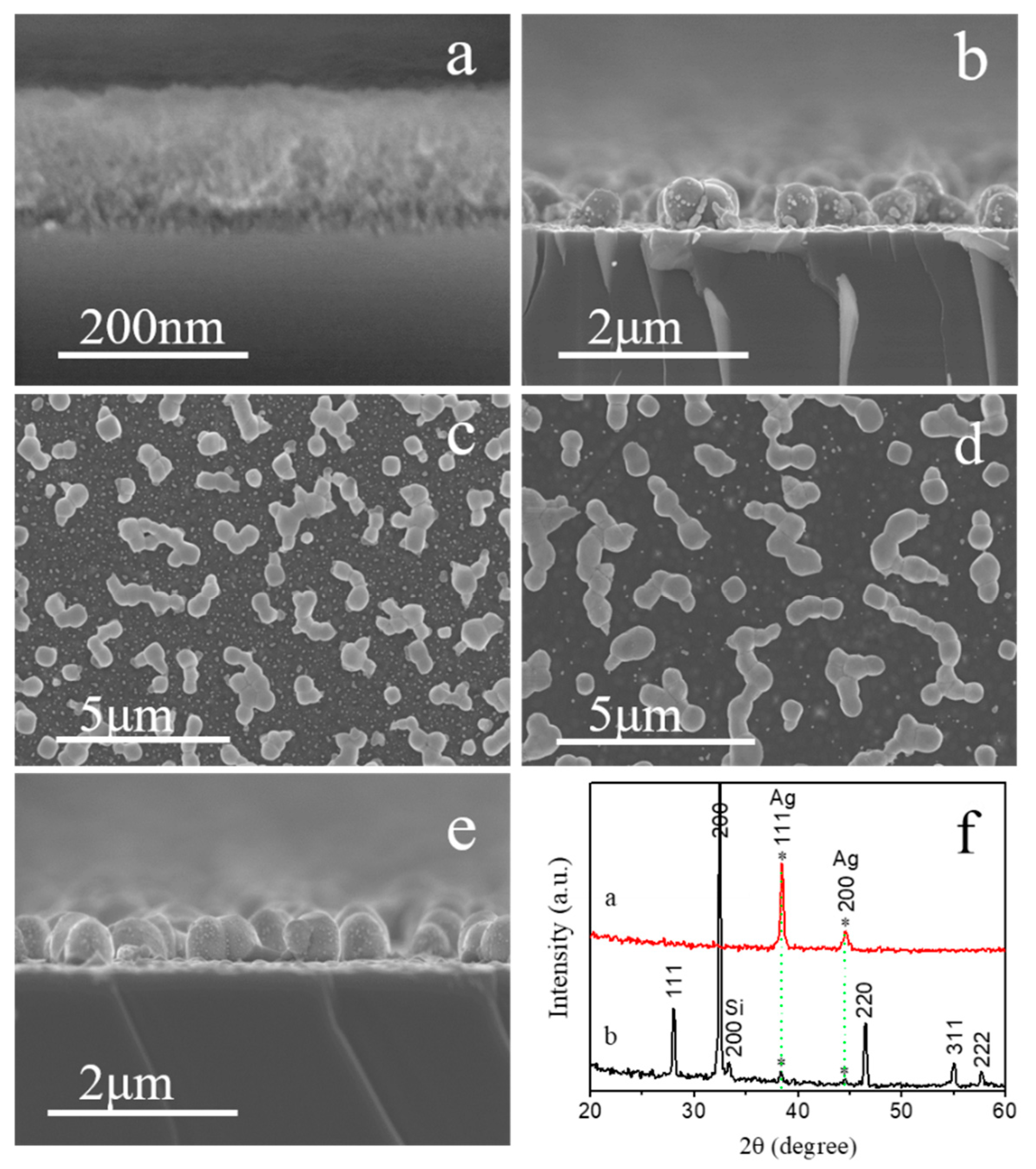
Figure 1. SEM morphology of silicon wafer etched in etching solution of 1.5 M FeCl3 and 4.6 M HF at 50 °C for 30 min: (a) silicon etched without silver plating, (b) silicon etched with silver plating, (c) top view of Figure 1b, (d) sample etched with silver plating and immersed in concentrated HNO3 for 30 min, (e) cross-sectional of Figure 1d, (f) The XRD curve of the silver-coated silicon surface (red) and silver-coated silicon wafer after reaction in FeCl3-HF solution (black), * represents silver particles.
Coatings 14 01405 g001
Figure 2. The cross-sectional view of gold-plated silicon wafer etched in 4.6 M HF and different concentrations of FeCl3 etching solution at 50 °C for 30 min: (a) 4.6 M HF and 0 M FeCl3, (b) 4.6 M HF and 1 M FeCl3, (c) 4.6 M HF and 1.5 M FeCl3, and (d) 4.6 M HF and 2 M FeCl3.
Coatings 14 01405 g002
Figure 3. The SEM cross-section morphology of silver-plated SiNWs prepared in the etching system of 4.60 M HF and M(NO3)x: (a) 0.48 M HNO3, (b) 0.16 M Fe(NO3)3.
Coatings 14 01405 g003
Figure 4. The surface micro and nano structure morphology of the silicon wafer etched in the M(NO3)x and 4.6 M HF etching solution for one hour: (a) 0.05 M KNO3, (b) 0.16 M Al(NO3)3, (c) 0.24 M Mn(NO3)2, (d) 0.16 M Cr(NO3)3, (e) 0.24 M Ni(NO3)2, (f) 0.24 M Co(NO3)2, (g) 0.24 M Ca(NO3)2, (h) TEM of one piece of silicon nanowire etched in etching solution of 0.05 M KNO3.
Coatings 14 01405 g004
Figure 5. The morphology and structure analyses of silicon wafer coated with a silver nanoparticle layer and reacted in different concentrations of KNO3 and 4.6 M HF etching solutions: (a) 0.40 M KNO3, etching for 3 h, (b) cross-sectional view of Figure 5a, (c) 0.05 M KNO3, etching for 30 min, (d) cross-section of Figure 5c, (e) TEM of one silicon nanowire etched in 0.05 M KNO3 for 30 min, (f) XRD of sample etched in 0.05 M KNO3 for 30 min.
Coatings 14 01405 g005
Figure 6. Schematic diagrams illustrating. (a) Silicon wafers coated with silver nanoparticle layer. (b) Silicon wafer coated with silver nanoparticle layer and reacted in HF-Fe(NO3)3-H2O system. (c) Silicon wafer coated with silver nanoparticle layer and reacted in HF-KNO3-H2O system.
Coatings 14 01405 g006
Disclaimer/Publisher’s Note: The statements, opinions and data contained in all publications are solely those of the individual author(s) and contributor(s) and not of MDPI and/or the editor(s). MDPI and/or the editor(s) disclaim responsibility for any injury to people or property resulting from any ideas, methods, instructions or products referred to in the content.