Article

Wear and Corrosion Resistance of ZrN Coatings Deposited on Ti6Al4V Alloy for Biomedical Applications

1
Institute of Electronics, Bulgarian Academy of Sciences, 72 Tzarigradsko Chaussee Blvd, 1784 Sofia, Bulgaria
2
Central Laboratory of Solar Energy and New Energy Sources, Bulgarian Academy of Sciences, 72 Tzarigradsko Chaussee Blvd, 1784 Sofia, Bulgaria
3
Institute of Optical Materials and Technologies, Bulgarian Academy of Sciences, 109 Acad. G. Bonchev Str., 1113 Sofia, Bulgaria
4
Department of Machine Building and Transport, Faculty of Physics and Technology, Plovdiv University Paisii Hilendarski, 24 Tzar Asen Str., 4000 Plovdiv, Bulgaria
5
Department of Physical Chemistry, Plovdiv University Paisii Hilendarski, 24 Tzar Asen Str., 4000 Plovdiv, Bulgaria
6
Department of Mathematics, Informatics and Natural Sciences, Technical University of Gabrovo, 4 H. Dimitar Str., 5300 Gabrovo, Bulgaria
*
Author to whom correspondence should be addressed.
Coatings 2024, 14(11), 1434; https://doi.org/10.3390/coatings14111434
Submission received: 23 October 2024 / Revised: 2 November 2024 / Accepted: 6 November 2024 / Published: 11 November 2024
(This article belongs to the Special Issue Anti-corrosion Coatings of Metals and Alloys—New Perspectives)

Abstract

:
Zirconium nitrides films were synthesized on Ti6Al4V substrates at a bias voltage of −50 V, −80 V, −110 V and −150 V by the direct current (DC) reactive magnetron sputtering technique. The as-deposited coatings were characterized by X-ray diffraction (XRD), Fourier-transform infrared (FTIR) spectroscopy, scanning electron microscopy (SEM) and atomic force microscopy (AFM). The wear and corrosion resistance of the obtained ZrN coatings were evaluated to determine the possibility for their implementation in modern biomedical applications. It was found that the intensity of the diffraction peak of the Zr-N phase corresponding to the (1 1 1) crystallographic plane rose as the bias voltage increased, while the ZrN coatings’ thickness reduced from 1.21 µm to 250 nm. The ZrN films’ surface roughness rose up to 75 nm at −150 V. Wear tests showed an increase in the wear rate and wear intensity as the bias voltage increased. Corrosion studies of the ZrN coatings were carried out by three electrochemical methods: open circuit potential (OCP), cyclic voltammetry (polarization measurements) and electrochemical impedance spectroscopy (EIS). All electrochemical measurements confirmed that the highest protection to corrosion is the ZrN coating, which was deposited on the Ti6Al4V substrate at a bias voltage of −150 V.

1. Introduction

Nowadays, metallic implant materials such as stainless steel, titanium and its alloys have been applied for the needs of modern biomedicine. The main medical approach for the past few decades is the use of metal nails, screws, and splints as implants for failed tissues replacement and the stabilization of osseous structures, which are not inert enough in the human body and cause side effects [1]. Ti-based alloys are the most commonly used for orthopedic implants due to their attractive functional properties, such as biocompatibility, inertness, high strength and good corrosion resistance, making these materials promising for the applications in the field of the contemporary medicine [2,3,4,5]. Ti–6Al–4V alloy can be considered as the most suitable for the replacement and restoration of damaged structures due to their good resistance to corrosion, biological properties, high specific resistance and good chemical stability. Despite these desirable properties, this material shows a high modulus of elasticity (110 GPa) that seriously limits its utilization as an implant for artificial joints. For comparison, the elastic modulus of human bone is between 10 and 40 GPa [6]. On the other hand, metals allergy is also a serious problem. This allergy caused by the release of ions can lead to irritation of the tissues around the implant [7,8]. Other main disadvantages of Ti-6Al-4V alloy are a high friction coefficient, low wear resistance and a low hardness [9]. These issues can be overcome by applying appropriate techniques for surface treatment. The coatings deposition is a possible way to enhance the properties of the materials.
Recently, ZrN films have attracted the attention of scientists due to their excellent mechanical properties, stability in thermal environments, good corrosion resistance, and good biological properties. These exceptional properties of ZrN coatings make them applicable in different fields of science, including bioengineering and industrial applications. ZrN layers can be obtained by different techniques; the most commonly used are physical vapor deposition (PVD) and chemical vapor deposition (CVD) [10,11]. Researchers in [12] fabricated ZrN films on CoCrMo bases by arc-PVD to enhance fretting corrosion resistance. Zirconium nitride coatings were found to have little release of cobalt ions during corrosion tests. The authors in [10] investigated the corrosion resistance of the ZrN coatings deposited on 304 L stainless steels substrates at different scan rates between 10 and 600 mV/min by electrochemical measurement. It was found that a higher polarization scan rate corresponds to the rose current of the corrosion density Icorr and passive current density Ip for 304 L stainless steel bases. In [13], the investigators obtained ZrN films on three types of substrates: C (carbon), Si (1 0 0) wafer and titanium by direct current reactive magnetron sputtering where the deposition time, Ar/N2, ratio, and base temperature were varied. As a result, the thicker film at lower N2 partial pressure was obtained. As regards the substrate temperature, ZrN coatings exhibited high resistance to corrosion as opposed to the pure Ti substrate at low temperature. In reference [14], the effect of the pressure on the structure and mechanical performance of Zr-based films, deposited on Zr alloy bases by radio-frequency magnetron sputtering, was considered. The best correlation between the mechanical properties and pressure was achieved for ZrN films at a pressure of 0.7 Pa compared to ones at 0.3 Pa, 0.5 Pa and 0.9 Pa. Other investigators acquired ZrN coatings on hardened steel substrates by reactive magnetron sputtering at the constant power of 700 W and a substrate bias voltage of about −10 V, varying the nitrogen flow rate from 3 to 6 sccm. The film fabricated at 3 sccm N2 demonstrated the highest roughness, and the lowest one was estimated to be for a coating produced at 6 sccm N2 [15]. The researchers in [16] grew ZrN films by the ion beam sputtering technique on 304 stainless steel substrates with varying N2/Ar ratios and substrate temperatures. They found that the change in the concentration of flow nitrogen influenced the preferential crystalline orientation. At lower flow nitrogen, the (111) crystallographic plane is preferred. Increasing the nitrogen concentration, the ZrN crystalline phase disappeared due to transformation into an amorphous condition. In reference [17], the mechanical and tribological properties as well as the electrochemical behavior of ZrN films on 304 stainless steel specimens were improved. The crystalline structure and composition were estimated and exhibited good correlation with high resistance to plastic deformation, wear and corrosion, making these materials potential candidates for biomedical applications. In reference [18], the authors obtained ZrN coatings at low temperature on 2024 Al alloy substrates by the vacuum arc deposition method. As a result, the films were homogeneous and dense with a crystal structure, high hardness, good wear and corrosion resistance. The investigators in reference [19] analyzed ZrN films’ corrosion and tribological properties on CoCrMo alloy substrates by radio-frequency magnetron sputtering. The produced films had a hardness of 21 GPa. The researchers in [20] deposited ZrN coatings on AZ91 magnesium alloy substrates using a filtered cathodic arc deposition system to characterize the corrosion behavior of the obtained films. The ZrN films showed enhanced corrosion resistance. Silicon specimens were used as substrates for the formation of ZrN coatings by plasma electrolytic oxidation. They had high crystallinity, porous morphology and a high growth rate [21]. The authors in [22,23] obtained ZrN films on Si, M2 high-speed steel, 304L stainless steel, and 316 stainless steel substrates at a bias voltage of 0 V, −25 V, −50 V, −65 V, −75 V, −95 V and −100 V by arc ion plating, radio-frequency magnetron sputtering and high-power impulse magnetron sputtering techniques. The purpose is to investigate the influence of the bias voltage on the microstructure, morphology, mechanical properties and electrochemical behavior of the as-deposited ZrN coatings. It was found out that the crystallites size of ZrN films decreases from 30 to 15 nm and the roughness increases at a bias voltage of −100 V. The nanohardness and the resistance to the corrosion of ZrN samples were improved by applying a higher bias voltage. The biocompatibility and antibacterial properties of different specimens (uncoated Ti6Al4V, anodized, and coated with titanium nitride or zirconium nitride) were investigated. For all of the tested bacterial strains, biofilms grown on the zirconium nitride surface showed a higher percentage of dead bacteria compared to other substrates [24]. The antimicrobial activity of Ti-ZrN/Ag coatings for application as biomaterials was determined [25]. The investigators in [26] exhibited the effect of the wear-resistant coatings application on the force parameters of the cutting process and the tool life during the end milling of titanium alloys. The experiments were carried out on VT20 titanium alloy with uncoated end milling cutters and cutters with the Ti-TiN-(Ti,Cr,Al)N and Zr-ZrN-(Zr,Cr,Al)N films. It was found out that tools with the coatings have a 2.5–3-fold higher tool life compared to the tool life of an uncoated tool. The authors in [27] analyzed the application of ZrN layers for the mitigation of the development of fretting wear processes at the surfaces of push fit joint elements. The results demonstrated a significant mitigation of fretting wear on samples with ZrN coatings. The mechanical properties and impact resistance of multilayered TiAlN/ZrN coatings were evaluated by the researchers in reference [28]. The results showed a higher hardness (33–38 GPa) of the multilayered TiAlN/ZrN coatings compared to the hardness of the single ZrN (30 GPa) and TiAlN(31 GPa) layers.
It is obvious that ZrN coatings are commonly deposited on different substrates by various techniques and have a large number of biomedical applications. From another point of view, the Ti6Al4V alloy is very promising for the implementation in the field of implant manufacturing. However, the data for the ZrN films deposition on Ti6Al4V substrates at different technological conditions are very limited. In the present study, we have created an appropriate technology for zirconium-based films production on implant material for biomedical applications. For this purpose, we deposited ZrN coatings on Ti6Al4V substrates at a bias voltage of −50 V, −80 V, −110 V and −150 V by the DC magnetron sputtering method. This paper aims to investigate the effect of bias voltages on the structure, morphology, wear resistance and corrosion behavior of the ZrN coatings applied on Ti6Al4V substrates. The expected results could contribute to new knowledge on the influence of the technological conditions during the ZrN thin films deposition on the Ti6Al4V substrate on the functional properties in terms of the surface roughness and corrosion properties. The results obtained in this study are discussed concerning the potential applications in the field of modern biomedicine.

2. Materials and Methods

2.1. ZrN Films Deposition

Zirconium nitride coatings were grown at bias voltages of −50 V, −80 V, −110 V and −150 V on Ti6Al4V substrates applying direct current (DC) magnetron sputtering. The diameter of the sputtered target was 100 mm with a high purity of Zr of about 99.8%. The influence of the negative bias voltage on the structure, surface roughness, and corrosion properties was investigated. The studied bias voltages were −50, −80, −110, and −150 V.
Prior to being introduced into the vacuum chamber, the specimens were pre-polished mechanically. The ZrN coatings deposition on Ti6Al4V bases was performed according to the following technological regime:
  • Cathode cleaning—This process includes sputter cleaning of the Ti6Al4V substrates by Ar+ plasma to eliminate oxide layers from their surface and ensure a purity of the process. Also, it is necessary to decrease the surface roughness, which has a negative effect on the obtained coating’s properties. This process of high energetic ion bombardment is carried out at the following conditions:
    • A working pressure (the working gas is Ar)—before the deposition process, the vacuum chamber was evacuated to a base pressure of PAr = 8 Pa;
    • A discharge voltage U = 950 V;
    • A discharge current I = 0.1 A;
    • A temperature t° = 230 °C;
    • A cleaning time t = 10 min.
  • Deposition of intermediate pure Zr layer in order to enhance the adhesion between the coatings and the substrate—This process is evaluated at the following conditions:
    • A working pressure (the working gas is Ar) PAr = 9 × 10⁻² Pa;
    • A discharge voltage U = 460 V;
    • A discharge current I = 1 A;
    • A temperature t° = 250 °C;
    • Deposition time t = 3 min.
  • Deposition process of ZrN coatings—During the process, Ti6Al4V substrates were heated up to a temperature of 250 °C. The process took place in Ar-N2 atmosphere. The inert Ar and reactive N2 gases mixture was introduced into the chamber by means of valves. The inert Ar and reactive N2 gas flows were regulated by vacuum meter indicators to determine the working pressure values. The experiments for the production of ZrN films were performed according to the following parameters:
    • A nitrogen pressure PN2 = 5.6 × 10⁻³ Pa;
    • A working pressure PAr/N2 = 1.1 × 10⁻¹ Pa;
    • A voltage U = 480 V;
    • A bias voltage—zirconium nitride coatings were deposited at bias voltages of −50 V, −80 V, −110 V and −150 V;
    • A constant current I = 1 A;
    • A deposition time t= 60 min.
The principle scheme of the direct current magnetron sputtering technique is shown in Figure 1.

2.2. Structural Characterization

The X-ray diffraction (XRD) method is used to determine the crystalline structure of the coatings. The measurements were performed at 2θ scale from 10 to 90° with a step size of 0.1° and counting time of 1.5 s. The International Center for Diffraction Data (ICDD) database was used to identify the phases of the coatings.
Infrared Fourier-transform (FTIR) spectroscopy was registered with a Shimadzu Spectrophotometer IRPrestige-21 (with resolution of 4 621 cm−1, Shimadzu Corporation, Kyoto, Japan) in the spectral range from 350 to 4000 cm−1. The spectra are taken in reflectance mode by using specular reflectance attachment SRM-8000. An Al mirror has been used as the background. The Kramer–Koenig transformation was applied to evaluate the absorption spectrum from the measured reflection spectrum.
The thickness and cross-section morphology of ZrN coatings were characterized by means of scanning electron Microscopy (SEM). The experiments were carried out at an accelerated voltage of 20,000 V. The SEM images were obtained by a microscope “LYRA I XMU”, Tescan Orsay Holding (Brno, Czech Republic), using secondary electrons. The chemical composition of the ZrN coatings on Ti6Al4V was evaluated by EDX analysis.

2.3. AFM Investigations

The surface topology, as well the roughness of the ZrN layers and the bare substrate, were determined by means of atomic force microscopy (AFM)—MFP-3D, Asylum Research, Oxford Instruments, Santa Barbara, CA, 93117, USA. The scanning measurements were carried out in non-contact mode (AC-mode) of operation, and the scanned area for all samples was 20 × 20 µm. A standard type of Si-Tap300Al-G (budget Sensors) with a frequency of 300 kHz and an elasticity coefficient of k = 40 N/m was applied. The surface roughness (root mean square deviation, RMS) was determined with the assistance of special software—IgorPro 6.37.

2.4. Wear Resistance Investigations

The wear resistance of ZrN coatings was investigated by the ball on flat sliding wear test by the test stand CИИП-1 with horizontal orientation of the test surface. For this purpose, a mineral–ceramic sphere of Al2O3 was used for the counter body with a diameter of 3 mm. The experiments were carried out at a force of 0.5 N and constant velocity of 10 mm/s with friction on the linear reciprocation drive sample (Reciprocation drive) without the presence of lubricant and air in room temperature.

2.5. Corrosion Resistance Investigations

The samples under study were 3 mm thick lamellae shaped as isosceles triangles with one side coated with ZrN, and the rest of them were bare substrate. Before measurements, each sample was connected to a crocodile clip; then, the place of contact and the non-coated sides of each sample were insulated with a non-conductive polish and allowed to dry overnight under a fume cupboard. All electrochemical measurements were carried out in a standard, non-compartmentalized electrochemical cell made of Pyrex glass with a working volume of 10–50 mL in a three-electrode configuration. The samples were connected as working electrodes, whilst a Ag/AgCl, 3 M KCl and a Pt wire were used as reference and auxiliary electrodes, respectively, connected to an electrochemical workstation Autolab 302 N (Metrohm, Utrecht, The Netherlands). The equipment consists of a potentiostat–galvanostat (main body) and 4 additional modules, such as a frequency response analyzer (FRA-module) for performing electrochemical impedance spectroscopy, EIS; frequency boosting module; UV-Vis spectro-electrochemical module; and a module for kinetic studies (rotating disc electrode), which were all controlled by Nova 2.1.6 software. Buffer solutions and the electrolytes for running electrochemical impedance spectroscopy (EIS) were prepared with ultrapure water (Adrona B30 Bio, Vilnius, Lithuania) and reagent grade chemicals. The corrosion resistance of the samples has been probed as previously described [29]. The ability of the ZrN coatings to protect the substrate surface from oxidative dissolution was estimated on the basis of impedance spectra (EIS), which were acquired over the frequency range from 100 kHz to 1 Hz with 10 frequencies per decade. Then, the equilibrium potential was measured in the same solution at zero current flowing through the electrochemical cell. Measurements were performed in a 0.1 M KCl neutral aqueous solution containing 5 mM ferri/ferro hexacyanoferrates playing the role of a redox probe. The dependencies of current on the applied potential (also termed as polarization characteristics of the samples) were determined by means of cyclic voltammetry at a 20 mV/s scan rate under conditions, mimicking the physiological ones: in 0.1 M phosphate buffer with pH = 7.4, both without and with NaCl added to a final concentration of 0.1 M, and were recorded over the potential region from −0.8 to 0.8 V vs. Ag/AgCl, 3 M KCl reference system. All potentials, if not otherwise stated, were reported versus this reference electrode.

3. Results and Discussion

3.1. X-Ray Diffraction (XRD) Method

XRD patterns of the ZrN magnetron-sputtered coatings, produced at different substrates bias voltages, are displayed in Figure 2. The main crystal phase in the ZrN films is a face-centered cubic crystal structure, type NaCl (Fm3m). Diffraction lines from the Zr sublayer do not appear. The phases in ZrN were identified according to the International Center for Diffraction Data (ICDD) Database PDF #350753. At all substrates bias voltages, an existence of diffraction maxima of (1 1 1), (2 0 0), (2 2 0) planes is clearly observed. The intensity of the diffraction peak in direction (1 1 1) rises as the bias voltage increases up to −150 V. Apparently, the grains belonging to the (1 1 1) plane are dominating as the intense Bragg peak at 2θ = 33.4° becomes more remarkable as the bias voltage increases. This is a result of the higher kinetic energy of Zr atoms compared to the nitrogen ones which come directly from the target to the substrate. Applying the negative higher bias voltage to the substrate leads to the faster film growth rate and formation of the ZrN phase. For the (2 0 0) plane at all bias voltages, no significant changes were observed. The same tendency was considered for the other diffraction peaks. Therefore, the transformation in the preferred orientation of the coating toward the (111) plane occurs at a higher bias. According to the literature, the main peaks in the ZrN cubic phase are (1 1 1) and (2 0 0) [30,31]. The technological conditions during the deposition process such as the bias voltage, nitrogen pressure, and substrate temperature contribute to the preferred orientation of the crystallites in the ZrN coatings [32,33]. The bias voltage is responsible for ion bombardment energy on the growth degree of the film as it impacts on the structure and characteristics of the produced layers [34,35]. The decrease in the bias voltage correlates with higher residual compressive stress because the defect density increases [36]. On the other hand, raising in the bias voltage leads to a higher number of ionized Ar+ ions and produces changes in the quality of the film, such as the density, adhesion, and surface roughness [37]. Also, enhancing the bias voltage raises the atomic mobility and atomic rearrangement. The diffraction patterns did not exhibit an attendance of amorphous halos, proving the high degree of crystallinity of the deposited ZrN coatings. The diffraction peaks of α-Ti and β- Ti, coming from the substrate, were also exhibited, proving the two-phase structure of the bare substrate Ti6Al4V.

3.2. Fourier-Transform Infrared (FTIR) Spectroscopy

FTIR spectroscopy is a fast and reliable technique for the identification of the functional groups and different vibrational modes presented in the film structure. The TIR reflectance spectra of the bare substrate Ti6Al4V and ZrN coatings, obtained at different bias voltages, are given in Figure 3.
ZrN films are reflective, and their reflectance in the infrared spectral range is much greater than the reflectance of the bare substrate. The FTIR absorption spectrum of the ZrN films as a function of bias voltages is shown in Figure 4. Two clear peaks were observed at the wavelengths of 366 cm−1 and 412 cm−1, corresponding to the oscillations in the substrate. For all samples, there is a characteristics band at 694 cm−1, which is assigned to the out-of-plane vibrations stretching from the simple Zr-N bonds [38,39]. The FTIR absorption spectra are presented in the spectral region of interest from 350 to 600 cm−1.
The characteristic peak for all ZrN films is seen at 422 cm−1 assigned to the Zr-N bonds as the strongest band is manifested for the film deposited at a bias voltage of −80 V. Additionally, two weak bands appeared at 480 cm−1 and 525 cm−1. They are attributed to the Zr-N absorption [40]. Increasing the bias voltage up to −150 V, these two lines disappeared. Based on the performed analysis, it can be summarized that the presence of Zr-N bonds confirmed the formation of the ZrN phase.

3.3. Scanning Electron Microscopy (SEM)

Figure 5 exhibits cross-sectional morphologies of the ZrN coatings deposited at a bias voltage of −50 V and −110 V. Both coatings show a dense structure. It can be seen that the thickness of the as-deposited coatings decreases to 250 nm as the bias voltage increases. Due to the higher energy of the falling on the substrate Zr ions, their quantity reduces and the thickness decreases, too. The chemical composition of the ZrN coating on the Ti6Al4V substrate was determined by EDX analysis. The results showed 49.81 wt.% Zr, 34.49 wt.% N, 14.27 wt.% Ti, 0.16 wt. % Al and 1.26 wt% V.

3.4. Atomic Force Microscopy (AFM)

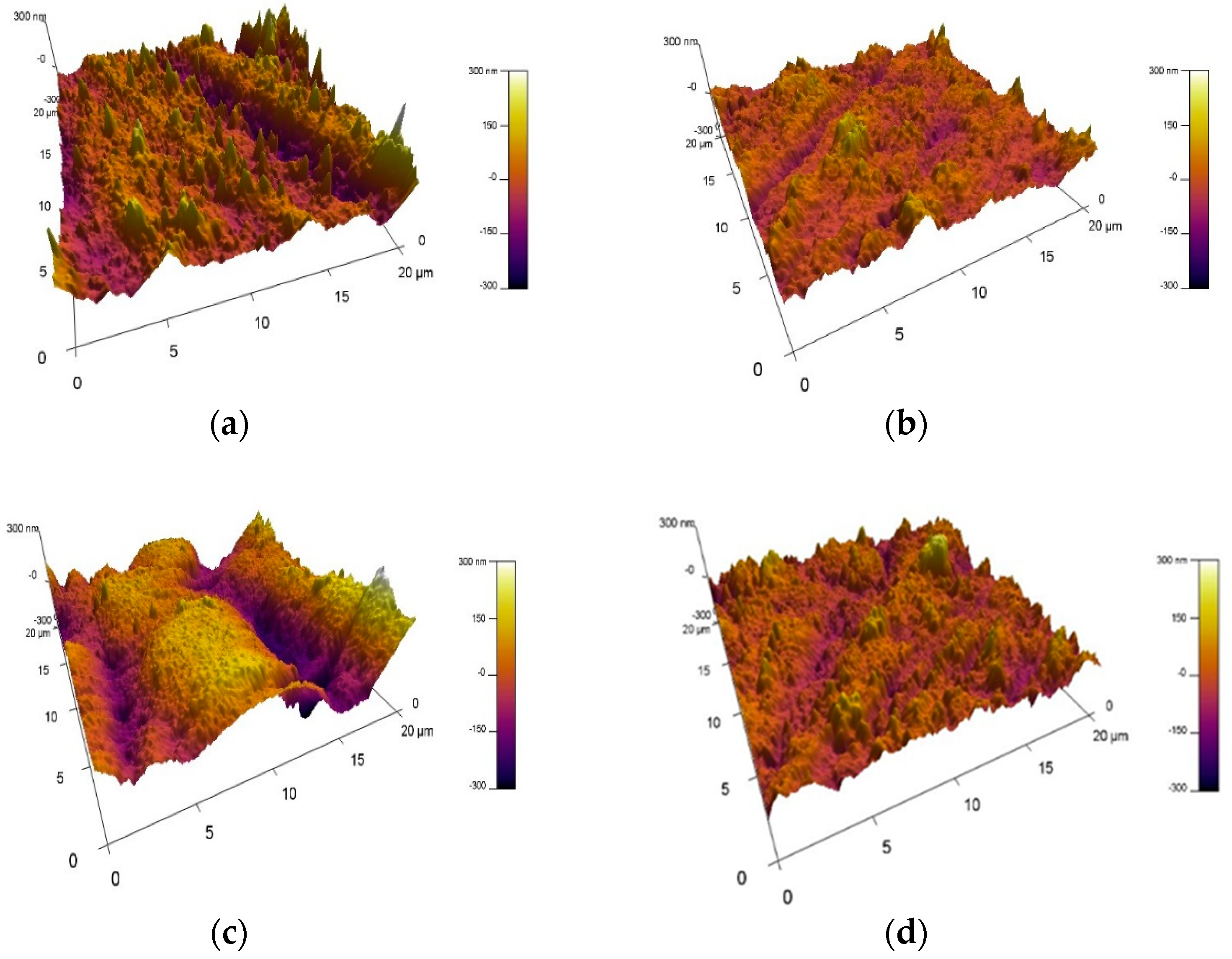
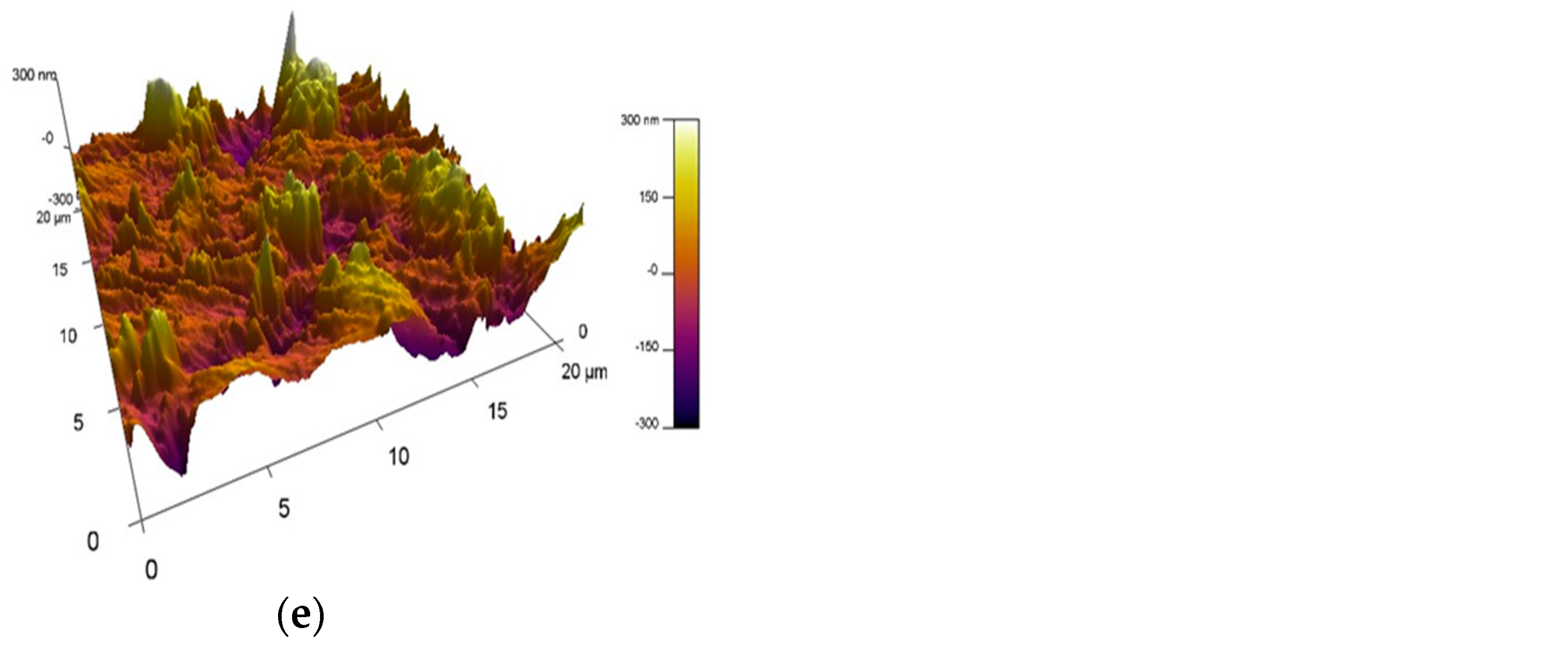
Three-dimensional AFM images of the ZrN coatings, deposited at different bias voltages on Ti6Al4V substrates, are shown in Figure 6. For comparison, the surface topography of the initial mechanically polished substrate is given to evaluate the effect of the bias voltages on the surface properties of the material. The nanoroughness of the bare substrate is 66 nm. Applying a bias voltage of −50 V to the substrate, the surface becomes smoother and the roughness decreases to 37 nm. Further increasing the bias voltage up to −110 V and −150 V leads to higher surface roughness of 51 nm and 75 nm as a result of the raised ion energy bombarding the surface. The higher the energy, the more Ar+ ions will bombard the substrate surface, and a re-sputtering effect is observed. These results are in agreement with those in Reference [41] where the correlation between the smoothness of the surface of the materials and bone cement was investigated. According to the authors in this study, the average surface roughness of 60–70 nm for ZrN coatings is close to that of “smooth” cemented orthopedic implants. On the other hand, higher surface roughness is related to larger contact area, which is of great significance for the cell adhesion, proteins adsorption, and biomineralization [42]. The researchers in [43] found out that the higher roughness of 16 nm corresponds to greater amount of attached cells and higher cell density compared to the smoother surface of 5 nm. The obtained results in our study have great importance for the manufacturing of implants in modern biomedical applications.

3.5. Wear Resistance

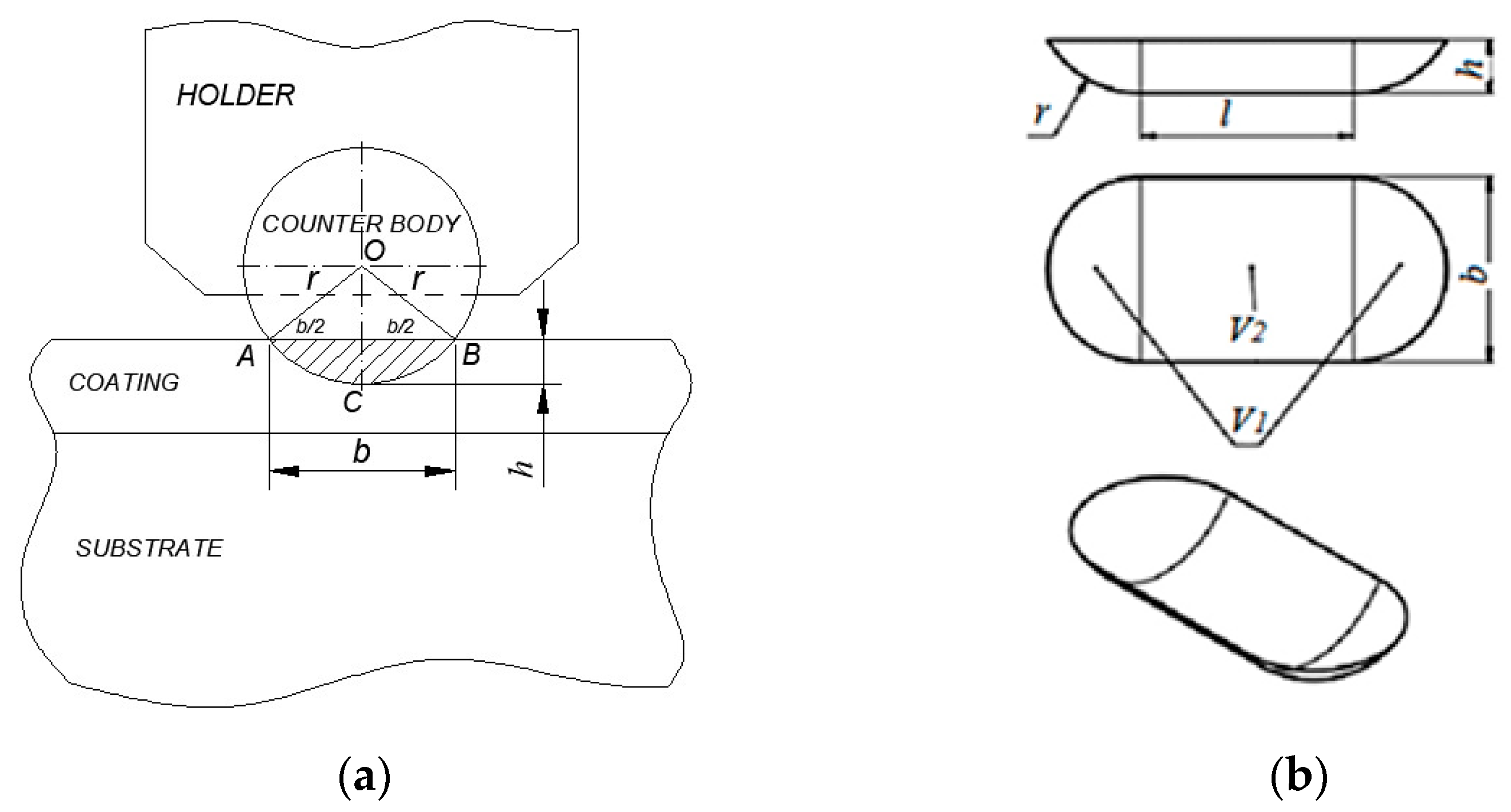
The wear resistance is an important factor for the durability and reliability of the implant. The wear resistance of the ZrN coatings, deposited at bias voltages of −50 V, −80 V, −110 V and −150 V on Ti6Al4V substrates by DC magnetron sputtering, was assessed by the “ball on flat sliding wear test” method with a horizontal orientation of the investigated specimen. Abrasive wear is performed by this method. It takes place when a hard surface with higher roughness slides across a surface that is softer. The abrasive wear is the loss of material by a rubbing or abrasive impact. It is usually caused by particles caught between the running elements. The intensity of abrasive wear depends primarily on the properties of the material. A ceramic ball of Al2O3 was used as a counter body, which was fixed in a holder. A specific load is applied to the ball with friction on the linear reciprocation drive sample. The friction scheme of the “ball on flat sliding wear test” method is shown in Figure 7. The wear channel on the surface is displayed in Figure 8.
The experiments were performed at a force of 0.5 N, a constant velocity of 10 mm/s and a sliding distance of 11 m, 13 m and 15 m. The wear rate of the coatings is estimated by Formula (1): [45]
V = V 1 + V 2 , m m 3
V1 is the volume of a segment of a sphere;
V2 is the volume of a segment of a cylinder.
The intensity of wear Iw is determined by the following dependence (2) [46]:
I w = V F × L , [ m m 3 ] N × m
V is the volume of the amount of material removed (trace) [mm3];
F is a normal load, [N];
L is the sliding distance relative to the counter body, [m].
The experiments were carried out using the following parameters of the tribological system: a constant load of 0.5 N and an average sliding speed of 10 mm/s. For all coatings, three tracks were performed at sliding distances of 11 m, 13 m and 15 m. The experimental results for the wear volumes of the coatings and the substrate, depending on the sliding distance, are exhibited in Table 1.
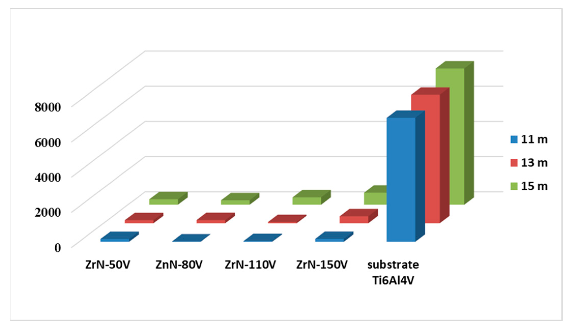
The graphic dependence on the wear volumes of the tracks in the ZrN coatings, deposited at different bias voltages and the substrate Ti6Al4V as a function of a sliding distance, is shown in Figure 9.
The obtained results for the wear intensity of the coatings at different bias voltages and the substrate as a function of sliding distance are shown in Table 2.
The graphic data about the wear intensity of the ZrN coatings and the substrate Ti6Al4V, depending on the sliding distance of the tracks, are given in Figure 10.
The experimental results show a significant influence of the sliding distance on the wear of the ZrN coatings deposited on Ti6Al4V substrates at various bias voltages. It can be seen from Figure 9 that the wear volume of coatings increases as the sliding distance increase. This dependence is kept for all coatings. The highest value of the wear volume is observed for the ZrN coating produced at −150 V and a sliding distance of 15 m, and the lowest one is for the ZrN coating deposited at −80 V and a sliding distance of 11 m. The main cause for wear rate is the friction. The surface roughness is related to the wear rate. The rougher the surface, the higher the size of the crystallites in the coating and the faster the wear. Therefore, the ZrN coating obtained at a bias voltage of −150 V would be worn faster than the other films due to its higher surface roughness of 75 nm. According to the authors in [40], the higher wear rate is associated with a significant plastic deformation, resulting in facile destruction of the protective surface film. It is obviously a gradual increase in the wear volume for all ZrN coatings at sliding distances of 11 m, 13 m and 15 m. No significant differences in the wear volume were observed for coatings fabricated at −50 V and −80 V at a distance of 13 m. The same trend is applied for the wear intensity of the ZrN coatings and the substrate as a function of sliding distance (Figure 10). On the other hand, the quality of the surface on which the coating is deposited also affects the intensity of wear. As the surface roughness increases, the intensity of wear enhances. These results are in good agreement with the ones obtained by the authors in [47]. This is explained by an increase in the area of engagement between the rubbing surfaces. The higher wear volume corresponds to the lower wear resistance of the coatings. It can be seen from Figure 8 and Figure 9 that the Ti6Al4V substrate has a remarkable wear volume and intensity, resulting in a poor wear resistance. One of the approaches for improving the material properties is the deposition of wear-resistant coatings. Based on the discussed results, it can be concluded that the reduction in the wear rate of the ZrN coatings proves the higher wear resistance of the coatings and makes them suitable for implants in biomedicine.

3.6. Corrosion Resistance

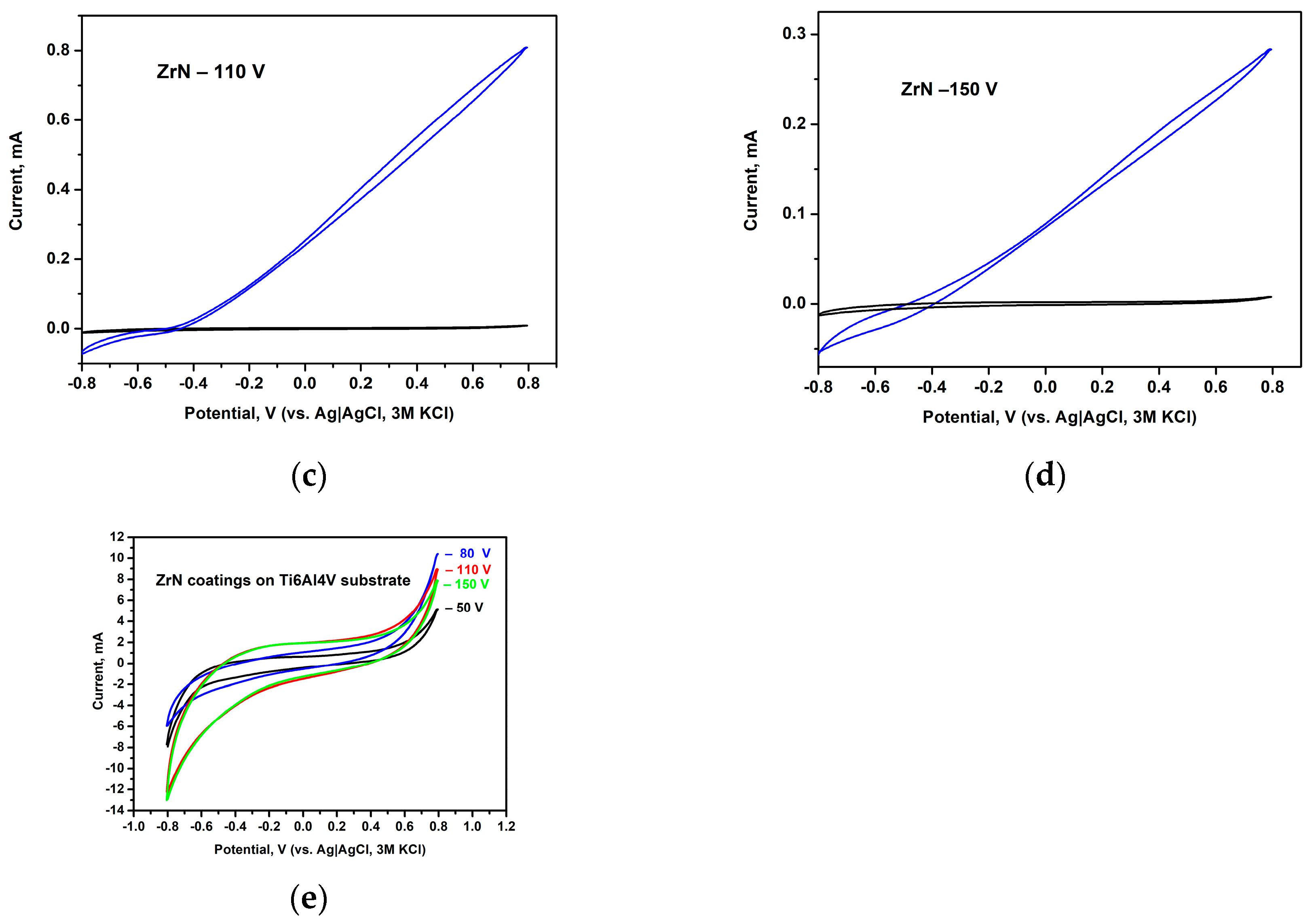
Cyclic voltammetry (CV) is a DC electrochemical technique that records the current value as a function of the potential that changes linearly with time from an initial to a final value and then back to the starting one. This potentiodynamic technique is routinely used to detect the existence of oxidative or reductive processes at the electrode–electrolyte interface. The polarization behavior of all ZrN samples was compared in both the absence and the presence of chloride ions as a strong corrosion agent (Figure 11). It can be seen that in the absence of Cl ions, there are no signs of oxidative processes (oxidation of metal surface with simultaneous metal dissolution—i.e., corrosion). Upon performing the study in an electrolyte containing NaCl close to the physiological concentrations, however, a sharp increase in the current was noticed at the negative polarization potential of −400 mV (vs. Ag/AgCl, 3 M KCl).
The current increase has the largest value for the sample ZrN coating for a bias voltage of −50 V, whilst the smallest one was noticed for ZrN film deposited at −150 V. The shape of cyclic voltammograms recorded for the later sample implies typically physical interfacial processes such as current increase as a consequence of the rise in applied potential in accordance with Ohm’s law, which is indicative of the absence of redox reactions (e.g., metal oxidation to soluble metal ions, known as metal corrosion). On the other hand, the CVs of the rest of the samples manifest two regions with different slopes, which is usually observed when a redox interaction between the electrolyte and the samples surfaces takes place.
Further studies, aiming at the characterization of corrosion protection of the samples ensured by the ZrN coating, were performed at equilibrium conditions with or without small perturbations (impedance studies and measurements of the open circuit potentials, OCP). Corrosion potentials of the samples were determined at open circuits, i.e., at no current flowing through the cell, until an equilibrium value is reached. Table 3 shows the measured OCP values, reported vs. a standard hydrogen electrode (SHE) determined in phosphate buffer, pH = 7.4 containing 0.1 M NaCl. The positive values of the OCPs found for ZrN coatings, produced at bias voltages of −50 V, −110 V and −150 V, indicate that these samples would not corrode even in chloride ions-containing solutions, whilst the ZrN sample, obtained at −80 V, shows some susceptibility to metal dissolution when exposed to chloride-containing solutions.
The equilibrium potential for the three samples discussed above is reached within 100–150 s, while the OCP of the second sample continuously decays over the same time period, as depicted in Figure 12.
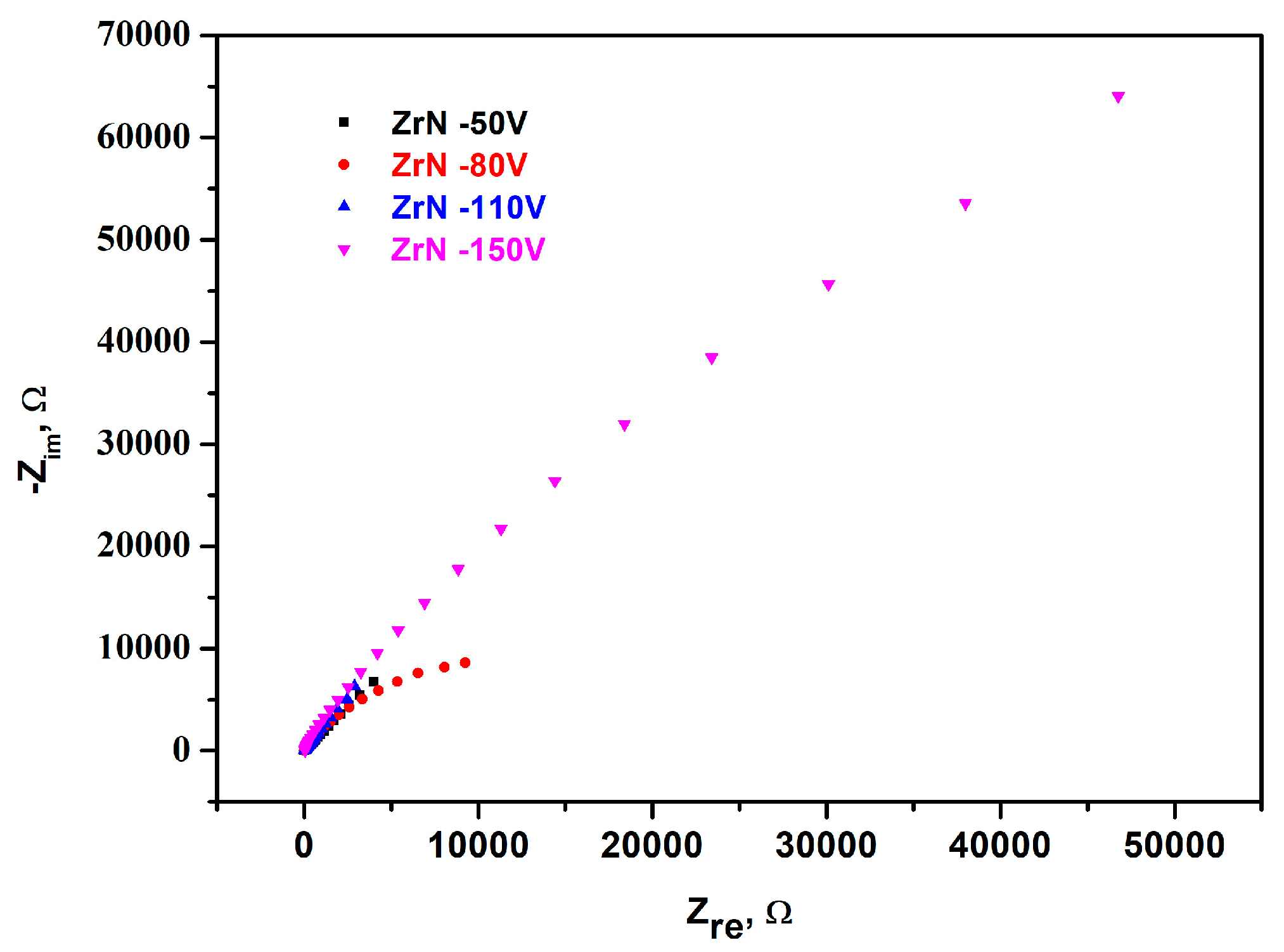
The above discussed findings of the corrosion resistance of the all investigated samples were confirmed by the EIS studies, as shown in Figure 13. The impedance spectra of the samples indicate the formation of a homogeneous protective layer over the metallic surface, as it can be deduced from the large semi-circle observed for sample, which was deposited at −150 V. EIS is an alternating current electrochemical technique that is used to study the sample’s behavior at the surface–solution interface in the presence of redox species. The appearance of semi-circles points toward the inability of redox species to reach the conductive surface to reduce or oxidize over it, and the semi-circle’s diameter rises with the density of the protective layer. Thus, the diameters of the semi-circles of the impedance spectra of the samples under study increase as the voltage of the magnetron sputtering decreases; thus, the ZrN coating obtained at −150 V possesses the highest protecting ability, as it can be deduced from the largest semi-circle diameter of the Nyquist plot. All the other studied samples provide much weaker corrosion protection to the metal substrate due to the much smaller charge transfer resistance manifested as drastically reduced semi-circle diameters.
The results obtained in our study exhibited a good possibility for deposition of the ZrN coatings on Ti6Al4V substrates at different bias voltages by the direct current magnetron sputtering technique. Increasing the bias voltage up to −150 V leads to an enhanced surface roughness of the coatings. The thickness influences the wear of the coating. When the coating is thicker, the wear takes longer. On one hand, a higher surface roughness would cause aggravation in the corrosion properties of the material, which is a serious issue for implant applications. One of the main problems is the release of metal ions which would lead to a lack of success in the implants and unwanted effects [48]. On the other hand, a higher surface roughness correlates with a larger contact area, which has great significance for materials applied as implants in biomedicine. A higher substrate bias voltage of −150 V corresponds to a higher value of surface roughness of 75 nm due to good adhesion between the substrate and the coating. This leads to an improvement in the corrosion resistance of the ZrN coating.

4. Conclusions

In the present investigation, we deposited ZrN coatings on Ti6Al4V substrates at bias voltages of −50 V, −80 V, −110 V and −150 V by the direct current magnetron sputtering method. XRD and FTIR analyses prove the growth of ZrN. The intensity of the diffraction peak of the Zr-N phase corresponding to the (1 1 1) crystallographic plane rises as the bias voltage increases. The ZrN coatings’ thickness reduces from 1.21 µm to 250 nm as the bias voltage enhances. The ZrN films’ surface roughness rises up to 75 nm at −150 V. Wear tests showed an increase in the wear rate and wear intensity as the bias voltage increased. Corrosion studies of the ZrN coatings were carried out by three electrochemical methods: open circuit potential (OCP), cyclic voltammetry (polarization measurements) and electrochemical impedance spectroscopy (EIS). All electrochemical measurements confirmed that the highest protection to corrosion is the ZrN coating, which was deposited on the Ti6Al4V substrate at a bias voltage of −150 V. It can be concluded that the applied technological conditions are suitable for the successful deposition of ZrN coatings as well for the enhancement of tribological and corrosion properties and their use as implants in modern biomedical applications.

Author Contributions

Conceptualization, S.R. and S.V.; methodology, S.R., D.D., N.I., N.D., V.S., V.K., V.R., T.I. and S.V.; formal analysis, S.R., D.D., N.I., N.D., V.S., V.K., V.R., T.I. and S.V.; investigation, S.R., D.D., N.I., N.D., V.S., V.K., V.R., T.I. and S.V.; writing—original draft preparation, S.R. and S.V.; writing—review and editing, S.R. and S.V. All authors have read and agreed to the published version of the manuscript.

Funding

This research received no external funding.

Institutional Review Board Statement

Not applicable.

Informed Consent Statement

Not applicable.

Data Availability Statement

Data are contained within the article.

Acknowledgments

Electrochemical studies were performed thanks to the research infrastructure of the Center for Competence “Personalized Innovative Medicine, PERIMED (BG Program “Science and Education for Smart Growth” grant BG05M2OP001-1.002-0005-C01)”. Research equipment of Distributed Research Infrastructure INFRAMAT, part of the Bulgarian National Roadmap for Research Infrastructures, supported by the Bulgarian Ministry of Education and Science, was used in this investigation. The authors thank student Georgi Kotlarski for visualization of the figures in the manuscript.

Conflicts of Interest

The authors declare no conflicts of interest.

References

  1. Chan, B.; Leong, K. Scaffolding in tissue engineering: General approaches and tissue-specific considerations. Eur. Spine J. 2008, 17, 467–479. [Google Scholar] [CrossRef] [PubMed]
  2. Ivanova, E.; Bazaka, K.; Crawford, R. 5-Metallic biomaterials: Types and advanced applications. In Metallic Biomaterial, 4th ed.; Biomaterials Science: Philadelphia, PA, USA, 2020; pp. 121–147. [Google Scholar]
  3. Han, X.; Ma, J.; Tian, A.; Wang, Y.; Li, Y.; Dong, B.; Tong, X.; Ma, X. Surface modification techniques of titanium and titanium alloys for biomedical orthopaedics applications: A review. Colloid Surf. B Biointerfaces 2023, 22, 11333. [Google Scholar] [CrossRef] [PubMed]
  4. Liu, X.; Chu, P.; Ding, C. Surface modification of titanium, titanium alloys, and related materials for biomedical applications. Mater. Sci. Engin. R Rep. 2004, 47, 49–121. [Google Scholar] [CrossRef]
  5. Raganya, M.; Moshokoa, M.; Obadele, B.; Olubambi, P.; Machaka, R. The microstructural and mechanical characterization of the β-type Ti-11.1Mo-10.8Nb alloy for biomedical applications. IOP Conf. Ser. Mater. Sci. Eng. 2019, 655, 012025. [Google Scholar] [CrossRef]
  6. Mohammed, M.; Khan, Z.; Siddiquee, A. Beta Titanium Alloys: The Lowest Elastic Modulus for Biomedical Applications: A Review. World Acad. Sci. Eng. Technol. Inter.J. Mater. Metal. Engin. 2014, 8, 822–827. [Google Scholar]
  7. Long, M.; Rack, H. Titanium alloys in total joint replacement—A materials science perspective. Biomaterials 1998, 19, 1621–1639. [Google Scholar] [CrossRef]
  8. Hanawa, T. Metal ion release from metal implants. Mater. Sci. Engin. C 2004, 24, 745–752. [Google Scholar] [CrossRef]
  9. Lepicka, M.; Gradzka-Dahlke, M. Surface modification of Ti6Al4V titanium alloy for biomedical applications and its effect on tribological performance—A review. Rev. Adv. Mater. Sci. 2016, 46, 86–103. [Google Scholar]
  10. Chou, W.; Yu, G.; Huang, J. Corrosion resistance of ZrN films on AISI 304 stainless steel substrate. Surf. Coat. Technol. 2003, 167, 59–67. [Google Scholar] [CrossRef]
  11. Sudderth, L.; Perez-Nunez, D.; Keiser, D.; McDevitt, S. Fabrication of ZrN barrier coatings for U-Mo microspheres via fluidized bed chemical vapor deposition using a metalorganic precursor. J. Nucl. Mater. 2018, 202, 81–93. [Google Scholar] [CrossRef]
  12. Tsai, C.; Hung, J.; Hu, Y.; Wang, D.; Pilliar, R.; Wang, R. Improving fretting corrosion resistance of CoCrMo alloy with TiSiN and ZrN coatings for orthopedic applications. J. Mech. Behav. Biomed. Mater. 2021, 114, 104233. [Google Scholar] [CrossRef] [PubMed]
  13. Roman, D.; Bernardi, J.; Amorim, C.; Souza, F.; Spinelli, A.; Giacomelli, F.; Carlos, A.; Baumvola, I.; Basso, R. Effect of deposition temperature on microstructure and corrosion resistance of ZrN thin films deposited by DC reactive magnetron sputtering. Mater. Chem. Phys. 2011, 130, 147–153. [Google Scholar] [CrossRef]
  14. Shaochen, L.; Jian, Z.; Ruihua, Z.; Shangchao, F.; Daqin, Y. Effects of sputtering pressure on microstructure and mechanical properties of ZrN films deposited by magnetron sputtering. Mater. Res. Bul. 2018, 105, 231–236. [Google Scholar]
  15. Kuznetsova, T.; Lapitskaya, V.; Khabarava, A.; Chizhika, S.; Warcholinski, B.; Gilewicz, A. The influence of nitrogen on the morphology of ZrN coatings deposited by magnetron sputtering. Appl. Surf. Sci. 2020, 522, 146508. [Google Scholar] [CrossRef]
  16. Larijani, M.; Tabrizi, N.; Norouzian, S.; Jafari, A.; Lahouti, S.; Hosseini, H.H.; Afshari, N. Structural and mechanical properties of ZrN films prepared by ion beam sputtering with varying N2/Ar ratio and substrate temperature. Vacuum 2006, 81, 550–555. [Google Scholar] [CrossRef]
  17. Zambrano, D.; Hernandez-Bravo, R.; Ruden, A.; Espinosa-Arbelaez, D.; Gonzalez-Carmona, J.; Mujica, V. Mechanical, tribological and electrochemical behavior of Zr-based ceramic thin films for dental implants. Ceram. Inter. 2023, 49, 2102–2114. [Google Scholar] [CrossRef]
  18. Vasylyev, M.; Mordyuk, B.; Sidorenko, S.; Voloshko, S.; Burmak, A.; Kruhlov, I.; Zakiev, V. Characterization of ZrN coating low-temperature deposited on the preliminary Ar+ ions treated 2024 Al-alloy. Surf. Coat. Technol. 2019, 361, 413–424. [Google Scholar] [CrossRef]
  19. Corona-Gomez, J.; Sandhi, K.; Yang, Q. Wear and corrosion behavior of nanocrystalline TaN, ZrN, and TaZrN coatings deposited on biomedical grade CoCrMo alloy. J. Mech. Behav. Biomed. Mater. 2022, 130, 105228. [Google Scholar] [CrossRef]
  20. Xin, Y.; Liu, C.; Huo, K.; Tang, G.; Tian, X.; Chu, P. Corrosion behavior of ZrN/Zr coated biomedical AZ91 magnesium alloy. Surf. Coat. Technol. 2009, 203, 2554–2557. [Google Scholar] [CrossRef]
  21. Chuan-Han, H.; Huan-Ping, T.; Fu-Hsing, L. Formation of zirconia coatings on ZrN-coated substrates by plasma electrolytic oxidation. Surf. Coat. Technol. 2015, 269, 295–301. [Google Scholar]
  22. Xiaogang, Z.; XiaoXu, Y.; Feifei, X.; Kwang-Ho, K.; Zhigang, S. Influence of substrate bias on microstructure and morphology of ZrN thin films deposited by arc ion plating. Trans. Nonfer. Met. Soc. China 2012, 22, s115–s119. [Google Scholar]
  23. Azibi, M.; Saoula, N.; Aknouche, H. The influence of substrate bias voltage on the electrochemical properties of ZrN thin films deposited by radio-frequency magnetron sputtering: Biomedical application. J. Electr. Engin. 2019, 70, 112–116. [Google Scholar] [CrossRef]
  24. Brunello, G.; Brun, P.; Gardin, C.; Ferroni, L.; Bressan, E.; Meneghello, R.; Zavan, B.; Sivolella, S. Biocompatibility and antibacterial properties of zirconium nitride coating on titanium abutments: An in vitro study. PLoS ONE 2018, 13, e0199591. [Google Scholar] [CrossRef] [PubMed]
  25. Slate, A.; Wickens, D.; Mohtadi, M.; Dempsey-Hibbert, N.; West, G.; Banks, C.; Whitehead, K. Antimicrobial activity of Ti-ZrN/Ag coatings for use in biomaterial applications. Sci. Rep. 2018, 8, 1497. [Google Scholar] [CrossRef]
  26. Oganyan, M.; Vereschaka, A.; Volosova, M.; Gurin, V. Influence of the application of wear-resistant coatings on force parameters of the cutting process and the tool life during end milling of titanium alloys. Mater. Today Proc. 2021, 38, 1428–1432. [Google Scholar] [CrossRef]
  27. Kowalski, S.; Cygnar, M.; Cieślikowski, B. Analysis of the application of ZrN coatings for the mitigation of the development of fretting wear processes at the surfaces of push fit joint elements. Proc. Inst. Mechan. Engin. Part J. J. Engin. Tribol. 2019, 234, 1208–1221. [Google Scholar] [CrossRef]
  28. Chang, Y.; Wu, C. Mechanical properties and impact resistance of multilayered TiAlN/ZrN coatings. Surf. Coat. Technol. 2013, 231, 62–66. [Google Scholar] [CrossRef]
  29. Rabadzhiyska, S.; Kotlarski, G.; Shipochka, M.; Rafailov, P.; Ormanova, M.; Strijkova, V.; Dimcheva, N.; Valkov, S. Duplex Surface Modification of 304-L SS Substrates by an Electron-Beam Treatment and Subsequent Deposition of Diamond-like Carbon Coatings. Coatings 2022, 12, 401. [Google Scholar] [CrossRef]
  30. Guo, Z.; Ma, D.; Zhang, X.; Li, J.; Feng, J. Preparation and toughening of a-Cur/c-ZrN nano-multilayer hard coatings. Appl. Surf. Sci. 2019, 483, 432–441. [Google Scholar] [CrossRef]
  31. Meng, Q.; Wen, M.; Qu, C.; Hu, C.; Zheng, W. Preferred orientation, phase transition and hardness for sputtered zirconium nitride films grown at different substrate biases. Surf. Coat. Technol. 2011, 205, 2865–2870. [Google Scholar] [CrossRef]
  32. Singh, A.; Kuppusami, P.; Khan, S.; Sudha, C.; Thirumurugesan, R.; Ramaseshan, R.; Divakar, E.; Mohandas, S. Dash, Influence of nitrogen flow rate on microstructural and nanomechanical properties of Zr-N thin films prepared by pulsed DC magnetron Sputtering. Appl. Surf. Sci. 2013, 280, 117–123. [Google Scholar] [CrossRef]
  33. Kumar, D.; Kaliaraj, G. Multifunctional zirconium nitride/copper multilayer coatings on medical grade 316 L SS and titanium substrates for biomedical applications. J. Mechan. Behav. Biom. Mater. 2018, 77, 106–115. [Google Scholar] [CrossRef] [PubMed]
  34. Gudmundsson, J.; Brenning, N.; Lundin, D.; Helmersson, U. High power impulse magnetron sputtering. J. Vac. Sci. Technol. A 2012, 30, 030801. [Google Scholar] [CrossRef]
  35. Devia, D.; Velez, J.; Parra, E. Bias voltage influence on the mechanical and tribological properties of titanium aluminum nitride coatings produced by triode magnetron sputtering. Rev. Matér. 2015, 20, 115–126. [Google Scholar]
  36. Detorhodge, A.; Chason, A. Stress and microstructure evolution of thick sputtered films. Acta Mater. 2009, 57, 2055–2065. [Google Scholar]
  37. Ehiasarian, A.; Wen, J.; Petrov, I. Interface microstructure engineering by high power impulse magnetron sputtering for the enhancement of adhesion. J. Appl. Phys. 2007, 101, 054301. [Google Scholar] [CrossRef]
  38. Caicedo, A.; Bejarano, J.; Gomez, G.; Prieto, M.; Cortéz, C.; Muñoz, J. Nanostructured multilayers of TiN/ZrN obtained by magnetron sputtering. Phys. Status Solidi 2007, 4, 4127–4133. [Google Scholar] [CrossRef]
  39. Khan, S.; Mehmood, M.; Ahmad, I.; Ali, F.; Shah, A. Structural and electrical resistivity characteristics of vacuum arc ion deposited zirconium nitride thin films. Mater. Sci. Semic. Process. 2015, 30, 486–493. [Google Scholar] [CrossRef]
  40. Makino, Y.; Mori, M.; Miyake, S.; Saito, K.; Asami, K. Characterization of Zr–Al–N films synthesized by a magnetron sputtering method. Surf. Coat. Technol. 2005, 193, 219–222. [Google Scholar] [CrossRef]
  41. Hirata, M.; Oe, K.; Kaneuji, A.; Uozu, R.; Shintani, K.; Saito, T. Relationship between the surface roughness of material and bone cement: An increased “polished” stem may result in the excessive taper-slip. Materials 2021, 14, 3702. [Google Scholar] [CrossRef]
  42. Mendonça, G.; Mendonça, D.; Aragao, F.; Cooper, L. Advancing dental implant surface technology—From micron- to Nanotopography—Review. Biomate. 2008, 29, 3822–3835. [Google Scholar] [CrossRef] [PubMed]
  43. Zhou, W.; Zhong, X.; Wu, X.; Yuan, L.; Zhao, Z.; Wang, H.; Xia, Y.; Feng, Y.; He, J.; Chen, W. The effect of surface roughness and wettability of nanostructured TiO2 film on TCA-8113 epithelial-like cells. Surf. Coat. Technol. 2006, 200, 6155–6160. [Google Scholar] [CrossRef]
  44. Rupetsov, V. Increasing the Wear Resistance of Details and Tools of Production Equipment; ZEA-Print: Smolyan, Bulgaria, 2018; pp. 59–61. [Google Scholar]
  45. Rupetsov, V. Experimental test stand for the study of coatings resistance. J. Food Packag. Sci. Techn. Technol. 2014, 1, 60–65. [Google Scholar]
  46. Mishra, A. Analysis of relation between friction and wear. Inter. J. Mechan. Engin. Robot. 2014, 1, 603–606. [Google Scholar]
  47. Hadinezhad, M.; Elyasi, M.; Rajabi, M.; Abbasi, M. Study of the Effects of Slip Distance and Surface Roughness on Wear Rate. Manuf. Sci. Technol. 2015, 3, 146–154. [Google Scholar] [CrossRef]
  48. Ibrahim, M.; Sarhan, A.; Yusuf, F.; Hamdi, M. Biomedical materials and techniques to improve the tribological, mechanical and biomedical properties of orthopedic implants-A review article. J. Alloys Comp. 2017, 714, 636–667. [Google Scholar] [CrossRef]
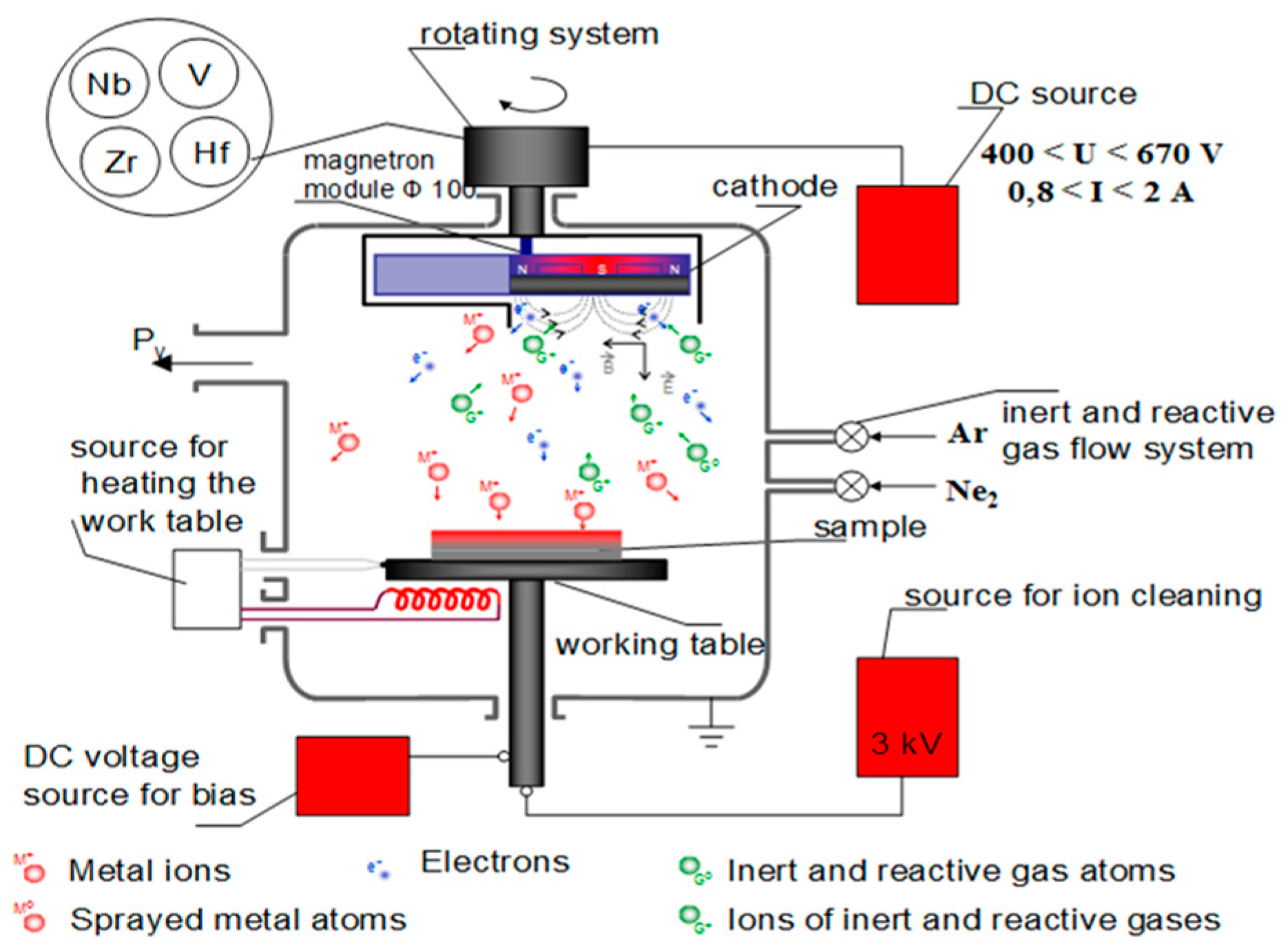
Figure 1. A principle scheme of the direct current magnetron sputtering process.
Coatings 14 01434 g001
Figure 2. XRD patterns of the ZrN coatings deposited at different bias voltages.
Coatings 14 01434 g002
Figure 3. FTIR reflectance spectra of ZrN films deposited at different bias voltages.
Coatings 14 01434 g003
Figure 4. FTIR absorbance spectra of ZrN films as a function of bias voltages.
Coatings 14 01434 g004
Figure 5. SEM images of (a) ZrN coatings produced at a bias voltage of −50 V; (b) ZrN films obtained at a bias voltage of −110 V; (c) chemical composition of ZrN coatings on Ti6Al4V substrates by EDX analysis.
Coatings 14 01434 g005
Figure 6. Three-dimensional AFM images of the surface topography of (a) bare substrate Ti6Al4V and ZrN coatings, deposited at bias voltages of (b) −50 V; (c) −80 V; (d) −110 V; (e) −150 V.
Coatings 14 01434 g006aCoatings 14 01434 g006b
Figure 7. A friction scheme of “ball on flat sliding wear test”: method 1—sample; 2—test ball.
Coatings 14 01434 g007
Figure 8. (a) A general scheme of “ball-on-plate” method; (b) wear channel on the surface of the test sample [44].
Coatings 14 01434 g008
Figure 9. Wear volumes of the tracks for ZrN coatings obtained at different bias voltages from the Ti6Al4V substrate at different sliding distances.
Coatings 14 01434 g009
Figure 10. Wear intensity of the ZrN coatings and the substrate Ti6Al4V at different track sliding distances.
Coatings 14 01434 g010
Figure 11. Polarization studies (CVs) of the ZrN films: (a) at −50 V; (b) −80 V; (c) −110 V; (d) −150 V, recorded in the absence (black solid curves) and the presence (blue solid curves) of 0.1 M NaCl; electrolyte—0.1 M phosphate buffer, pH = 7.4; reference electrode Ag/AgCl, 3 M KCl, room temperature; (e) a general scheme of all ZrN films at different bias voltages.
Coatings 14 01434 g011aCoatings 14 01434 g011b
Figure 12. Open circuit potential of the 4 samples measured in the presence of 0.1 M NaCl against a Ag/AgCl, 3 M KCl reference system. During measurements, only the ZrN-coated side was in contact with the solution.
Coatings 14 01434 g012
Figure 13. EIS spectra (Nyquist plots) of the 4 samples recorded in 0.1 M KCl containing 10 mM K4Fe(CN)6/K3Fe(CN)6 as redox probe. During measurements, only ZrN-coated substrate was exposed to the solution.
Coatings 14 01434 g013
Table 1. Wear volumes of the tracks in the ZrN coatings, deposited at different bias voltages and the substrate Ti6Al4V as a function of sliding distance.
Sliding Distance, mTi6Al4VZrN−50 VZrN−80 VZrN−110 VZrN−150 V
1138,780892119246925
1345,518115711874582586
1558,1202339190231425146
Table 2. Wear intensity of the ZrN coatings, deposited at different bias voltages and the substrate Ti6Al4V at various sliding distances.
Sliding Distance, mTi6Al4VZrN−50 VZrN−80 VZrN−110 VZrN−150 V
1170511622145168
13731017818270398
157749312253418686
Table 3. Equilibrium potentials of the ZrN-coated Ti6Al4V samples, measured in phosphate buffer, pH = 7.4 containing 0.1 M NaCl.
NoSampleOCP Measured in the Presence of 0.1 M NaCl
1ZrN−50 V168 mV
2ZrN−80 V−90 mV
3ZrN−110 V93 mV
4ZrN−150 V372 mV
Disclaimer/Publisher’s Note: The statements, opinions and data contained in all publications are solely those of the individual author(s) and contributor(s) and not of MDPI and/or the editor(s). MDPI and/or the editor(s) disclaim responsibility for any injury to people or property resulting from any ideas, methods, instructions or products referred to in the content.