Abstract
Due to the large number of defects at the grain boundaries of nanocomposites, defects have a significant effect on the physico-chemical properties of a material. Therefore, controlling the charging behaviour of functional nanocomposites in a non-contact manner with a light field can improve their physical and chemical properties. Chitosan-derived carbon dots were synthesised by exploiting the abundant N element in chitosan. In order to passivate the defects of chitosan-derived carbon dots, a MoO3/carbon dot nanocomposite was constructed in this study to tailor the band gap and improve the extraction ability of carriers through light induction. The results showed that the strong interfacial interaction between MoO3 and carbon dots enhanced the optical absorption and interfacial charge transfer in the visible and some near-infrared regions. The resulting MoO3/carbon dot heterostructure was coated on A4 printing paper, and electrodes were integrated in the coating film. The photocurrent signals of the thick film were investigated using 405, 532, 650, 808, 980 and 1064 nm light sources. The results indicated that the phenomenon of photocurrent switching to the visible light and some near-infrared light regions was observed. The charge carrier extraction ability of the MoO3/carbon dot nanocomposite through light triggering was much better than that of chitosan-derived carbon dots. The on/off ratio and response speed of the MoO3/carbon dot nanocomposite were significantly improved. The physical mechanism was discussed based on the ordered and disordered structures of polymer-derived carbon nanomaterials. This material could be applicable to the development of broadband flexible photosensors, artificial vision or light-utilising interdisciplinary fields.
1. Introduction
Among metal oxides, molybdenum trioxide is one of the most important n-type semiconductors with a wide band gap (about 2.8–3.6 eV or so), high carrier mobility and excellent stability. Heavily doped MoO3 or oxygen vacancy-tailored MoO3−x has good plasmonic properties, which can promote interfacial charge transfer through light excitation. MoO3-based nanocomposites have been extensively studied in batteries [1,2,3], memristors [4,5], photocatalytic H2 evolution [6,7], nanohybrid-based biosensors [8], gas sensors [9,10,11], supercapacitors [12,13], electrochromic devices [14] and so on. Regarding the modification of MoO3 and its nanocomposites, most of research is focused on oxygen vacancy tailoring, metal or non-metal element doping [15,16], interfacial optimisation of different components, mixed dimensionality and multi-phases in nanocomposites to enhance multifunctionality and broaden applications [17,18,19,20,21,22,23,24,25].
In order to tailor the band gap width of MoO3 or to improve the properties of MoO3-based nanocomposites, several methods are widely used, such as oxygen vacancy tailoring [26,27,28,29]; heterojunction construction [30,31]; intercalation [32]; and surface, interface and defect engineering. In the field of multifunctional materials and devices, MoO3 was used in organic light-emitting devices [33]. The current extraction capability of ZnO/PbS quantum dot heterojunctions was improved using MoO3 as an interfacial layer in photovoltaic devices [34]. The work function of MoO3−x films was tuned using oxygen plasma treatment [35]. N-type doping in MoO3 was performed [36]. High mobility transport anisotropy in few-layer MoO3 was reported [37]. The interfacial interaction of MoO3/CH3NH3PbI3−xClx was studied [38]. The stability of organic thin-film transistor was improved by preventing MoO3 diffusion with a metal/MoO3/organic multilayer interface [39]. The photochromic behaviour of ZnO/MoO3 interfaces was studied [40]. A sulphur-doped molybdenum oxide interface was used for organic solar cells [41]. Liu and co-workers [42] provided new insights into planar defects in layered α-MoO3. The structural transformation and electrical transport of MoO3 nanobelts to MoO2 nanorods were studied [43]. The effects of moisture on the energy level alignment at MoO3/organic interfaces were studied [44].The phase transformation of hexagonal MoO3 to layered MoO3 was studied [45]. The effects of halogen and surface defects on the decomposition of organic perovskite on MoO3 were studied [46]. The oxygen vacancy-induced band engineering of MoS2/MoO3 was studied [47]. The atomic scale mechanisms of MoS2 oxidation process for kinetic control of MoS2/MoO3 interfaces were reported [48]. The atomic rearrangement and amorphisation induced by carbon dioxide in two-dimensional MoO3-x nanomaterials were studied [49]. The diverse applications of MoO3 in organic photovoltaics were presented [50]. The synthesis and defect engineering of molybdenum oxides were carried out [51]. Sunlight-induced photothermal synergistic CO2 conversion via localised surface plasmon resonance of MoO3−x was reported [52]. Defect-enriched MoO3−x nanosheets were synthesised [53]. A single sea urchin MoO3 nanostructure was synthesised to demonstrate surface enhancement with Raman spectroscopy [54]. High-surface-area plasmonic MoO3−x was synthesised [55]. Centimetre-scale single-crystal α-MoO3 was obtained [56], which was used in synaptic devices. Lin and co-workers [57] studied the band structure tuning of α-MoO3 via tin intercalation. The plasmonic and amorphous effects in MoO3−x spheres were integrated for photoelectrochemical water oxidation [58]. The defect-induced surface-enhanced Raman scattering of MoO3−x thin films via thermal treatment was reported [59]. Oxygen-deficient MoO3−x nanosheets were synthesised through light irradiation [60]. The sulphurisation process of planar MoO3 was carried out [61], and the Raman response was enhanced.
By reviewing progress in MoO3-based nanocomposites, it was found that most of the research on MoO3 generally uses defect engineering, doping, interfaces and construction of heterostructures [2,3,12,14,15,17,18,19,20,21,22,23,24,25,26,27,28,29,30,31,34,38,39,40,41,51,53]. Several other materials, such as metal oxides, metal sulphides, metals, carbon nanomaterials, etc., have been used in the fabrication of MoO3-based heterojunctions. Among these materials, MoO3/carbon nanocomposites are attractive due to the good conductivity of carbon nanomaterials, which is favoured in charge carrier transfer at the interface between MoO3 and carbon nanomaterials, presenting applications in interdisciplinary fields.
Among carbon nanomaterials, carbonised polymer dots (CPDs) are particularly attractive in the polymer field, as CPDs are usually hybrid nanostructures. The effects of their aggregation state on the properties are significant. Meanwhile, a large number of defects of carbonised polymer dots result in rather difficult extraction of carriers [62]. Polymer carbon dots are a type of typical clusters that combine crystalline state and amorphous state. A great advantage of polymer-derived carbon dots is the diversification of material design and low cost. Meanwhile, doping with heteroatoms containing lone electron pairs makes bandgap tailoring easy [63].
To date, the synthesis of carbonised polymer dots can be carried out using a variety of polymers [64]. To improve the fluorescence properties, regulating the surface state of carbon nanomaterials [65], increasing the crosslinking degree of polymers [66,67] and increasing the conjugation degree of carbonised polymer dots [68,69] have been widely accepted. Most of the research on carbon dots has focused on the visible light region [62,64]. The near-infrared properties are also of great interest [70]. Recently, aggregation-induced luminescence has been one of the hot topics. The relationship between the aggregation state and the fluorescence properties of polymer-derived carbon dots has been extensively studied [71]. The phosphorescence of carbon dots was obtained by inducing the structure of the polymer [72]. Since a variety of polymer materials can be used in the synthesis of polymer-derived carbon dots, some chemical groups in polymers strongly affect the aggregation state structures and the properties of polymer-derived carbon dots. The investigation of the physical mechanism and properties is still a great challenge. The evolution process and synthesis methods of carbon dots and polymer-derived dots were recently reviewed [73]. Function-driven precursors were selected for the synthesis of carbon dots [74]. The formation mechanism of carbon dots used with aromatic compounds was also reviewed [75].
Regarding the research on the physical properties of carbon dots, most of the studies have focused on the photoluminescence properties and their photodynamic mechanism process [62,63,64,65,66,67,68]. Since photoluminescence, the non-radiative energy consumption process and free electron/hole generation are three competitive processes in photodynamics, to suppress non-radiative energy consumption and improve the graphitisation degree and conjugation degree of polymer-derived carbon dots, the optoelectronic property would also need to be improved by improving the separation and transfer of electrons and holes through light triggering. Therefore, the photocurrent signal could be enhanced by suppressing the non-radiative energy consumption of carbon dots.
In previous studies, Ma’s group focused on the gas sensitivity of organic/inorganic hybrids [76]. As many nanocomposites exhibit controlled multifunctionality, multiple physical mechanisms coexist, leading to interdisciplinary applications. This greatly stimulated the interest of Ma. In the last decade, the focus of Ma and co-workers [77] has shifted to studies on the photoconductive behaviour of nanocomposites in broadband light spectral regions and their microstructures based on the control of microstructures, interfaces and the defect engineering of nanocomposites.
It is well known that narrowing the bandgap of wide-bandgap metal oxides is very useful to exploit the broadband light sources in interdisciplinary fields. Among the methods to tailor the band gap of metal oxides, C and N element doping or multi-element co-doping has been widely used. Even after 20 years of research, increasing the C and N doping contents is still a major challenge. Polymer-derived carbon dots contain high C and controlled N element contents. Therefore, wide band gap metal oxides modified via polymer-derived carbon dots would be effective and simple.
To passivate the electronic traps of chitosan-derived carbon dots, a MoO3/carbon dot heterojunction was constructed to enhance separation and charge transfer. On the other hand, in previous studies, Ma and co-workers [77] used Au gap electrodes on polyethylene terephthalate film to study photocurrent signals. In the field of flexible device design, in addition to PET (polyethylene terephthalate) film, polyimide, printing paper and various fibres are often used as flexible substrates. In this paper, A4 printing paper was used as a substrate to investigate the photocurrent signal of the resulting nanocomposite due to its low cost. Compared with PET film, the main composition of A4 paper is plant fibre, including cellulose, hemicellulose and lignin. These components contain a large number of groups containing the oxygen element, and these groups could trap the photoexcited carriers. Therefore, the improvement in carrier extraction ability with a paper substrate is still meaningful and a great challenge. Herein, the photocurrent extraction abilities of MoO3/carbon dots nanojunctions were investigated using low-power 405, 532, 650, 808, 980 and 1064 nm light excitation. The resulting heterostructure showed good photocurrent signals in a wide range of the light spectrum. Further, since there are many ways to passivate the defects of nanocomposites based on their interfacial electronic interactions, carbon nanofibre was derived using carboxymethyl cellulose under a similar reaction condition, and the interaction between carbon nanofibre and Cu nanoparticles was studied for defect passivation, because Cu nanoparticles are electron-rich materials [77]. In another previous report [78], a ZnO/MnSx nanojunction was constructed to narrow the bandgap of wide-bandgap materials, which showed that the absorption of the resulting nanocomposite was extended to part of the NIR region due to the introduction of an impurity level or defect level. Photocurrent signals were obtained from the visible light region to part of the NIR. In this work, carbon dots were obtained with chitosan as a precursor due to the self-N-doping characteristics, and the interfacial interaction of MoO3/carbon dots was studied. Some significant results were also obtained. Based on the simple, effective, green chemical synthesis and low cost of carbon nanomaterials, these investigated results also have some reference value for interdisciplinary applications or exploring the mechanism of photodynamic and light–matter interaction.
2. Materials and Methods
2.1. Materials
Sodium molybdate dihydrate (analytical reagent (AR)), Sinopharm Chemical Reagent Co., Ltd. (Shanghai, China). Citric acid (AR), Tianjin Ruijin Chemical Reagent Co., Ltd. (Tianjin, China). Chitosan (AR; the degree of deacetylation was greater than 90%), Shanghai Blue Season Technology Development Co., Ltd. (Shanghai, China). Hydrochloric acid (AR), Hongteng Weiye new Material Co., Ltd. (Yantai, China).
2.2. Preparation of Carbon Dots with Chitosan Carbonization
The synthesis process and reaction conditions of carbon dots with chitosan carbonisation are similar to our previous report [77]. The only difference is the use of chitosan as a precursor in this study. In the reference [77], another polymer is used as a precursor.
2.3. Preparation of MoO3 and MoO3/Carbon Dots Derived from Chitosan
First, 30 mL of concentrated hydrochloric acid and 1000 mL of H2O were added to a 1200 mL glass container to obtain diluted hydrochloric acid for later use.
A volume of 20 mL of H2O, 40 mL of diluted hydrochloric acid and 1 g of sodium molybdate were added and stirred for 5–10 min. The hydrothermal reaction conditions and sample treatment were the same as in our previous report [77].
Similarly, 10 mL of chitosan-derived carbon dot suspension, 10 mL of H2O, 40 mL of dilute hydrochloric acid and 1 g of sodium molybdate were added and stirred for 5–10 min. The hydrothermal reaction conditions and sample treatment were the same as in our previous report [77].
2.4. Characterization of SEM, EDS Mapping, TEM, UV-Vis-NIR, XRD and Raman Spectra
The characterisation of SEM (scanning electron microscope), TEM (transmission electron microscope), UV-Vis-NIR (UV-VIS-NIR spectrophotometer) and XRD (X-ray powder diffraction) were the same as in our previous report [77]. The instruments used were ZEISS Gemini SEM300 (Oberkohen, Germany), JEM-1011 (Nippon Electronics Co., Ltd., Tokyo, Japan), TU-1810 spectrophotometer (Shanghai Yuan Analysis Instrument Co., Ltd., Shanghai, China) and XRD-7000 from SHIMADZU (Shimadzu, Kyoto, Japan). Energy dispersive spectroscopy (EDS Mapping) measurements were performed using a Hitachi S-4800 (HITACHI, Tokyo, Japan).
The characterisation of Raman spectra was as follows: The sample suspension was poured onto the glass substrate and dried at room temperature. The determination of Raman spectra was performed using a PHS-3C confocal Raman spectrometer (HORIBA, Kyoto, Japan). The operating wavelength and power density of the laser radiation were 633 nm and 17 mW, respectively.
2.5. Photocurrent Response of Nanocomposite to Visible Light and Part of NIR
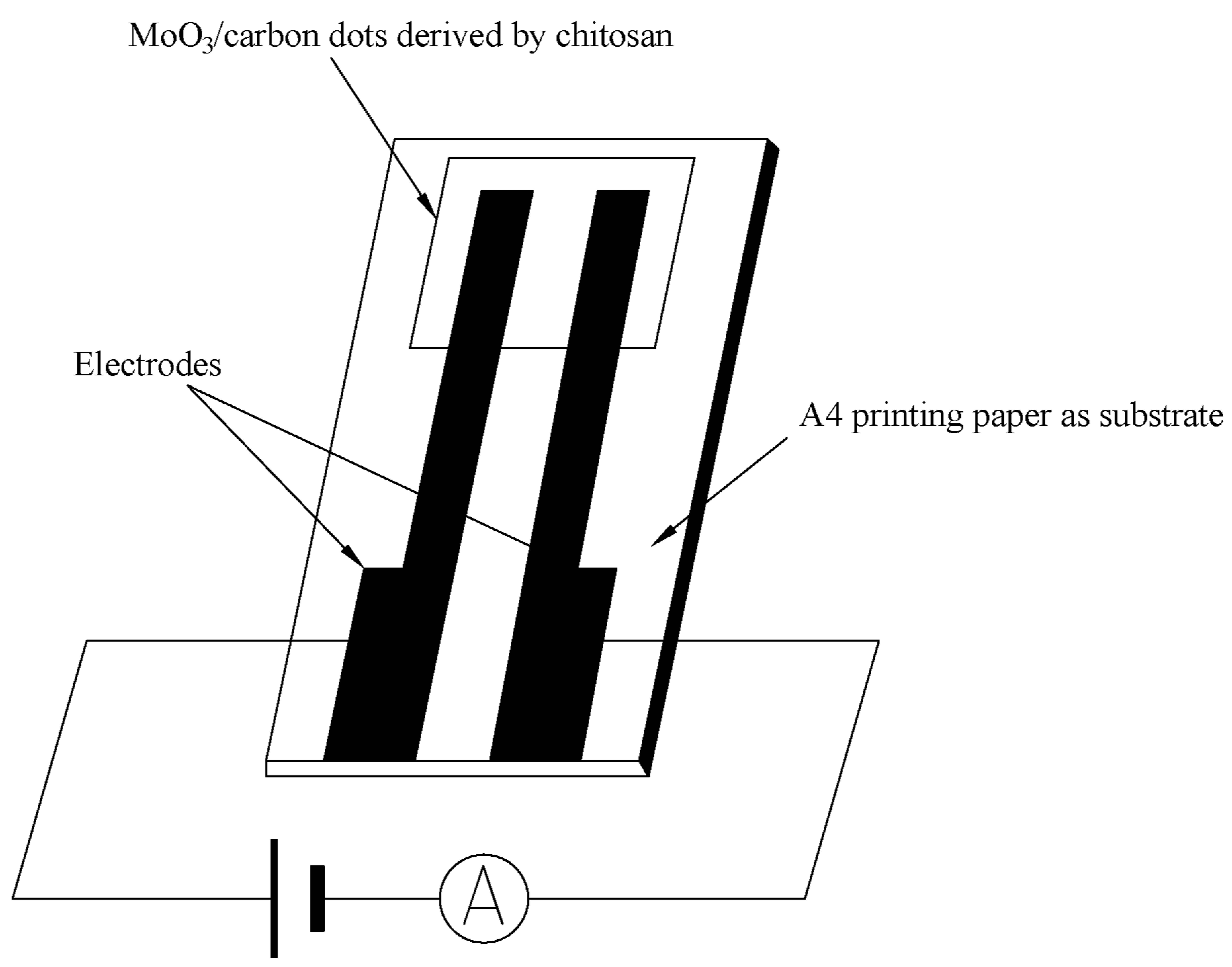
The photocurrent signal measurement of the resulting nanocomposite in the visible light and part of the NIR was similar to our previous report [77]. The difference in this study is that A4 printing paper was used as the substrate, and several Ag fibres were attached to the film (using conductive adhesive) as electrodes (Au gap electrodes on PET film in previous publications). The structure of the electrodes is shown in Scheme 1. The photoconductive response to weak visible light (40 W) or 405, 532 and 650 nm (100, 50, 5 mW) and 808, 980 and 1064 nm NIR with low power (10, 40, 50, 100, 200 mW) was determined using an LK2000A Electrochemical Work Station (LANLIKE Chemistry and Electron High Technology Co., Ltd. (Tianjin, China)) with 1 V DC bias applied, and the current of the thick film was determined through computer recording before and after irradiation of light sources.
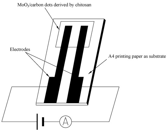
Scheme 1.
The structure of electrodes in the experiment.
3. Results and Discussion
Since chitosan has some amino groups and hydroxyl groups, in order to improve the polycondensation degree and crosslinking degree of polymer carbon dots, a certain amount of citric acid was added as a crosslinking agent in the process of hydrothermal carbonisation of chitosan. In general, chitosan-derived carbon dots are N element self-doped carbon materials. The contribution of N element doping to the functional properties of carbon dots is significant due to the increase in the degree of electron delocalisation. The lone electron pair of the N element also participated in the photodynamic process. This naturally increased the chances of photoexcitation, transition and recombination. Otherwise, the properties of nanomaterials are highly dependent on the morphology, dimension and size of the materials. Therefore, the morphology of chitosan-derived carbon nanomaterials was investigated. A representative TEM image of chitosan-derived carbon dots is shown in Figure 1.
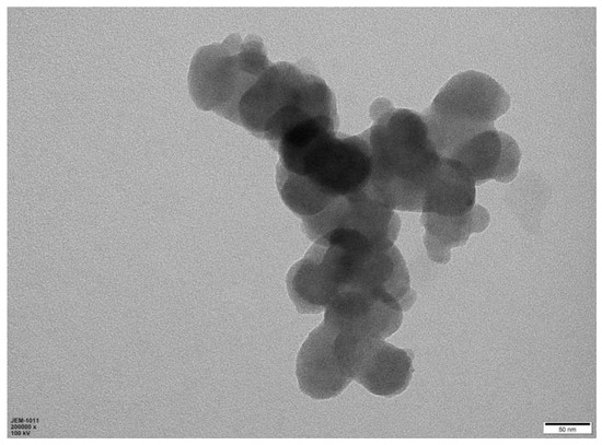
Figure 1.
TEM (transmission electron microscope) image of chitosan-derived carbon dots.
As shown in Figure 1, the carbon nanomaterials synthesised using chitosan as a precursor showed nanoparticle morphology. The diameter of these particles was approximately in the range of 20–30 nm. This morphology is different from that obtained using carboxymethyl cellulose as a precursor under similar reaction conditions [77].
A representative SEM (scanning electron microscope) image of the chitosan-derived carbon dots/MoO3 nanocomposite is shown in Figure 2.
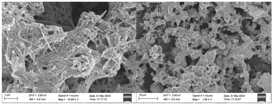
Figure 2.
Representative SEM (scanning electron microscope) image of chitosan-derived carbon dots/MoO3 nanocomposite ((A) Local enlargement of SEM image; (B) Overall morphology of the resulting nanocomposite).
As shown in Figure 2, most of the morphology was covered by nanorods or nanofibres; their size was very long, about 1 μm or so. A small amount of lamellar morphology was also observed; its size was also 1 μm or so. These morphologies should be Mo oxides. There were some nanoparticles attached to the surface of the nanofibres and nanorods; these nanoparticles should belong to the chitosan-derived carbon dots, and their size was about 20–30 nm. This is in agreement with the TEM in Figure 1. The close contact facilitated the interfacial charge transfer between the chitosan-derived carbon dots and the MoO3 nanofibres.
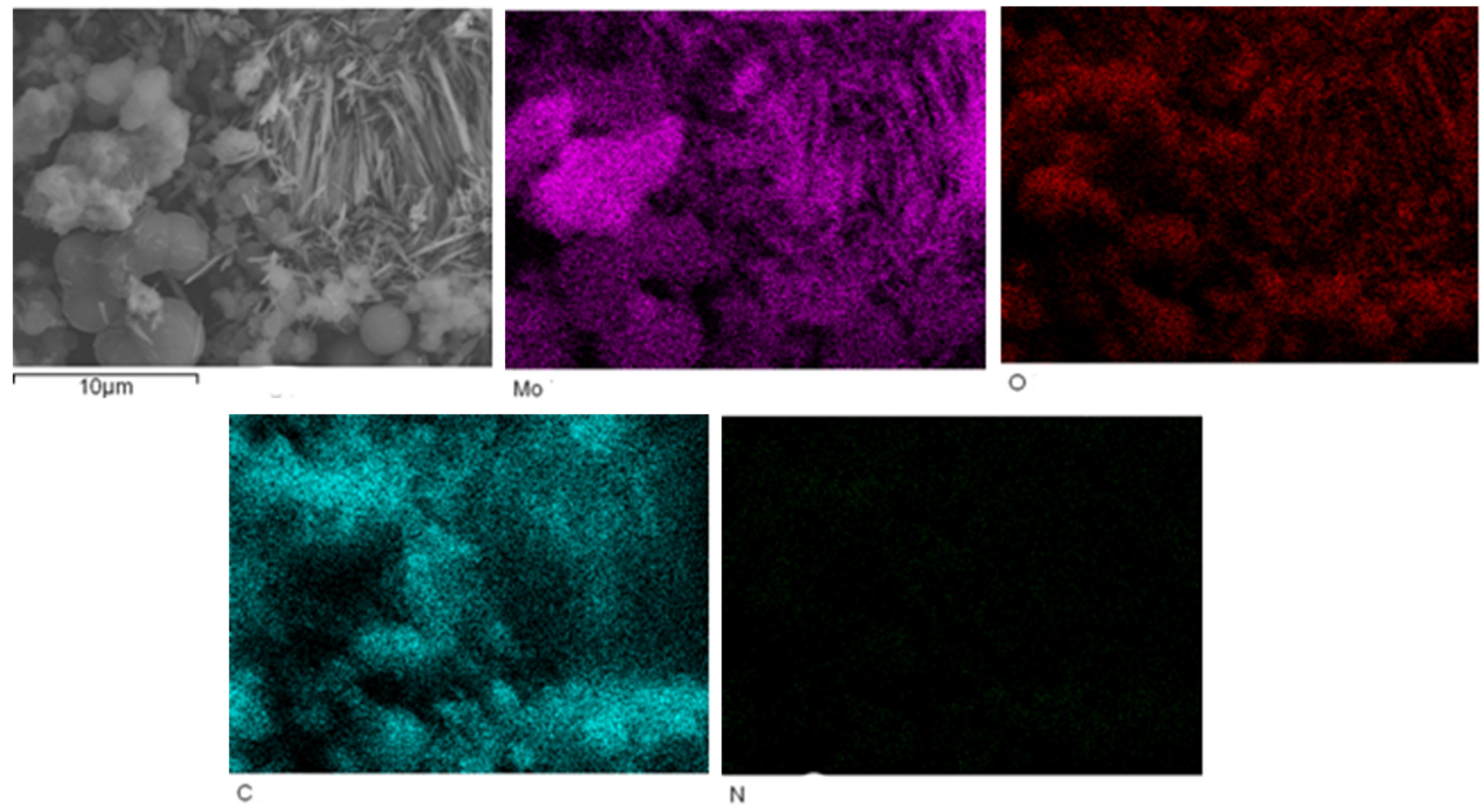
The EDS mapping of MoO3/carbon dots derived from chitosan nanocomposites is shown in Figure 3.

Figure 3.
The EDS mapping of MoO3/carbon dots derived from chitosan nanocomposites.
Figure 3 shows that the contents of Mo, O and C elements in MoO3/carbon dots derived from chitosan nanocomposites were relatively high, and the content of N element was slightly low. However, the distribution of N element was still uniform in the nanocomposite.
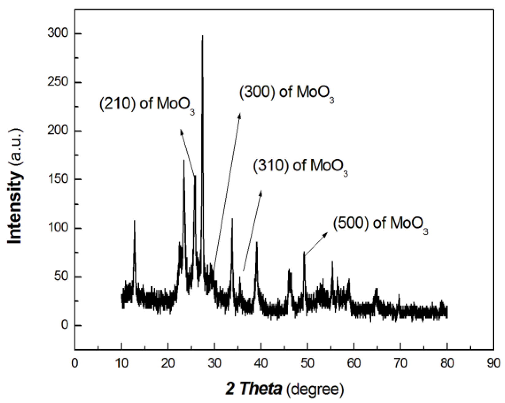
The XRD results of the chitosan-derived carbon dots/MoO3 nanocomposite are shown in Figure 4. The UV-Vis-NIR absorbance curve of chitosan-derived carbon dots/MoO3 nanocomposite is shown in Figure 5.
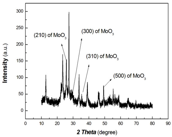
Figure 4.
The XRD results of chitosan-derived carbon dots/MoO3 nanocomposite.
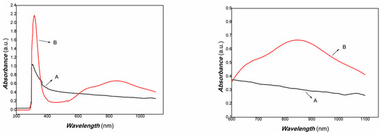
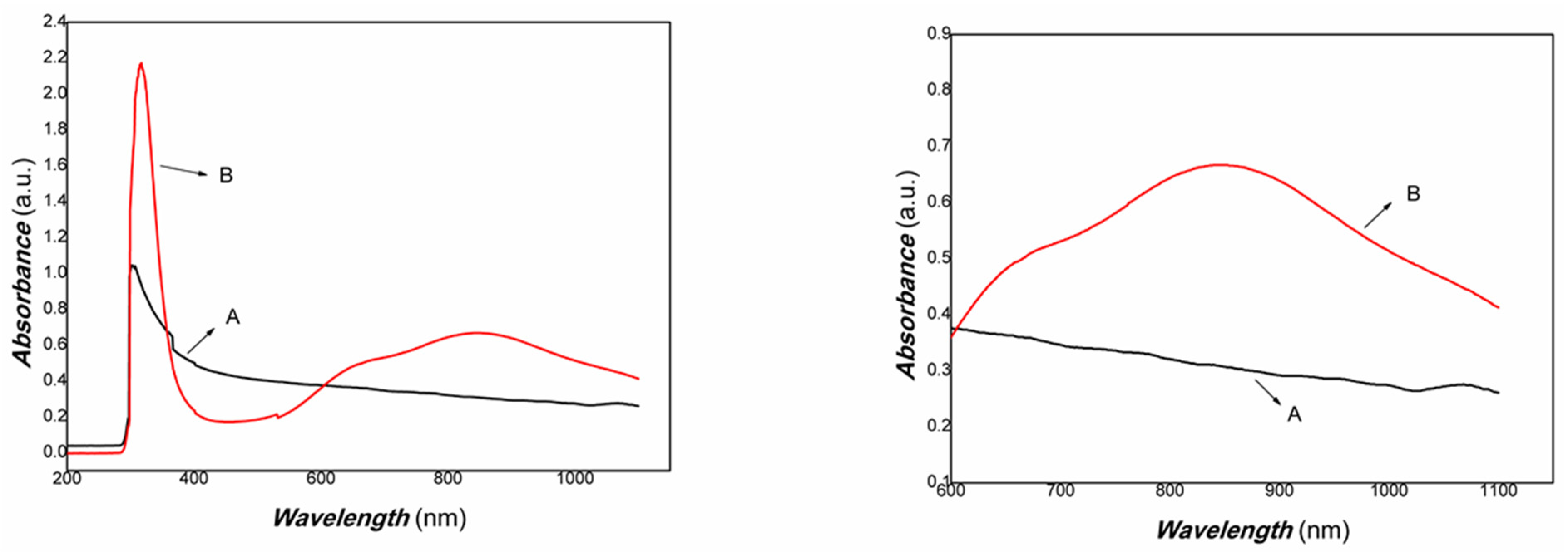
Figure 5.
The UV-Vis-NIR absorbance curve of chitosan-derived carbon dots/MoO3 nanocomposite (A: chitosan-derived carbon dots; B: chitosan-derived carbon dots/MoO3 nanocomposite).
As shown in Figure 4, the diffraction peaks at 25.6°, 29.3°, 35.47° and 49.84° are the peaks of the (210), (300), (310) and (500) planes of MoO3 (PDF# 21-0569), respectively. Meanwhile, the diffraction peaks at 20.70°, 26.23°, 42.66° and 44.90° are the (002), (100) and (101) planes of graphite of carbon nanoparticles (PDF# 41-1487). As the polymer-derived carbon nanoparticles are very complex, the diffraction peak at 20.70° may be the (111) plane of chaoite (PDF# 22-1069), which is an allotrope of carbon. Although the diffraction intensity is somewhat low, it can still be distinguished. Therefore, the resulting nanocomposite contains graphitic carbon and MoO3.
As shown in Figure 5, it was found that the chitosan-derived carbon dots/MoO3 nanocomposite exhibited a large red shift compared with chitosan-derived carbon dots and that the absorbance in the NIR region was significantly enhanced. The local enhancement is shown on the right side of Figure 5. The main reason is the electronic interaction between MoO3 and carbon dots, which activated the defect energy levels due to the presence of a large number of defects of polymer-derived carbon dots. This is advantageous for the utilisation of an NIR light source. Therefore, the transient photocurrent response to weak visible light was investigated using A4 printing paper as a substrate. The results are shown in Figure 6.
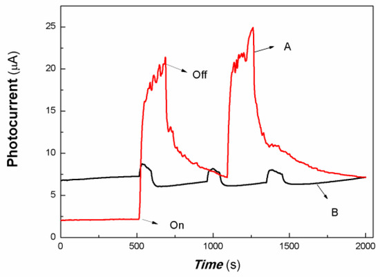
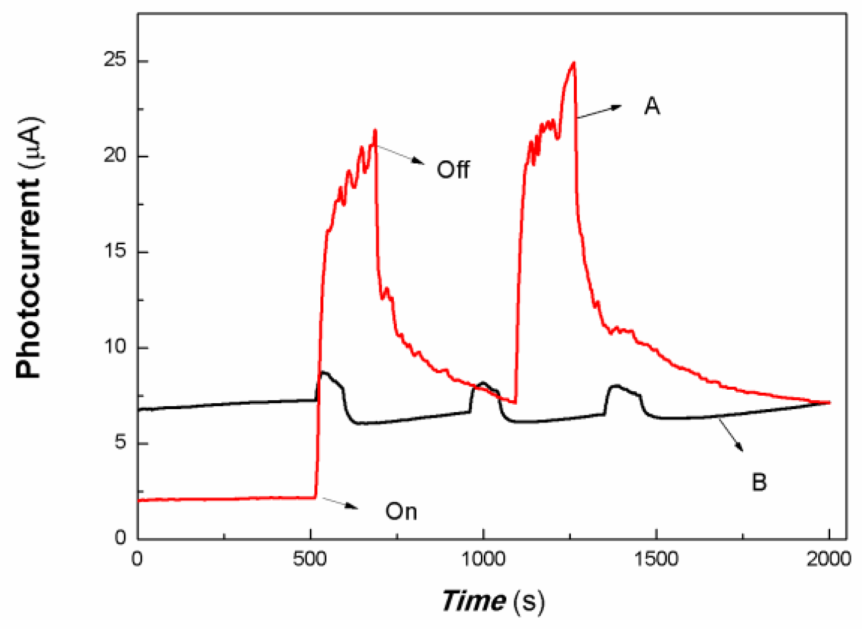
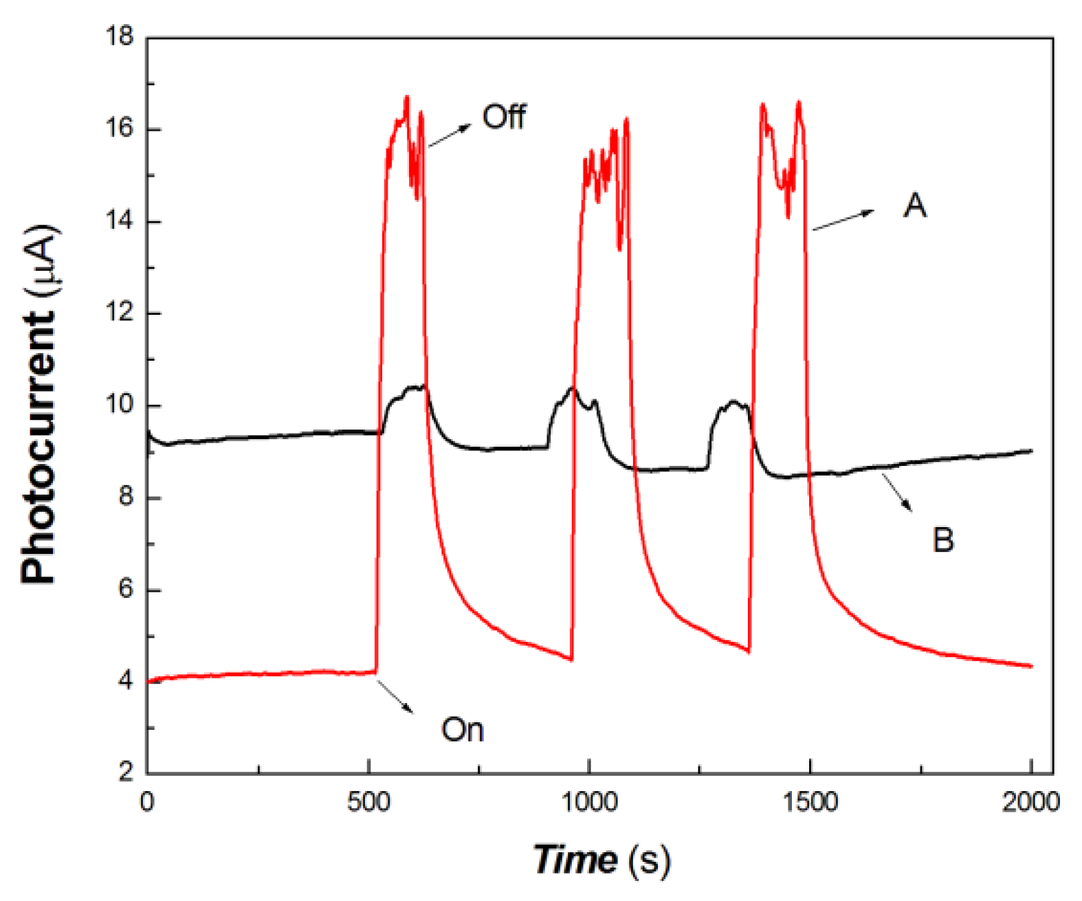
Figure 6.
The comparative transient-state photocurrent responses of a chitosan-derived carbon dots/MoO3 nanocomposite and chitosan-derived carbon dots to weak visible light (A: chitosan-derived carbon dots/MoO3 nanocomposite; B: chitosan-derived carbon dots).
The horizontal axis in Figure 6 is time (s). The vertical axis in Figure 6 is the value of the film current. As shown in Figure 6, both the chitosan-derived carbon dots/MoO3 nanocomposite and the chitosan-derived carbon dots exhibited photocurrent-switching behaviour. The response times (the time for the current to increase to about 90% of the steady-state current) were about 36.85 and 24.86 s; the recovery times (the time for the current to return to about 10% of the steady-state current) were about 212.54 and 54.84 s; and the on/off ratios were about 9.20 and 1.19 for the chitosan-derived carbon dots/MoO3 nanocomposite and chitosan-derived carbon dots. The photocurrent sensitivity of the chitosan-derived carbon dots/MoO3 nanocomposite was much higher than that of the chitosan-derived carbon dots. The on/off ratio of the chitosan-derived carbon dots/MoO3 nanocomposite was also much higher than that of the chitosan-derived carbon dots. The response time of chitosan-derived carbon dots/MoO3 nanocomposite was slightly lower than that of chitosan-derived carbon dots. The main reason for the lower response of chitosan-derived carbon dots/MoO3 nanocomposite is that the on/off ratio was much larger than that of chitosan-derived carbon dots. Under the condition of the same switching ratio, the response ratio of chitosan-derived carbon dots/MoO3 nanocomposite was much faster than that of chitosan-derived carbon dots. This indicates that strong interfacial interaction of chitosan-derived carbon dots/MoO3 was present, which promoted the interfacial charge transfer via light induction. The chitosan-derived carbon dots had a poor photoconductive response due to the presence of a large number of defects (disordered structures) and chemical groups.
In the interdisciplinary field, 532, 650, 808, 980 and 1064 nm are important light sources. In this study, 100 mW at 650 nm, 200 mW at 808 nm, 200 mW at 980 nm and 40 mW at 1064 nm were selected as typical light sources to investigate the photocurrent responses of the chitosan-derived carbon dots/MoO3 nanocomposite and chitosan-derived carbon dots. The comparative results are shown in Figure 7, Figure 8, Figure 9 and Figure 10.

Figure 7.
The comparative transient-state photocurrent responses of the chitosan-derived carbon dots/MoO3 nanocomposite and chitosan-derived carbon dots to 100 mW at 650 nm (A: chitosan-derived carbon dots/MoO3 nanocomposite; B: chitosan-derived carbon dots).
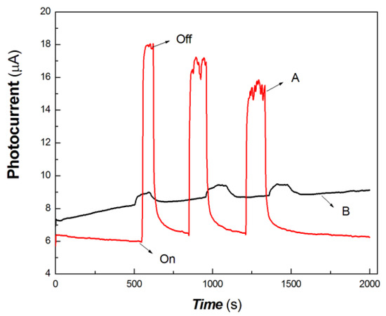
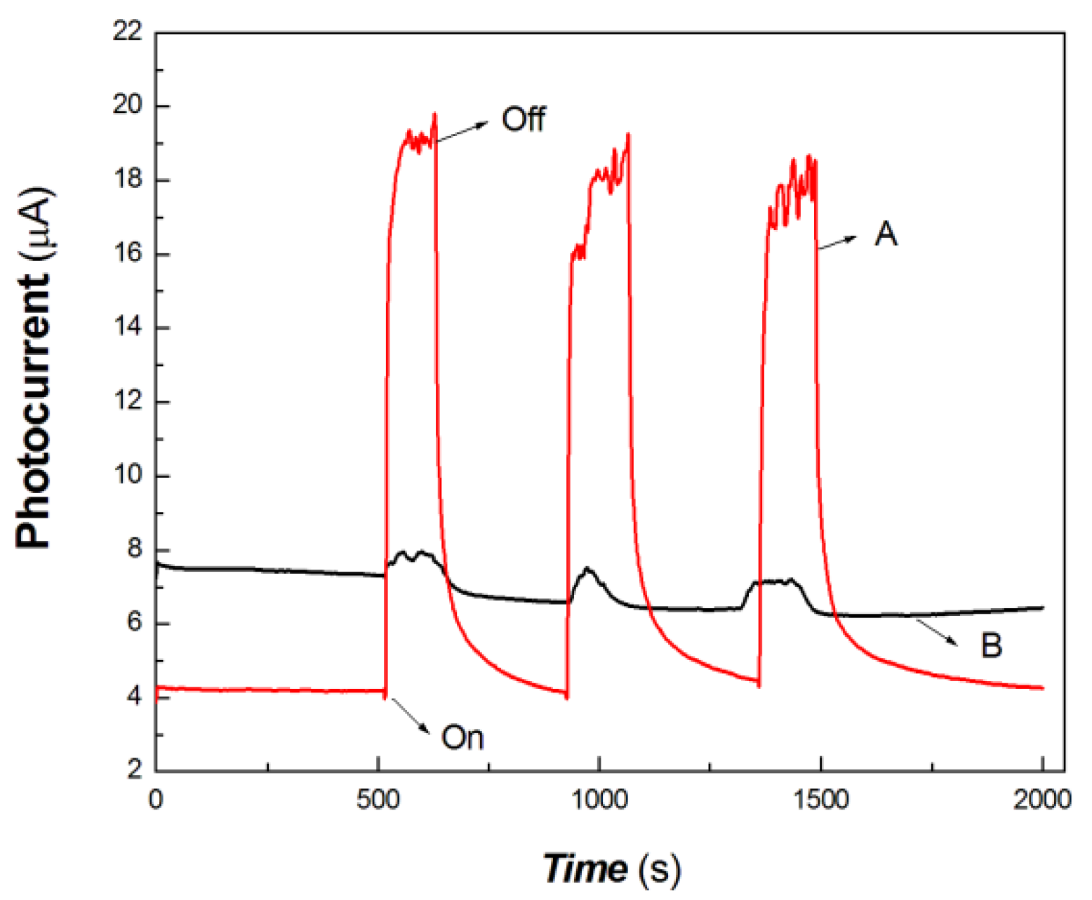
Figure 8.
The comparative transient-state photocurrent responses of the chitosan-derived carbon dots/MoO3 nanocomposite and chitosan-derived carbon dots to 200 mW at 808 nm (A: chitosan-derived carbon dots/MoO3 nanocomposite; B: chitosan-derived carbon dots).

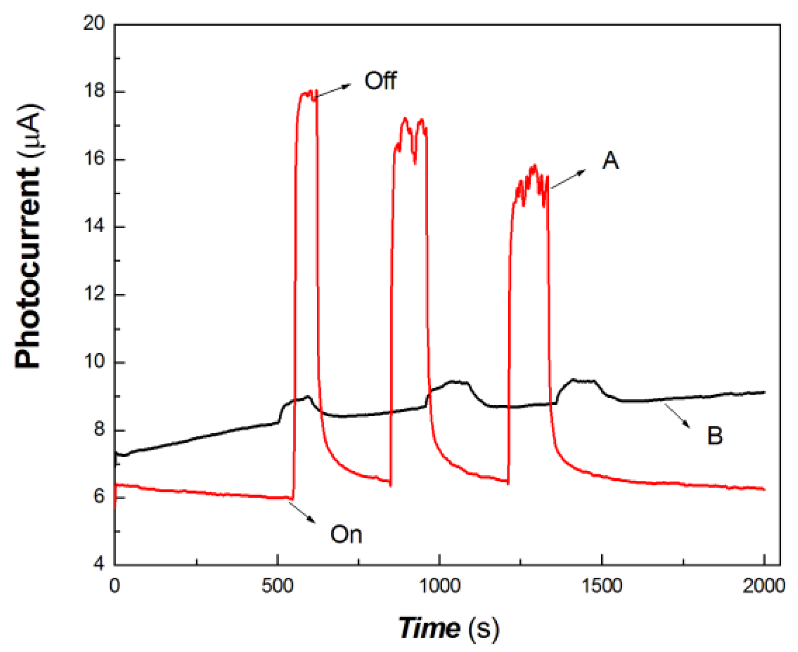
Figure 9.
The comparative transient-state photocurrent responses of the chitosan-derived carbon dots/MoO3 nanocomposite and chitosan-derived carbon dots to 200 mW at 980 nm (A: chitosan-derived carbon dots/MoO3 nanocomposite; B: chitosan-derived carbon dots).
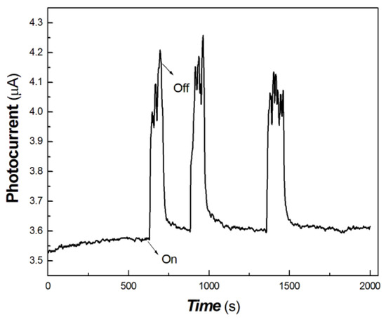
Figure 10.
The transient-state photocurrent responses of the chitosan-derived carbon dots/MoO3 nanocomposite to 40 mW at 1064 nm.
As shown in Figure 7, the chitosan-derived carbon dots/MoO3 nanocomposite showed better photocurrent response than the chitosan-derived carbon dots to 100 mW at 650 nm. The photocurrent sensitivity of chitosan-derived carbon dots/MoO3 nanocomposite was still much higher than that of chitosan-derived carbon dots. The response ratio and recovery speed were also fast. This indicates that the interfacial interaction of carbon dots/MoO3 nanocomposite enhances the extraction ability of photogenerated carriers. The chitosan-derived carbon dots had a poor photoconductive response to the light source of 100 mW at 650 nm, which is the result of the presence of a large number of defects (disordered structures) and chemical groups, which limited interfacial charge transfer.
As shown in Figure 8, the chitosan-derived carbon dots/MoO3 nanocomposite and chitosan-derived carbon dots still showed different photocurrent responses to 200 mW at 808 nm. The photocurrent sensitivity of chitosan-derived carbon dots/MoO3 nanocomposite was much higher than that of chitosan-derived carbon dots. This illustrates that the strong interfacial interaction of carbon dots/MoO3 nanocomposite improved the photocurrent extraction ability to the 808 nm light source. The chitosan-derived carbon dots had a poor photoconductive response to the light source of 200 mW at 808 nm due to the presence of a large number of defects (disordered states) and chemical groups, which limited interfacial charge transfer.
As shown in Figure 9, the chitosan-derived carbon dots/MoO3 nanocomposite and chitosan-derived carbon dots also showed different photocurrent responses to 200 mW at 980 nm. This also shows that the strong interfacial interaction of the carbon dots/MoO3 nanocomposite enhanced the photocurrent generation to the 980 nm light source. The chitosan-derived carbon dots had a poor photoconductive response to the light source 200 mW at 980 nm due to the presence of a large number of defects (disordered structures) and chemical groups, which limited interfacial charge transfer.
Comparing the results of visible light and 650, 808 and 980 nm light sources, it was found not only that the chitosan-derived dots showed poor photoconductivity but also that the baseline current showed instability, i.e., poor stability resulted from the presence of defects and some chemical groups. The imbalance of charge trapping and de-trapping led to the instability of the baseline current and some difficulty in extracting the photogenerated carriers. This shows that the chitosan-derived carbon dots/MoO3 nanocomposite had much better photocurrent extraction ability than the chitosan-derived carbon dots. The enhanced, excellent property contributed to the strong interfacial interaction between the chitosan-derived carbon dots and MoO3, promoted interfacial charge transfer and enhanced the extraction ability of photogenerated carriers due to the reduction of electronic traps.
As shown in Figure 10, the chitosan-derived carbon dots/MoO3 nanocomposite still showed good photocurrent response to the light source of 40 mW at 1064 nm. However, for the chitosan-derived carbon dots, it is difficult to obtain the photocurrent curves upon excitation at 1064 nm for the structures without MoO3 under similar experimental conditions. This shows that the resulting nanojunction had a good photocurrent response to the weak 1064 nm NIR light source, which has a potential application in biomedical or other fields, since 1064 nm is an important light source in the NIR-Ⅱ region.
In short, as shown by the above research results, the chitosan-derived carbon dots/MoO3 nanocomposite exhibited good photocurrent responses by changing the excitation wavelength in a wide light wavelength range. For easy, intuitive comparison, the effects of interfacial interaction between MoO3 and chitosan-derived carbon dots on photocurrent responses, response time, recovery time and on/off ratio are summarised in Table 1.

Table 1.
The effects of the interface interaction between MoO3 and carbon dots derived from chitosan on the photocurrent responses.
Since MoO3 belongs to the wide-bandgap semiconductor materials, some impurities or defects have to be introduced into the nanocomposite. Here, the photocurrent behaviour was investigated by varying the excitation power of some typical light sources. The results are shown in Figure 11, Figure 12 and Figure 13.
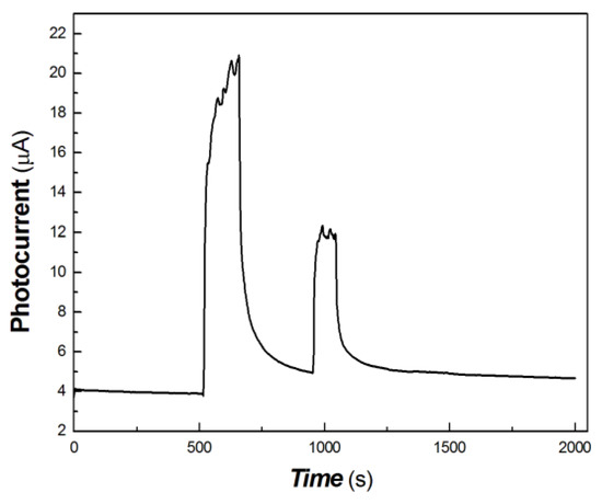
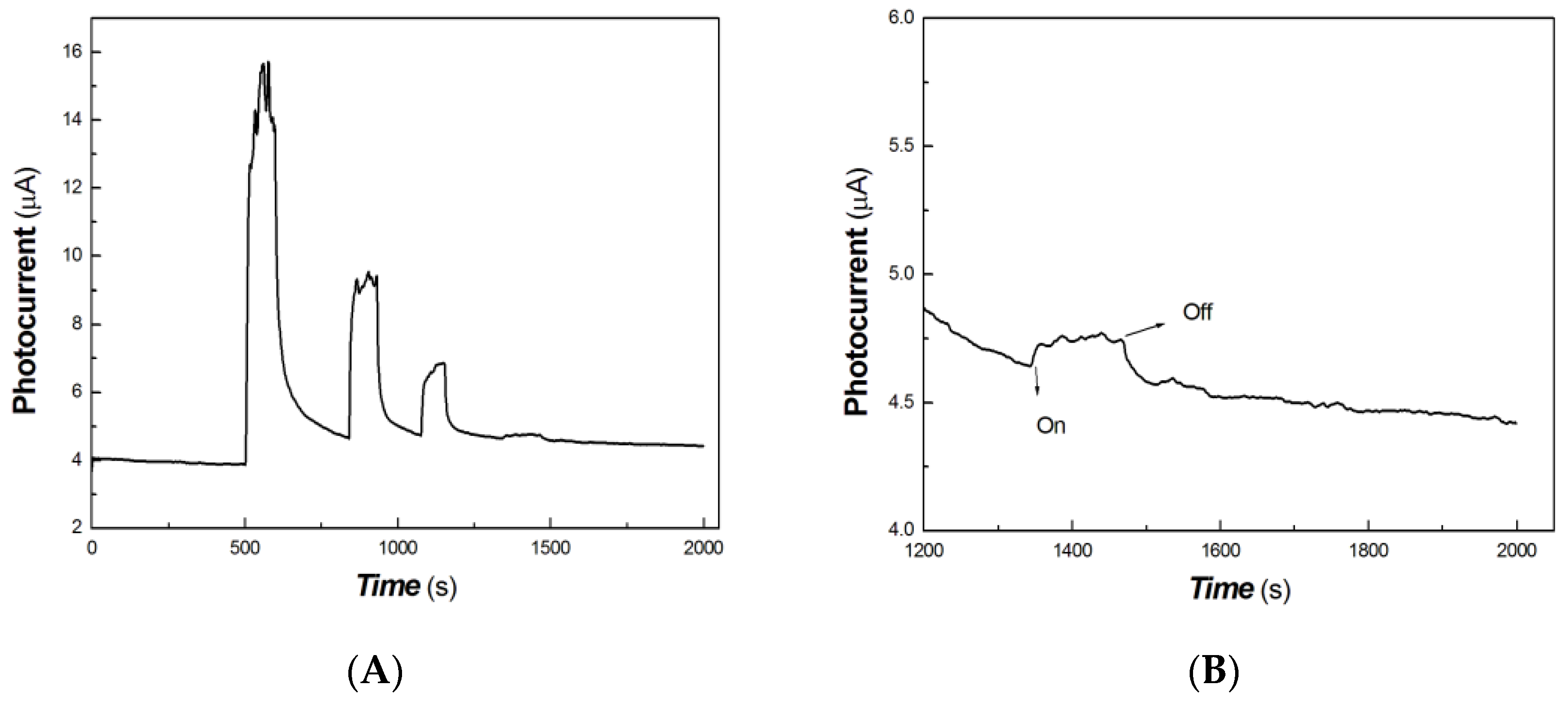
Figure 11.
The transient-state photocurrent responses of the chitosan-derived carbon dots/MoO3 nanocomposite to the light sources of 100, 50 and 5 mW at 650 nm.
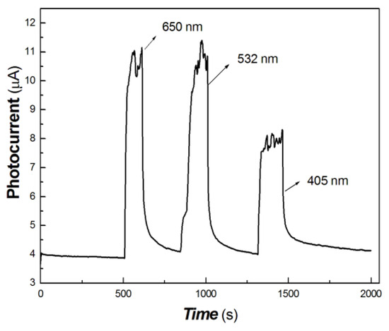
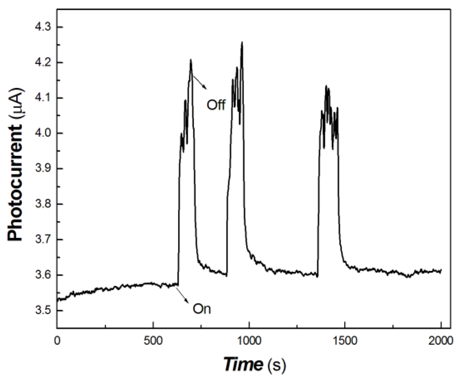
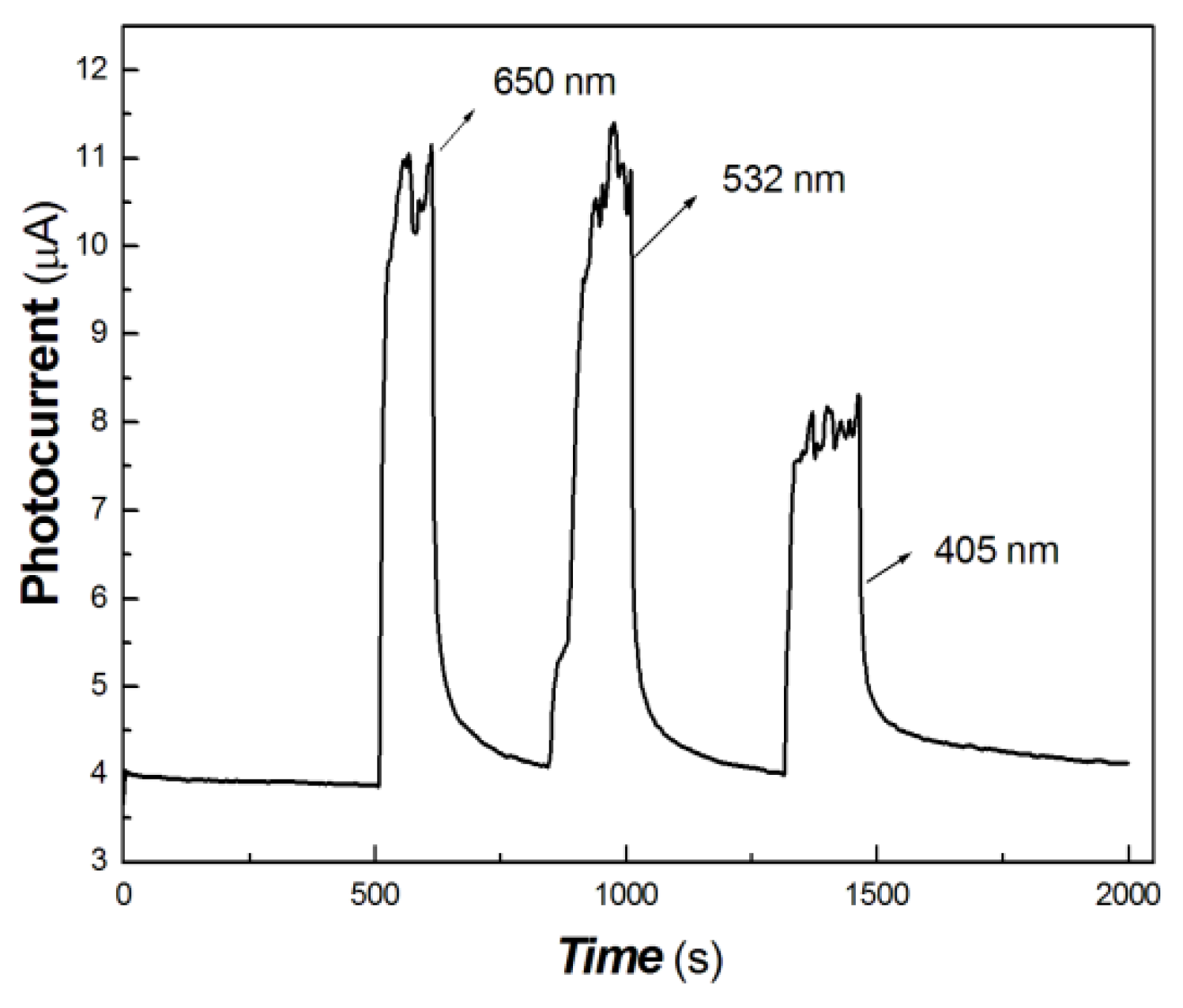
Figure 12.
The transient-state photocurrent responses of the chitosan-derived carbon dots/MoO3 nanocomposite to the light source of 50 mW at 650, 532 and 405 nm.
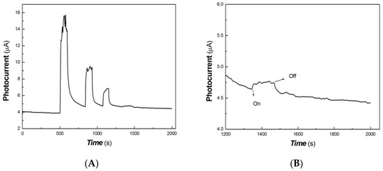
Figure 13.
The transient-state photocurrent responses of the chitosan-derived carbon dots/MoO3 nanocomposite to the light sources of 200, 100, 50 and 5 mW at 980 nm ((A) 200, 100, 50 and 5 mW at 980 nm; (B) partially enlarged response to 5 mW at 980 nm).
As shown in Figure 11, it was found that the polymer-derived carbon dots/MoO3 nanocomposite still had good measurable photocurrent signal in response to the light source of 50 mW at 650 nm. However, it was difficult to obtain the photocurrent signal in response to the light source of 5 mW at 650 nm. This illustrates that the photogenerated carriers were completely trapped by the defects under 5 mW 650 nm light source excitation, and the photocurrent was difficult to measure.
Figure 12 shows that the on/off ratio of the 650 and 532 nm light sources (50 mW) are basically equivalent and much higher than that of the 405 nm light source (50 mW). This shows that the photocurrent response to the 650 and 532 nm light sources is better than that to the 405 nm light source.
Similarly, as shown in Figure 13, it was still possible to measure the photocurrent signal to the 5 mW 980 nm light source. The partially magnified image of the light source of 5 mW at 980 nm is shown in Figure 13B. This illustrates that the response of the chitosan-derived carbon dots/MoO3 nanocomposite to the 980 nm NIR was more photocurrent-sensitive than that to other wavelength light sources. In addition, MoO3 is a wide-bandgap material, and its bandgap width is about 2.8–3.6 eV. The incorporation of MoO3 into polymer-derived carbon dots improved optical absorption and photocurrent in the NIR region. This was mainly due to the strong interfacial interaction and led to the production of oxygen vacancies in MoO3−x. MoO3−x has good plasmonic properties, which further promoted the interfacial charge transfer. Moreover, the introduction of the impurity level or defect level in the nanocomposite also produced a large red shift, which showed a good photocurrent response in the NIR.
It is well known that MoO3 is a wide-bandgap semiconductor. Light at more than 400 nm is difficult to be absorbed. Therefore, the MoO3/chitosan-derived carbon dots which exhibiting excellent photocurrent signals in a wide light spectral range is mainly due to the contribution of chitosan-derived carbon dots. A large number of amino groups were presented in the chitosan molecule, resulting in abundant N element in the chitosan-derived carbon dots. The lone electron pair of N element was involved in the electron delocalisation of chitosan-derived carbon dots. The introduction of the impurity level or defect level also resulted in the chitosan-derived carbon dots showing good absorbance in a broad light spectral range. The strong interfacial interaction of MoO3/chitosan-derived carbon dots promoted interfacial charge transfer. The schematic band gap of MoO3/chitosan-derived carbon dots is shown in Figure 14.
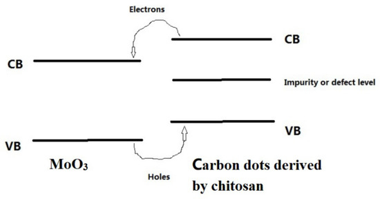
Figure 14.
The schematic band gap diagram of MoO3/carbon dots derived from chitosan.
As shown in Figure 14, it can be found that under the irradiation of a long-wavelength light source, the electrons of the VB (valence band) of carbon dots derived from chitosan were excited to the CB (conduction band) of carbon dots; then, the electrons of the CB (conduction band) of carbon dots were transferred to the CB (conduction band) of MoO3. The holes of the VB (valence band) of MoO3 were transferred to the VB (valence band) of the carbon dots. The application of a DC bias resulted in the generation of a photocurrent. The introduction of the impurity level or defect level played an important role in the absorption in a broad light spectral range of the chitosan-derived carbon dots.
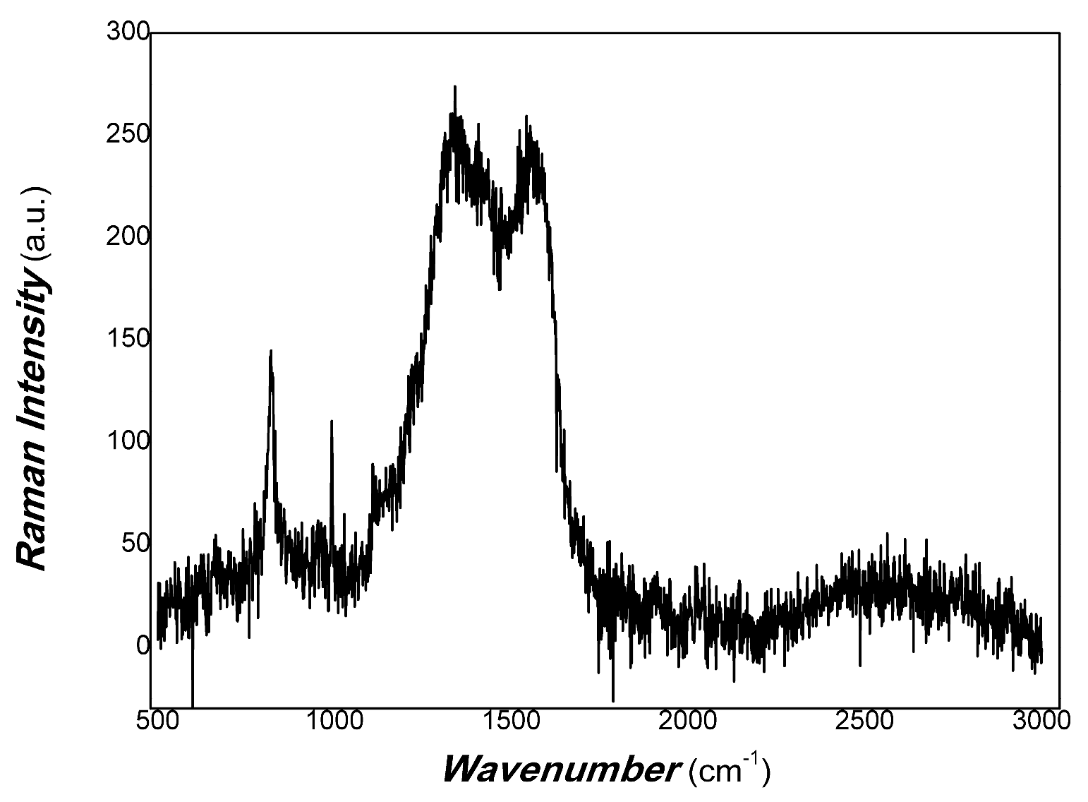
The carbon defect of MoO3/carbon dots derived from chitosan was characterised by Raman spectra. The results are shown in Figure 15.
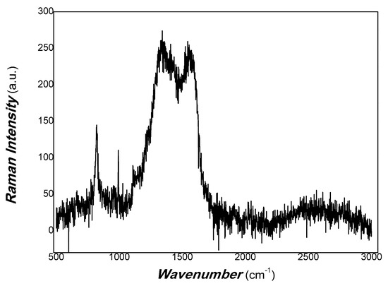
Figure 15.
The Raman spectra of MoO3/carbon dots derived from chitosan.
As shown in Figure 15, the broadband around 1350 cm−1 was found to correspond to the D band of disorder in carbon nanostructures. The D peak around 1350 cm−1 corresponds to the A1g symmetry breathing mode involving phonons near the K-zone boundary, which is forbidden in perfect graphite and only becomes active in the presence of disordered structures. The broadening band of the D peak is correlated with a distribution of clusters of different orders, disorder and dimensions, depending on the disorder of the carbon nanoparticle. The wave number at about 1580 cm-1 also showed a broadband belonging to the G band of the carbon sp2 cluster hybrid. Its sp2 cluster included wrinkled ring-like configurations consisting of five-, six-, seven- and eight-fold disordered rings; olefinic sp2 chains; sp2 dimers embedded in the sp3 matrix; bond angle disorder at sp2 sites; etc. [79]. The complexity is due to the polymer-derived carbon dots. The complex structure of polymer-derived carbon dots is mainly due to the structural complexity of the precursors used (structure of polymer materials), i.e., primary structure, secondary structure and their aggregation state structure. In the process of polymer condensation, sp2 and sp3 hybrid polymer carbon dots are formed, depending on the synthesis conditions. The combination of disordered and ordered structures shows diversity. The ordered structure includes short-range order, medium-range order and long-range order. Disordered structures are also involved in bond angle disorder, bond length disorder and hybrid structures. Ordered sp2 structures contribute to charge transfer in carbon nanomaterials, and disordered sp2 and sp3 structures contribute to non-radiative energy consumption. sp2 structures are composed of five-, six-, seven- and eight-fold rings; olefinic sp2 chains; sp2 dimers; aromatic oligomers; and clusters. Unlike the sp2 structure of pure graphitic carbon, the ordered structures of the polymer-derived carbon dots contained disordered structures, and the disordered structures included some short-range ordered structures. However, since the physical mechanism of inorganic–organic hybrids is very complex [80], it is still a great challenge to study the photophysical mechanism and carrier transfer of polymer-derived carbon nanomaterials using photo-triggering. Controlling the interfaces of nanocomposites can expand many interdisciplinary applications. Recently, Zeng and co-workers [81] obtained bright and stable deep red light-emitting property by using the switchable interfacial reaction as a good example. Figure 14 also shows that the intensity of the D band was slightly higher than that of G. This illustrates that the disorder of chitosan-derived carbon dots was excellent, which required defect mitigation for physical signal measurement.
4. Conclusions
In conclusion, chitosan-derived carbon dots were obtained through the carbonisation of cross-linked chitosan, which exhibited some absorption in the NIR region due to the N-doping of carbon nanomaterials. A strong interfacial interaction between the chitosan-derived carbon dots and MoO3 nanosheets enhanced the acquisition of the photoelectric signal in a wide light excitation range. The resulting nanocomposite coating on an A4 printing paper substrate showed broadband spectrum photocurrent signals, and the effects of excitation light wavelengths and incident light power on the switching ratio (on/off) were significant. This illustrates that the resulting nanocomposite could have potential applications in broadband flexible photosensors or in interdisciplinary fields. The physical mechanism was discussed based on the combination of ordered and disordered structures of polymer-derived carbon nanomaterials. This study provided a low-cost and environmentally friendly approach to the synthesis of nanocomposites and the passivation of defects of carbon nanomaterials, which, here, exhibited good photocurrent signals in a wide range of the light spectrum due to the enhancement in interfacial charge transfer between the chitosan-derived carbon dots and MoO3 nanosheets. This is helpful to study the photodynamic process and its mechanism of light–matter interaction. It also helps to expand interdisciplinary applications through interfacial regulation.
Author Contributions
Conceptualization, methodology, investigation, writing—original draft preparation, writing—review and editing, funding acquisition, X.M.; investigation, X.Z., investigation, M.G. and Y.W.; resources, G.L.; all authors analysed the data; all authors discussed the results of the paper. All authors have read and agreed to the published version of the manuscript.
Funding
This project was supported by the Natural Science Foundation of Shandong Province (project No. ZR2013EMM008).
Institutional Review Board Statement
This study did not involve ethical issues.
Informed Consent Statement
This study did not involve humans.
Data Availability Statement
The data presented in this study are available upon request from the corresponding author. The data are not publicly available due to privacy.
Acknowledgments
The authors thank You Wang and Guang Li of Zhejiang University for the fabrication of several electrodes and for checking the English of the paper. TEM was performed by Chunsheng Wang, and SEM, by Fang Tian. Raman spectra were obtained by Weiwei Wang at the Structural Composition Testing Center, School of Chemistry and Chemical Engineering, Shandong University. EDS mapping was performed by Wenhai Wang, Yantai Institute of Coastal Zone Research, Chinese Academy of Sciences. Some students, such as Zhishun Chen, Guozheng Wei, Zuopeng Wang, Hao Liu, et al., performed part of the experiments.
Conflicts of Interest
The authors declare no conflicts of interest.
References
- Yue, X.; Zhang, J.; Chen, D.; Xu, X.; Wu, H.; Zhou, Y.; Liang, Z. Multifunctional α-MoO3 Nanobelt Interlayer with the Capacity Compensation Effect for High-Energy Lithium-Sulfur Batteries. ACS Appl. Mater. Interfaces 2023, 15, 13064–13072. [Google Scholar] [CrossRef]
- Wei, K.; Qiu, J.; Zhao, Y.; Ma, S.; Wei, Y.; Li, H.; Zeng, C.; Cui, Y. Tunable oxygen vacancies in MoO3 lattice with improved electrochemical performance for Li-ion battery thin film cathode. Ceram. Int. 2023, 49, 21729–21736. [Google Scholar] [CrossRef]
- Wu, Y.; Liu, W.; Zhang, Z.; Zheng, Y.; Fu, X.; Lu, J.; Cheng, S.; Su, J.; Gao, Y. Defect-Rich MoO3 Nanobelts for ultrafast and wide-temperature proton battery. Energy Storage Mater. 2023, 61, 102849. [Google Scholar] [CrossRef]
- Qin, J.; Sun, B.; Mao, S.; Yang, Y.; Liu, M.; Rao, Z.; Ke, C.; Zhao, Y. Improved resistive switching performance and mechanism analysis of MoO3 nanorods based memristors. Mater. Today Commun. 2023, 36, 106770. [Google Scholar] [CrossRef]
- Shin, S.; Kima, S.; Song, H.; Kim, H.; Kim, T.; Du, H.; Kang, D.; Hwang, J.Y.; Woo, Y.S.; Seo, S. Highly stable self-passivated MoO3-doped graphene film with nonvolatile MoOx layer. Mater. Today Commun. 2022, 33, 104432. [Google Scholar] [CrossRef]
- Rani, V.; Malhotra, M.; Patial, S.; Sharma, S.; Singh, P.; Khan, A.A.P.; Thakur, S.; Raizada, P.; Ahamad, T.; Asiri, A.M. Formulation strategies for the photocatalytic H2 evolution and photodegradation using MoO3-based Z-scheme photocatalysts. Mater. Chem. Phys. 2023, 299, 127454. [Google Scholar] [CrossRef]
- Li, J.; Ma, L.; Huang, Y.; Luo, B.; Jing, D. In situ construction of oxygen-deficient MoO3−x nanosheets/porous graphitic carbon nitride for enhanced photothermal-photocatalytic hydrogen evolution. Int. J. Hydrog. Energy 2023, 48, 13170–13180. [Google Scholar] [CrossRef]
- Augustine, S.; Kumar, P.; Malhotra, B.D. Amine-Functionalized MoO3@RGO Nanohybrid-Based Biosensor for Breast Cancer Detection. ACS Appl. Bio Mater. 2019, 2, 5366–5378. [Google Scholar] [CrossRef] [PubMed]
- Kumar, A.; Chauhan, P. Hierarchical nanodisk synthesis of α-MoO3 nanomaterials for highly selective and sensitive ethanol vapour detection. Mater. Lett. 2023, 330, 133375. [Google Scholar] [CrossRef]
- Mobtakeri, S.; Habashyani, S.; Gür, E. Highly Responsive Pd-Decorated MoO3 Nanowall H2 Gas Sensors Obtained from In-Situ-Controlled Thermal Oxidation of Sputtered MoS2 Films. ACS Appl. Mater. Interfaces 2022, 14, 25741–25752. [Google Scholar] [CrossRef]
- Liu, S.; Yang, Z.; Zhao, L.; Zhang, Y.; Xing, Y.; Fei, T.; Zhang, H.; Zhang, T. Glucose-assisted combustion synthesis of oxygen vacancy enriched α-MoO3 for ethanol sensing. J. Alloys Compd. 2022, 902, 163711. [Google Scholar] [CrossRef]
- Ankinapalli, O.R.; Krishna, B.N.V.; Yu, J.S. synthesized MoV2O8/MoO3 microclusters-based electrode materials for high-capacity asymmetric supercapacitors. J. Alloys Compd. 2023, 948, 169770. [Google Scholar] [CrossRef]
- Sui, Y.; Ma, Y.; Gao, Y.; Song, J.; Ye, Y.; Niu, H.; Ma, W.; Zhang, P.; Qin, C. PANI/MoO3−x shell–core composites with enhanced rate and cycling performance for flexible solid-state supercapacitors and electrochromic applications. New J. Chem. 2021, 45, 10654–10663. [Google Scholar] [CrossRef]
- Dong, W.; Lv, Y.; Xiao, L.; Fan, Y.; Zhang, N.; Liu, X. Bifunctional MoO3-WO3/Ag/MoO3-WO3 Films for Efficient ITO-Free Electrochromic Devices. ACS Appl. Mater. Interfaces 2016, 8, 33842–33847. [Google Scholar] [CrossRef]
- Li, H.; Wang, L.; Du, F. Controllable synthesis and formation mechanism of pure and Fe-doped h-MoO3 microrods under hydrothermal reaction conditions. CrystEngComm 2023, 25, 4089–4099. [Google Scholar] [CrossRef]
- Zhao, X.; Chu, Q.; Guo, S.; Park, E.; Jin, S.; Chen, L.; Liu, Y.; Jung, Y.M. Controllable hot electron transfer in the Ag/MoO3 layer by layer system: Thickness-dependent MoO3 layer. Spectrochim. Acta Part A Mol. Biomol. Spectrosc. 2023, 286, 121995. [Google Scholar] [CrossRef]
- Xian, H.; Guo, H.; Xia, J.; Chen, Q.; Luo, Y.; Song, R.; Li, T.; Traversa, E. Iron-Doped MoO3 Nanosheets for Boosting Nitrogen Fixation to Ammonia at Ambient Conditions. ACS Appl. Mater. Interfaces 2021, 13, 7142–7151. [Google Scholar] [CrossRef] [PubMed]
- Xiong, R.; Ke, X.; Jia, W.; Xiao, Y.; Cheng, B.; Lei, S. Photothermal-coupled solar photocatalytic CO2 reduction with high efficiency and selectivity on a MoO3-x@ZnIn2S4 core-shell S-scheme heterojunction. J. Mater. Chem. A 2023, 11, 2178–2190. [Google Scholar] [CrossRef]
- Alnaggar, G.; Alkanad, K.; Chandrashekar, S.S.G.; Bajiri, M.A.; Drmosh, Q.A.; Krishnappagowda, L.N.; Ananda, S. Rational design of a 2D TiO2–MoO3 step-scheme heterostructure for boosted photocatalytic overall water splitting. New J. Chem. 2022, 46, 9629–9640. [Google Scholar] [CrossRef]
- Dereshgi, S.A.; Larciprete, M.C.A.; Centini, M.; Murthy, A.A.; Tang, K.; Wu, J.; Dravid, V.P.; Aydin, K. Tuning of Optical Phonons in α-MoO3-VO2 Multilayers. ACS Appl. Mater. Interfaces 2021, 13, 48981–48987. [Google Scholar] [CrossRef]
- Xu, K.; Duan, S.; Tang, Q.; Zhu, Q.; Zhao, W.; Yu, X.; Yang, Y.; Yu, T.; Yuan, C. P-N heterointerface-determined acetone sensing characteristics of α-MoO3@NiO core@shell nanobelts. CrystEngComm 2019, 21, 5834–5844. [Google Scholar] [CrossRef]
- Li, K.; Wu, W.; Jiang, Y.; Wang, Z.; Liu, X.; Li, J.; Xia, D.; Xu, X.; Fan, J.; Lin, K. Highly enhanced H2 evolution of MoO3/g-C3N4 hybrid composites based on a direct Z-scheme photocatalytic system. Inorg. Chem. Front. 2021, 8, 1154–1165. [Google Scholar] [CrossRef]
- Song, T.; Xie, C.; Che, Q.; Yang, P. Enhanced carrier separation in g-C3N4/MoO3-x heterostructures towards efficient phenol removal. J. Ind. Eng. Chem. 2023, 122, 415–425. [Google Scholar] [CrossRef]
- Patnaik, S.; Swain, G.; Parida, K.M. Highly efficient charge transfer through a double Z-scheme mechanism by a Cu-promoted MoO3/g-C3N4 hybrid nanocomposite with superior electrochemical and photocatalytic performance. Nanoscale 2018, 10, 5950–5964. [Google Scholar] [CrossRef]
- Wang, L.; Ji, X.; Wang, T.; Zhang, Q. Novel Red Emission from MoO3/MoS2–MoO2–MoO3 Core-Shell Belt Surface. ACS Appl. Mater. Interfaces 2018, 10, 36297–36303. [Google Scholar] [CrossRef] [PubMed]
- Agarwal, V.; Metiu, H. Oxygen Vacancy Formation on α-MoO3 Slabs and Ribbons. J. Phys. Chem. C 2016, 120, 19252–19264. [Google Scholar] [CrossRef]
- Inzani, K.; Grande, T.; Vullum-Bruer, F.; Selbach, S.M. A van der Waals Density Functional Study of MoO3 and Its Oxygen Vacancies. J. Phys. Chem. C 2016, 120, 8959–8968. [Google Scholar] [CrossRef]
- Hu, Y.; Liu, X.; Xu, S.; Wei, W.; Zeng, G.; Yuan, H.; Gao, Q.; Guo, J.; Chao, M.; Liang, E. Improving the Thermal Expansion and Capacitance Properties of MoO3 by Introducing Oxygen Vacancies. J. Phys. Chem. C 2021, 125, 10817–10823. [Google Scholar] [CrossRef]
- Head, A.R.; Tsyshevsky, R.; Trotochaud, L.; Yu, Y.; Kyhl, L.; Karslıoǧlu, O.; Kuklja, M.M.; Bluhm, H. Adsorption of Dimethyl Methylphosphonate on MoO3: The Role of Oxygen Vacancies. J. Phys. Chem. C 2016, 120, 29077–29088. [Google Scholar] [CrossRef]
- Shahrokhi, M.; Raybaud, P.; Bahers, T.L. 2D MoO3-xSx/MoS2 van der Waals Assembly: A Tunable Heterojunction with Attractive Properties for Photocatalysis. ACS Appl. Mater. Interfaces 2021, 13, 36465–36474. [Google Scholar] [CrossRef]
- Duraisamy, S.; Ganguly, A.; Sharma, P.K.; Benson, J.; Davis, J.; Papakonstantinou, P. One-Step Hydrothermal Synthesis of Phase-Engineered MoS2/MoO3 Electrocatalysts for Hydrogen Evolution Reaction. ACS Appl. Nano Mater. 2021, 4, 2642–2656. [Google Scholar] [CrossRef]
- Wang, M.; Koski, K.J. Reversible Chemochromic MoO3 Nanoribbons through Zerovalent Metal Intercalation. ACS Nano 2015, 9, 3226–3233. [Google Scholar] [CrossRef] [PubMed]
- Ohisa, S.; Kagami, S.; Pu, Y.; Chiba, T.; Kido, J. A Solution-Processed Heteropoly Acid Containing MoO3 Units as a Hole-Injection Material for Highly Stable Organic Light-Emitting Devices. ACS Appl. Mater. Interfaces 2016, 8, 20946–20954. [Google Scholar] [CrossRef] [PubMed]
- Brown, P.K.R.; Lunt, R.R.; Zhao, N.; Osedach, T.P.; Wanger, D.D.; Chang, L.; Bawendi, M.G.; Bulović, V. Improved Current Extraction from ZnO/PbS Quantum Dot Heterojunction Photovoltaics Using a MoO3 Interfacial Layer. Nano Lett. 2011, 11, 2955–2961. [Google Scholar] [CrossRef] [PubMed]
- Kumari, J.; Bhardwaj, J.S.; Rahul; Agarwal, P. Oxygen Plasma Treatment of Thermally Evaporated MoO3-x Films: An Approach to Tune the Work Function. ACS Appl. Electron. Mater. 2023; in press. [Google Scholar]
- Peelaers, H.; Chabinyc, M.L.; Van de Walle, C.G. Controlling n-Type Doping in MoO3. Chem. Mater. 2017, 29, 2563–2567. [Google Scholar] [CrossRef]
- Zhang, W.; Qu, Q.; Lai, K. High-Mobility Transport Anisotropy in Few-Layer MoO3 and Its Origin. ACS Appl. Mater. Interfaces 2017, 9, 1702–1709. [Google Scholar] [CrossRef] [PubMed]
- Liao, X.; Habisreutinger, S.N.; Wiesner, S.; Sadoughi, G.; Abou-Ras, D.; Gluba, M.A.; Wilks, R.G.; Félix, R.; Rusu, M.; Nicholas, R.J.; et al. Chemical Interaction at the MoO3/CH3NH3PbI3-xClx Interface. ACS Appl. Mater. Interfaces 2021, 13, 17085–17092. [Google Scholar] [CrossRef]
- Yang, Z.; Guo, C.; Qin, L.; Hu, J.; Luan, P.; Liang, Z.; Li, X.; Ding, H.; Wang, D.; Zhang, T.; et al. Enhanced Organic Thin-Film Transistor Stability by Preventing MoO3 Diffusion with Metal/MoO3/Organic Multilayered Interface Source-Drain Contact. ACS Appl. Mater. Interfaces 2023, 15, 1704–1717. [Google Scholar] [CrossRef]
- Andron, I.; Marichez, L.; Jubera, V.; Labrugère, C.; Duttine, M.; Frayret, C.; Gaudon, M. Photochromic Behavior of ZnO/MoO3 Interfaces. ACS Appl. Mater. Interfaces 2020, 12, 46972–46980. [Google Scholar] [CrossRef]
- Qin, P.; Fang, G.; Cheng, F.; Ke, W.; Lei, H.; Wang, H.; Zhao, X. Sulfur-Doped Molybdenum Oxide Anode Interface Layer for Organic Solar Cell Application. ACS Appl. Mater. Interfaces 2014, 6, 2963–2973. [Google Scholar] [CrossRef]
- Liu, H.; Lee, C.J.J.; Guo, S.; Chi, D. New Insights into Planar Defects in Layered α-MoO3 Crystals. Langmuir 2018, 34, 14003–14011. [Google Scholar] [CrossRef]
- Hu, B.; Mai, L.; Chen, W.; Yang, F. From MoO3 Nanobelts to MoO2 Nanorods: Structure Transformation and Electrical Transport. ACS Nano 2009, 3, 478–482. [Google Scholar] [CrossRef]
- Yin, Y.; Lewis, D.A.; Andersson, G.G. Influence of Moisture on the Energy-Level Alignment at the MoO3/Organic Interfaces. ACS Appl. Mater. Interfaces 2018, 10, 44163–44172. [Google Scholar] [CrossRef]
- Kumar, V.; Sumboja, A.; Wang, J.; Bhavanasi, V.; Nguyen, V.C.; Lee, P.S. Topotactic Phase Transformation of Hexagonal MoO3 to Layered MoO3-II and Its Two-Dimensional (2D) Nanosheets. Chem. Mater. 2014, 26, 5533–5539. [Google Scholar] [CrossRef]
- Apergi, S.; Koch, C.; Brocks, G.; Olthof, S.; Tao, S. Decomposition of Organic Perovskite Precursors on MoO3: Role of Halogen and Surface Defects. ACS Appl. Mater. Interfaces 2022, 14, 34208–34219. [Google Scholar] [CrossRef]
- Roy, D.; Das, B.K.; Riaz, S.N.; Das, D.; Sarkar, S.; Chattopadhyay, K.K. Oxygen Vacancy-Induced Band Engineering and Metal Unsaturation in MoS2-MoO3 with Spillover-Based Confined Catalysis. ACS Appl. Energy Mater. 2023, 6, 4892–4908. [Google Scholar] [CrossRef]
- Reidy, K.; Mortelmans, W.; Jo, S.S.; Penn, A.N.; Foucher, A.C.; Liu, Z.; Cai, T.; Wang, B.; Ross, F.M.; Jaramillo, R. Atomic-Scale Mechanisms of MoS2 Oxidation for Kinetic Control of MoS2/MoO3 Interfaces. Nano Lett. 2023, 23, 5894–5901. [Google Scholar] [CrossRef] [PubMed]
- Ge, T.; Wei, Z.; Zheng, X.; Yan, P.; Xu, Q. Atomic Rearrangement and Amorphization Induced by Carbon Dioxide in Two-Dimensional MoO3-x Nanomaterials. J. Phys. Chem. Lett. 2021, 12, 6543–6550. [Google Scholar] [CrossRef] [PubMed]
- Gong, Y.; Dong, Y.; Zhao, B.; Yu, R.; Hu, S.; Tan, Z. Diverse applications of MoO3 for high-performance organic photovoltaics: Fundamentals, processes and optimization strategies. J. Mater. Chem. A 2020, 8, 978–1009. [Google Scholar] [CrossRef]
- Gu, C.; Li, D.; Zeng, S.; Jiang, T.; Shen, X.; Zhang, H. Synthesis and defect engineering of molybdenum oxides and their SERS applications. Nanoscale 2021, 13, 5620–5651. [Google Scholar] [CrossRef]
- Li, J.; Ye, Y.; Ye, L.; Su, F.; Ma, Z.; Huang, J.; Xie, H.; Doronkin, D.E.; Zimina, A.; Grunwaldt, J.; et al. Sunlight induced photo-thermal synergistic catalytic CO2 conversion via localized surface plasmon resonance of MoO3-x. J. Mater. Chem. A 2019, 7, 2821–2830. [Google Scholar] [CrossRef]
- Zhang, Y.; Yu, X.; Liu, H.; Lian, X.; Shang, B.; Zhan, Y.; Fan, T.; Chen, Z.; Yi, X. Controllable synthesis of the defect-enriched MoO3-x nanosheets as an effective visible-light photocatalyst for the degradation of organic dyes. Environ. Sci. Nano 2021, 8, 2049–2058. [Google Scholar] [CrossRef]
- Prabhu, B.R.; Bramhaiah, K.; Singh, K.K.; John, N.S. Single sea urchin-MoO3 nanostructure for surface-enhanced Raman spectroscopy of dyes. Nanoscale Adv. 2019, 1, 2426–2434. [Google Scholar] [CrossRef]
- Yin, H.; Kuwahara, Y.; Mori, K.; Cheng, H.; Wen, M.; Yamashita, H. High-surface-area plasmonic MoO3-x: Rational synthesis and enhanced ammonia borane dehydrogenation activity. J. Mater. Chem. A 2017, 5, 8946–8953. [Google Scholar] [CrossRef]
- Shan, X.; Wu, Z.; Xie, Y.; Lin, X.; Zhou, B.; Zhang, Y.; Yan, X.; Ren, T.; Wang, F.; Zhang, K. Centimetre-scale single crystal α-MoO3: Oxygen assisted self-standing growth and low-energy consumption synaptic devices. Nanoscale 2023, 15, 1200–1209. [Google Scholar] [CrossRef]
- Lin, J.; Chen, H.; Ma, D.; Gong, Y.; Li, Z.; Li, D.; Song, Y.; Zhang, F.; Li, J.; Wang, H.; et al. Band structure tuning of α-MoO3 by tin intercalation for ultrafast photonic applications. Nanoscale 2020, 12, 23140–23149. [Google Scholar] [CrossRef]
- Jin, L.; Zheng, X.; Liu, W.; Cao, L.; Cao, Y.; Yao, T.; Wei, S. Integration of plasmonic and amorphous effects in MoO3-x spheres for efficient photoelectrochemical water oxidation. J. Mater. Chem. A 2017, 5, 12022–12026. [Google Scholar] [CrossRef]
- Huang, Q.; Liu, Q.; Li, X.; Hong, R.; Tao, C.; Wang, Q.; Lin, H.; Han, Z.; Zhang, D. Defect induced the surface-enhanced Raman scattering of MoO3-x thin films by thermal treatment. Mater. Today Commun. 2022, 33, 105025. [Google Scholar] [CrossRef]
- Liu, B.; Wu, S.; Lv, Y.; Guo, X.; Li, X.; Li, Y.; Fan, Y.; Liu, X. Facile synthesis of oxygen-deficient MoO3-x nanosheets by light radiation for fast electrochromic supercapacitors. Electrochim. Acta 2023, 464, 142894. [Google Scholar] [CrossRef]
- Mohammadbeigi, M.; Jamilpanah, L.; Rahmati, B.; Mohseni, S.M. Sulfurization of planar MoO3 optical crystals: Enhanced Raman response and surface porosity. Mater. Res. Bull. 2019, 118, 110527. [Google Scholar] [CrossRef]
- Lu, H.; Xie, Y.; Zhang, Z.; Zhang, Z.; Sun, J.; Zhang, H.; Tang, B. Emerging Clusteroluminescence from Complexes between Carbonyl-Based Polymers and Organic Base. Chin. J. Chem. 2023; in press. [Google Scholar]
- Liu, X.; Chu, B.; Xiong, Z.; Liu, B.; Tu, W.; Zhang, Z.; Zhang, H.; Sun, J.Z.; Zhang, X.; Tang, B.Z. Heteroatoms-Facilitated Blue to Near-Infrared Emission of Nonconjugated Polyesters. Mater. Horiz. 2024; in press. [Google Scholar]
- Bazazi, S.; Hosseini, S.P.; Hashemi, E.; Rashidzadeh, B.; Liu, Y.; Saeb, M.R.; Xiao, H.; Seidi, F. Polysaccharide-based C-dots and polysaccharide/C-dot nanocomposites: Fabrication strategies and applications. Nanoscale 2023, 15, 3630. [Google Scholar] [CrossRef] [PubMed]
- Liu, C.; Jin, Y.; Wang, R.; Han, T.; Liu, X.; Wang, B.; Huang, C.; Zhu, S.; Chen, J. Indole Carbonized Polymer Dots Boost Full-Color Emission by Regulating Surface State. iScience 2020, 23, 101546. [Google Scholar] [CrossRef] [PubMed]
- Yang, S.; Zhang, Y.; Xue, Y.; Lu, S.; Yang, H.; Yang, L.; Ding, C.; Yu, S. Cross-Linked Polyamide Chains Enhanced the Fluorescence of Polymer Carbon Dots. ACS Omega 2020, 5, 8219–8229. [Google Scholar] [CrossRef] [PubMed]
- Tao, S.; Zhou, C.; Kang, C.; Zhu, S.; Feng, T.; Zhang, S.; Ding, Z.; Zheng, C.; Xia, C.; Yang, B. Confined-domain crosslink-enhanced emission effect in carbonized polymer dots. Light Sci. Appl. 2022, 11, 56. [Google Scholar] [CrossRef] [PubMed]
- Li, J.; Zhao, F.; Nan, F.; Wang, J.; Zhang, Y.; Liang, K.; Xue, X.; Chen, T.; Kong, L.; Ge, J.; et al. Polythiophene Derivatives Carbonized Polymer Dots: Aggregation Induced Solid-State Fluorescence Emission. Chin. J. Chem. 2023, 41, 1950–1956. [Google Scholar] [CrossRef]
- Liu, Y.; Lei, J.H.; Wang, G.; Zhang, Z.; Wu, J.; Zhang, B.; Zhang, H.; Liu, E.; Wang, L.; Liu, T.; et al. Toward Strong Near-Infrared Absorption/Emission from Carbon Dots in Aqueous Media through Solvothermal Fusion of Large Conjugated Perylene Derivatives with Post-Surface Engineering. Adv. Sci. 2022, 9, 2202283. [Google Scholar] [CrossRef]
- Tsai, W.; Chan, Y. Semiconducting polymer dots as near-infrared fluorescent probes for bioimaging and sensing. J. Chin. Chem. Soc. 2019, 66, 9–20. [Google Scholar] [CrossRef]
- Kang, C.; Tao, S.; Yang, F.; Yang, B. Aggregation and luminescence in carbonized polymer dots. Aggregate 2022, 3, e169. [Google Scholar] [CrossRef]
- Zheng, C.; Tao, S.; Yang, B. Polymer-Structure-Induced Room-Temperature Phosphorescence of Carbon Dot Materials. Small Struct. 2023, 4, 2200327. [Google Scholar] [CrossRef]
- Xia, C.; Zhu, S.; Feng, T.; Yang, M.; Yang, B. Evolution and Synthesis of Carbon Dots: From Carbon Dots to Carbonized Polymer Dots. Adv. Sci. 2019, 6, 1901316. [Google Scholar] [CrossRef]
- Xu, Y.; Wang, C.; Zhuo, H.; Zhou, D.; Song, Q. The function-oriented precursor selection for the preparation of carbon dots. Nano Res. 2023, 16, 11221–11249. [Google Scholar] [CrossRef]
- Xue, S.; Li, P.; Sun, L.; An, L.; Qu, D.; Wang, X.; Sun, Z. The Formation Process and Mechanism of Carbon Dots Prepared from Aromatic Compounds as Precursors: A Review. Small 2023, 2206180. [Google Scholar] [CrossRef] [PubMed]
- Ma, X.; Wang, M.; Li, G.; Chen, H.; Bai, R. Preparation of Polyaniline-TiO2 Composite Film with in-situ Polymerization Approach and Its Gas-sensitivity at Room Temperature. Mater. Chem. Phys. 2006, 98, 241–247. [Google Scholar] [CrossRef]
- Ma, X.; Gao, M.; Zhang, X.; Wang, Y.; Li, G. Polymer-Derived Carbon Nanofiber and Its Photocurrent-Switching Responses of Carbon Nanofiber/Cu Nanocomposite in Wide Ranges of Excited Light Wavelength. Polymers 2023, 15, 3528. [Google Scholar] [CrossRef]
- Ma, X.; Zhang, X.; Gao, M.; Wang, Y.; Li, G. Strong Interface Interaction of ZnO Nanosheets and MnSx Nanoparticles Triggered by Light in Wide Ranges of Wavelength and Enhancing Their Removal to VOCs. Coatings 2023, 13, 1727. [Google Scholar] [CrossRef]
- Ferrari, A.C.; Robertson, J. Interpretation of Raman spectra of disordered and amorphous carbon. Phys. Rev. B 2000, 61, 14095. [Google Scholar] [CrossRef]
- Tantardini, C.; Kokott, S.; Gonze, X.; Levchenko, S.V.; Saidi, W.A. “Self-trapping” in solar cell hybrid inorganic-organic perovskite Absorbers. Appl. Mater. Today 2022, 26, 101380. [Google Scholar] [CrossRef]
- Zeng, J.; Sun, X.; Liu, Y.; Jin, W.; He, S.; Zhu, X.; Niu, K.; Sun, G.; Li, J.; He, H.; et al. Switchable interfacial reaction enables bright and stable deep-red perovskite light-emitting diodes. Nat. Photonics 2024. [Google Scholar] [CrossRef]


Disclaimer/Publisher’s Note: The statements, opinions and data contained in all publications are solely those of the individual author(s) and contributor(s) and not of MDPI and/or the editor(s). MDPI and/or the editor(s) disclaim responsibility for any injury to people or property resulting from any ideas, methods, instructions or products referred to in the content. |
© 2024 by the authors. Licensee MDPI, Basel, Switzerland. This article is an open access article distributed under the terms and conditions of the Creative Commons Attribution (CC BY) license (https://creativecommons.org/licenses/by/4.0/).