Article

Investigating the Concurrent Effect of Cerium/Hydroxyapatite Coatings on Mg-Based Implant for Enhancing Corrosion Performance and In-Vitro Activity

by
Zeinab Rajabi
1,
Faramarz Afshar Taromi
2,*,
Saeed Pourmahdian
2 and
Hossein Eivaz Mohammadloo
3
1
Department of Polymer Engineering and Color Technology, Amirkabir University of Technology (Tehran Polytechnic), Mahshahr Campus, Mahshahr P.O. Box 63517-13178, Iran
2
Department of Polymer Engineering and Color Technology, Amirkabir University of Technology (Tehran Polytechnic), Tehran P.O. Box 15875-4413, Iran
3
Iran Polymer and Petrochemical Institute, Tehran P.O. Box 14965-115, Iran
*
Author to whom correspondence should be addressed.
Coatings 2024, 14(2), 179; https://doi.org/10.3390/coatings14020179
Submission received: 3 January 2024 / Revised: 25 January 2024 / Accepted: 29 January 2024 / Published: 31 January 2024
(This article belongs to the Section Bioactive Coatings and Biointerfaces)

Abstract

:
Magnesium alloy is emerging as a leading choice for biodegradable orthopedic implants, thanks to its superior biocompatibility and mechanical characteristics that align with those of natural bone. Nonetheless, its swift corrosion rate poses a challenge to its use in clinical settings. In this study, two methods were used to apply Cerium and Hydroxyapatite (HA) coatings on Mg AZ31 implants, specifically a one-step process (HA + Ce) and a two-step process (HA + Ce/CeCC), with the aim of improving their resistance to corrosion. The susceptibility of the samples to corrosion and the efficiency of the coatings in a physiological media were evaluated using Electrochemical Impedance Spectroscopy (EIS) and Direct Current (DC) polarization tests in a Simulated Body Fluid (SBF) solution. In the HA + Ce sample, the effect of immersion time was also examined. The Field Emission Scanning Electron Microscope (FE-SEM) results showed that after 15 min of coating process, a very weak and uneven coating is formed on the surface. However, at 30 and 60 min, the structure of the coating changes, forming a more crystalline and denser coating on the surface, which also has greater corrosion resistance. The results of the electrochemical tests showed that the sample prepared using the two-step method (HA + Ce/CeCC sample) had the highest resistance to both corrosion and biocorrosion. The morphology and composition of the coatings were inspected using FE-SEM and X-ray diffraction (XRD), confirming the formation of HA crystals and an amorphous layer of Cerium. Moreover, the HA + Ce/CeCC sample demonstrated the highest level of corrosion resistance in an Simulated Body Fluid (SBF) media over an extended duration of submersion.

1. Introduction

Due to attributes such as lightness and considerable mechanical strength compared to weight (density equal to 1740 kg per cubic meter and Young’s modulus 44 GPa), magnesium and its alloys are used in the aerospace, automotive, and defense industries [1,2,3,4,5]. This metal can replace aluminum and lead to fuel consumption reduction. Due to its biocompatibility, biodegradability, and having density and modulus similar to natural body bone, magnesium has been considered for making medical implants and can replace biodegradable polymeric implants [6,7,8,9]. In addition to the mentioned cases, because of the dissolution of magnesium metal when exposed to body fluid, there is no need for a second surgery to remove the metal implant [10]. One of the factors limiting the use of this metal is its weak corrosion resistance [11,12,13]. In fact, magnesium metal with a standard potential of −2.34 V vs. NHE (normal hydrogen electrode), when exposed to a corrosive environment, shows weak corrosion resistance and quickly disappears [14,15,16,17].
Various methods have been considered to control the corrosion of magnesium and its alloys, which include intrinsic methods such as modification of alloy composition or microstructure (making high-purity alloys), design considerations (avoiding the formation of galvanic pairs), surface modification, and application of protective coatings (chemical conversion coatings, polymer coatings, etc.) [18,19,20,21,22,23,24].
Among these methods, perhaps the simplest approach is to apply an appropriate surface coating and modification. Hydroxyapatite chemical coating from the calcium phosphate family, having the chemical formula Ca5(PO4)3OH, is biocompatible and biodegradable and has been considered as a new phase of chemical coatings for metal implants and medical uses [25,26,27,28,29,30]. Apatite is a compound that is very similar to the mineral phase of bone in the body and leads to the improvement of the bone bonding process. Numerous studies have been conducted on magnesium alloys coated with hydroxyapatite proving that these coatings are compatible with internal body conditions [31,32]. However, the hydroxyapatite coating is not dense or pure enough to act as a strong protector against corrosion for a long time. This coating is brittle and can be broken by hydrogen gases produced during the corrosion process [33].
Therefore, in the past few years, extensive works have been conducted on the role of modifying factors and numerous polymers on the hydroxyapatite film to enhance density, purity, uniformity, adhesion to the magnesium alloy, and increase corrosion resistance. Proper pretreatment of the magnesium surface can prepare the substrate for the formation of a condensed and homogeneous hydroxyapatite coating, or by preventing the penetration of corrosive species and their reach to the magnesium metal surface, it can provide better protection against corrosion [21,23,28,29].
In recent times, the use of conversion coatings made from rare metals is advancing, thanks to ongoing research. Notably, cerium conversion coatings, which are eco-friendly, have found application on a variety of metals such as aluminum alloys, magnesium alloys, and tin [34,35,36,37]. One of the important features of the CeO2 coating deposited on the surface of an oxidizable metal is its self-healing ability after damage. These conversion coatings apparently work similar to old conversion coatings (such as chromate), although their efficiency is not as much as chromate conversion coatings. Lin and Li have studied the properties of cerium coatings with and without the addition of H2O2 [38,39,40]. The findings indicate that introducing hydrogen peroxide to a Ce(NO3)3 solution enhances the microstructure and impedes the corrosion of the cerium conversion layer on the AZ31 magnesium base. In both cases, the layer in direct contact with the substrate consists of mixed oxide and hydroxide of magnesium/aluminum. This mixed layer is formed by dissolution/precipitation mechanism. The primary coating layer formed in the Ce(NO3)3 solution is Ce(III) hydroxide/oxides, whereas the layer formed in the solution containing H2O2 is a more complex hydroxide/oxide of Ce(IV).
Much research has been organized on the modification methods of the Mg alloy surface to improve the performance of coatings such as hydroxyapatite. For instance, Kazemi and colleagues [41] utilized a zirconium-based conversion coating for this purpose and demonstrated that the corrosion resistance in an SBF environment significantly improves in the presence of this conversion coating. In another study, AhadiParsa and colleagues [42] used silane compounds to modify the magnesium surface and showed that these silane compounds alter the chemistry and physics of the surface and lead to better performance of the hydroxyapatite coating.
In this research, cerium is used to modify and enhance the efficiency of the hydroxyapatite coating using two approaches (using a cerium-based surface treatment as a conversion coating and also directly adding cerium to the solution containing hydroxyapatite nanoparticles). Electrochemical impedance tests and polarization and the amount of hydrogen released in an SBF environment were used to assess the anti-corrosion properties of the samples. Also, Attenuated Total Reflectance-Fourier transform infrared spectroscopy (ATR-FTIR), FE-SEM/EDS, contact angle, and XRD were used to investigate the structure and morphology of the surface of the coatings.

2. Materials and Methods

2.1. Materials

Nitric acid (HNO3) in a 65 vol.% solution, potassium hydroxide (KOH) with a molecular weight of 74.55 g·mol−1, sodium hydroxide (NaOH) with a molecular weight of 40 g·mol−1, acetic acid (CH3COOH) with a molecular weight of 60.05 g·mol−1, and cerium nitrate purchased from Merck Company, Rahway, NJ, USA. Padideh Zisti Nano in Tehran, Iran supplied a water-based suspension containing 10 wt.% of hydroxyapatite.

2.2. Surface Preparation

AZ31 samples, with a composition of 3.2 wt.% Al, 0.98 wt.% Zn, 0.49 wt.% Mn, and the rest being Mg, were cut into 20 mm × 20 mm × 5 mm pieces. After that, the pieces were smoothed with SiC papers of 400 grit, 800 grit, and 1200 grit, and then cleaned with acetone. The samples were then treated chemically: they were deoxidized by dipping in a 1 wt.% HNO3 solution for 20 s, degreased by soaking in a 10 wt.% KOH solution for 5 min, and immersed in a 1 M CH3COOH solution for 10 s to activate the Mg AZ31 surface. The samples were rinsed with DI water after each section, and the procedures were carried out at room temperature (23 ± 2 °C).

2.3. Coatings Preparation

2.3.1. Direct Addition Method

For coating hydroxyapatite on the prepared samples, the AZ31 substrates were immersed in a hydroxyapatite (HA) solution under optimal conditions according to our previous research [43], with a concentration of 1 g·L−1, pH of 4.3, temperature of 75 ± 5 °C, and for a duration of 60 min at a stirrer speed of 400 rpm. Cerium was used as an additive in the direct use state in the solution to modify the anti-corrosion performance of the hydroxyapatite coating. The coating of the samples is such that cerium nitrate (1 g·L−1) was added to the hydroxyapatite solution (10 g·L−1), and the solution pH was adjusted to 4.3 by HNO3 and NaOH. The temperature of the coating solution was 75 ± 5 °C. The prepared AZ31 magnesium substrates were immersed for 15 min, 30 min, and 60 min at a stirrer speed of 400 rpm in a solution containing cerium and hydroxyapatite. The code of sample prepared according to the above condition is HA + Ce.

2.3.2. Pre-Treatment Method

For coating the cerium on the AZ31 samples, they were immersed in a conversion coating solution under optimal conditions with a cerium nitrate concentration of 0.01 mol·L−1, pH of 4, temperature of 30 ± 2 °C, and for a duration of 60 s. After coating, the samples were dried for 15 min in an oven at a temperature of 70 ± 5 °C. The code of sample prepared according to the above condition is CeCC.
For coating hydroxyapatite on the CeCC, the samples were immersed in a (HA + Ce) solution under optimal conditions as mentioned above. The code of sample prepared according to the above condition is HA + Ce/CeCC.

2.4. Coatings Surface Characterization

The surface properties of the coatings, in terms of their hydrophobicity and hydrophilicity, were assessed through static contact angle tests. Images were captured of 5 μL droplets of distilled water on the surfaces, 5 s post-placement, under room temperature conditions (23 ± 2 °C) and humidity range of 30%–40% (using a CAG-20, Jikan Co. instrument, Tehran, Iran). The contact angle values were processed using Jikan Assistant software. The crystal structure of the coated samples was investigated using XRD (Inel, Model EQUINOX3000, Stratham, NH, USA). The chemical structure of the coatings was confirmed using FTIR-ATR, (IRtracer-100, Shimadzu, Kyoto, Japan) in the wavelength range of 4000–400 cm−1. The micro-structure of the samples was examined utilizing the FE-SEM method (TESCAN Vega II and Mira III Models). This device also has an energy dispersive X-ray spectrum (EDAX), which was utilized to examine the elemental makeup of various samples coated with Ce and HA.

2.5. Anticorrosion Performance

Uncoated AZ31 Mg alloy was used as a reference sample to better understand the effects of adding HA and Ce coatings. The Electrochemical Impedance Spectroscopy (EIS) and Direct Current (DC) polarization (Autolab PGSTAT 302 N, Utrecht, The Netherlands) tests were conducted to gain a comprehensive understanding of the anti-corrosion performance of the samples. The EIS investigations were carried out with an amplitude of 10 mV and a frequency range of 100 kHz–10 mHz. Before conducting AC and DC tests, the OCP variation was verified. For the EIS test, each sample was submerged in the solution for 3 min, whereas for DC polarization, the immersion time was 10 min. Potentiodynamic polarization tests were performed by polarizing the specimens within the range of −800 mV to +800 mV relative to the open circuit potential (Eocp). The Tafel extrapolation technique was employed to ascertain the corrosion potential (Ecorr) and corrosion current density (icorr) of the coatings. To ensure repeatability, each sample was tested three times. The collected data were analyzed using Zsimp (Ver 3.5) software. A hot melt mixture of beeswax and colophony resin was used to seal a specific area of the treated surface of the AZ31 magnesium alloy for electrochemical tests. The experiment was conducted in simulated body fluid (SBF) (50 ± 2 mL) solution using a three-electrode cell, with the specimen serving as the working electrode (1 cm2), and Ag/AgCl and platinum used as the reference and counter electrodes, respectively. Simulated Body Fluid is a solution that closely mimics the pH and ion concentrations of human blood plasma. The constituents of SBF are outlined in Table 1.

2.6. In Vitro Study

To discover details related to the sample’s reactions in physiological media, coated samples were immersed in SBF media for a duration of three weeks. Electrochemical Impedance Spectroscopy (EIS) was carried out at varying lengths of exposure (1 h, 1 day, 7 days, 21 days). EIS diagrams of these samples were produced at a temperature of 37 ± 1 °C. Roughly mirroring the pH level and ion concentrations present in human blood plasma, a simulated body fluid (SBF) solution was utilized. Concurrently, photographic documentation of the samples while they were immersed in the SBF solution was created. Field Emission Scanning Electron Microscope (FE-SEM) provided by TESCAN, MIRAIII was used to obtain images of Au-sputtered samples before and after their immersion in the SBF media (1 week). In order to further analyze the composition of the samples, an Energy-dispersive X-ray spectrum (QUANTAX BRUKER, Billerica, MA, USA) was implemented. The process of hydrogen evolution was observed by immersing the substrates in the SBF solution at a temperature of 37 °C. This was done under an inverted funnel linked to a graduated burette. The water level in the burette was checked periodically over a span of 180 h with the substrates fully exposed. This experiment was repeated thrice for each condition to ensure consistency.

3. Results and Discussion

3.1. Ce Conversion Coating and HA Coating Formation

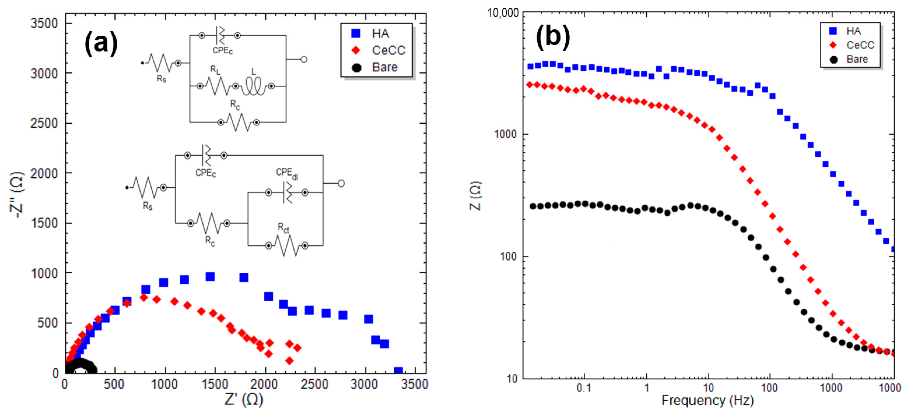
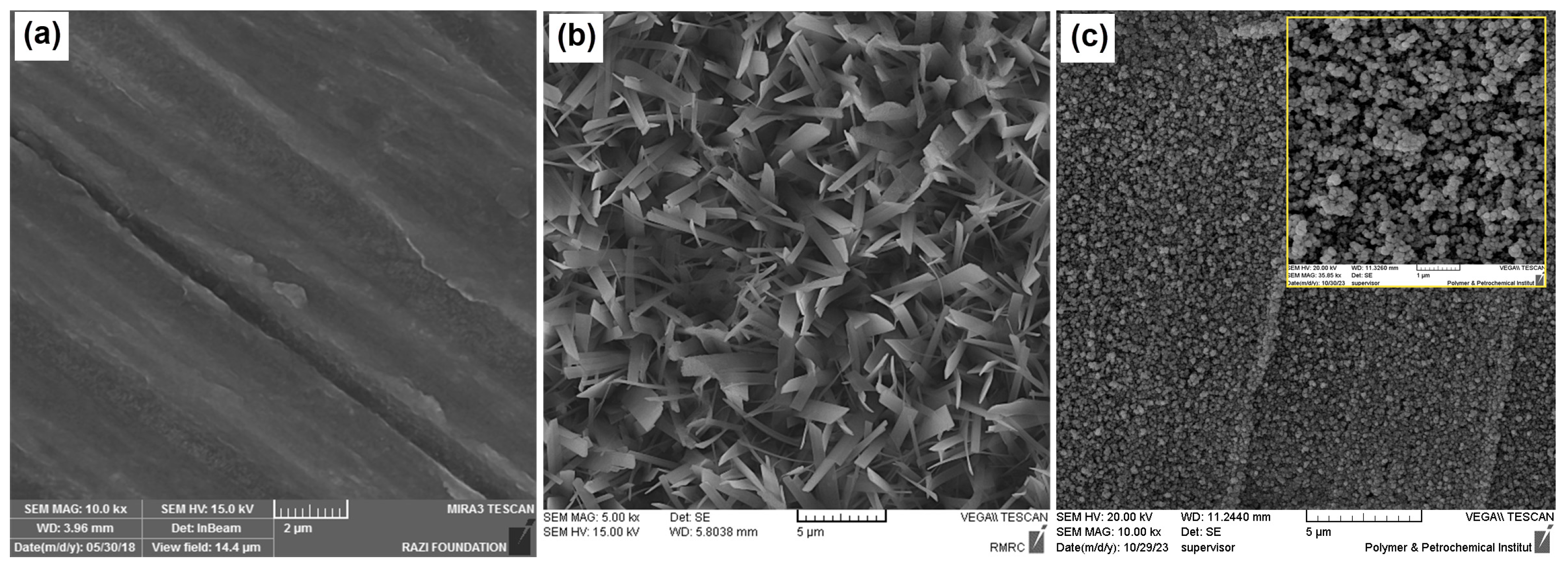
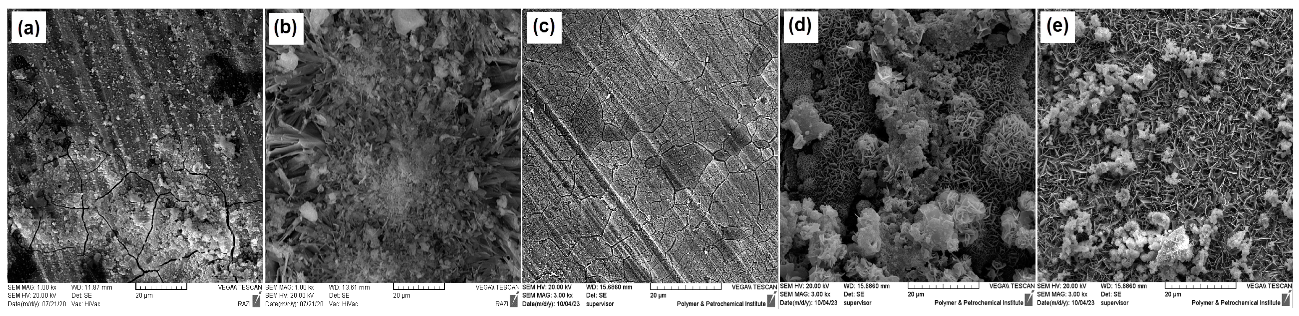
3.1.1. EIS and FE-SEM Study

Figure 1 shows the Nyquist and Bode curves derived from the EIS analysis for magnesium samples without coating, hydroxyapatite, and cerium conversion coating. The Nyquist curves were fitted and simulated with equivalent circuits embedded in the Nyquist curve, and the results obtained from the fitting are mentioned in Table 2. Also, Figure 2a shows the SEM image of the magnesium surface after the mentioned mechanical and chemical preparations in the experimental section, and clearly, a smooth and uniform surface with shallow and deep scratches from using the polishing sandpapers can be observed. The optimized hydroxyapatite coating in previous studies in Figure 2b shows a crystalline and porous structure similar to the morphology obtained in the work of Pou et al.’s research [17]. Also, Figure 2c shows the cerium conversion coating, which is a thin coating made of nanometric spherical particles, and a closer magnification of these particles is seen inside the image. Rs, Rc, and Rct parameters appear for the resistance of the solution, coating, and charge transfer, respectively. It should be noted that polarization resistance is the sum of charge transfer and coating resistances (Rp = Rct + Rc) [44,45,46]. Also, RL represents the absorption and desorption resistance of ions in the interface and L is the induction parameter [47]. CPEc and CPEdl are the non-ideal capacitors related to the constant phase elements of the coating and charge transfer, respectively. The time constant at high frequency is attributed to the coating, and the one that appeared at low frequencies is related to the oxide film or the response of the interface to electrochemical reactions. According to the Nyquist curves, both hydroxyapatite coating and cerium conversion coating increased the polarization resistance (Rp) of the samples compared to uncoated magnesium, which was predictable. Two-time constants appear in the Nyquist diagram of the HA coating, which indicates the penetration of oxygen, water, and corrosive ions and the occurrence of electrochemical reactions as this coating is exposed to the test solution [48]. The polarization resistance of hydroxyapatite (HA) is equal to 3630 ohm·cm2 and for the cerium conversion coating (CeCC) is equal to 2430 ohm·cm2, whereas uncoated magnesium (Bare) has an Rp equal to 253 ohm·cm2.

3.1.2. Formation Mechanism

The process of Hydroxyapatite (HA) formation, as per prior findings [49], might involve a series of chemical reactions. The literature suggests that electrochemical reactions occur in active cathodic and anodic areas, which are rich in Aluminum and Magnesium, respectively. Given that the treatment solution has a pH of approximately 4, Mg2+ ions are released due to anodic dissolution, as per Equation (1). Conversely, cathodic reactions such as the reduction of water and soluble oxygen occur in the cathodic area, leading to an increase in local pH due to the production of OH (Equations (2) and (3)) [43,50]. Hydroxyl ions, as shown in Equations (2) and (3), establish beneficial locations for the selective formation of Hydroxyapatite (HA). This process occurs simultaneously with the deposition of hydrated magnesium on the base material. The proposed process for the deposition of HA and magnesium hydroxide is depicted in Equations (4)–(6) [51,52].
Anodic reaction: Mg → Mg2+ + 2e
Cathodic reaction: 2H2O + 2e → H2↑ + 2OH
O2 + 2H2O + 4e → 4OH
Mg2+ + Ca2+ + 2HPO42− + 4H2O → CaMgHPO4·4H2O↓
3Ca2+ + 2PO43− + 4H2O → Ca3(PO4)2·4H2O↓
Mg2+ + 2OH → Mg(OH)2
Recent studies indicate that the solubility of Magnesium hydroxide (10−1 mol/L) surpasses that of hydroxyapatite (1.3 × 10⁻⁶ mol/L) in water. As immersion time lengthens, the substrate’s exposure to Mg2+ becomes restricted due to the formation of HA and Mg(OH)2 layers on it, whereas the supply of Ca2+ remains constant. This leads to more frequent nucleation of HA compared to the precipitation of magnesium hydroxide, owing to its inferior solubility and the continuous availability of Ca2+ ions.
In parallel, cathodic reactions happen at the Al-rich β phase, reducing H2O and soluble oxygen at the cathodic areas (Equations (2) and (3)). The generation of hydroxyl ions in the cathodic regions results in a rise in local pH [53], but it is not sufficient for the precipitation of the Ce film. Hence, adding H2O2 to the cerium solutions speeds up the production of OH at the cathodic areas, significantly boosting the pH values at the interface [54,55,56] (Equation (7)):
H2O2 (aq) + 2e ⇌ 2OH (aq)
As a result, Ce3+ and Ce4+ ions undergo hydrolysis, leading to the growth of the cerium conversion coating through the precipitation of these cations as cerium hydroxides or CeO2 [57] in the cathodic areas (Equations (8) and (9)). Furthermore, in the presence of H2O2, Ce3+ is transformed into Ce4+ as per Equation (10) [58]:
Ce3+ (aq) + 3OH (aq) → Ce(OH)3 (s)
Ce4+ (aq) + 4OH (aq) → Ce(OH)4 (s)
2Ce3+ (aq) + H2O2 (aq) + 2OH (aq) → 2Ce(OH)22+ (aq)
H2O2 lead to the increase of pH value beyond 8, resulting in the conversion of cerium components to Ce(IV) [59]. This change indicates that the majority of the hydroxides is likely to be converted into oxides through the dehydration or oxidation of the precipitated compounds containing significant amounts of Ce(IV) [59,60] (Equations (11) and (12)):
Ce(OH)3 (s) → CeO2 (s) + H3O+ + e
Ce(OH)22+ (aq) + 2OH (aq) → CeO2 (s) + 2H2O

3.2. Modification of HA Coating with Ce

Cerium nitrate was used directly in the coating solution to modify the hydroxyapatite coating. The immersion time, as a highly influential parameter in the formation of the coating, was examined through EIS and SEM tests. Figure 3 indicates the Nyquist and Bode plots for hydroxyapatite + cerium coatings at different immersion times and film formation of 15 min, 30 min, and 60 min. Figure 4 also shows SEM images and the morphology of these samples at different magnifications. The EIS curves were fitted by single and double time-constant equivalent circuits shown in Figure 3, and the obtained parameters are reported in Table 3. According to Table 3, the lowest polarization resistance (Rp) belongs to the coating at the shortest time. This low resistance is fully justified by examining the SEM image of the surface of this sample. The lack of complete surface coverage and the lack of adequate time for the formation of coating crystals and their growth are clearly visible in Figure 4a–c. Therefore, many areas of the surface do not contain a coating and cannot protect the surface against corrosion. With the increase in the coating time from 15 min to 30 min and according to the images of Figure 4d,e, a change in the coverage and morphology of the coating is observed. Crystalline structures formed on the surface are visible, and according to the results of the EIS test at this coating time, the polarization resistance reaches 9152 ohm·cm2. With the increase in the coating time to one hour, according to Figure 4g–i, a crystalline coating appears on the surface, which seems to have slightly larger crystals and larger plates in the crystalline structure, and therefore has larger pores compared to the 30 min sample. This can be a reason for the drop in the anti-corrosion resistance of this sample according to the result of the EIS test, which shows a polarization resistance of about 7810 ohm·cm2 for this sample. Therefore, it can be said that the sample that was coated for 30 min in a solution containing hydroxyapatite and cerium shows the highest resistance against corrosion, and this sample was selected for application on the magnesium surface modified with cerium conversion coating.

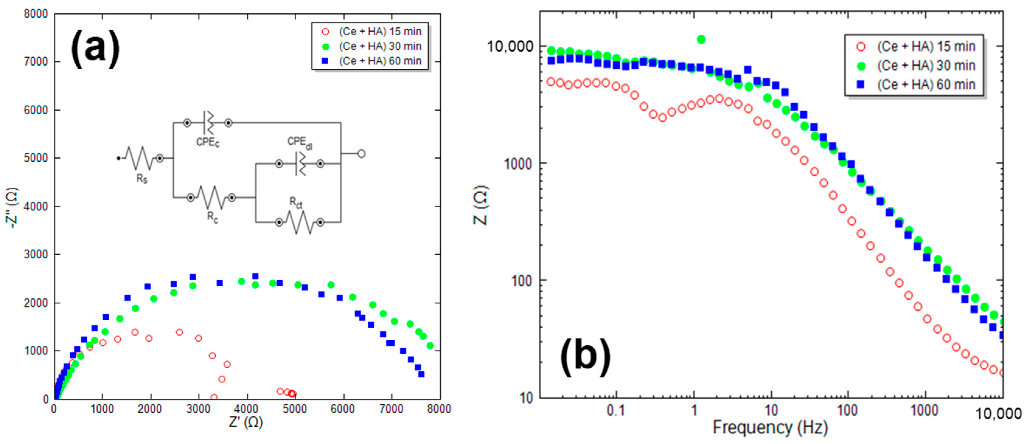
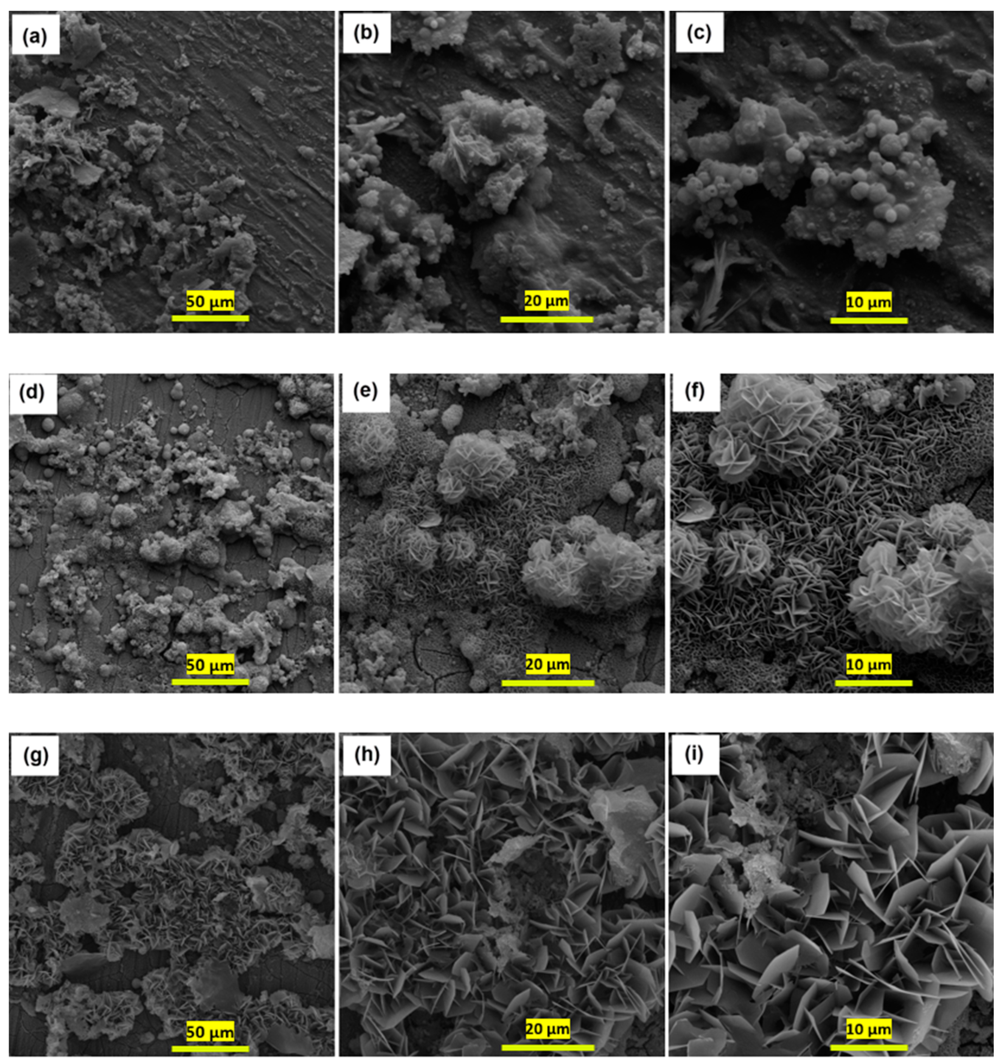
3.2.1. HA + Ce Coating on CeCC

The protective structure was further reinforced by applying a hydroxyapatite + cerium coating (obtained from the previous section) on the magnesium surface modified with a cerium-based conversion coating. Figure 5a shows the Nyquist plot of the Ce + HA/CeCC sample. According to the Nyquist plot and after fitting the data with a two-time constant equivalent circuit, the polarization resistance is Rp = 29,640 ohm·cm2. This is about a three-fold improvement in polarization resistance compared to the Ce + HA 30 min sample, and this resistance increase is about 8 and 12 times more compared to the HA sample and the CeCC sample, respectively. Figure 5b shows the surface morphology of this coating at two different magnifications, and it is clear that a uniform and dense crystalline coating has formed on the surface. If the electrolyte penetrates the pores of the coating, it will reach the cerium conversion coating surface in the next stage and face a new resistance in its path. This morphology and reinforced structure increased the corrosion resistance.

3.2.2. DC Polarization and OCP Measurements

Figure 6a shows the curve of OCP changes over time for samples immersed in a corrosive environment. All four samples under investigation show negative potential values at the start of the test. The trend of potential changes over time is not linear, which is due to different reactions occurring on the sample surface over time, as well as activation-repassivation processes taking shape on the sample surfaces. The porous nature of the coatings also affects this oscillatory trend of potential changes over time. At the start of the measurement, an increasing potential trend for the samples is observed, which could be due to the formation of corrosion products in the SBF solution, as mentioned in numerous studies [61]. The lowest and most negative potential throughout the measurement period belongs to the uncoated magnesium sample, which, as expected, has the weakest performance and shows the least resistance to corrosion. According to the HA chart, it is clear that the OCP is a little greater in positivity compared to the uncoated magnesium sample, reducing the electrochemical activity of the surface. In the presence of cerium and with the modification of the hydroxyapatite coating, the open circuit potential becomes more positive and nobler compared to HA, which could confirm the better protective behavior of the HA + Ce and HA + Ce/CeCC samples.
The results of the direct current polarization test are shown in Figure 6b, and the corrosion potential and corrosion current density values were calculated. The corrosion current density values for the HA (4.00 µA/cm2), HA + Ce (1.05 µA/cm2), and HA + Ce/CeCC (0.02 µA/cm2) coatings show a significant reduction compared to the Bare Mg AZ31 (14.01 µA/cm2). This indicates a better resistance of the modified coatings in the corrosive environment. Considering the Tafel slopes, compared to the uncoated magnesium alloy, slope changes have occurred in both the cathodic and anodic branches in the coated samples. According to the electron microscope images in the previous discussions, the applied coatings completely deposit on the surface. Initially, they occur in micro cathodes as a result of a local increase in pH, which is a suitable place for apatite deposition, and then growth occurs around it to uniformly cover the surface. As a result, both the anodic and cathodic branches are affected, and the slope of both has changed [48].

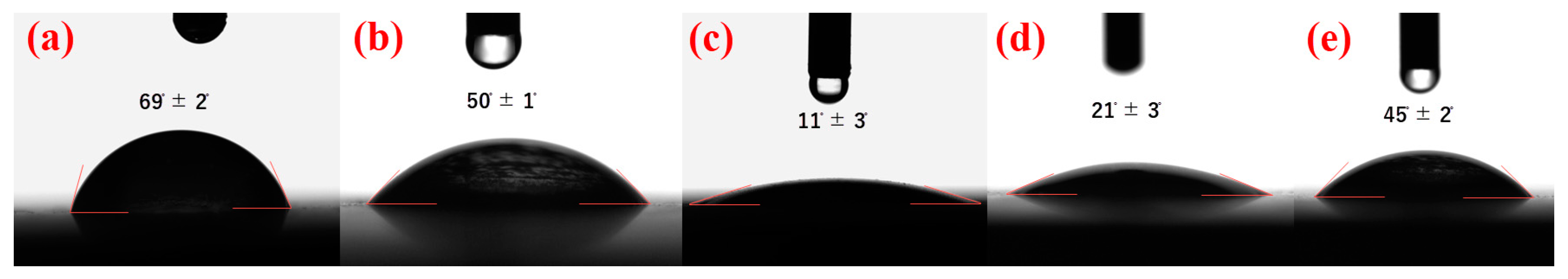
3.3. Contact Angle Study

In the following, the hydrophilic and hydrophobic properties of the sample surfaces were examined using a water droplet contact angle test. Figure 7 shows images of a water droplet placed on the surface of various samples. To better compare the effect of cerium on the hydrophilic nature of the surface, images of water droplets were also taken from the CeCC and HA samples, and the contact angles were determined. According to Figure 7a, the contact angle of a water droplet with the surface of an uncoated magnesium sample is about 70 degrees. In the case of a cerium conversion coating, this contact angle decreases and reaches an approximate number of 50 degrees, which is shown in Figure 7b. Coatings based on calcium phosphate and hydroxyapatite, as emphasized in various references, are very hydrophile [62,63], and here too, a very low contact angle of about 11 degrees is evident in Figure 7c. When measuring this contact angle, the droplet quickly spreads on the surface and after a few seconds, there is no possibility of measurement because practically all the volume of the water droplet has been absorbed by the surface. For the HA + Ce sample (Figure 7d), due to the presence of cerium in the coating, the hydrophilic nature of the coating is controlled and reached 21 degrees; in other words, it is not very hydrophile like HA and does not have a number close to 50 like CeCC. Finally, the HA + Ce/CeCC sample (Figure 7e) was also evaluated, and the image of the water droplet contact angle shows a value of about 45 degrees, which is closer to the CeCC contact angle; in other words, it shows the greater effect and presence of cerium in the surface properties of the coating.

3.4. XRD Study

Figure 8a shows the XRD pattern of the Mg AZ31 alloy without coating, with hydroxyapatite (HA) coating, cerium + hydroxyapatite (HA + Ce) coating, and cerium + hydroxyapatite applied on the surface of magnesium modified with cerium conversion coating (HA + Ce/CeCC). The X-ray diffraction pattern of the hydroxyapatite-based coating shows peaks at 2θ equal to 31°, 36°, 57°, and 63°, confirming the formation of hydroxyapatite crystals on the Mg AZ31 surface [62,64,65]. The diffraction pattern of the hydroxyapatite + cerium (HA + Ce) coating shows peaks at 2θ equal to 32° and 48° due to the presence of cerium in the coating that are consistent with the results obtained in the articles. In addition, in the diffraction pattern of the HA + Ce and HA + Ce/CeCC coatings, the intensity of Mg peaks decreased and could confirm that the coating is more uniform and thick. It should be noted that the presence of peaks at 32° and 48° in both HA + Ce and HA + Ce/CeCC coatings confirms the presence of cerium in the coatings. Additionally, the α and β variations of tricalcium phosphate (TCP), Ca3(PO4)2, and calcium oxide (CaO) have been identified in HA coatings. The XRD peaks observed in the range of 30.5° to 32.5° are indicative of the existence of β-TCP, whereas the peaks observed in the range of 36.0° to 38.5° suggest the presence of calcium oxide. The range between 38.5° and 59° is linked to the interference that results from α-TCP, β-TCP, calcium oxide, and maybe β-Ca2P2O7 to obtain the component of HA [66].
The HA formation on Mg is confirmed by the peaks in Figure 8b. The presence of phosphate groups is indicated by the peak at 1020 cm−1 [67]. The peak at 1650 cm−1 is due to the carbonate groups that might have formed on the Mg surface due to the reaction between CO2 and H2O on the prepared Mg surface. The natural HA structure is expected to contain carbonate groups [68], so it can be inferred that the HA structure is present on all coated Mg samples. Peaks in the wavenumber range of 2800–3600 cm−1 are caused by the (Ce-OH) structure, adsorbed water molecules, and (OH) in the HA structure. The (OH) peak’s intensity is notably higher in the CeCC sample than in other samples.

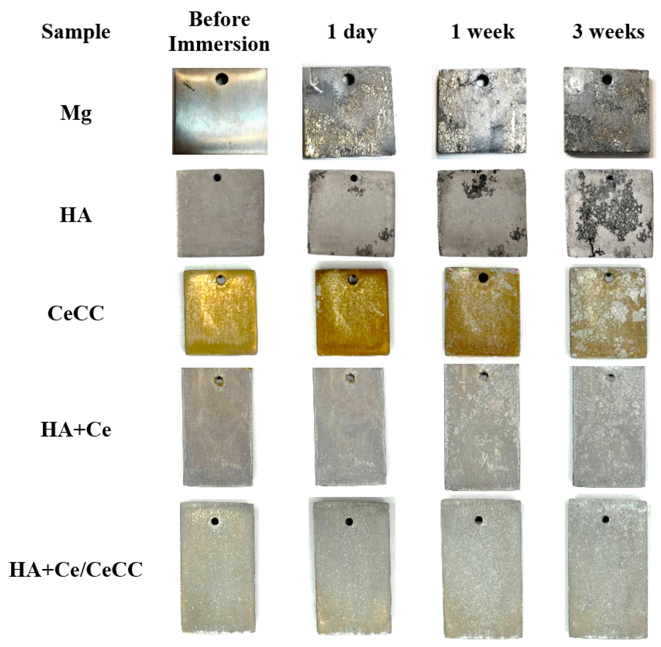
3.5. Immersion in SBF

Figure 9 reveals the surface images of the samples after immersion in SBF solution at immersion times of 1 day, 1 week, and 3 weeks. According to the surface images of the uncoated magnesium sample, the severe degradation process of this sample is evident over time, and even after one day, significant surface degradation is observed. For the sample that only has HA coating, very little corrosion is evident on the surface up to one week of immersion time. However, after 3 weeks of immersion, degradation and corrosion on the surface of the HA sample become apparent. The surface degradation process for the CeCC sample is also clearly visible and happens quickly. According to the HA + Ce images, no severe degradation is seen on the surface during the immersion time, but after one week of immersion, the surface of the coating becomes uneven and white deposits grow on the surface, which is much less for the HA + Ce/CeCC sample and happens later, indicating the proper performance of this reinforced coating.
Different samples were dipped in Simulated Body Fluid (SBF), and Electrochemical Impedance Spectroscopy (EIS) tests were carried out at certain times to study the biocorrosion behavior. Figure 10 shows the Nyquist plots of uncoated magnesium samples, HA, HA + Ce, and HA + Ce/CeCC at different immersion times (1 h, 1 day, 1 week, 2 weeks, and 3 weeks) in SBF solution. The Nyquist plots in this figure are fitted by an equivalent circuit with two time constants. Table 4 and Table 5 contain the results from the EIS test that were obtained after the fitting process. It should be noted that the fitting error of the results is less than 8 and 9 percent, respectively.
After 3 weeks of immersion in SBF media, the polarization resistance of all samples significantly decreased. The decrease in polarization resistance in the HA + Ce/CeCC coating is less compared to other coatings, and its value is approximately 4.5 times the polarization resistance of the hydroxyapatite coating with similar immersion time. In fact, the presence of a dense and reinforced layer of hydroxyapatite + cerium on the cerium conversion coating blocks the path of corrosive species and has less permeability [69,70].
Figure 11 presents the FE-SEM micrographs of the bare Mg alloy and the coated samples after being soaked in a simulated body fluid for one week. As per Figure 11a, after being submerged for one week, the uncoated magnesium alloy starts to show signs of corrosion on its surface, and corrosion cracks become visible on its surface. As shown in Figure 11b, the morphology of the HA sample surface changed, and its cluster-like structures degraded, which could affect the long-term protection of this coating. Also, when the cerium conversion coating is used alone, it undergoes degradation and numerous micro-cracks after one week of immersion in SBF, and as a result, it cannot provide adequate protective performance (Figure 11c). However, for the HA + Ce and HA + Ce/CeCC coatings (Figure 11d,e), after one week of immersion, the coating surface underwent minor changes, and a series of white deposits formed on the coating surface, and the coatings managed to maintain their protective performance according to the EIS test results.
Figure 12 illustrates the outcomes of hydrogen evolution and pH fluctuations for Bare Mg, HA, HA + Ce, and HA + Ce/CeCC specimens submerged in the SBF solution for a duration of 180 h. The swift surge in the initial pH for all specimens is primarily due to the discharge of OH ions at micro-cathodic locations (Figure 12a). Nevertheless, during the immersion process, the pH levels of the SBF solution for the coated specimens were noticeably less than those of the uncoated specimen. The pH level in the vicinity of implants is a crucial determinant that can influence cell differentiation, proliferation, and function [71,72,73]. Particularly for the specimen coated with the HA + Ce/CeCC layer, the minimal inclination in the pH value increase signifies that the CeCC pretreatment coating approach was superior for protecting the Mg AZ31 substrate. Moreover, the quantity of hydrogen released by the coated specimens (Figure 12b) during the immersion test was considerably less than that of the uncoated specimens, aligning with the pH value outcomes. The swift generation of hydrogen led to emphysema, potentially delaying the healing process of the surgical area, resulting in tissue necrosis and discomfort. Consequently, the CeCC pretreatment significantly postponed the degradation of the specimens due to the effective protection provided by the HA + Ce coating and the enhanced adhesion force at the interface.

4. Conclusions

In this study, the role of cerium as a modifier for hydroxyapatite coating was examined in terms of corrosion resistance and performance in an SBF environment. Cerium was used as a modifier in two states: when cerium was directly added to hydroxyapatite (HA + Ce) and when cerium was applied as a pre-treatment step and as a conversion coating on the magnesium surface (HA + Ce/CeCC). Both cases showed improvements in uniformity and coating formation, along with increased corrosion resistance. Initially, the electrochemical behavior and performance of the coatings were evaluated by EIS, DC Polarization, and OCP tests, and the results indicated the effective performance of cerium as a coating modifier, which led to an increase in polarization resistance (Rp), a decrease in corrosion current density (icorr), and a more positive OCP value of the HA coating. In the final step, the behavior of these coated samples in the SBF environment was examined over time. The EIS results over time showed that the HA + Ce/CeCC sample reaches a polarization resistance of about 15,000 ohm·cm2 after 3 weeks of immersion, which shows a suitable improvement compared to other samples. The hydrogen evolution test showed that the rate of hydrogen release in the presence of the cerium modifier is much lower than the uncoated magnesium sample. Finally, it can be said that when the cerium conversion coating is placed as an intermediate layer between HA and the magnesium surface, it causes better adhesion of the coating to the surface, and when used alongside HA within the coating, by controlling film formation and changing surface morphology, it can improve the corrosion resistance performance of magnesium implants.

Author Contributions

Conceptualization, H.E.M.; methodology, Z.R. and H.E.M.; software, H.E.M.; validation, F.A.T. and S.P.; writing—original draft, Z.R.; writing—review & editing, H.E.M.; supervision, F.A.T., S.P. and H.E.M. All authors have read and agreed to the published version of the manuscript.

Funding

This research received no external funding.

Institutional Review Board Statement

Not applicable.

Informed Consent Statement

Not applicable.

Data Availability Statement

Data are contained within the article.

Conflicts of Interest

The authors declare no conflicts of interest.

References

  1. Niu, L.Y.; Jiang, Z.H.; Li, G.Y.; Gu, C.D.; Lian, J.S. A study and application of zinc phosphate coating on AZ91D magnesium alloy. Surf. Coat. Technol. 2006, 200, 3021–3026. [Google Scholar] [CrossRef]
  2. Staiger, M.P.; Pietak, A.M.; Huadmai, J.; Dias, G. Magnesium and its alloys as orthopedic biomaterials: A review. Biomaterials 2006, 27, 1728–1734. [Google Scholar] [CrossRef] [PubMed]
  3. Hollstein, F.; Wiedemann, R.; Scholz, J. Characteristics of PVD-coatings on AZ31hp magnesium alloys. Surf. Coat. Technol. 2003, 162, 261–268. [Google Scholar] [CrossRef]
  4. Jayasathyakawin, S.; Ravichandran, M.; Baskar, N.; Chairman, C.A.; Balasundaram, R. Mechanical properties and applications of Magnesium alloy—Review. Mater. Today Proc. 2020, 27, 909–913. [Google Scholar] [CrossRef]
  5. Zhong, C.; Liu, F.; Wu, Y.; Le, J.; Liu, L.; He, M.; Zhu, J.; Hu, W. Protective diffusion coatings on magnesium alloys: A review of recent developments. J. Alloys Compd. 2012, 520, 11–21. [Google Scholar] [CrossRef]
  6. Chen, X.B.; Birbilis, N.; Abbott, T.B. A simple route towards a hydroxyapatite-Mg(OH)2 conversion coating for magnesium. Corros. Sci. 2011, 53, 2263–2268. [Google Scholar] [CrossRef]
  7. Jeong, Y.S.; Kim, W.J. Enhancement of mechanical properties and corrosion resistance of Mg-Ca alloys through microstructural refinement by indirect extrusion. Corros. Sci. 2014, 82, 392–403. [Google Scholar] [CrossRef]
  8. Li, Q.; Ye, W.; Gao, H.; Gao, L. Improving the corrosion resistance of ZEK100 magnesium alloy by combining high-pressure torsion technology with hydroxyapatite coating. Mater. Des. 2019, 181, 107933. [Google Scholar] [CrossRef]
  9. Ronc, I.S.; Grubac, Z.; Metikos, M. Electrodeposition of hydroxyapatite coating on AZ91D alloy for biodegradable implant application. Int. J. Electrochem. Sci. 2014, 9, 5907–5923. [Google Scholar] [CrossRef]
  10. Ho, Y.H.; Man, K.; Joshi, S.S.; Pantawane, M.V.; Wu, T.C.; Yang, Y.; Dahotre, N.B. In-vitro biomineralization and biocompatibility of friction stir additively manufactured AZ31B magnesium alloy-hydroxyapatite composites. Bioact. Mater. 2020, 5, 891–901. [Google Scholar] [CrossRef]
  11. Ren, Y.; Babaie, E.; Bhaduri, S.B. Nanostructured amorphous magnesium phosphate/poly (lactic acid) composite coating for enhanced corrosion resistance and bioactivity of biodegradable AZ31 magnesium alloy. Prog. Org. Coat. 2018, 118, 1–8. [Google Scholar] [CrossRef]
  12. Durdu, S.; Bayramoglu, S.; Demirtaş, A.; Usta, M.; Üçşk, A.H. Characterization of AZ31 Mg Alloy coated by plasma electrolytic oxidation. Vacuum 2013, 88, 130–133. [Google Scholar] [CrossRef]
  13. Nabizadeh, M.; Sarabi, A.A.; Mohammadloo, H.E. Comparative investigation of Cu ion and adipic acid addition on electrochemical and microstructure characteristics of vanadium conversion coating on AZ31 Mg alloy. Surf. Coat. Technol. 2019, 357, 1–11. [Google Scholar] [CrossRef]
  14. Yue, J.; Lou, G.; Zhou, G.; Leng, J.; Feng, Y.; Teng, X. Corrosion resistance of zinc phosphate conversion coatings on az91d surface. Mater. Sci. Forum Trans. Tech. Publ. 2020, 993, 1110–1117. [Google Scholar] [CrossRef]
  15. Van Phuong, N.; Lee, K.; Chang, D.; Kim, M.; Lee, S.; Moon, S. Zinc phosphate conversion coatings on magnesium alloys: A review. Met. Mater. Int. 2013, 19, 273–281. [Google Scholar] [CrossRef]
  16. Narayanan, T.S.N.S. Surface pretreatment by phosphate conversion coatings—A review. Rev. Adv. Mater. Sci. 2005, 9, 130–177. [Google Scholar]
  17. Cui, L.Y.; Cheng, S.C.; Liang, L.X.; Zhang, J.C.; Li, S.Q.; Wang, Z.L.; Zeng, R.C. In vitro corrosion resistance of layer-by-layer assembled polyacrylic acid multilayers induced Ca–P coating on magnesium alloy AZ31. Bioact. Mater. 2020, 5, 153–163. [Google Scholar] [CrossRef]
  18. Yadav, V.S.; Kumar, A.; Das, A.; Pamu, D.; Pandey, L.M.; Sankar, M.R. Degradation kinetics and surface properties of bioceramic hydroxyapatite coated AZ31 magnesium alloys for biomedical applications. Mater. Lett. 2020, 270, 127732. [Google Scholar] [CrossRef]
  19. Saei, E.; Ramezanzadeh, B.; Amini, R.; Kalajahi, M.S. Effects of combined organic and inorganic corrosion inhibitors on the nanostructure cerium based conversion coating performance on AZ31 magnesium alloy: Morphological and corrosion studies. Corros. Sci. 2017, 127, 186–200. [Google Scholar] [CrossRef]
  20. Zhu, W.; Chen, F.; Yi, A.; Liao, Z.; Li, W.; Li, K.; Chen, K.; Liang, G.; Guo, J.T.; Wu, Q. Titanium, zirconium and vanadium conversion coatings (TZVCCs) on AZ91D magnesium alloy sheets. Mater. Res. Express. 2020, 7, 86402. [Google Scholar] [CrossRef]
  21. Guo, Y.; Su, Y.; Gu, R.; Zhang, Z.; Li, G.; Lian, J.; Ren, L. Enhanced corrosion resistance and biocompatibility of biodegradable magnesium alloy modified by calcium phosphate/collagen coating. Surf. Coat. Technol. 2020, 401, 127322. [Google Scholar] [CrossRef]
  22. Seitz, J.M.; Collier, K.; Wulf, E.; Bormann, D.; Bach, F.W. Comparison of the Corrosion Behavior of Coated and Uncoated Magnesium Alloys in an In Vitro Corrosion Environment. Adv. Eng. Mater. 2011, 13, B313–B323. [Google Scholar] [CrossRef]
  23. Hahn, B.-D.; Park, D.-S.; Choi, J.-J.; Ryu, J.; Yoon, W.-H.; Choi, J.-H.; Kim, H.-E.; Kim, S.-G. Aerosol deposition of hydroxyapatite–chitosan composite coatings on biodegradable magnesium alloy. Surf. Coat. Technol. 2011, 205, 3112–3118. [Google Scholar] [CrossRef]
  24. Rahimi, M.; Aghdam, R.M.; Sohi, M.H.; Rezayan, A.H.; Ettelaei, M. Improving biocompatibility and corrosion resistance of anodized AZ31 Mg alloy by electrospun chitosan/mineralized bone allograft (MBA) nanocoatings. Surf. Coat. Technol. 2021, 405, 126627. [Google Scholar] [CrossRef]
  25. Chen, X.B.; Nisbet, D.R.; Li, R.W.; Smith, P.N.; Abbott, T.B.; Easton, M.A.; Zhang, D.H.; Birbilis, N. Controlling initial biodegradation of magnesium by a biocompatible strontium phosphate conversion coating. Acta Biomater. 2014, 10, 1463–1474. [Google Scholar] [CrossRef]
  26. Astala, R.; Stott, M.J. First principles investigation of mineral component of bone: CO3 substitutions in hydroxyapatite. Chem. Mater. 2005, 17, 4125–4133. [Google Scholar] [CrossRef]
  27. Ahmadi, H.; Ghamsarizade, R.; Haddadi-Asl, V.; Mohammadloo, H.E.; Ramezanzadeh, B. Designing a novel bio-compatible hydroxyapatite (HA)/hydroxyquinoline (8-HQ)-inbuilt polyvinylalcohol (PVA) composite coatings on Mg AZ31 implants via electrospinning and immersion protocols: Smart anti-corrosion and anti-bacterial properties reinforcements. J. Ind. Eng. Chem. 2022, 116, 556–571. [Google Scholar] [CrossRef]
  28. Negroiu, G.; Piticescu, R.M.; Chitanu, G.C.; Mihailescu, I.N.; Zdrentu, L.; Miroiu, M. Biocompatibility evaluation of a novel hydroxyapatite-polymer coating for medical implants (in vitro tests). J. Mater. Sci. Mater. Med. 2008, 19, 1537–1544. [Google Scholar] [CrossRef]
  29. Zomorodian, A.; Garcia, M.P.; Silva, T.M.E.; Fernandes, J.C.S.; Fernandes, M.H.; Montemor, M.D.F. Biofunctional composite coating architectures based on polycaprolactone and nanohydroxyapatite for controlled corrosion activity and enhanced biocompatibility of magnesium AZ31 alloy. Mater. Sci. Eng. C 2015, 48, 434–443. [Google Scholar] [CrossRef]
  30. Jamesh, M.; Kumar, S.; Narayanan, T.S.N.S. Electrodeposition of hydroxyapatite coating on magnesium for biomedical applications. J. Coat. Technol. Res. 2012, 9, 495–502. [Google Scholar] [CrossRef]
  31. Sreekanth, D.; Rameshbabu, N. Development and characterization of MgO/hydroxyapatite composite coating on AZ31 magnesium alloy by plasma electrolytic oxidation coupled with electrophoretic deposition. Mater. Lett. 2012, 68, 439–442. [Google Scholar] [CrossRef]
  32. Dorozhkin, S.V. Calcium orthophosphate coatings on magnesium and its biodegradable alloys. Acta Biomater. 2014, 10, 2919–2934. [Google Scholar] [CrossRef]
  33. Zhou, Z.; Zheng, B.; Gu, Y.; Shen, C.; Wen, J.; Meng, Z.; Chen, S.; Ou, J.; Qin, A. New approach for improving anticorrosion and biocompatibility of magnesium alloys via polydopamine intermediate layer-induced hydroxyapatite coating. Surf. Interfaces 2020, 19, 100501. [Google Scholar] [CrossRef]
  34. Jian, S.-Y.; Yang, C.-Y.; Chang, J.-K. Robust corrosion resistance and self-healing characteristics of a novel Ce/Mn conversion coatings on EV31 magnesium alloys. Appl. Surf. Sci. 2020, 510, 145385. [Google Scholar] [CrossRef]
  35. Hsieh, C.-Y.; Huang, S.-Y.; Chu, Y.-R.; Yen, H.-W.; Lin, H.-C.; Shih, D.S.; Kawamura, Y.; Lee, Y.-L. Role of second phases in the corrosion resistance and cerium conversion coating treatment of as-extruded Mg–8Al–4Ca magnesium alloy. J. Mater. Res. Technol. 2023, 22, 2343–2359. [Google Scholar] [CrossRef]
  36. Khast, F.; Saybani, M.; Dariani, A.A.S. Effects of copper and manganese cations on cerium-based conversion coating on galvanized steel: Corrosion resistance and microstructure characterizations. J. Rare Earths. 2022, 40, 1002–1006. [Google Scholar] [CrossRef]
  37. Wu, G.; Wang, C.; Zhang, Q.; Kang, P. Characterization of Ce conversion coating on Gr-f/6061Al composite surface for corrosion protection. J. Alloys Compd. 2008, 461, 389–394. [Google Scholar] [CrossRef]
  38. Lin, C.S.; Fang, S.K. Formation of cerium conversion coatings on AZ31 magnesium alloys. J. Electrochem. Soc. 2005, 152, B54–B59. [Google Scholar] [CrossRef]
  39. Lee, Y.L.; Chu, Y.R.; Lin, C.S. Mechanism of the formation of stannate and cerium conversion coatings on AZ91D magnesium alloys. Appl. Surf. Sci. 2013, 276, 578–585. [Google Scholar] [CrossRef]
  40. Lee, Y.L.; Chen, F.J.; Lin, C.S. Corrosion resistance studies of cerium conversion coating with a fluoride-free pretreatment on AZ91D magnesium alloy. J. Electrochem. Soc. 2013, 160, C28–C35. [Google Scholar] [CrossRef]
  41. Kazemi, S.; Ghamsarizade, R.; Yazdani, S.; Mohammadloo, H.E.; Yeganeh, H. The combined effect of hydroxyapatite and zirconia coatings on magnesium-based-implant to improve corrosion resistance and induce antibacterial activity. J. Alloys Compd. 2024, 971, 172790. [Google Scholar] [CrossRef]
  42. AhadiParsa, M.; Mohammadloo, H.E.; Mirabedini, S.M.; Roshan, S. Bio-corrosion assessment and surface study of hydroxyapatite-coated AZ31 Mg alloy pre-treated with vinyl tri-ethoxy silane. Mater. Chem. Phys. 2022, 287, 126147. [Google Scholar] [CrossRef]
  43. Afshari, M.; Mohammadloo, H.E.; Sarabi, A.A.; Roshan, S. Modification of hydroxyapatite-based coating in the presence of polyvinylalcohol (PVA) for implant application: Corrosion, structure and surface study. Corros. Sci. 2021, 192, 109859. [Google Scholar] [CrossRef]
  44. Mohammadloo, H.E.; Sarabi, A.A.; Hosseini, R.M.; Sarayloo, M.; Sameie, H.; Salimi, R. A comprehensive study of the green hexafluorozirconic acid-based conversion coating. Prog. Org. Coat. 2014, 77, 322–330. [Google Scholar] [CrossRef]
  45. Mohammadloo, H.E.; Sarabi, A.A.; Alvani, A.A.S.; Salimi, R.; Sameie, H. The effect of solution temperature and pH on corrosion performance and morphology of nanoceramic-based conversion thin film. Mater. Corros. 2013, 64, 535–543. [Google Scholar] [CrossRef]
  46. Ramezanzadeh, B.; Attar, M.M.; Farzam, M. A study on the anticorrosion performance of the epoxy-polyamide nanocomposites containing ZnO nanoparticles. Prog. Org. Coat. 2011, 72, 410–422. [Google Scholar] [CrossRef]
  47. Lostak, T.; Krebs, S.; Maljusch, A.; Gothe, T.; Giza, M.; Kimpel, M.; Flock, J.; Schulz, S. Formation and characterization of Fe3+-/Cu2+-modified zirconium oxide conversion layers on zinc alloy coated steel sheets. Electrochim. Acta. 2013, 112, 14–23. [Google Scholar] [CrossRef]
  48. Asemabadi, Z.; Korrani, A.M.; Dolatabadi, M.M.; Mohammadloo, H.E.; Sarabi, A.A.; Roshan, S. Modification of hydroxyapatite coating in the presence of adipic acid for Mg-based implant application. Prog. Org. Coat. 2022, 172, 107088. [Google Scholar] [CrossRef]
  49. Ji, X.-J.; Cheng, Q.; Wang, J.; Zhao, Y.-B.; Han, Z.-Z.; Zhang, F.; Li, S.-Q.; Zeng, R.-C.; Wang, Z.-L. Corrosion resistance and antibacterial effects of hydroxyapatite coating induced by polyacrylic acid and gentamicin sulfate on magnesium alloy. Front. Mater. Sci. 2019, 13, 87–98. [Google Scholar] [CrossRef]
  50. Bakhsheshi-Rad, H.R.; Hamzah, E.; Shuang, C.P.; Berto, F. Preparation of poly(ε-caprolactone)-hydroxyapatite composite coating for improvement of corrosion performance of biode-gradable magnesium. Mater. Des. Process. Commun. 2020, 2, e170. [Google Scholar] [CrossRef]
  51. Kiahosseini, S.R.; Afshar, A.; Larijani, M.M.; Yousefpour, M. Structural and corrosion characterization of hydroxyapatite/zirconium nitride-coated AZ91 magnesium alloy by ion beam sputtering. Appl. Surf. Sci. 2017, 401, 172–180. [Google Scholar] [CrossRef]
  52. Roshan, S.; Mohammadloo, H.E.; Sarabi, A.A.; Afshari, M. Biocompatible hybrid chitosan/hydroxyapatite coating applied on the AZ31 Mg alloy substrate: In-vitro corrosion, surface and structure studies. Mater. Today Commun. 2022, 30, 103153. [Google Scholar] [CrossRef]
  53. Lu, C.; Mu, S.; Du, J.; Zhang, K.; Guo, M.; Chen, L. Investigation on the composition and corrosion resistance of cerium-based conversion treatment by alkaline methods on aluminum alloy 6063. RSC Adv. 2020, 10, 36654–36666. [Google Scholar] [CrossRef]
  54. Ardelean, H.; Frateur, I.; Marcus, P. Corrosion protection of magnesium alloys by cerium, zirconium and niobium-based conversion coatings. Corros. Sci. 2008, 50, 1907–1918. [Google Scholar] [CrossRef]
  55. Scholes, F.; Soste, C.; Hughes, A.; Hardin, S.; Curtis, P. The role of hydrogen peroxide in the deposition of cerium-based conversion coatings. Appl. Surf. Sci. 2006, 253, 1770–1780. [Google Scholar] [CrossRef]
  56. Wang, C.; Jiang, F.; Wang, F. Cerium chemical conversion coating for aluminum alloy 2024-T3 and its corrosion resistance. Corrosion 2004, 60, 237–243. [Google Scholar] [CrossRef]
  57. Wheeler, D.W. Kinetics and mechanism of the oxidation of cerium in air at ambient temperature. Corros. Sci. 2016, 111, 52–60. [Google Scholar] [CrossRef]
  58. Gnedenkov, A.S.; Sinebryukhov, S.L.; Mashtalyar, D.V.; Gnedenkov, S.V. Localized corrosion of the Mg alloys with inhibitor-containing coatings: SVET and SIET studies. Corros. Sci. 2016, 102, 269–278. [Google Scholar] [CrossRef]
  59. Aldykiewicz, A.; Davenport, A.; Isaacs, H. Studies of the formation of cerium-rich protective films using X-ray absorption near-edge spectroscopy and rotating disk electrode methods. J. Electrochem. Soc. 2016, 143, 147–154. [Google Scholar] [CrossRef]
  60. Decroly, A.; Petitjean, J.-P. Study of the deposition of cerium oxide by conversion on to aluminium alloys. Surf. Coat. Technol. 2005, 194, 1–9. [Google Scholar] [CrossRef]
  61. Jayaraj, J.; Raj, S.A.; Srinivasan, A. Composite magnesium phosphate coatings for improved corrosion resistance of magnesium AZ31 alloy. Corros. Sci. 2016, 113, 104–115. [Google Scholar] [CrossRef]
  62. Qiu, D.; Wang, A.; Yin, Y. Characterization and corrosion behavior of hydroxyapatite/zirconia composite coating on NiTi fabricated by electrochemical deposition. Appl. Surf. Sci. 2010, 257, 1774–1778. [Google Scholar] [CrossRef]
  63. Yang, Y.; Kim, K.H.; Ong, J.L. A review on calcium phosphate coatings produced using a sputtering process—An alternative to plasma spraying. Biomaterials 2005, 26, 327–337. [Google Scholar] [CrossRef] [PubMed]
  64. Van Phuong, N.; Moon, S. Comparative corrosion study of zinc phosphate and magnesium phosphate conversion coatings on AZ31 Mg alloy. Mater. Lett. 2014, 122, 341–344. [Google Scholar] [CrossRef]
  65. Kim, M.S.; Ryu, J.J.; Sung, Y.M. One-step approach for nano-crystalline hydroxyapatite coating on titanium via micro-arc oxidation. Electrochem. Commun. 2007, 9, 1886–1891. [Google Scholar] [CrossRef]
  66. Prevéy, P.S. X-ray diffraction characterization of crystallinity and phase composition in plasma-sprayed hydroxyapatite coatings. J. Therm. Spray. Technol. 2000, 9, 369–376. [Google Scholar] [CrossRef]
  67. Sroka-Bartnicka, A.; Borkowski, L.; Ginalska, G.; Ślósarczyk, A.; Kazarian, S.G. Structural transformation of synthetic hydroxyapatite under simulated in vivo conditions studied with ATR-FTIR spectroscopic imaging. Spectrochim. Acta A Mol. Biomol. Spectrosc. 2017, 171, 155–161. [Google Scholar] [CrossRef]
  68. Gheisari, H.; Karamian, E.; Abdellahi, M. A novel hydroxyapatite–Hardystonite nanocomposite ceramic. Ceram. Int. 2015, 41, 5967–5975. [Google Scholar] [CrossRef]
  69. Ahmed, Y.; Rehman, M.A.U. Improvement in the surface properties of stainless steel via zein/hydroxyapatite composite coatings for biomedical applications. Surf. Interfaces 2020, 20, 100589. [Google Scholar] [CrossRef]
  70. Corradini, E.; Curti, P.S.; Meniqueti, A.B.; Martins, A.F.; Rubira, A.F.; Muniz, E.C. Recent advances in food-packing, pharmaceutical and biomedical applications of zein and zein-based materials. Int. J. Mol. Sci. 2014, 15, 22438–22470. [Google Scholar] [CrossRef]
  71. Yan, T.T.; Tan, L.L.; Xiong, D.S.; Liu, X.J.; Zhang, B.C.; Yang, K. Fluoride treatment and in vitro corrosion behavior of an AZ31B magnesium alloy. Mater. Sci. Eng. 2010, 30, 740–748. [Google Scholar] [CrossRef]
  72. Bakhsheshi-Rad, H.R.; Hamzah, E.; Daroonparvar, M.; Kasiri-Asgarani, M.; Medraj, M. Synthesis and biodegradation evaluation of nano-Si and nano-Si/TiO2 coatings on biodegradable Mg–Ca alloy in simulated body fluid. Ceram. Int. 2014, 40, 14009–14018. [Google Scholar] [CrossRef]
  73. Kotharu, V.; Nagumothu, R.; Arumugam, C.B.; Veerappan, M.; Sankaran, S.; Davoodbasha, M.; Nooruddin, T. Fabrication of corrosion resistant, bioactive and antibacterial silver substituted hydroxyapatite/titania composite coating on Cp Ti. Ceram. Int. 2012, 38, 731–740. [Google Scholar] [CrossRef]
Figure 1. Obtained Nyquist (a) and Bode (b) plots for Bare Mg, HA, and CeCC samples.
Coatings 14 00179 g001
Figure 2. Images obtained from FE-SEM analysis of Bare Mg (a), HA (b), and CeCC (c) samples.
Coatings 14 00179 g002
Figure 3. Obtained Nyquist (a) and Bode (b) plots for hydroxyapatite + cerium coatings at different immersion times of 15 min, 30 min, and 60 min.
Coatings 14 00179 g003
Figure 4. FE-SEM images for samples immersed 15 min (ac), 30 min (df), and 60 min (gi) in hydroxyapatite + cerium solution (pH = 4.3, temperature = 30 °C, [HA] = 1 gr/L and [Ce] = 1 gr/L).
Coatings 14 00179 g004
Figure 5. Nyquist plots of different samples (a) and FE-SEM images (b) for HA + Ce on CeCC sample in different magnifications.
Coatings 14 00179 g005
Figure 6. Open circuit potential (a) and polarization (b) graphs for Mg Bare, HA, HA + Ce, and HA + Ce/CeCC samples.
Coatings 14 00179 g006
Figure 7. Water contact angle measurements for uncoated Magnesium alloy (a), CeCC (b), HA (c), HA + Ce (d), and HA + Ce/CeCC (e) samples.
Coatings 14 00179 g007
Figure 8. XRD patterns (a) and ATR results (b) for different samples.
Coatings 14 00179 g008
Figure 9. Optical images of bare Mg, HA, CeCC, HA + Ce, and HA + Ce/CeCC samples after different immersion times in SBF media.
Coatings 14 00179 g009
Figure 10. Nyquist plots of the samples through immersion in the SBF solution at various immersion times of, 1 h, 1 day, 1 week, and 2 and 3 weeks for Mg Bare (a), HA (b), HA + Ce (c), and HA + Ce/CeCC (d) coated samples.
Coatings 14 00179 g010
Figure 11. FE-SEM micrographs of Bare Mg alloy (a), HA (b), CeCC (c), HA + Ce (d), and HA + Ce/CeCC (e) samples following a one-week soak in Simulated Body Fluid.
Coatings 14 00179 g011
Figure 12. (a) Change in pH value and (b) hydrogen evolution for the Mg bare, HA, HA + Ce, and HA + Ce/CeCC samples during immersion in SBF for 180 h.
Coatings 14 00179 g012
Table 1. Required specifications and compositions for Simulated Body Fluid (SBF) preparation.
ReagentsAmount in 1000 mL
NaCl8.035 g
NaHCO30.355 g
KCl0.225 g
K2HPO4·3H2O0.231 g
MgCl2·6H2O0.311 g
1.0 M HCl39.0 mL
CaCl20.292 g
Na2SO40.072 g
((HOCH2)3CNH2)6.118 g
1.0 M HClfor adjusting the pH~7.4
Table 2. Results Obtained from impedance measurements for the bare, HA-coated, and CeCC samples.
SampleRS
(Ω·cm2)
Rc
(Ω·cm2)
Rct
(Ω·cm2)
Rp
(Ω·cm2)
n1Y0 (1)
(sn/Ω/cm2)
n2Y0 (2)
(sn/Ω/cm2)
Bare13.5-2532530.9255.60--
HA6.12602102836300.8818.110.908.90
CeCC11.2-243024300.9022.70--
Table 3. Electrochemical data for the hydroxyapatite + cerium coatings at different immersion times of 15, 30, and 60 min.
SampleRS
(Ω·cm2)
Rc
(Ω·cm2)
Rct
(Ω·cm2)
Rp
(Ω·cm2)
n1Y0 (1)
(sn/Ω/cm2)
n2Y0 (2)
(sn/Ω/cm2)
Ce + HA 15 min18.501498352250200.788.050.8311.43
Ce + HA 30 min25.773472568091520.8912.770.814.72
Ce + HA 60 min26.123145466578100.9015.200.857.86
Table 4. Obtained electrochemical impedance data for the Bare Mg AZ31 and HA samples after different times of immersion in the SBF media.
Immersion TimeRs
(Ω·cm2)
Rc
(Ω·cm2)
Rct
(Ω·cm2)
Rp
(Ω·cm2)
Bare AZ31
1 h24.80370-370
1 day49.55506-506
1 week38.20727-727
2 weeks13.85510-510
3 weeks12.59312-312
HA
1 h9.218110411912,229
1 day13.3535527134265
1 week10.50289112094100
2 weeks14.1299122243215
3 weeks12.623625012537
For this table, the standard deviation lies in the range of 6% to 8%. The error fittings for this table is less than 8%.
Table 5. Obtained electrochemical impedance data for the HA + Ce and HA + Ce/CeCC coated sample after various immersion times in the SBF media.
Immersion TimeRs
(Ω·cm2)
Rc
(Ω·cm2)
Rct
(Ω·cm2)
Rp
(Ω·cm2)
HA + Ce
1 h54.1211,877217314,050
24 h45.989376324412,620
1 week59.01749419389432
2 weeks28.90554522857830
3 weeks62.5542169745190
HA + Ce/CeCC
1 h36.5821,85018,70040,550
24 h59.7716,538466221,200
1 week42.5115,088381218,900
2 weeks67.1514,140310517,245
3 weeks51.1412,071249114,562
For this table, the standard deviation lies in the range of 6% to 9%. The fitting errors for this table is less than 9%.
Disclaimer/Publisher’s Note: The statements, opinions and data contained in all publications are solely those of the individual author(s) and contributor(s) and not of MDPI and/or the editor(s). MDPI and/or the editor(s) disclaim responsibility for any injury to people or property resulting from any ideas, methods, instructions or products referred to in the content.

