
Design of High-Modulus Asphalt Concrete for the Middle Layer of Asphalt Pavement


Abstract
1. Introduction
2. Materials and Methods
2.1. Asphalt Binder
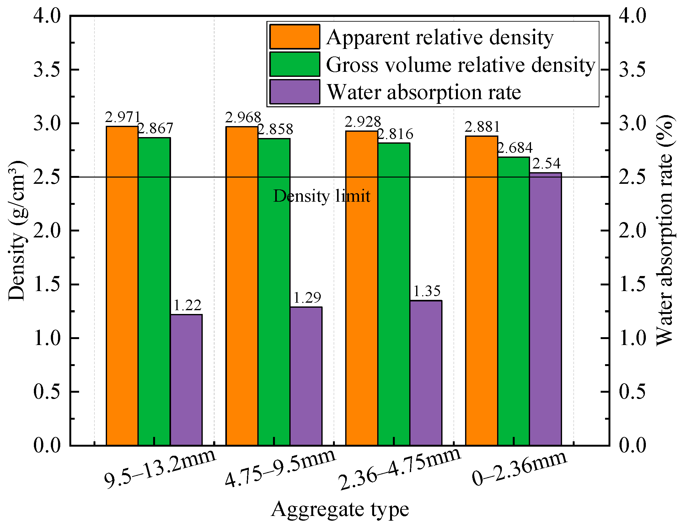
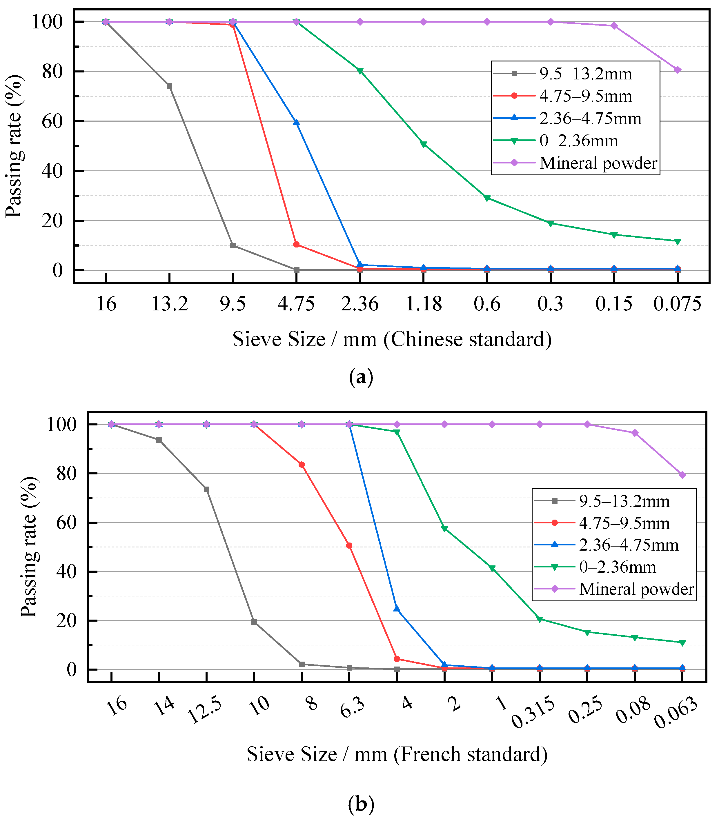
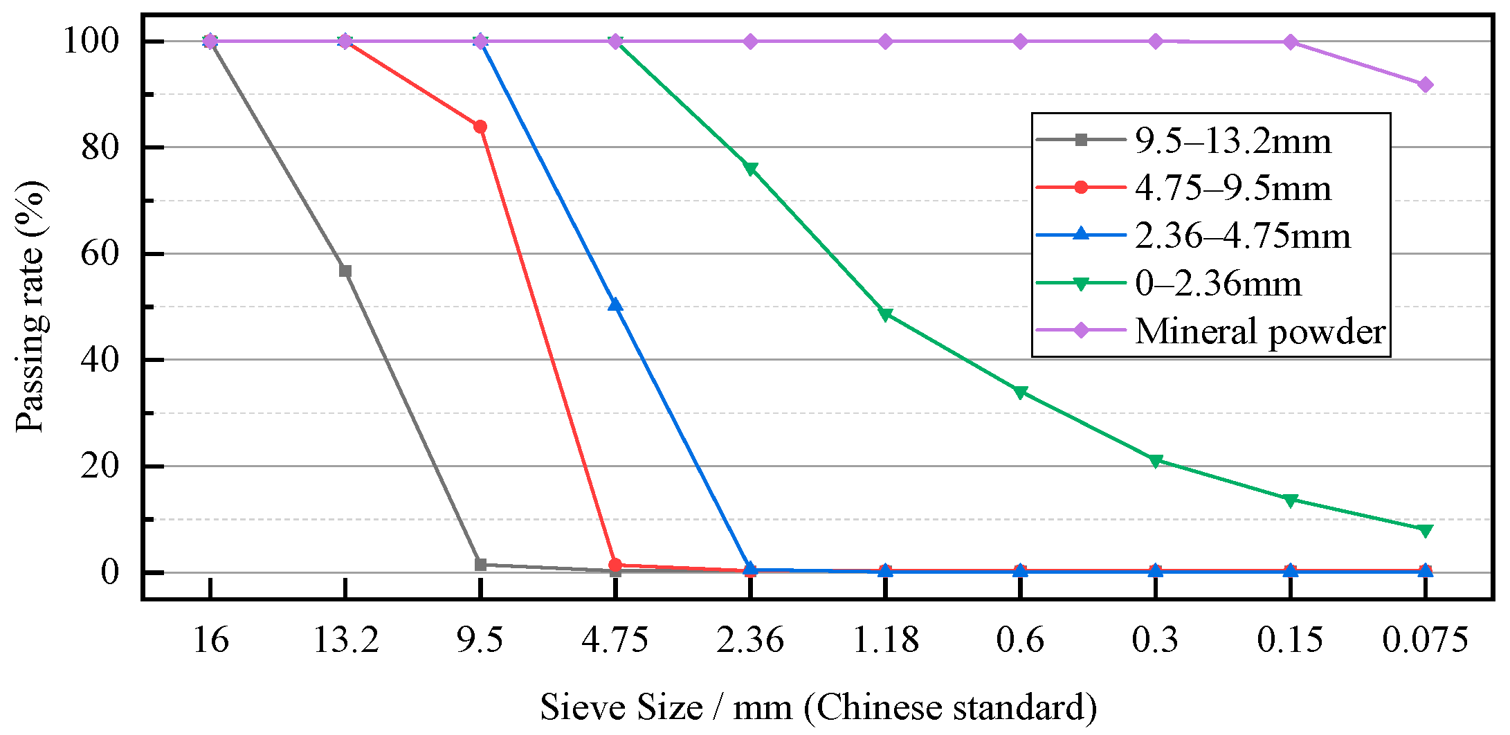
2.2. Aggregates
2.2.1. The Aggregate Used for the Indoor Mix Design
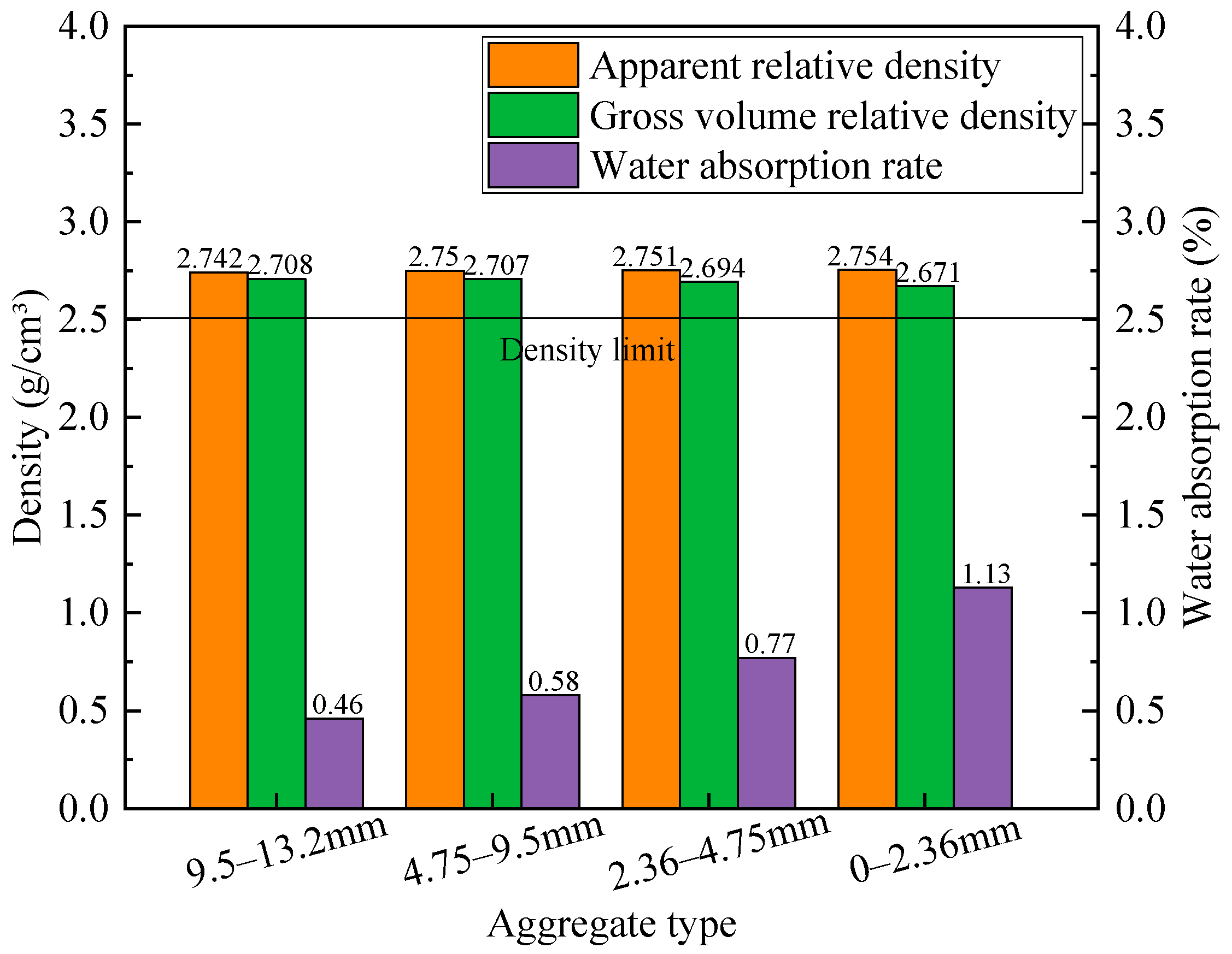
2.2.2. The Aggregates Used for On-Site Mix Design
2.3. Mineral Powder
2.4. Composite High-Modulus Modifier
2.5. Experimental Methods
2.5.1. The Rotational Compaction Method (SGC)
2.5.2. Freeze–Thaw Splitting Test
2.5.3. Rutting Test
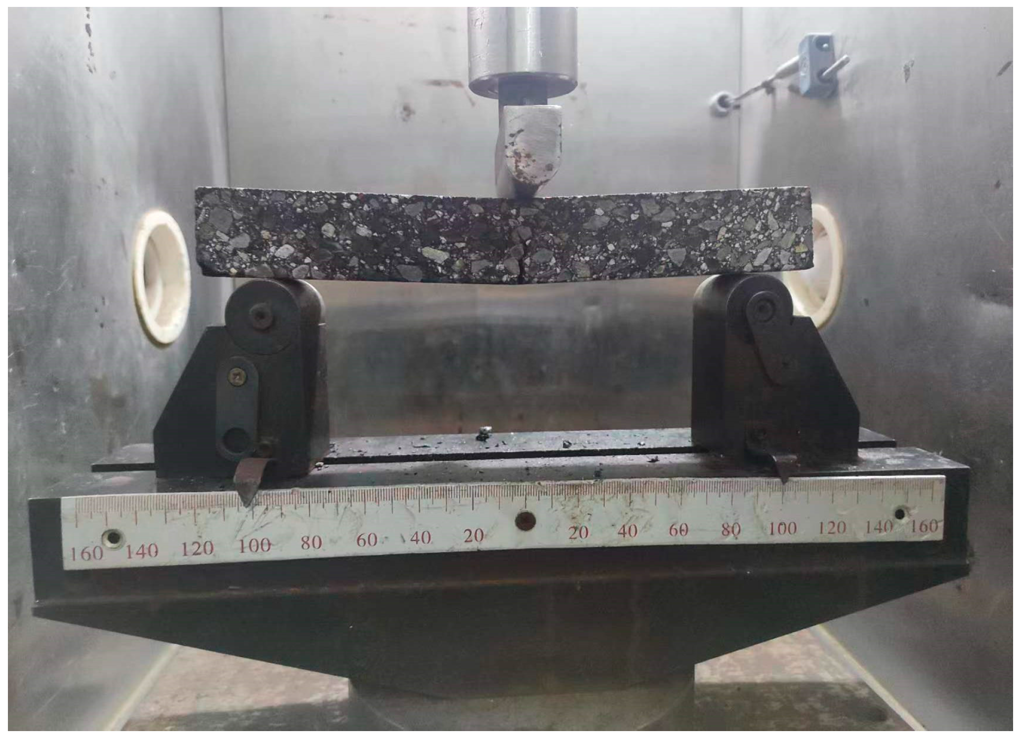
2.5.4. Bending Test
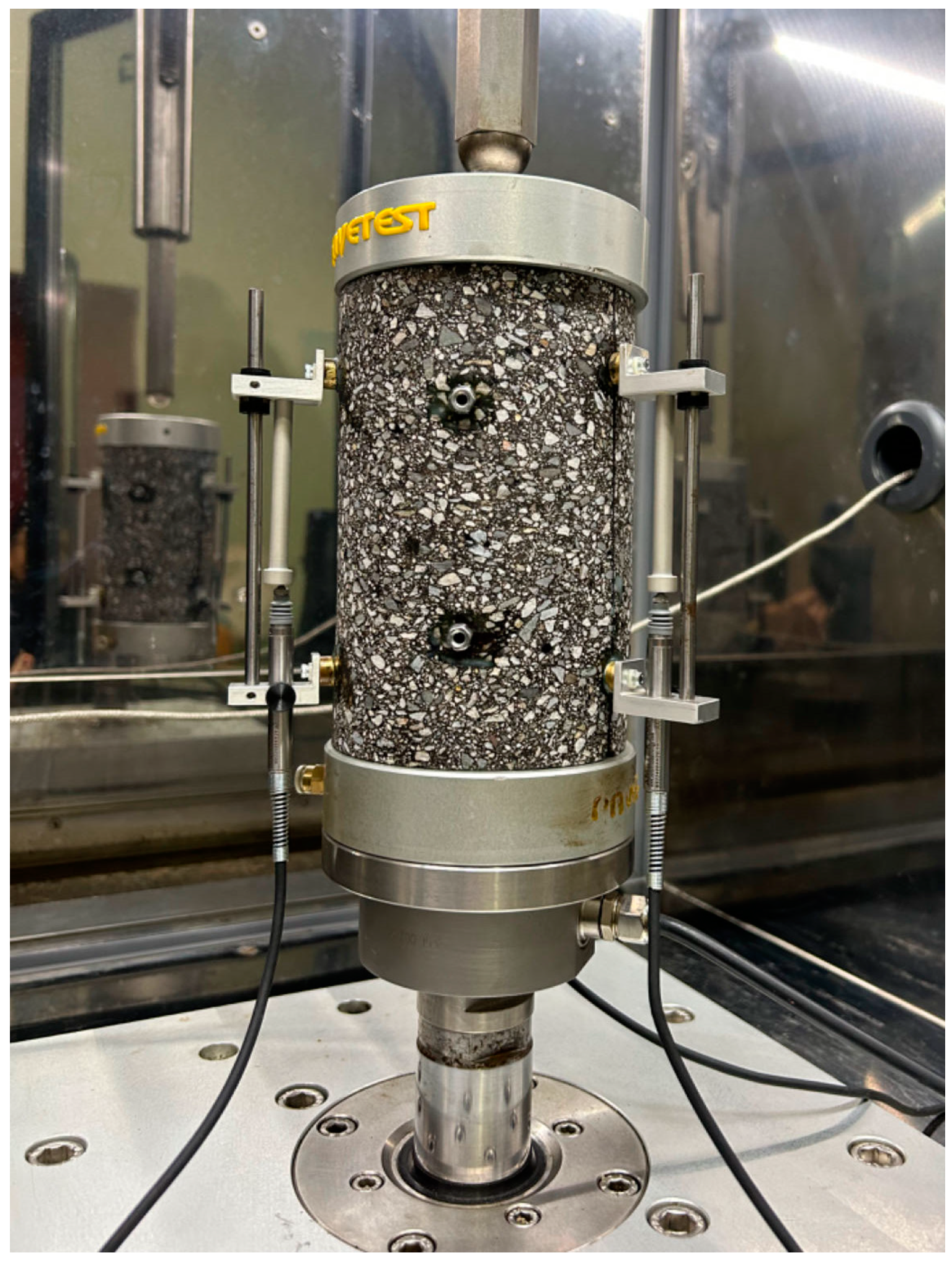
2.5.5. Dynamic Modulus Test
3. Results and Discussion
3.1. Indoor Mix Design
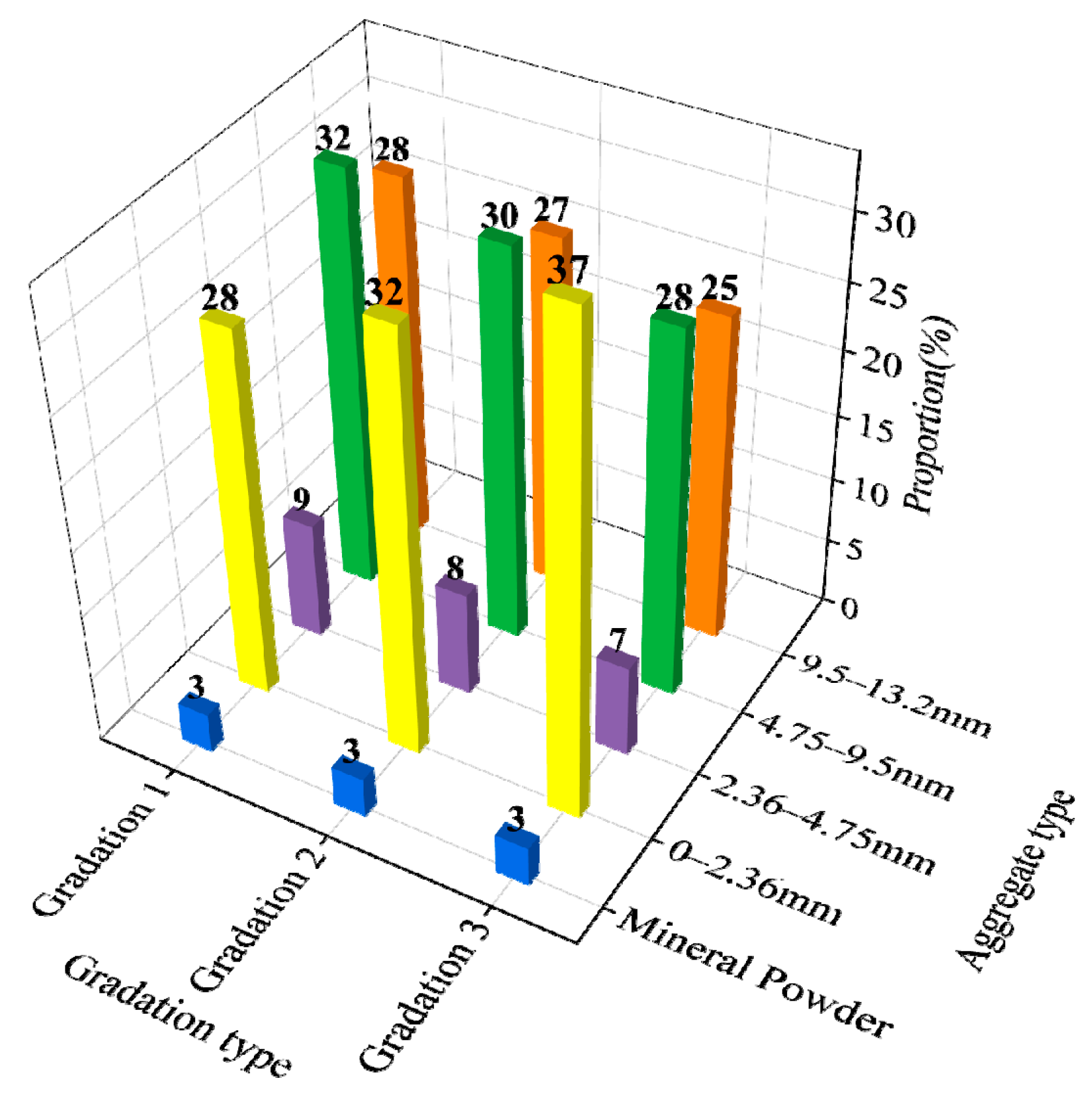
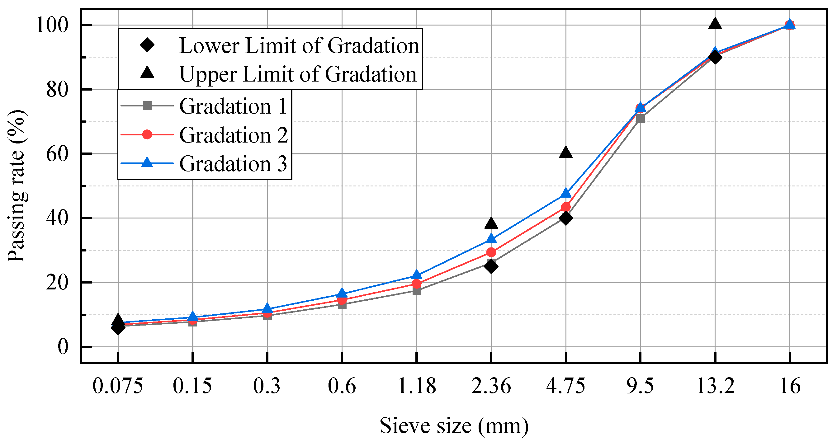
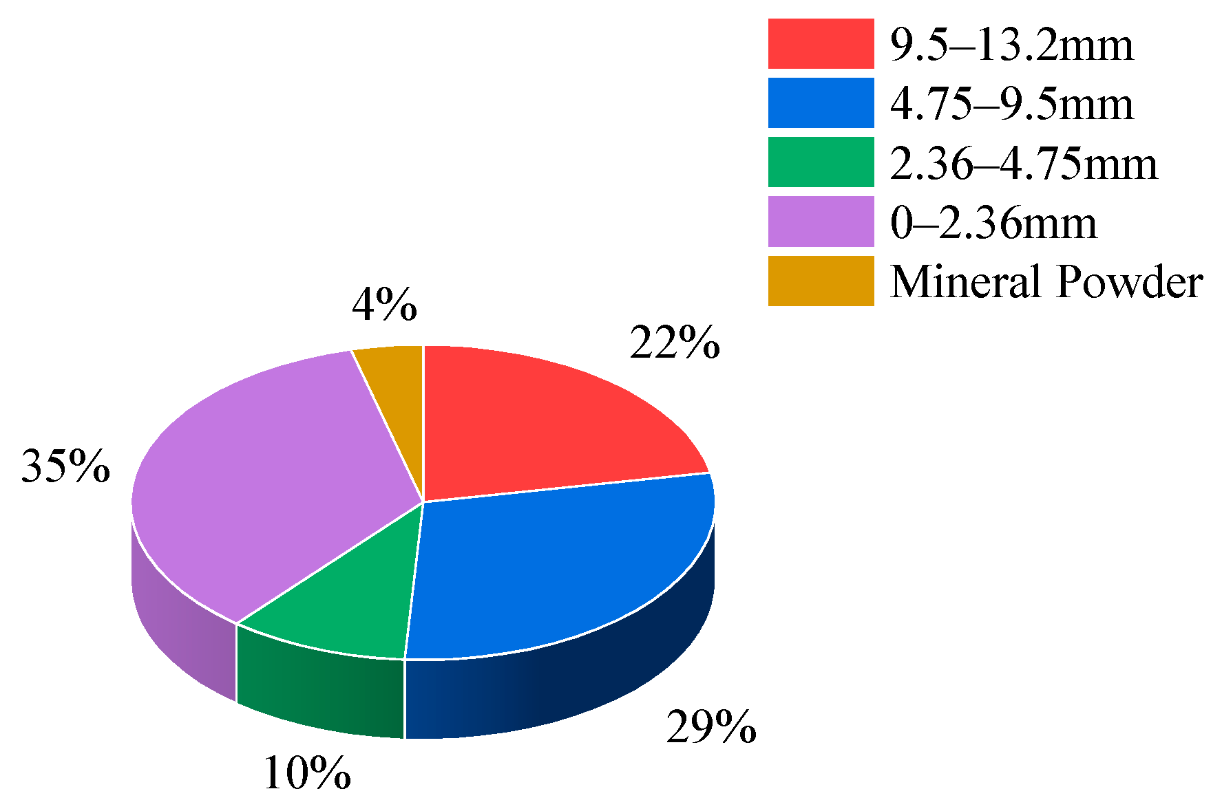
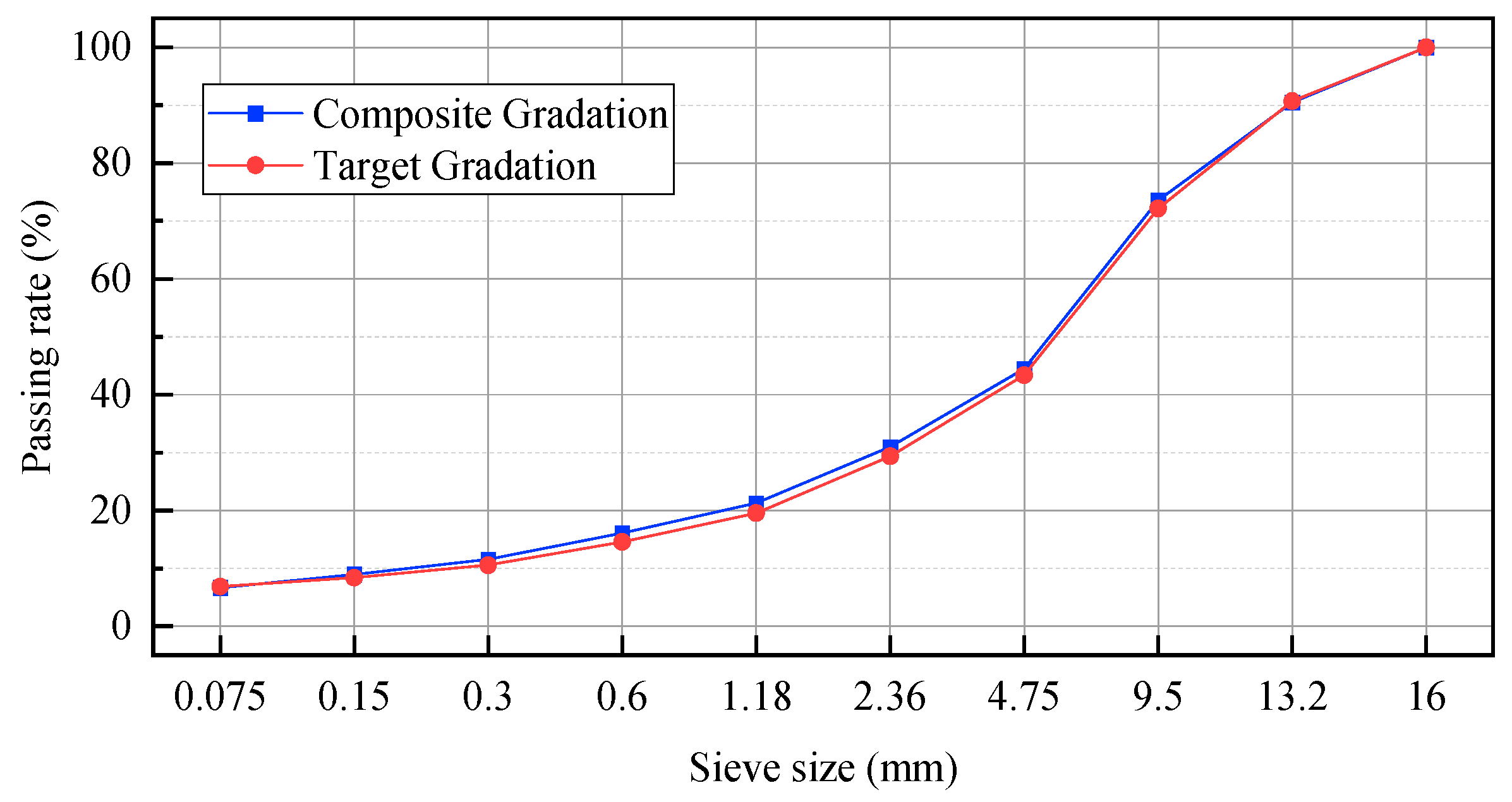
3.1.1. Preliminary Gradation
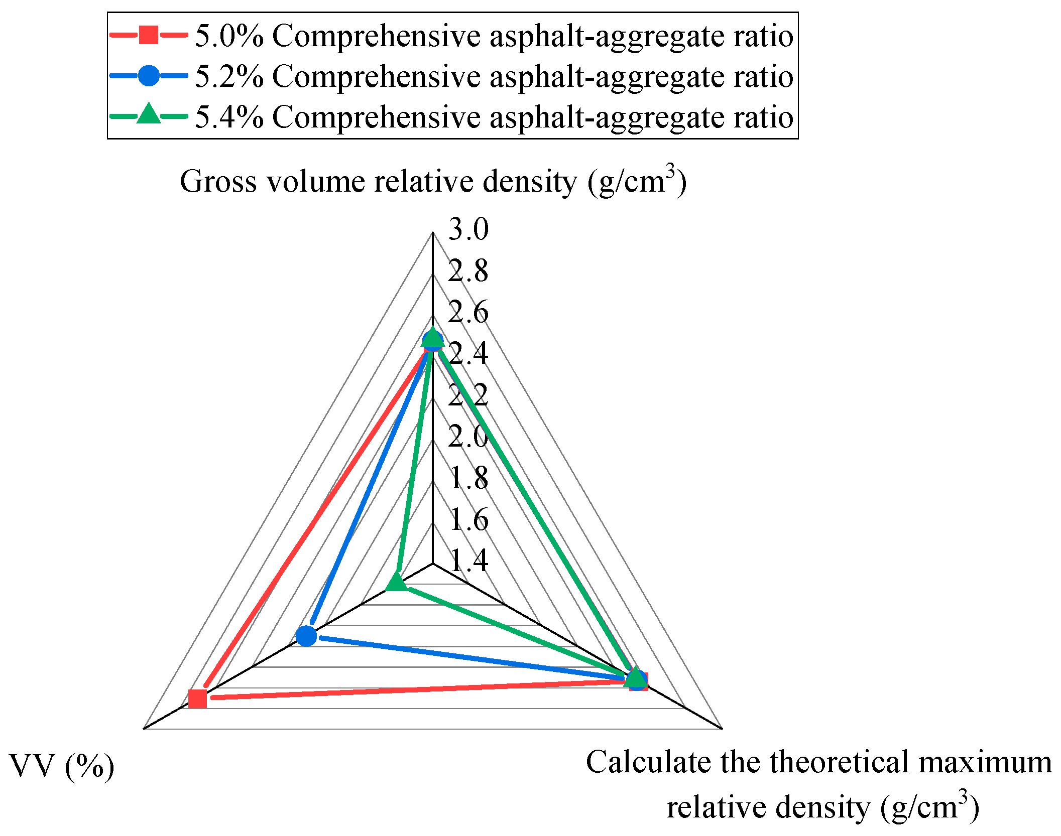
3.1.2. Determination of Asphalt Content
3.1.3. The Verification of the Road Performance Test for Asphalt Mixtures
3.2. On-Site Mix Design
3.2.1. Verification of Raw Material Specifications
3.2.2. Construction Site Gradation Adjustment
3.2.3. Determination of the Optimal Asphalt Content Ratio through On-Site Mix Design
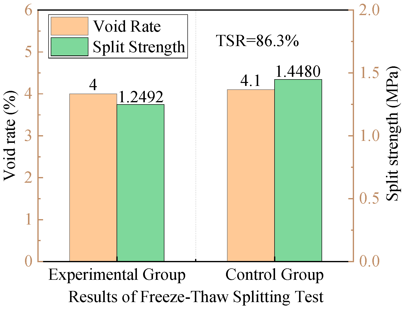
3.2.4. The Water Stability Test of On-Site Mix Design
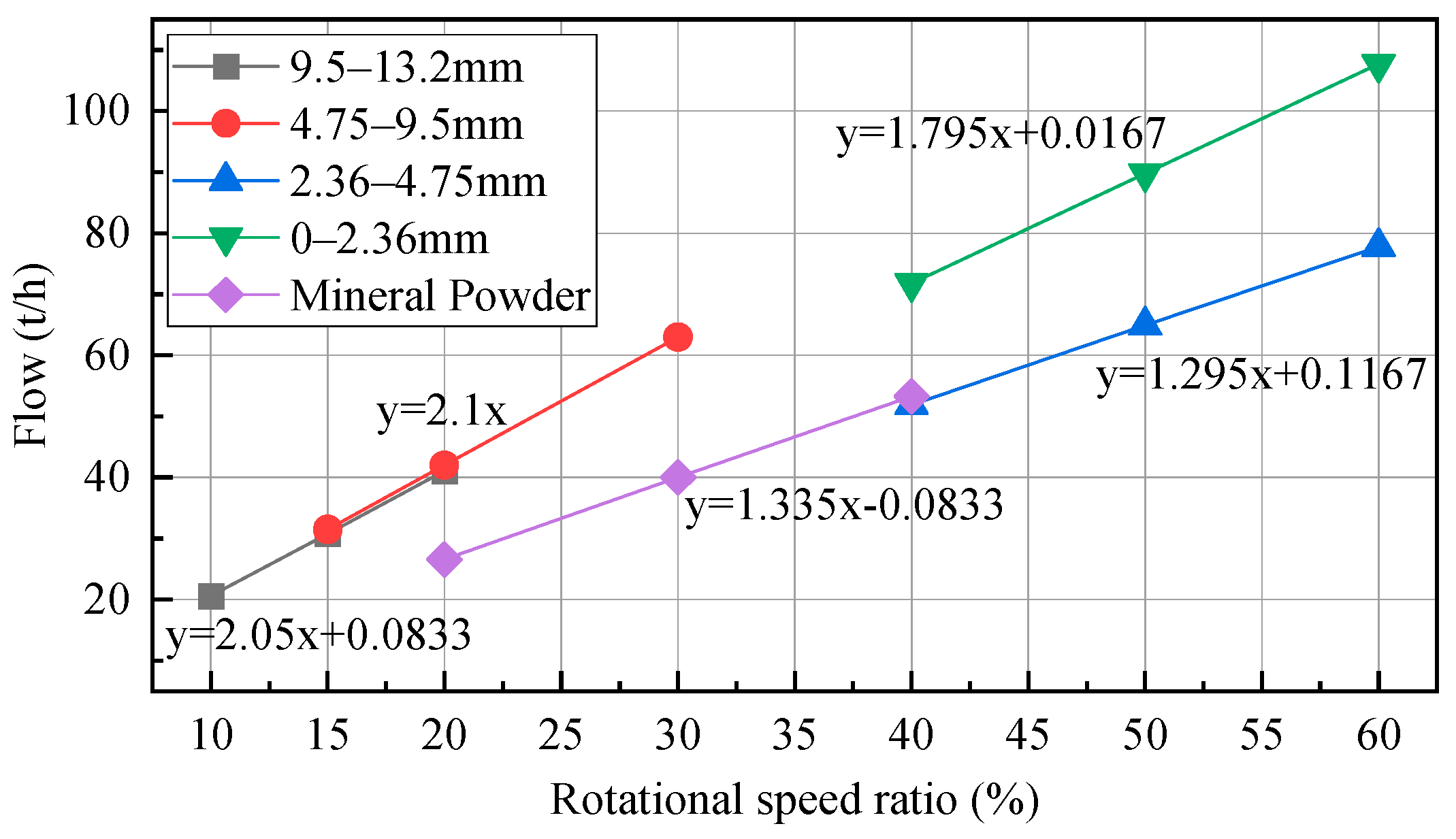
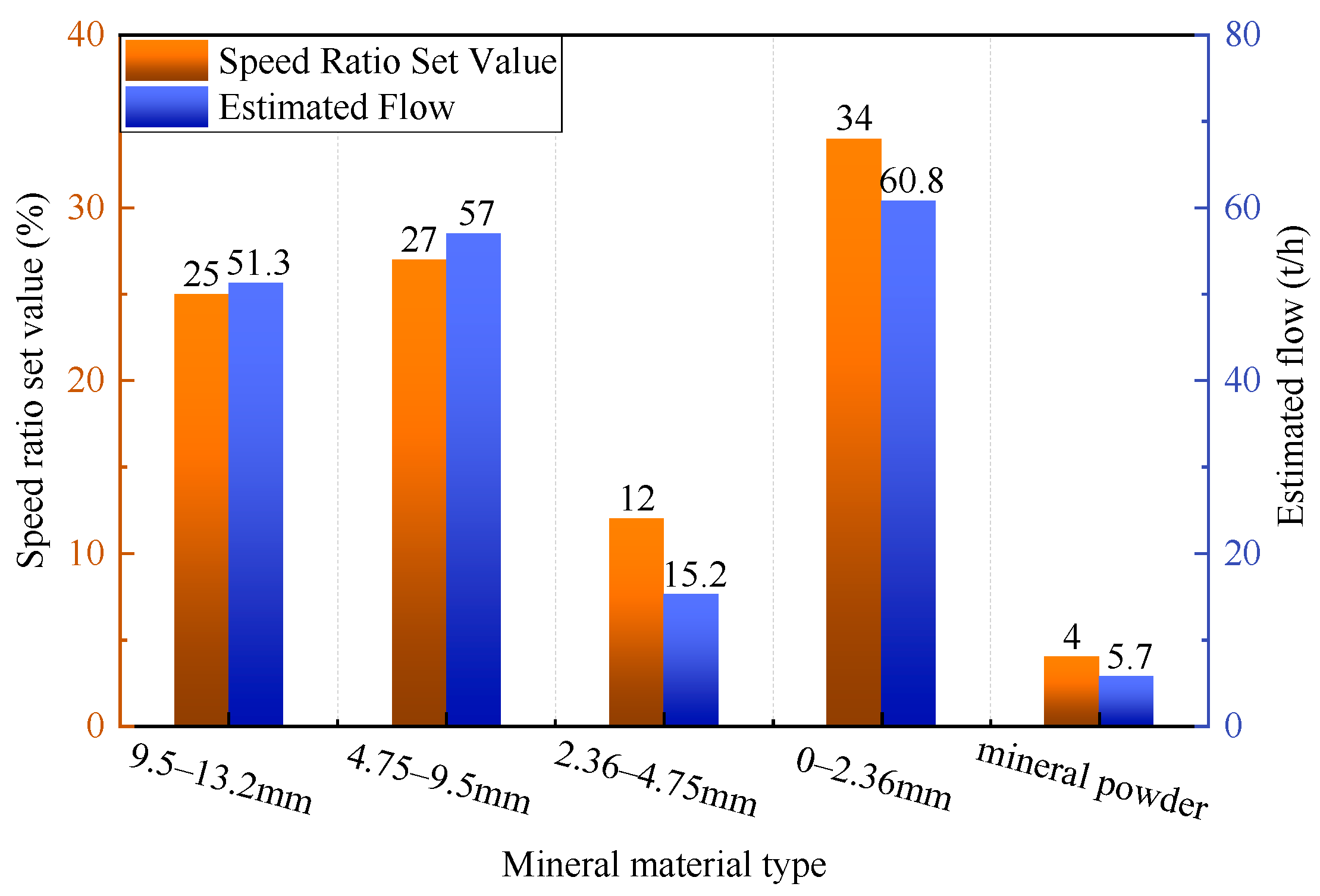
3.2.5. The Cold Material Flow Rate Test in the Mixing Plant
4. Conclusions
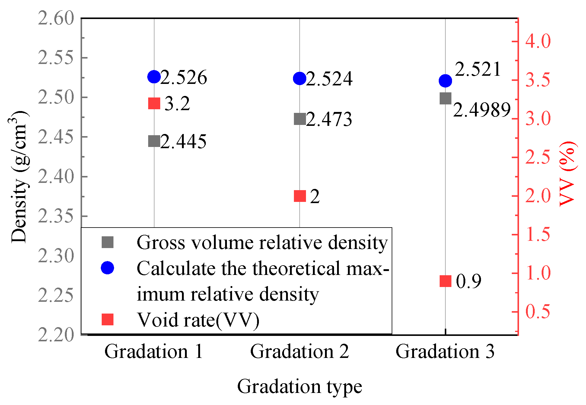
- A laboratory indoor mix design was carried out. The optimal aggregate gradation was determined first. Then, through the rotational compaction method, the void ratio and density of the high-modulus asphalt mixture were tested. The optimum asphalt content ratio for the indoor mix design was determined to be 4.2%, with a 1% dosage of high-modulus modifier. Under these conditions, the void ratio of the high-modulus asphalt mixture specimen was 2.0%, the gross volume relative density was 2.473, and the calculated theoretical maximum relative density was 2.524.
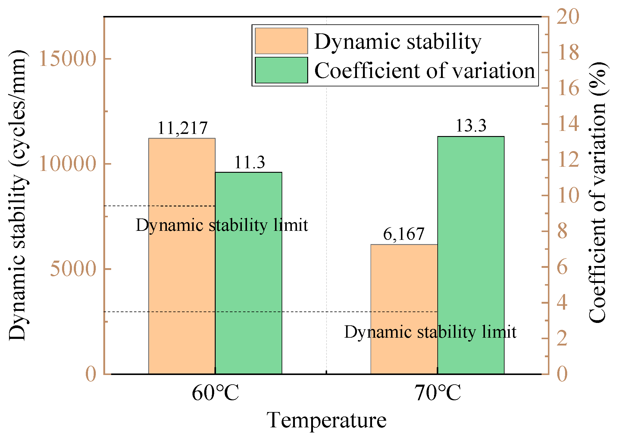
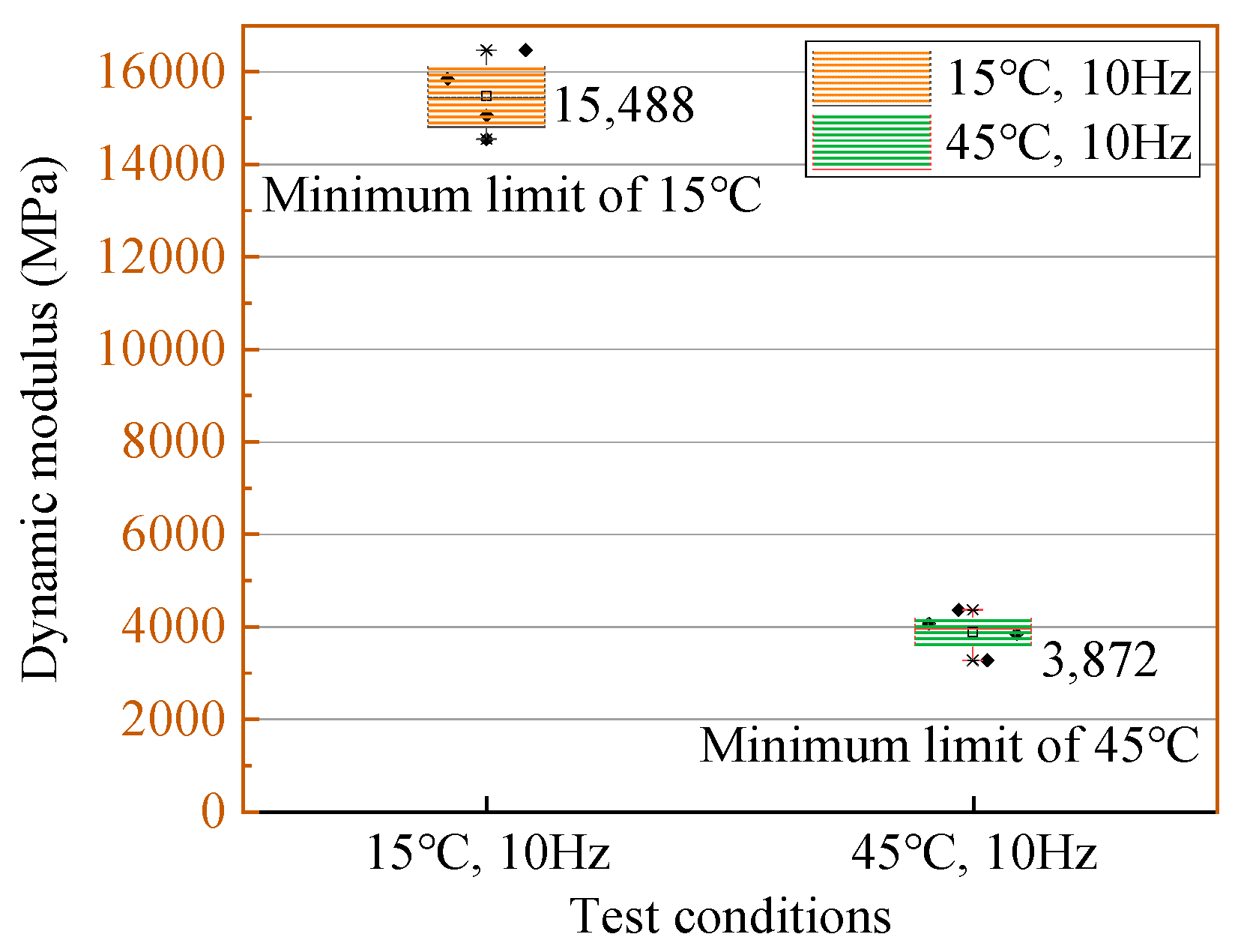
- The performance verification was conducted on the high-modulus asphalt mixture using a 5.2% comprehensive asphalt content ratio, based on the indoor mix design results. The tests included −10 °C beam bending, 60 °C and 70 °C rutting, freeze–thaw splitting, and single-axis compression dynamic modulus tests. The results indicated that the mixture met the requirements for low-temperature performance, high-temperature performance, water stability, and dynamic modulus.
- An on-site mix design was conducted at the construction site. Sieve analysis revealed minor differences in the aggregate between the construction site and indoor design, leading to adjustments in gradation. The optimal asphalt content ratio was determined based on the on-site mix design, which is still 4.2%, with the modifier content remained at 1%. Finally, the water stability was verified, and was found to be in compliance with the requirements.
- The model of the mixing plant at the construction site was investigated, and an assessment of its cold material flow rate was completed. The relationship between the rotation speed of the cold material bins and the corresponding discharge weight of the aggregate was established and adjusted. The rotation speed ratios of the cold material bins were determined for a production rate of 200 t/h in the mixing plant. This effectively reduced the delay and overflow of materials in the mixing plant, thereby reducing the variability of the asphalt mixture aggregate gradation.
Author Contributions
Funding
Institutional Review Board Statement
Informed Consent Statement
Data Availability Statement
Conflicts of Interest
References
- Yan, Y.; Roque, R.; Cocconcelli, C.; Bekoe, M.; Lopp, G. Evaluation of cracking performance for polymer-modified asphalt mixtures with high RAP content. Road Mater. Pavement Des. 2017, 18, 450–470. [Google Scholar] [CrossRef]
- Zeng, G.; Wu, W.; Li, J.; Xu, Q.; Li, X.; Yan, X.; Han, Y.; Wei, J. Comparative Study on Road Performance of Low-Grade Hard Asphalt and Mixture in China and France. Coatings 2022, 12, 270. [Google Scholar] [CrossRef]
- Wang, F. Research on Performance Evaluation System for High Modulus Asphalt Concrete. Master’s Thesis, Chang’an University, Xi’an, China, 2011. [Google Scholar]
- Song, S. Research on High Modulus Asphalt Concrete Pavement. Master’s Thesis, Chang’an University, Xi’an, China, 2014. [Google Scholar]
- Han, C. Design and Application Research of Durable High Modulus Asphalt Mixture Based on Hard Asphalt. Master’s Thesis, Southeast University, Nanjing, China, 2018. [Google Scholar]
- Khiavi, A.K.; Naseri, S. The effect of bitumen types on the performance of high-modulus asphalt mixtures. Petrol. Sci. Technol. 2019, 37, 1223–1230. [Google Scholar] [CrossRef]
- Wielinski, J.C.; Huber, G.A. Evaluation of French High Modulus Asphalt (EME) in Pavement Structural Design (MEPDG). Asph. Paving Technol. 2011, 80, 697–718. [Google Scholar]
- Ma, T.; Ding, X.; Zhang, D.; Huang, X.; Chen, J. Experimental study of recycled asphalt concrete modified by high-modulus agent. Constr. Build. Mater. 2016, 128, 128–135. [Google Scholar] [CrossRef]
- Zou, M. Research on the Application of High Modulus Asphalt Concrete in BRT Special Roads. Master’s Thesis, Changsha University of Science and Technology, Changsha, China, 2021. [Google Scholar]
- Chen, Z. Research on Road Performance of High Modulus Asphalt Mixtures in Wet and Hot Environments. Master’s Thesis, Chongqing Jiaotong University, Chongqing, China, 2014. [Google Scholar]
- Guo, L.; Xu, Q.; Zeng, G.; Wu, W.; Zhou, M.; Yan, X.; Zhang, X.; Wei, J. Comparative Study on Complex Modulus and Dynamic Modulus of High-Modulus Asphalt Mixture. Coatings 2021, 11, 1502. [Google Scholar] [CrossRef]
- Yan, J.; Leng, Z.; Ling, C.; Zhu, J.; Zhou, L. Characterization and comparison of high-modulus asphalt mixtures produced with different methods. Constr. Build. Mater. 2020, 237, 117594. [Google Scholar] [CrossRef]
- Corté, J.F. Development and uses of hard-grade asphalt and of high-modulus asphalt mixes in France. Transp. Res. Circ. 2001, 503, 12–31. [Google Scholar]
- Zhou, J. High Modulus Quantitative Design Theory and Performance Research of Recycled Asphalt Mixture with Large Old Material Content. Doctoral Dissertation, Southeast University, Nanjing, China, 2020. [Google Scholar]
- Wang, C.; Tan, S.; Chen, Q.; Han, J.; Song, L.; Fu, Y. Dynamic Modulus Prediction of a High-Modulus Asphalt Mixture. Adv. Civ. Eng. 2021, 2021, 9944415. [Google Scholar] [CrossRef]
- Wang, X.; Ma, S.; Wei, J. Performance and Design of High Modulus Asphalt Mixture in Different Gradation. In Proceedings of the Transportation Research Congress 2017: Sustainable, Smart, and Resilient Transportation, Beijing, China, 23–25 May 2017; pp. 205–211. [Google Scholar]
- Peng, Y. Development and Application of Special Hard Asphalt for High Modulus Asphalt Mixtures. Master’s Thesis, Chang’an University, Xi’an, China, 2014. [Google Scholar]
- Wu, C.; Jing, B.; Li, X. Performance Evaluation of High-modulus Asphalt Mixture. Adv. Mater. Process. 2011, 311–313, 2138–2141. [Google Scholar] [CrossRef]
- Lu, J. Research on Fatigue Performance of RCA High Modulus Modified Asphalt and Asphalt Mixture. Master’s Thesis, Inner Mongolia Agricultural University, Hohhot, China, 2022. [Google Scholar]
- Xia, Y. Research on the Influence of Different High Modulus Admixtures on the Road Performance of Asphalt Mixtures. Master’s Thesis, Northeast Forestry University, Harbin, China, 2017. [Google Scholar]
- Fang, Z. Research on Plant Mix Hot Recycled High Modulus Asphalt Mixture Technology. Master’s Thesis, Southeast University, Nanjing, China, 2019. [Google Scholar]
- NF P 98~140; Couches d’ Assises: Enrobés à Module Élevé (EME). French Association Française de Normalisation: Saint-Denis, France, 1999.
- Mi, S.; Li, Y.; Zhang, H. Preparation and Characterization of High Modulus Agent Modified Asphalt and Its High Modulus Mixture. Adv. Mater. Sci. Eng. 2022, 2022, 2374241. [Google Scholar] [CrossRef]
- Wang, C.; Zhou, X.; Yuan, H.; Chen, H.; Zhou, L.; Fu, Y. Preparation and performance of UHMWP modified asphalt and its high modulus mixture. Constr. Build. Mater. 2021, 294, 123629. [Google Scholar] [CrossRef]
- Ma, F.; Sha, A.M. Study on Design methods of High Modulus Asphalt Mixtures. In Proceedings of the International Workshop on Energy and Environment in the Development of Sustainable Asphalt Pavements, Proceedings 2010, Xi’an, China, 6–8 June 2010; pp. 212–216. [Google Scholar]
- Wang, X.; Qiu, Y.; Xue, S.; Yang, Y.; Zheng, Y. Study on durability of high-modulus asphalt mixture based on TLA and fibre composite modification technology. Int. J. Pavement Eng. 2018, 19, 930–936. [Google Scholar] [CrossRef]
- Zheng, J. Research on Durable High Modulus Asphalt Pavement Structure. Master’s Thesis, Chongqing Jiaotong University, Chongqing, China, 2013. [Google Scholar]
- Xu, X. Research on Structure and Material Design of Full Thickness High modulus Asphalt Pavement. Master’s Thesis, Chongqing Jiaotong University, Chongqing, China, 2020. [Google Scholar]
- Xie, S. Research on the Road Performance of Basalt Fiber High Modulus Asphalt Mixture. Master’s Thesis, Chongqing Jiaotong University, Chongqing, China, 2018. [Google Scholar]
- Ma, F.; Sha, A.M.; Yang, Q. Study on Road Performances of High Modulus Asphalt Mixtures. In Proceedings of the International Workshop On Energy and Environment in the Development of Sustainable Asphalt Pavements, Proceedings 2010, Xi’an, China, 6–8 June 2010; pp. 426–430. [Google Scholar]
- Sun, X. Design and Economic Benefit Analysis of High Modulus Quantitative Grading for Asphalt Concrete on Heavy Load Pavement. Master’s Thesis, Jilin University, Changchun, China, 2016. [Google Scholar]
- JTG E42–2005; Test Methods of Aggregates for Highway Engineering. Ministry of Communications of the PRC: Beijing, China, 2005.
- JTG E20–2011; Standard Test Methods of Bitumen and Bituminous Mixtures for Highway Engineering. Ministry of Communications of the PRC: Beijing, China, 2011.


| Test Items | Unit | Specified Value | Actual Measurement Results |
|---|---|---|---|
| Relative Density (25 °C) | - | Actual Measurement | 1.034 |
| Needle Penetration (25 °C) | (0.1 mm) | 40–70 | 56 |
| Ductility (5 °C) | (cm) | ≥25 | 31 |
| Softening Point | (°C) | ≥70 | 92.0 |
| Characteristic | Technical Requirement |
|---|---|
| Appearance | Uniform Black Particles |
| Particle Size | ≤8.0 mm |
| Density | 1.0–1.2 g/cm3 |
| Softening Point | 110–140 °C |
| Melting Point | 110–150 °C |
| Melt Mass-Flow Rate (140 °C, 2.16 kg) | ≥50 g/10 min |
| Ash Content | ≤5% |
| Test Parameters | Parameter Values |
|---|---|
| Rotating Compaction Angle | Internal Angle (1.16° ± 0.02°) |
| Number of Rotations | 80 times |
| Rotation Rate | 30 ± 0.5 rev/min |
| Vertical Pressure | 0.6 ± 0.018 MPa |
| Test Piece Diameter | 150 ± 0.1 mm |
| Maximum Load (kN) | Mid-Span Deflection (mm) | Bending Tensile Strength (MPa) | Stiffness Modulus (MPa) | Destructive Strain (με) | Requirement of Strain (με) |
|---|---|---|---|---|---|
| 1.369 | 0.390 | 11.12 | 5438 | 2049 | ≥1800 |
Disclaimer/Publisher’s Note: The statements, opinions and data contained in all publications are solely those of the individual author(s) and contributor(s) and not of MDPI and/or the editor(s). MDPI and/or the editor(s) disclaim responsibility for any injury to people or property resulting from any ideas, methods, instructions or products referred to in the content. |
© 2024 by the authors. Licensee MDPI, Basel, Switzerland. This article is an open access article distributed under the terms and conditions of the Creative Commons Attribution (CC BY) license (https://creativecommons.org/licenses/by/4.0/).
Share and Cite
Li, B.; Liu, Z.; Li, M.; Fei, Y.; Yi, J. Design of High-Modulus Asphalt Concrete for the Middle Layer of Asphalt Pavement. Coatings 2024, 14, 185. https://doi.org/10.3390/coatings14020185
Li B, Liu Z, Li M, Fei Y, Yi J. Design of High-Modulus Asphalt Concrete for the Middle Layer of Asphalt Pavement. Coatings. 2024; 14(2):185. https://doi.org/10.3390/coatings14020185
Chicago/Turabian StyleLi, Bin, Zengxin Liu, Meng Li, Yanhua Fei, and Junyan Yi. 2024. "Design of High-Modulus Asphalt Concrete for the Middle Layer of Asphalt Pavement" Coatings 14, no. 2: 185. https://doi.org/10.3390/coatings14020185
APA StyleLi, B., Liu, Z., Li, M., Fei, Y., & Yi, J. (2024). Design of High-Modulus Asphalt Concrete for the Middle Layer of Asphalt Pavement. Coatings, 14(2), 185. https://doi.org/10.3390/coatings14020185