Abstract
In an electromagnetic launch system, the surface of the aluminum alloy armature is subjected to high-temperature ablation, leading to the generation of significant metal vapor and the initiation of high-energy arcs. This damages the armature structure and can result in a launch failure. Enhancing the ablation resistance of the armature surface is crucial for improving launch efficiency. In this study, a model for the surface modification of an aluminum alloy armature was constructed. The impact of the CoCrNiFeAlx surface-modified material on the resistance to ablation and structural changes of the armature during arc ablation was elucidated through molecular dynamics simulation. Results show that adding a CoCrNiFeAlx fused cladding layer can effectively enhance the material’s high-temperature resistance. The CoCrNiFeAlx fused cladding significantly reduces the depth of arc intrusion. The CoCrNiFeAlx aluminum alloy model exhibits a narrower strain range on the bombarded surface and a more flattened bombardment crater shape. CoCrNiFeAlx fused cladding helps to reduce damage from substrate bombardment. Comparing simulation results indicates that CoCrNiFeAl0.25 performs best in high-temperature resistance and impact strength, making it the most preferred choice. This study elucidates the law of high-entropy alloy arc ablation resistance and its micromechanism in armature surface modification. It provides a theoretical basis and technical support for preparing high-entropy alloy–aluminum alloy-modified armatures with superior ablation resistance performance.
1. Introduction
Under the current complex international situation, China is confronted with pressures and challenges in various areas, including the economy, science and technology, and security. The development of strategic and cutting-edge military technology, as well as the acceleration of military modernization, are important guarantees for China’s peaceful development and national rejuvenation. Electromagnetic launch technology is a significant innovation in artillery launch systems compared to conventional methods. It offers highly controllable, rapid response, substantial kinetic energy, and other notable advantages, making it a disruptive technology suitable for the future complex battlefield environment [1]. Current electromagnetic launch technology mainly includes electromagnetic coils and electromagnetic rails. Among these technologies, electromagnetic rail launch technology can easily achieve precise and controllable speed, breaking through the limitations of traditional gunpowder launch theory. So, it has become the preferred technology for electromagnetic launch systems. And in the actual deployment of an electromagnetic railgun, this technology is the preferred choice [2]. During actual launch, the electromagnetic railgun operates at the megaampere level, with a working time in the millisecond range, and it achieves an exit speed of several thousand meters per second. The armature and track form a sliding electric contact for an ultra-high-speed friction pair [3]. The electrical working conditions are extremely challenging. Under such extreme conditions, a significant amount of metal vapor is generated due to high-temperature erosion on the armature surface. This vapor enters the gap between the armature and rail as the armature exits the chamber, leading to high-energy arc damage to the armature structure. This seriously affects the efficiency and reliability of the electromagnetic launch system [4,5,6]. Therefore, studying methods to modify the armature surface and improve its resistance to ablation is a key issue that needs to be addressed in order to enhance launch efficiency.
Surface modification materials widely used today include high-temperature ceramic materials, carbon fiber-reinforced composites, and refractory metal materials. Among these materials, high-temperature ceramic materials exhibit excellent resistance to oxidation and ablation. However, they have poor thermal shock resistance, are brittle, and are prone to failure under vibration environments, making them unsuitable for the extreme working environment of the armature [7]. Graphene, a single-layer two-dimensional honeycomb structure material with excellent electrical, thermal conductivity, and mechanical properties, is widely utilized as a reinforcing phase in metal matrix composites [8,9]. Song et al. were the first to use molecular dynamics simulation to model single-layer graphene-doped aluminum matrix composites. The results demonstrated that doping with single-layer graphene can significantly enhance the elastic modulus and tensile strength of the aluminum matrix [10]. However, it contains a large number of carbon fibers and carbon interfaces, which are prone to oxidation and ablation under high-temperature aerobic environments. It also has poor bonding characteristics with the matrix, making it prone to slip or even spallation as an armature surface modification material [11]. Refractory metal materials exhibit excellent resistance to oxidation and corrosion. Refractory metal materials exhibit good thermal shock resistance and high-temperature toughness, but they lack sufficient strength and oxidation resistance at high temperatures [12]. The high-entropy alloy material discussed in this article exhibits high strength, hardness, wear resistance, temperature resistance, and corrosion resistance [13]. This makes it a promising material for the surface modification of aluminum alloy armatures to enhance their ablation resistance. Zhang and other researchers produced AlCoCrFeNi high-entropy alloy coatings using laser cladding and examined the microstructure, mechanical properties, and wear behavior of the coatings [14]. Yiku Xu and other researchers applied CoCrFeNiTiAl high-entropy alloy coatings onto AISI1045 steel surfaces to investigate the impact of different aluminum content on the microstructure, phase composition, and wear and corrosion resistance of the coatings. The experimental results indicated that the wear and corrosion resistance of the fusion-clad layer was significantly improved with higher aluminum content [15]. Qiu and other researchers applied high-entropy alloy coatings to steel using a laser cladding. The researchers discovered that the surface microhardness of the high-entropy alloy coatings reached 1102 HV, significantly surpassing the hardness of the base material. This suggests that the laser-clad coatings offered effective protection to the substrate [16,17]. It is evident that many distinguished scholars have conducted thorough research on the characteristics of high entropy alloys. However, previous research has primarily focused on the mechanical properties and applications of high-entropy alloys in civil and industrial fields with limited attention given to their resistance to ablation and potential use in electromagnetic emission. Further research is needed to determine whether high-entropy alloy materials maintain good performance under arc erosion and to investigate the micromechanisms of using them as coating materials to protect armatures under extreme conditions.
In addition, previous studies heavily relied on numerous experiments to gather data, which was time-consuming, labor-intensive, and hindered efficiency improvements. In this paper, we utilized molecular dynamics simulation to construct a model of pure aluminum alloy and an armature model for surface modification of aluminum alloy-high entropy alloy. We recorded the temperature and metal vapor changes in the surface layer during high-temperature impact for each model. We investigated the influence of aluminum content on ablation resistance performance and analyzed the evolution of microstructure through the depth of intrusion of bombarded aluminum spheres, surface atomic strain morphology, and substrate damage degree. This allowed us to study the micromechanisms of how high-entropy alloys enhance the ablative corrosion resistance of aluminum matrix composites. We propose an optimal thickness for the high-entropy alloy overlay film and a suitable aluminum mass fraction in the high-entropy alloy through a comprehensive comparison of each model. This method can provide data for future experiments, minimize redundant experiments, and shorten the research cycle.
2. Microscopic Model and Simulation Process of Modified Armature Subjected to Arc Erosion
2.1. Establishing the Model for Arc Erosion of High-Entropy Alloy-Modified Aluminum Alloy Armature
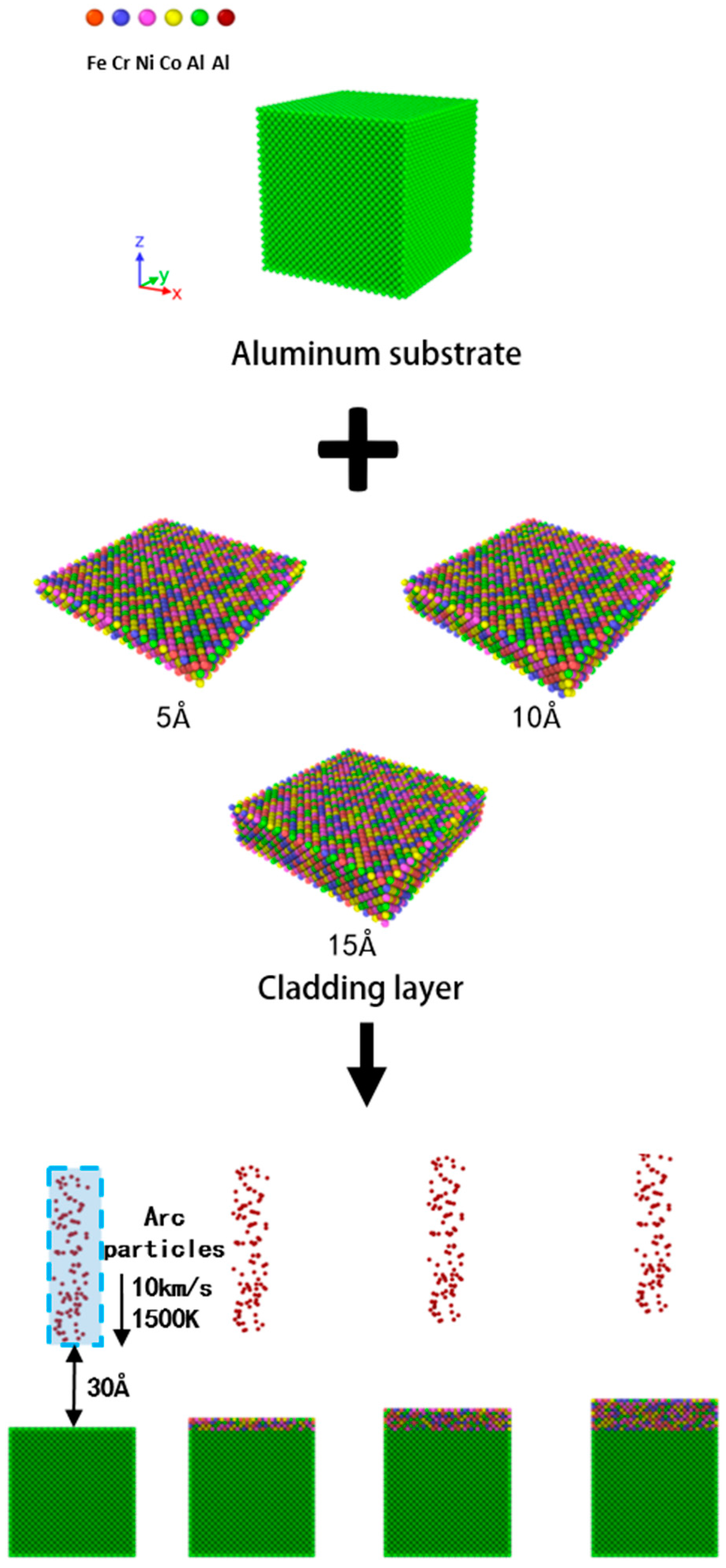
Many scholars have explained the mechanism of armature erosion during electromagnetic emission. Parks proposed the melting wave mechanism [18], followed by James et al. [19], who proposed the “magnetic saw effect” and linked it to the melting wave mechanism. Scholars have also proposed the mechanism of surface high-speed wear [20]. These mechanisms explain how the transition from solid contact to arc contact occurs between the armature and the guide rail. The main reason for triggering the muzzle arc is the sudden change in the gap between the armature and the rail when the armature exits the chamber. The metal material on the armature surface melts, splashes, and even vaporizes under the high temperature generated by frictional heat and Joule heat, causing a large amount of metal vapor to enter the gap and trigger a high-energy arc. The metal atoms in the arc, after being ionized by electron collision emitted by the cathode, accelerate through the space charge sheath near the cathode surface and collide with the cathode surface, resulting in material quality loss [21,22]. As shown in Figure 1, the damage mechanism of the arc on the material is simplified as a beam of aluminum atoms with additional high temperature and velocity bombarding the surface of the material. The necessary simplification is made as follows:
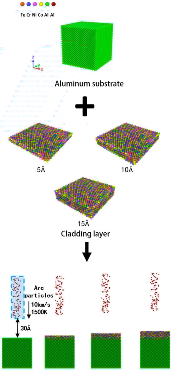
Figure 1.
Schematic diagram of the CoCrNiFeAlx-Al model subjected to arc erosion.
(1) This approach does not account for gas atom ion bombardment of the material, the riffled arc from constant armature movement will not occur in the same stable ablation area, and metal vapor movement accounts for most of the metal providing ionized atoms to maintain the combustion arc.
(2) The primary ionized metal atoms in the metal vapor are set as aluminum atoms. In high-entropy alloy (CoCrNiFeAl)–aluminum alloy materials, the arc tends to occur on the aluminum phase due to its lower escape work and easier electron emission during arc ablation compared to other elements.
(3) The simulation focuses on particle–material interaction during riffled arc ablation, so the riffled arc is simulated by a set of aluminum atoms, which are bombarded by the model at high temperatures. The material damage from the muzzle arc results from the arc’s great thermal energy and high-speed charged particles’ kinetic energy, so a simplified muzzle arc ablation model is set up as a combination of high temperature and high momentum in molecular dynamics simulations [23].
(4) The basic structure of the arc ablation model for the high-entropy alloy-modified aluminum alloy armature is shown in Figure 1. The high-entropy alloy cladding layer of the armature model is uniformly distributed parallel to the upper surface.
2.2. Potential Function Setup
In this study, the large-scale atomic/molecular massively parallel simulator LAMMPS [24] was used to perform molecular dynamics simulations of aluminum alloys and CoCrNiFeAlx-Al materials. Since the classical molecular dynamics simulator LAMMPS was released as an open source code in 2004, it has become a widely used tool for particle-based modeling of materials at length scales ranging from atomic to mesoscale to continuum. LAMMPS is used in our work because it provides a wide variety of particle interaction models for different materials, and it gives us control over simulation details either via the input script or by adding code for new interatomic potentials, constraints, diagnostics, or other features needed for their models. Potential functions can describe atom and molecule interactions in molecular dynamics and simulate material properties in reality. Since conventional pair potentials are unsuitable for describing atomic interactions in extreme operating environments, the electron cloud density-dependent EAM (embedded atom method) potential function is chosen to ensure simulation reliability [25]. The total energy is expressed as shown below:
where F is the energy to embed an atom in site i with electron density , α and β are elemental type subscripts for atoms I and J, i, j refer to different sites where atoms are located, and is the pairwise potential between atoms i, j separated by sites.
The EAM potentials of monatomic elements are invariant to transformations that add or subtract linear terms of electron density from the embedded energy functional, provided their pairing terms are appropriately adjusted. Thus, many single-atom EAM functions developed by different authors may appear different but are mathematically equivalent when transformed. However, when combined to study alloys, this additional freedom of elemental potentials affects predicted alloy properties. This means single-atom potentials cannot simply be used to model alloys unless normalized to a unique state. The alloy EAM potential database developed by Zhou is versatile enough to enable alloy-normalized elemental potential generation for up to 16 metals (Cu, Ag, Au, Ni, Pd, Pt, Al, Pb, Fe, Mo, Ta, W, Mg, Co, Ti and Zr) [26,27]. Therefore, in this paper, molecular dynamics simulations are carried out using multi-principal alloy groups and EAM potential functions generated on the basis of this database.
2.3. Simulation Condition Settings
The BFDH calculation in MS software shows that the (110) crystal plane of aluminum alloy is the most probable growth plane and possesses the fastest growth rate compared to other crystal planes. Therefore, an aluminum alloy substrate model was constructed using MS software with three directions of substrate edge lengths of 81 Å, 81 Å, and 60.75 Å, and an atomic number of 24,000. The use of surface modification techniques such as laser additive will result in the diffusion of substrate elements into the surface cladding layer, and therefore, in order to investigate the effect of different atomic percentage contents of aluminum on the ablation-resistant properties of the high-entropy alloy material, the model CoCrNiFeAlx (x = 0, 0.25, 0.5, 0.75, 1.0) atomic percentage contents were set as 0 at%, 6 at%, 12 at%, 16 at%, 20 at%, respectively. Meanwhile, in order to investigate the effect of the thickness of the fused cladding layer on the ablation resistance of the armature, high-entropy alloy-fused cladding layers with different thicknesses of 5 Å, 10 Å and 15 Å were designed. The CoCrNiFeAlx -aluminum alloy model is shown in Figure 1 after adding the high-entropy alloy fusion cladding layer on top of the aluminum alloy matrix using LAMMPS.
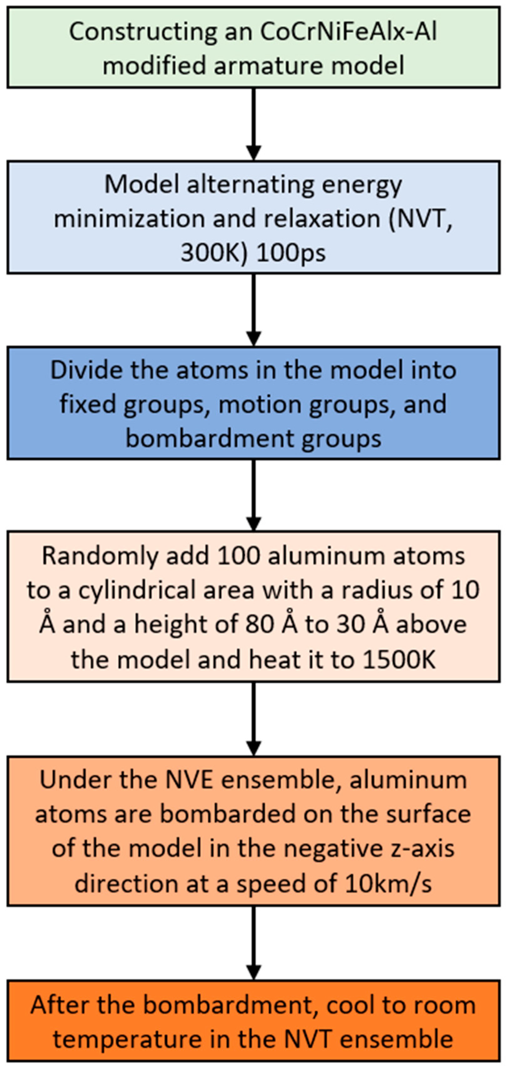
A brief flowchart of the simulation is shown in Figure 2. The x, y directions of the model are set as periodic boundary conditions, while the z direction is set as a contraction boundary condition. The model was initially subjected to energy minimization. Then, it was relaxed under the NVT regime at room temperature (300 K) for 200 ps to optimize the structure and reach equilibrium. The pre-processed aluminum alloy and high-entropy alloy–aluminum alloy models were exported for use as initial models in subsequent simulations. The atoms of the model were divided into groups. The two lowest layers of atoms were fixed to prevent model movement, while the remaining atoms were set as moving layers. To simulate the high momentum and high temperature caused by electroablation, 100 aluminum atoms were randomly added to a cylindrical region with radius 10 Å and height 80 Å, which were centered 30 Å above the model. These aluminum atoms were heated to 1500 K in 1 ps under the NVT system and then switched to the NVE system. This caused the aluminum atoms to bombard the model in the negative z-axis direction at 10 km/s [28].
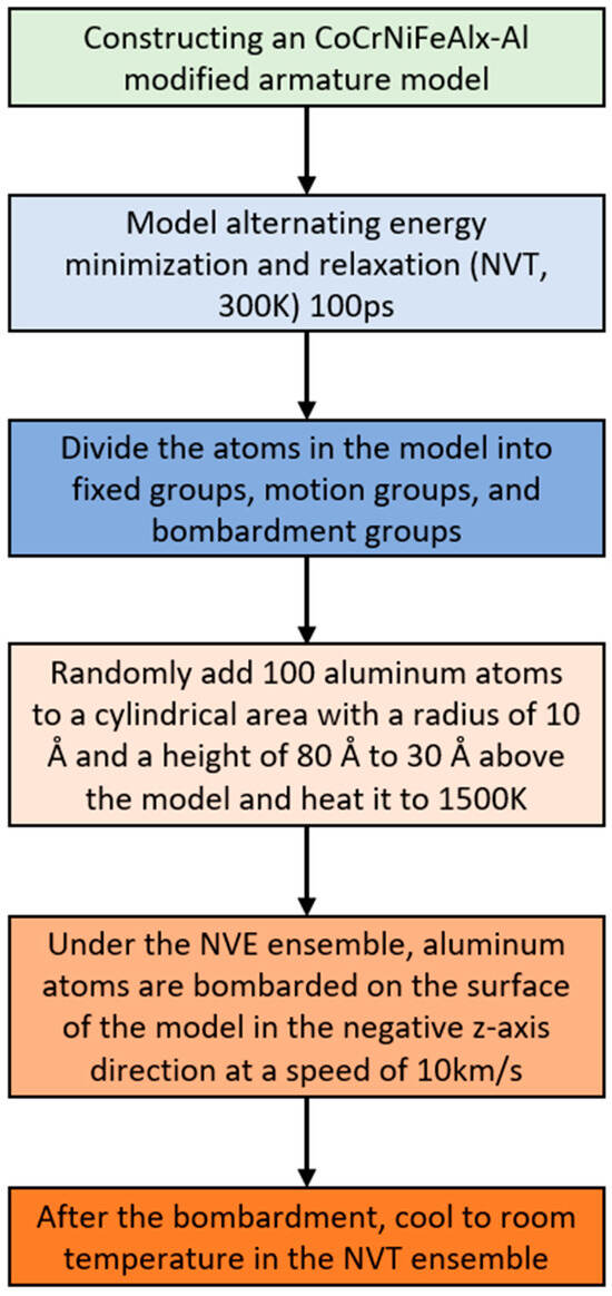
Figure 2.
Simulation flowchart.
We constructed high-entropy alloy–aluminum alloy models with different atomic percentage contents to test the effect of aluminum element content changes on performance. For high-entropy alloy–aluminum alloy models with different cladding layer thicknesses, we used the same bombardment velocity to test the effect of cladding layer thickness on performance. After bombardment, we continued the simulation under the NVE ensemble for a total of 10 ps to promote energy transfer. Then, we cooled the model temperature to room temperature of 300 K under the NVT ensemble to stabilize the system. Then, we observed the simulation results using the visualization software Ovito [29].
3. Material Surface Temperature and Thermodynamic Parameters Change Rule
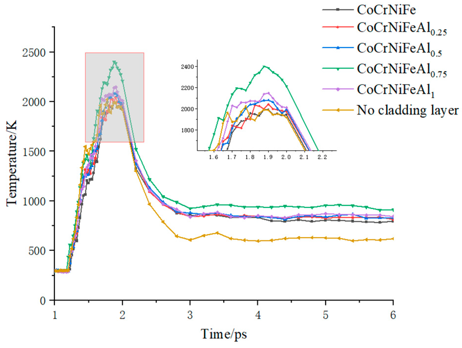
In the mechanism of electromagnetic orbit arc triggering, material melting caused by high temperature is a very important factor in triggering the arc, so improving the material’s high-temperature resistance is crucial. We set atoms within 25 Å from the top surface to the bottom of the substrate model as the temperature measurement layer and studied the temperature changes in areas where aluminum alloy and high-entropy alloy–aluminum alloy models are greatly affected by bombardment. By analyzing Figure 3 and Figure 4, it is evident that the calculated melting point of the CoCrFeNi HEA is approximately 1700 K, which aligns excellently with the experimentally reported value of 1693 K [30]. This result demonstrates that the EAM potential function we utilized effectively captures the interatomic interactions among Co, Cr, Fe, Ni, and Al atoms. Figure 3 shows the temperature variation of the temperature measurement layer over time in a high-entropy alloy–aluminum alloy model with different aluminum element contents in the cladding layer under the action of high-temperature and high-speed aluminum atomic beam bombardment. Table 1 lists the peak temperatures of each model’s temperature measurement layer, with CoCrNiFeAl0.75 having the highest peak temperature, which is 2401 K. The peak temperatures of CoCrNiFeAl, CoCrNiFeAl0.5, CoCrNiFeAl0.25, and CoCrNiFe models are 10.58%, 13.37%, 14.95%, and 17.08% lower than those of CoCrNiFeAl0.75, respectively. The data in the chart show that adding a cladding layer reduces the thermal conductivity of the armature, resulting in a generally higher surface temperature of the coated modified armature compared to the uncoated armature. This is because the chaotic and disordered atomic arrangement in the high-entropy alloy cladding layer increases the scattering probability of phonons, reduces the average free path of phonons, limits their heat transfer function, and leads to a decrease in thermal conductivity [31]. However, the decrease in thermal conductivity is acceptable compared to the improvement in high-temperature performance brought about by adding a cladding layer.
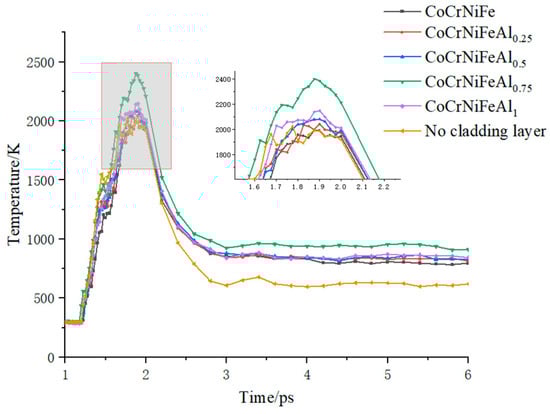
Figure 3.
Surface temperature of CoCrNiFeAlx-Al model.
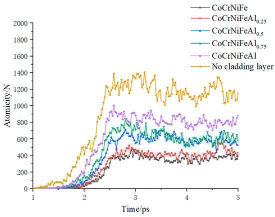
Figure 4.
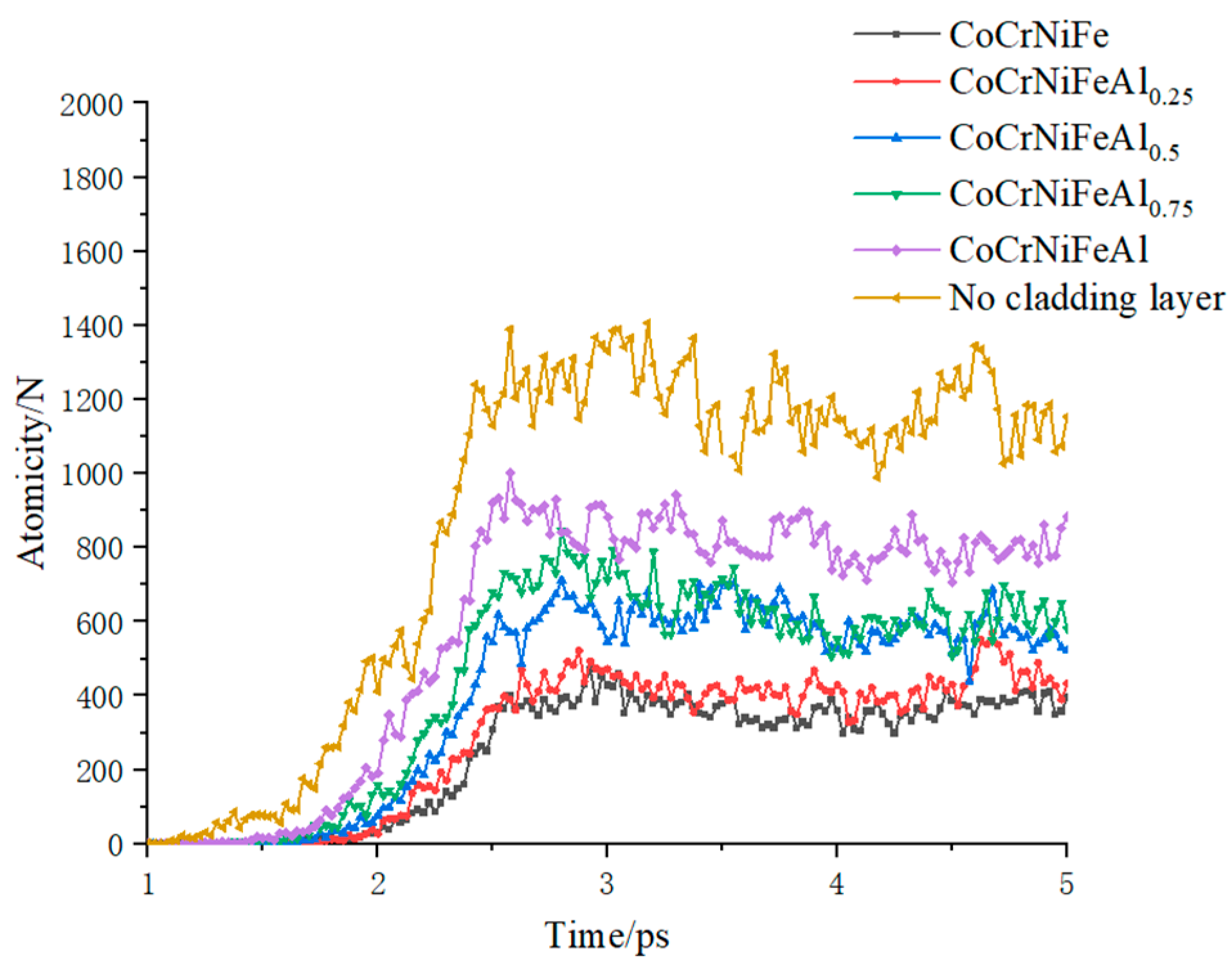
Changes in the total number of atoms in the vacuum layer of the CoCrNiFeAlx-Al model over time.

Table 1.
Peak temperature of CoCrNiFeAlx-Al model.
Figure 4 shows the variation in number of atoms vaporized into the vacuum layer for different high-entropy alloy–aluminum alloy systems under high-temperature, high-speed aluminum atomic beam bombardment. Among them, the uncoated armature model is the first to gasify and has the most severe gasification, because the coating has little effect on temperature rise, and aluminum has low latent heat of evaporation, so it gasifies first. Secondly, the atoms of all elements in the system of metal monolithic or traditional alloys are in the same energy state, and when the energy of surface atoms is affected by bombardment and rises, the directional movement of elemental atoms diffuses relatively fast due to the small lattice distortion existing in metal monolithic or traditional alloys. The diffusion rate of moving elemental atoms is relatively fast. Coupled with the high thermal conductivity of aluminum, the heat generated by bombardment not only causes aluminum atoms at the bombardment point to gasify into the vacuum layer but also spreads rapidly, leading to the successive gasification of aluminum atoms around the bombardment point. The degree of vaporization of the coated armature is significantly lower than that of the uncoated armature. This is because the CoCrNiFeAl alloy is an infinite solid solution formed by mixing cobalt–chromium–nickel dominant elements. It inherits the higher boiling point of these elements and their excellent high-temperature resistance. The alloy also exhibits the cocktail effect on performance. On the other hand, the energy required for the gasification of different elemental atoms in CoCrNiFeAl alloy differs. This makes the atoms of different elements interact with each other. At the same time, the low thermal conductivity of the high-entropy alloy impedes heat transfer between different elemental groups. Therefore, the high-entropy alloy system has excellent high-temperature stability. At similar temperatures, fewer atoms are gasified, and the gasification area is more concentrated for the high-entropy alloy.
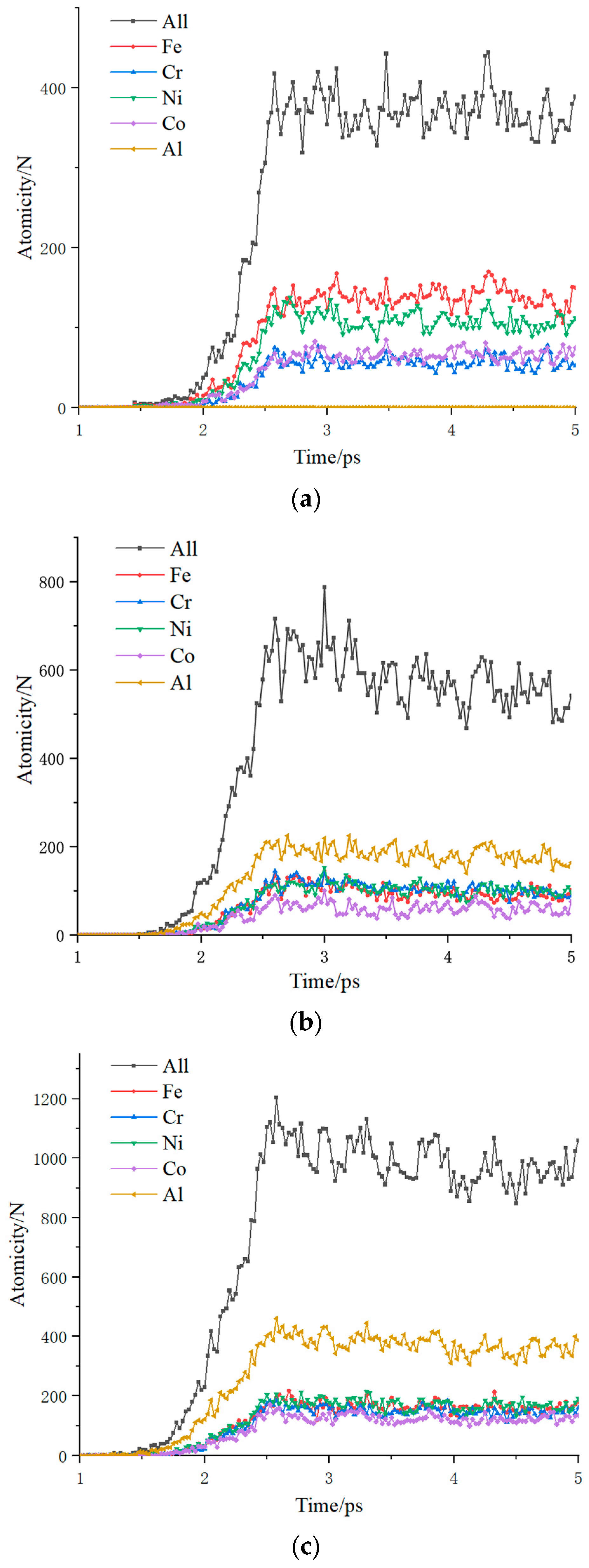
Observing Figure 4, it can also be found that the degree of vaporization of the laminated armature increases with the rise of the aluminum elemental content. To further investigate the influence of the aluminum elemental content on the high-temperature resistance of high-entropy alloy materials, Figure 5 demonstrates the change in the number of atoms of each element in the vacuum layer over time. It can be seen that more and more aluminum atoms are evaporated with the increase in the aluminum elemental content, which is the main reason for the rise of the total number of vaporized atoms. The number of vaporized atoms of other types did not decrease due to the decrease in the ratio, because in high-entropy alloys, multiple elements tend to occupy randomly. When the atoms in the equilibrium position have a high enough energy to cross the energy barrier, they will jump over the energy barrier and achieve the atomic leap. The migration of atoms needs to overcome not only the migration energy of the dot matrix but also the formation of near-side vacancy energy. The latent heat of evaporation of all types of elements is different. Aluminum atoms, due to the low latent heat of evaporation, break free from the bondage and evaporate in large quantities, making the crystal lattice produce gaps and weakening the crystal lattice distortion effect produced by the pinning effect. This makes other elements more likely to be vaporized into the vacuum layer.
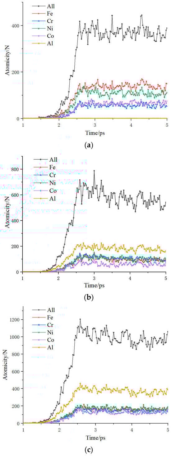
Figure 5.
Changes in atomic numbers of various elements in the vacuum layer over time. (a) CoCrNiFe-coated armature. (b) CoCrNiFeAl0.5-coated armature. (c) CoCrNiFeAl-coated armature.
In summary, CoCrNiFeAl cladding can effectively improve the material’s high-temperature resistance with higher Al content in the fused cladding layer worsening volatilization. Considering reduced metal vapor in air, matrix Al should minimally intrude the surface fused cladding during high-entropy alloy armature preparation, using a low-dilution surface modification method.
4. Evolution of the Microstructure of the Material
4.1. Depth of Bombardment Intrusion
The surface morphology of materials is an important consideration for evaluating the degree of arc erosion. By comparing the maximum intrusion distance of aluminum atoms during bombardment, the aluminum alloy and CoCrNiFeAlx-Al systems were evaluated. The intrusion distance was taken as the distance between the deepest intruding aluminum atom and the model surface (as shown in Figure 6).

Figure 6.
Intrusion depth of the CoCrNiFeAlx-Al model.
Table 2 records the maximum intrusion depths of the pure aluminum alloy armature model and CoCrNiFeAlx-coated models with different Al contents at a bombardment speed of 10 km/s. The pure aluminum alloy model has the largest bombardment intrusion depth of 31.54 Å. All CoCrNiFeAlx–aluminum alloy models have smaller bombardment intrusion depths than the uncoated aluminum alloy armature: reduced by about 42% for the 5 Å fused cladding thickness model, 68% for the 10 Å model, and 70% for the 15 Å model.
Table 2.
Maximum intrusion depth of the CoCrNiFeAlx-Al model.
A comparison of the data with Al shows that the surface modification of high-entropy alloys helps reduce the depth of intrusion of bombarded aluminum atoms. The reason is that the atoms of each element in the aluminum alloy system are in the same energy state. When the surface atoms are subjected to bombardment stress and their energy rises, they begin to move directionally in the z-direction. The lattice distortion in aluminum alloys is small, so the diffusion rate of directionally moving atoms is relatively fast. The higher atomic mass of elements in high-entropy alloys results in lower initial velocities and shorter displacement distances when subjected to the same impact. On the other hand, the high-entropy alloy has a high entropy value, and the distribution of group element atoms is random and chaotic. Different elements require different excitation energies to move, producing a kinetic hysteresis diffusion effect and slowing down the synergistic diffusion between atoms. At the same time, the group element atoms in high-entropy alloys do not have the distinction between solute and solvent atoms as in traditional solid solutions. All atoms randomly occupy the lattice array points or gap positions of the solid solution. The sizes of different atoms are not the same. When atoms with larger atomic radius occupy the lattice gap positions or replace the lattice array points occupied by atoms with smaller atomic radius, the lattice will produce serious distortion. The lattice distortion effect in high-entropy alloys causes differences in the local energy of various sites in the lattice, creating a stress field within the alloy that impedes dislocation motion and leads to significant solid solution strengthening. This further hinders dislocation motion, so aluminum atoms intrude at a smaller distance.
The addition of aluminum further reduces the bombardment intrusion distance and improves the impact resistance of the armature surface. Aluminum’s larger atomic radius enhances lattice distortion when forming solid solutions as interstitial or replacement atoms, significantly strengthening the material’s impact resistance. Additionally, aluminum alloying in high-entropy alloys can bias the formation of BCC structural solid solutions, which have fewer slip systems relative to FCC, resulting in elevated strength and hardness.
The small difference in depth of intrusion between the 10 and 15 Å clad armature models is due to the fact that none of the aluminum ball impacts completely penetrated the cladding. As shown in Figure 7, the fused cladding with a thickness of 10 Å is not fully penetrated at the maximum depth of intrusion, despite the large deformation, and the area directly bombarded is confined to the fused cladding, which suggests that there is a saturation phenomenon in the improvement of the thickness with respect to the depth of intrusion.
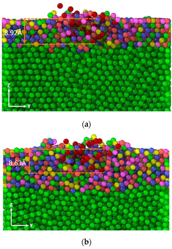
Figure 7.
Vertical section of the CoCrNiFeAlx-Al model. (a) Thickness of cladding layer—10 Å. (b) Thickness of cladding layer—15 Å.
4.2. Structural Changes during Bombardment
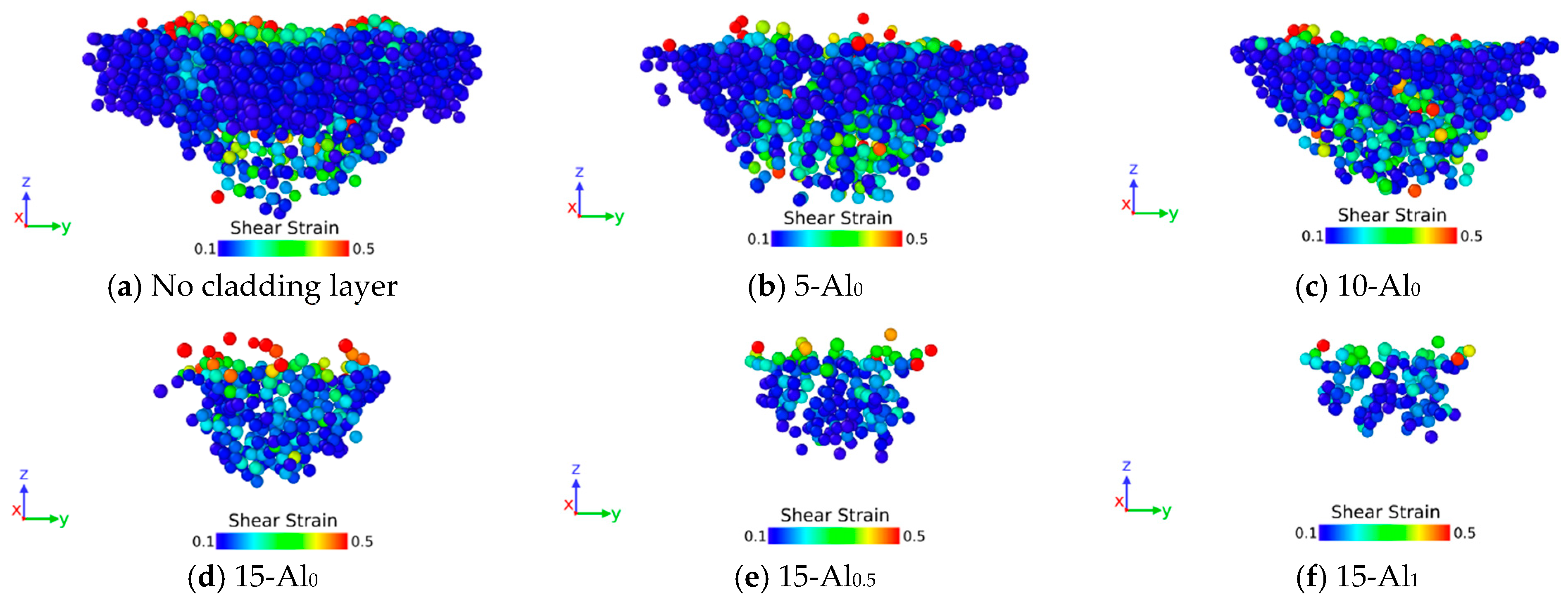
To further investigate microstructural changes due to bombardment, atomic shear strains were calculated using Ovito [32,33]. Figure 8a,b shows atomic strain clouds for the pure aluminum alloy model and the CoCrNiFeAlx–aluminum alloy model (15-Al0.5 means the fusion cladding layer thickness is 15 Å, and the Al content of the fusion cladding layer is 12 at%); only atoms with shear strains above 0.1 are retained in the strain clouds of both models to better distinguish differences between them. As shown, adding CoCrNiFeAlx fusion cladding significantly reduces strain depth and width. When the cladding layer is thin (as in 5-Al0), the improvement in strain is mainly reflected in width, as this thickness is insufficient to completely block aluminum atom bombardment, but the surface high-entropy alloy layer can still disperse impact pressure. Further thickening the cladding layer greatly reduces strain range, controlling it within the modified layer. Comparing the three figures of 15-Al0, 15-Al0.5, and 15-Al1, it can be found that with the increase in Al element, the strain range is further contracted, the shape of the strain cloud is flatter, and the number of atoms with larger strains on the surface is reduced, which indicates that the impact pressure is more dispersed and decays faster in the surface-modified armature model, and the addition of Al further improves the impact resistance of the material [34]. This is because the addition of the Al element makes the grain of the fusion cladding layer more refined, which can be dispersed in more grains when deformation occurs by external impact, resulting in a more uniform deformation and smaller stress concentration; in addition, the finer the grain, the larger the area of the grain boundary, and the more zigzagging the boundary, which is less favorable to the expansion of the impact.
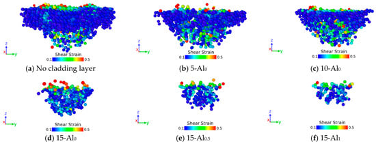
Figure 8.
Partial atomic shear strain cloud map of the CoCrNiFeAlx-Al model.
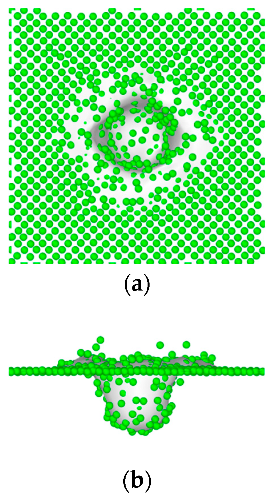
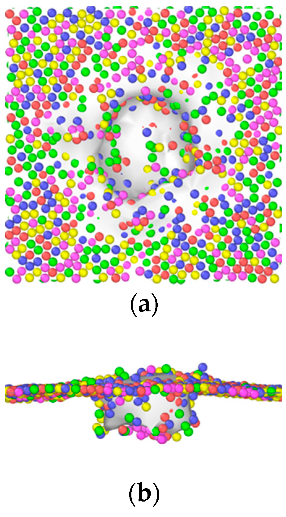
To elucidate the origin of strain depth differences, Ovito was employed to analyze the morphological evolution of the material surface during bombardment. The bombardment crater of the uncoated armature was more regular and hemispherical (Figure 9). The kinetic energy of the aluminum beam striking the armature material at high speed was converted into reverse impact pressure. This pressure caused the armature material to be extruded due to surface tension, resulting in an obvious splashing phenomenon. On the other hand, the CoCrNiFeAlx-Al model exhibited an irregular impact surface morphology with no obvious splash phenomenon (Figure 10). The impact crater was more flat, and the bottom had an obvious tendency to develop toward the xy plane. This was consistent with the results of the strain cloud diagram.
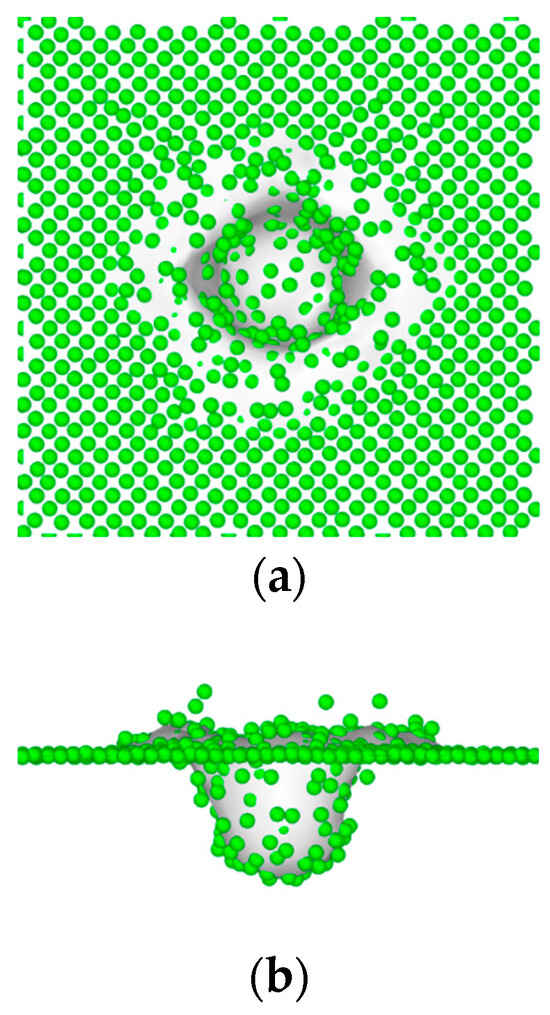
Figure 9.
Surface morphology of the pure aluminum alloy model after being bombarded. (a) Top view. (b) Front view.
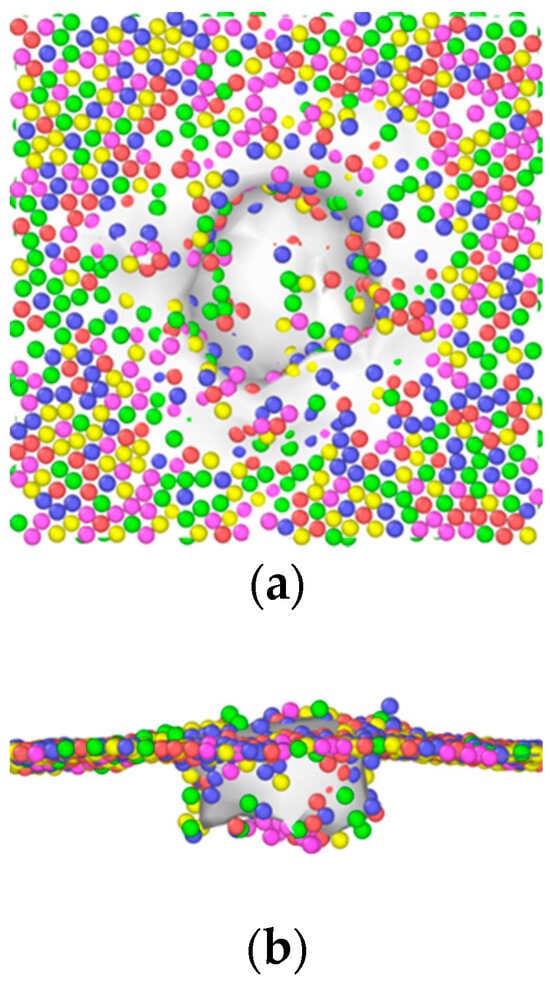
Figure 10.
Surface morphology of the CoCrNiFeAlx-Al model after being bombarded. (a) Top view. (b) Front view.
4.3. Degree of Surface Damage to the Aluminum Matrix
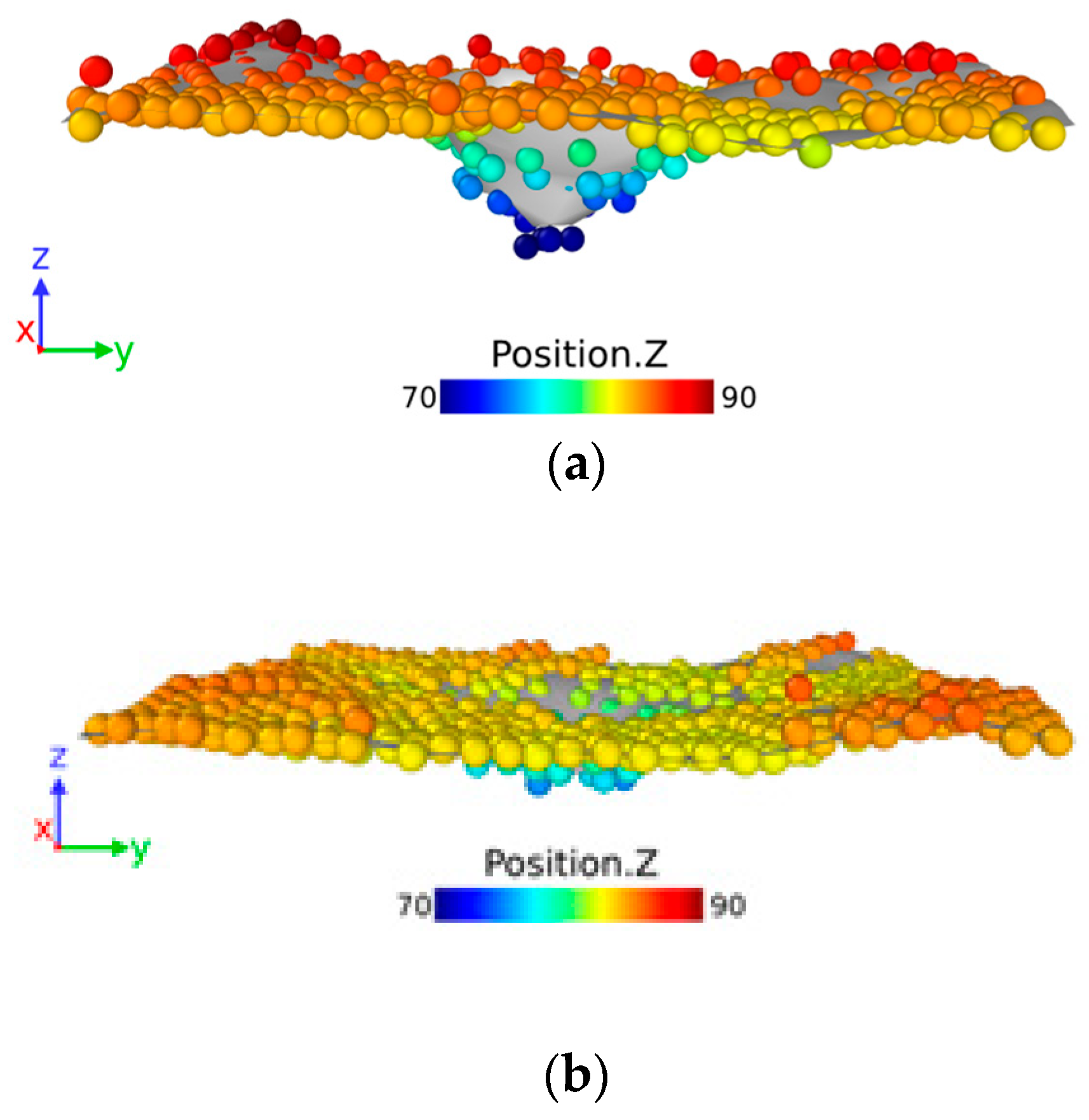
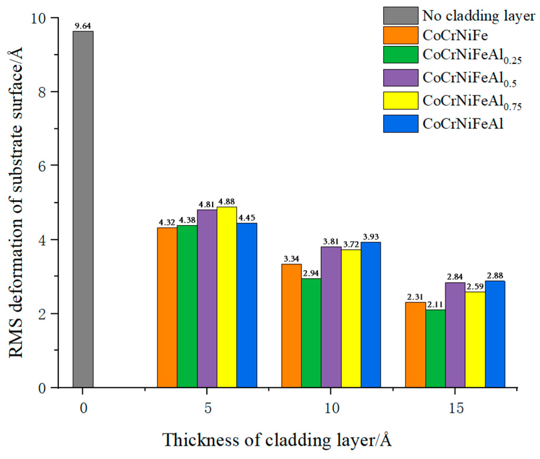
As shown in Figure 11, the damage morphology of the aluminum substrate surface after bombardment and stabilization is demonstrated in the form of 5-Al0.25 and 15-Al0.25, for example. The cladding layer is a CoCrNiFeAl0.25 aluminum alloy model with a thickness of 5 or 15 Å. The damage degree of the aluminum substrate surface is characterized by the RMS deformation of the substrate, as shown in Figure 12. Compared with the pure aluminum alloy model, the deformation of the substrate surface of the model with the CoCrNiFeAlx cladding layer is reduced by more than 50%, and the cladding layer effectively reduces the damage caused by bombardment to the material, providing a good protective effect. The CoCrNiFeAl0.25 fused cladding with a thickness of 15 Å provides the best protection to the substrate. The reason is that after adding the cladding layer, in the process of downward propagation of the shock wave, the distorted high-entropy alloy lattice structure in the cladding layer can reduce the speed of the shock wave by reflecting the shock wave several times, and there is a loss of impact energy [35]. In addition, increasing the thickness of the cladding layer is equivalent to increasing the number of reflections before the shock wave reaches the substrate, which can have a better dissipation effect, thus reducing the damage of the bombardment on the material. In addition to the influence of the thickness of the cladding layer, the content of Al in the cladding layer is also an important influence. Pure aluminum exhibits poor plastic deformation resistance, incurring greater bombardment damage. Al provides interstitial or replacement atoms in solid solution formation, enhancing lattice distortion and shock wave energy dissipation as well as improving cladding protective effects. However, matrix damage increases with further Al content, which is presumably due to tightly arranged Al atoms forming shock wave transmission channels, reducing high-entropy alloy cladding protection.
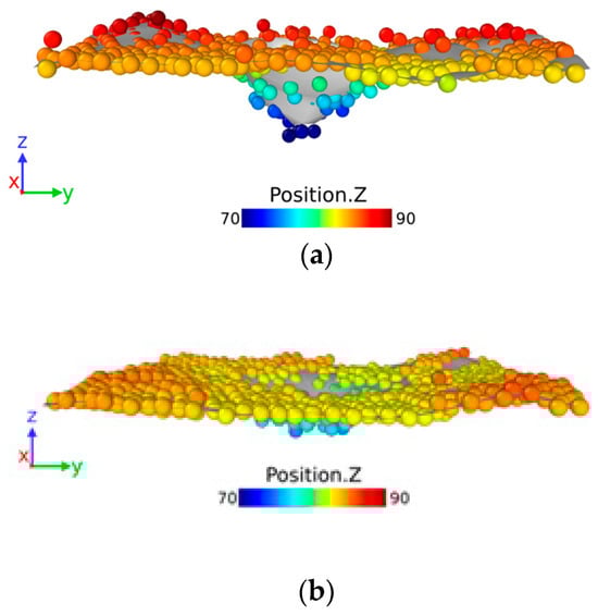
Figure 11.
Cloud map of surface damage morphology of the substrate after system stabilization. (a) 5-Al0.25. (b) 15-Al0.25.

Figure 12.
The degree of damage to the substrate surface of CoCrNiFeAlx-Al model.
In summary, adding a fused cladding layer reduces bombardment damage to the substrate. The thicker the cladding layer, the better it protects the substrate. For a given thickness, mixing appropriate Al improves the cladding layer’s protective effect. The CoCrNiFeAl0.25 cladding layer with 15 Å thickness effectively resists structural impact from bombardment due to its large thickness and strong energy dissipation, dispersing shock waves and enhancing the armature structure.
5. Conclusions
In this paper, a model for surface modification of an aluminum alloy armature was developed. The study investigated the impact of CoCrNiFeAlx surface-modified material on the ablation resistance and structural changes of the armature under arc ablation at a microscopic level using molecular dynamics simulation. The main conclusions are as follows:
(1) The incorporation of a CoCrNiFeAlx fused cladding layer can significantly enhance the material’s resistance to high temperatures. Moreover, the higher the aluminum content in the fused cladding layer, the more pronounced the vaporization of the model. Therefore, to minimize the metal vapor content in the air, it is important to reduce the intrusion of the matrix aluminum element into the surface fused cladding layer during the preparation of a high-entropy alloy-modified armature. It is recommended to adopt a surface modification method with a low dilution rate of the fused cladding layer.
(2) The addition of CoCrNiFeAlx fused cladding can significantly reduce the depth of arc intrusion. The maximum intrusion depths from the bombardment of all CoCrNiFeAlx surface modification models are smaller than those of the pure aluminum alloy model in various scenarios. The CoCrNiFeAlx fused cladding layer effectively disperses concentrated impact loads and prevents the arc from penetrating deeper. When the bombarded aluminum ball fails to fully penetrate the high-entropy alloy cladding layer, the maximum depth of intrusion for each model does not vary significantly. There is a saturation phenomenon in the improvement of the thickness for the depth of intrusion.
(3) The CoCrNiFeAlx aluminum alloy model shows a narrower range of strain on the bombarded surface and a flatter shape of the bombardment crater. The mechanism involves the high-entropy alloy converting a portion of the z-axis impact pressure into the xy direction. The addition of aluminum further enhances the impact resistance of the material. The addition of aluminum refines fusion cladding grains, which helps to disperse deformation across more grains when subjected to external impact. This results in more uniform deformation and reduces stress concentration. Additionally, finer grains have larger areas of grain boundaries with more zigzagging boundaries, which hinders impact propagation.
(4) The addition of CoCrNiFeAlx fused cladding helps reduce damage caused by bombardment to the substrate. Damage to the surface of the aluminum substrate decreases as the fusion cladding thickness increases. The protective effect of fused cladding can be further enhanced by incorporating a moderate amount of aluminum. The CoCrNiFeAl0.25 fused cladding, with a thickness of 15 μm, can effectively withstand the structural effects of bombardment on the substrate due to its significant thickness and high dissipation capacity, which disperses shock wave energy more effectively.
In summary, the surface modification of CoCrNiFeAlx high-entropy alloys with a reasonable thickness can effectively enhance the high-temperature resistance and impact the strength of the base material as well as improve resistance to a muzzle arc. A comparison of simulation results shows that CoCrNiFeAl0.25 exhibits the best high-temperature resistance and impact strength, making it the most preferred choice. Unfortunately, due to time constraints, we were unable to provide experimental validation. As a preliminary study, this work elucidates the law and micromechanism of high-entropy alloy arc ablation resistance in armature surface modification. It provides a theoretical basis and technical support for preparing high-entropy alloy–aluminum alloy-modified armatures with superior ablation resistance performance. This has important scientific significance and engineering value for improving the reliability of electromagnetic orbit launch, extending service life, and accelerating military application.
Author Contributions
Conceptualization, L.Z., G.W. and S.L.; Methodology, Y.T., L.Z., G.W. and S.L.; Software, Y.T.; Validation, M.W.; Investigation, Y.T.; Resources, L.Z. and S.L.; Data curation, M.W. and C.F.; Writing—original draft, Y.T.; Writing—review & editing, L.Z., G.W., C.F. and S.L.; Visualization, Y.T., M.W. and C.F.; Supervision, G.W.; Project administration, L.Z.; Funding acquisition, L.Z. All authors have read and agreed to the published version of the manuscript.
Funding
This research was funded by the National Natural Science Foundation of China project 92166110.
Institutional Review Board Statement
Not applicable.
Informed Consent Statement
Not applicable.
Data Availability Statement
Data are contained within the article.
Conflicts of Interest
The authors declare no conflict of interest.
References
- Mcnab, I.R. Large-scale pulsed power opportunities and challenges. IEEE Trans. Plasma Sci. 2014, 42, 1118–1127. [Google Scholar] [CrossRef]
- Ma, W.M.; Lu, J.Y. Research Progress and Challenges of Electromagnetic Launch Technology. Trans. China Electrotech. Soc. 2023, 38, 3943–3959. [Google Scholar]
- Lu, J.Y.; Ma, W.M. Lectromagnetic Rail Launch Theory and Technology; Science Press: Beijing, China, 2020. [Google Scholar]
- Fair, H.D. The science and technology of electric launch. IEEE Trans. Magn. 2001, 37, 25–32. [Google Scholar] [CrossRef]
- Sanogo, S.; Messine, F.; Henaux, C.; Vilamot, R. Topology optimization for magnetic circuits dedicated to electric propulsion. IEEE Trans. Magn. 2014, 50, 7401013. [Google Scholar] [CrossRef]
- Meger, R.A.; Cairns, R.L.; Douglass, S.R.; Huhman, B.; Neri, J.M.; Carney, C.J.; Jones, H.N.; Cooper, K.; Feng, J.; Brintlinger, T.H.; et al. EM gun bore life experiments at naval research laboratory. IEEE Trans. Plasma Sci. 2013, 41, 1533–1537. [Google Scholar] [CrossRef]
- Li, F.; Liu, J.X.; Huang, X.; Zhang, G. Porous Ultra-High Temperature Ceramics: Preparation, Structure and Properties. J. Chin. Ceram. Soc. 2018, 46, 669–1684. [Google Scholar]
- Zhou, H.T.; Xiong, X.Y.; Luo, F.; Luo, B.-W.; Liu, D.-B.; Shen, C.-M. Graphene enforced copper matrix composites fabricated by in-situ deposition technique. Acta Phys. Sin. 2021, 70, 086201. [Google Scholar] [CrossRef]
- Wang, L.; Cui, Y.; Li, B.; Yang, S.; Li, R.; Liu, Z.; Vajtai, R.; Fei, W. High apparent strengthening efficiency for reduced graphene oxide in copper matrix composites produced by molecule-lever mixing and high-shear mixing. Rsc. Adv. 2015, 5, 51193–51200. [Google Scholar] [CrossRef]
- Song, H.Y.; Zha, X.W. Mechanical properties of Ni-Coated single graphene sheet and their embedded aluminum matrix composites. Commun. Theor. Phys. 2010, 54, 143–147. [Google Scholar]
- Xing, K.; Xu, H.B.; Yan, C.; Chen, G.; Chen, M.; Zhu, Y. Research Progress on Interface Properties of Carbon Fiber Reinforced High Performance Thermoplastics Composite. Compos. Sci. Eng. 2019, 110–115. [Google Scholar]
- Zhang, Y.; Wang, X.Y.; Yu, J.; Cao, W.; Feng, P.; Jiao, S. Advances in Surface Modification of Molybdenum and Molybdenum Alloys at Elevated Temperature. Mater. Rep. 2017, 31, 83–87. [Google Scholar]
- Zhang, W.R.; Peter, K.L.; Zhang, Y. Science and technology in high-entropy alloys. Sci. China Mater. 2018, 61, 2–22. [Google Scholar] [CrossRef]
- Zhang, G.J.; Tian, Q.W.; Yin, K.X.; Niu, S.Q.; Wu, M.H.; Wang, W.W.; Wang, Y.N. Effect of Fe on microstructure and properties of AlCoCrFex Ni (x = 1.5, 2.5) high entropy alloy coatings prepared by laser cladding. Intermetallics 2020, 119, 106722. [Google Scholar] [CrossRef]
- Xu, Y.; Li, Z.; Liu, J.; Chen, Y.; Zhang, F.; Wu, L.; Hao, J.; Liu, L. Microstructure Evolution and Properties of Laser Cladding CoCrFeNiTiAlx High-Entropy Alloy Coatings. Coatings 2020, 10, 373. [Google Scholar] [CrossRef]
- Qiu, X.W.; Liu, C.G. Microstructure and properties of Al2CrFeCoCuTiNix high-entropy alloys prepared by laser cladding. J. Alloys Compd. 2013, 553, 216–220. [Google Scholar] [CrossRef]
- Guo, Y.; Shang, X.; Liu, Q. Microstructure and properties of in-situ TiN reinforced laser cladding CoCr2FeNiTi high-entropy alloy composite coatings. Surf. Coat. Technol. 2018, 344, 353–358. [Google Scholar] [CrossRef]
- Parks, P.B. Current melt-wave model for transitioning solid armature. J. Appl. Phys. 1990, 67, 3511–3516. [Google Scholar] [CrossRef]
- James, T.E. Current wave and magnetic saw-effect phenomena in solid armatures. IEEE Trans. Magn. 1995, 31, 622–627. [Google Scholar] [CrossRef]
- Tang, L.L. Experimental and Theoretical Study on Liquid Metal Film Characteristic of Armature/Rail Contact Interface in an Electromagnetic Launching; Huazhong University of Science and Technology: Wuhan, China, 2015. [Google Scholar]
- Benilov, M.S. Space-charge sheath with ions accelerated into the plasma. J. Phys. D Appl. Phys. 2010, 43, 175203. [Google Scholar] [CrossRef]
- Wang, Q.P. Electrical Arc Theory; Machinery Industry Press: Beijing, China, 1991; pp. 55–56. [Google Scholar]
- Cui, X.L. Research on Contact Erosion Mechanism and Material Transfer Characteristics under Direct Current Arc; Harbin Institute of Technology: Harbin, China, 2015. [Google Scholar]
- Plimpton, S. Fast parallel algorithms for short-range molecular dynamics. J. Comput. Phys. 1995, 117, 1–19. [Google Scholar] [CrossRef]
- Deluigi, O.R.; Pasianot, R.C.; Valencia, F.J.; Caro, A.; Farkas, D.; Bringa, E. Bringa, Simulations of primary damage in a High Entropy Alloy: Probing enhanced radiation resistance. Acta Mater. 2021, 213, 116951. [Google Scholar] [CrossRef]
- Zhou, X.; Johnson, R.; Wadley, H. Misfit-energy-increasing dislocations in vapordeposited CoFe/NiFe multilayers. Phys. Rev. B 2004, 69, 144113. [Google Scholar] [CrossRef]
- Zhou, X.W.; Wadley, H.N.G. Atomic scale structure of sputtered metal multilayers. Acta Mater. 2001, 49, 4005–4015. [Google Scholar] [CrossRef]
- Hong, Z.C. Plasma flow and arc extinguishing performance. Electr. Energy Manag. Technol. 1981, 610–667. [Google Scholar]
- Stukowski, A. Structure identification methods for atomistic simulations of crystalline materials. Model. Simul. Mater. Sci. Eng. 2012, 20, 045021. [Google Scholar] [CrossRef]
- Chen, B.R.; Yeh, A.C.; Yeh, J.W. Effect of one-step recrystallization on the grain boundary evolution of CoCrFeMnNi high entropy alloy and its subsystems. Sci. Rep. 2016, 6, 22306. [Google Scholar] [CrossRef]
- Zhang, W.; Xu, Q.; Wu, S.S. Microstructure and Mechanical Properties of NbMoTiVSix Refractory High Entropy Alloy. Chin. J. Rare Met. 2023, 47. [Google Scholar]
- Shimizu, F.; Ogata, S.; Li, J. Theory of shear banding in metallic glasses and molecular dynamics calculations. Mater. Trans. 2007, 48, 2923–2927. [Google Scholar] [CrossRef]
- Falk, M.L.; Langer, J.S. Dynamics of viscoplastic deformation in amorphous solids. Phys. Rev. E 1998, 57, 7192. [Google Scholar] [CrossRef]
- Liu, W.D.; Mi, G.F.; Li, L. Research Progress in lnfluence of Composition and Content on Laser Cladding High-entropy Alloy Coating. Spec. Cast. Nonferrous Alloys 2022, 42, 847–855. [Google Scholar] [CrossRef]
- Xie, H.C.; Ma, Z.C.; Zhang, W.; Zhao, H.; Ren, L. Amorphization transformation in high-entropy alloy FeNiCrCoCu under shock compression. J. Mater. Sci. Technol. 2024, 175, 72–79. [Google Scholar] [CrossRef]

Disclaimer/Publisher’s Note: The statements, opinions and data contained in all publications are solely those of the individual author(s) and contributor(s) and not of MDPI and/or the editor(s). MDPI and/or the editor(s) disclaim responsibility for any injury to people or property resulting from any ideas, methods, instructions or products referred to in the content. |
© 2024 by the authors. Licensee MDPI, Basel, Switzerland. This article is an open access article distributed under the terms and conditions of the Creative Commons Attribution (CC BY) license (https://creativecommons.org/licenses/by/4.0/).