Article

Coconut-Solid-Waste-Derived Hard-Carbon Anode Materials for Fast Potassium Ion Storage

1
School of Materials Science and Engineering, Wuhan University of Technology, Wuhan 430070, China
2
Sanya Science and Education Innovation Park of Wuhan University of Technology, Sanya 572000, China
3
Department of Physical Science & Technology, School of Science, Wuhan University of Technology, Wuhan 430070, China
*
Authors to whom correspondence should be addressed.
Coatings 2024, 14(2), 208; https://doi.org/10.3390/coatings14020208
Submission received: 22 December 2023 / Revised: 3 February 2024 / Accepted: 3 February 2024 / Published: 6 February 2024

Abstract

:
Hard carbon, which features recyclability, low costs, and environmental friendliness, is an attractive anode material for K+ storage. Nevertheless, the state-of-the-art hard carbon is still unsatisfactory due to its poor multiplication performance and unclear energy storage mechanism. In this study, a one-pot carbonisation method using coconut solid waste biomass is applied to obtain high-performance hard-carbon (CHC) anode materials. The microstructure and electrochemical properties of the CHC are investigated at different carbonisation temperatures (1100–1500 °C). The CHC materials prepared at 1300 °C (CHC1300) have a high capacity of 265.8 mAh g−1 at a current density of 25 mA g−1 and a superior cyclability of 1000 cycles at 1.0 A g−1 with a capacity retention of 96.6%. This approach, referred to as the “biomass-to-application” strategy, holds promise for advancing the development of cost-effective and sustainable KIBs.

1. Introduction

In recent years, the growing usage of and demand for fossil energy has contributed to global warming and climate damage. However, renewable energy sources, such as wind, solar, and tidal energies, are green, and other non-polluting alternatives are unstable and uneasy to harvest compared to fossil fuels. Moreover, these intermittent energies need devices to store the energy produced [1,2,3,4], and lithium-ion batteries (LIBs) are widely applied owing to their superior energy density [5,6,7]. However, due to the fast-growing demand for and the scarcity of lithium resources, alternatives to costly LIBs are seriously demanded. Potassium-ion batteries (KIB) are one attractive candidate due to the high reserves, low cost, and low redox potential (−2.93 V vs. E0) of potassium [8,9,10,11,12,13,14]. The low redox potential implies that KIBs could also have a high energy density [15]. Moreover, possessing a weaker Lewis acidity, K+ has small a Stokes radius (3.6 Å), and, thus, K+ electrolytes probably have rapid ionic conductivities [16]. Nevertheless, the large ionic radius of K+ can lead to a large volume expansion of the electrode materials, which severely limits the development of KIBs [17,18]. Therefore, the design of high-performance and sustainable anode materials is of great significance to accelerate the further development of KIBs.
Hard carbon (HC), which consists of disordered and ordered domains with proper lattice spacing and abundant defects, has proven to be efficient for K+ storage. Due to the random distribution of disordered and ordered domains, HC also has abundant interfaces for K+ storage and fast diffusion [19,20,21,22]. Therefore, HC materials are considered promising KIB anode materials. However, the fabrication of HC commonly demands complicated or time-consuming processes. Recently, biomass resources, featuring sustainability and low costs, have been widely investigated as precursors to produce HC. Up to now, different natural biomass materials, such as macadamia nut shells [23], bananas [24], wood [25], sugarcane [26], and corn cobs [27], have been used to produce HC through high-temperature (usually >1000 °C) carbonisation. It is widely accepted that the carbonisation temperature and the initial macromolecular and chemical structure of the precursor have a strong influence on the properties of HC. These derived HC materials commonly have a reduced graphite interlayer space, defects, and functional groups [28]. Different biomass-derived HC materials show diverse reversible/irreversible capacities, and the carbonisation temperature range of 1100–1500 °C is beneficial for K+ deintercalation and the long-term cycling capacity [29]. However, the limited rate capability of HC is still a significant challenge, and the corresponding ion diffusion and storage mechanisms need a comprehensive understanding. Coconut meat, like bananas and sugarcane, which have shown a superior K+ storage capability, also has numerous oxygen-containing groups and therefore can induce abundant mesopores and variable lattice interlayer structures after carbonisation. Large interlayer spacings have positive effects on K+ diffusion and lattice expansion and shrinkage, and, thus, superior K+ intercalation/extraction can be guaranteed.
In this work, we use coconut solid waste as a precursor to obtain hard-carbon (CHC) anode materials via one-pot carbonisation without an additional activation process. The effects of different carbonisation temperatures (1100–1500 °C) on the morphology and performance of the CHCs are investigated. The obtained CHCs feature abundant mesopores that are beneficial for electrolyte wetting and promoting ion diffusion. In result, the CHCs exhibited a high capacity of 265.8 mAh g−1 at a current density of 25 mA g−1 and an excellent cyclability, with 96.6% capacity being maintained over 1000 cycles at 1 A g−1. This work provides a one-pot carbonisation path using coconut solid waste as a precursor to obtain high-performance anode materials for KIBs. Section 1 is the introduction of the developments and challenges of HC anode materials for KIBs, and it includes our strategy for building high-performance HC anodes. Section 2 is devoted to providing detailed information about the material synthesis and characterisations. Section 3 contains the description of our experiments and the corresponding discussion of the results. Section 4 is our conclusion.

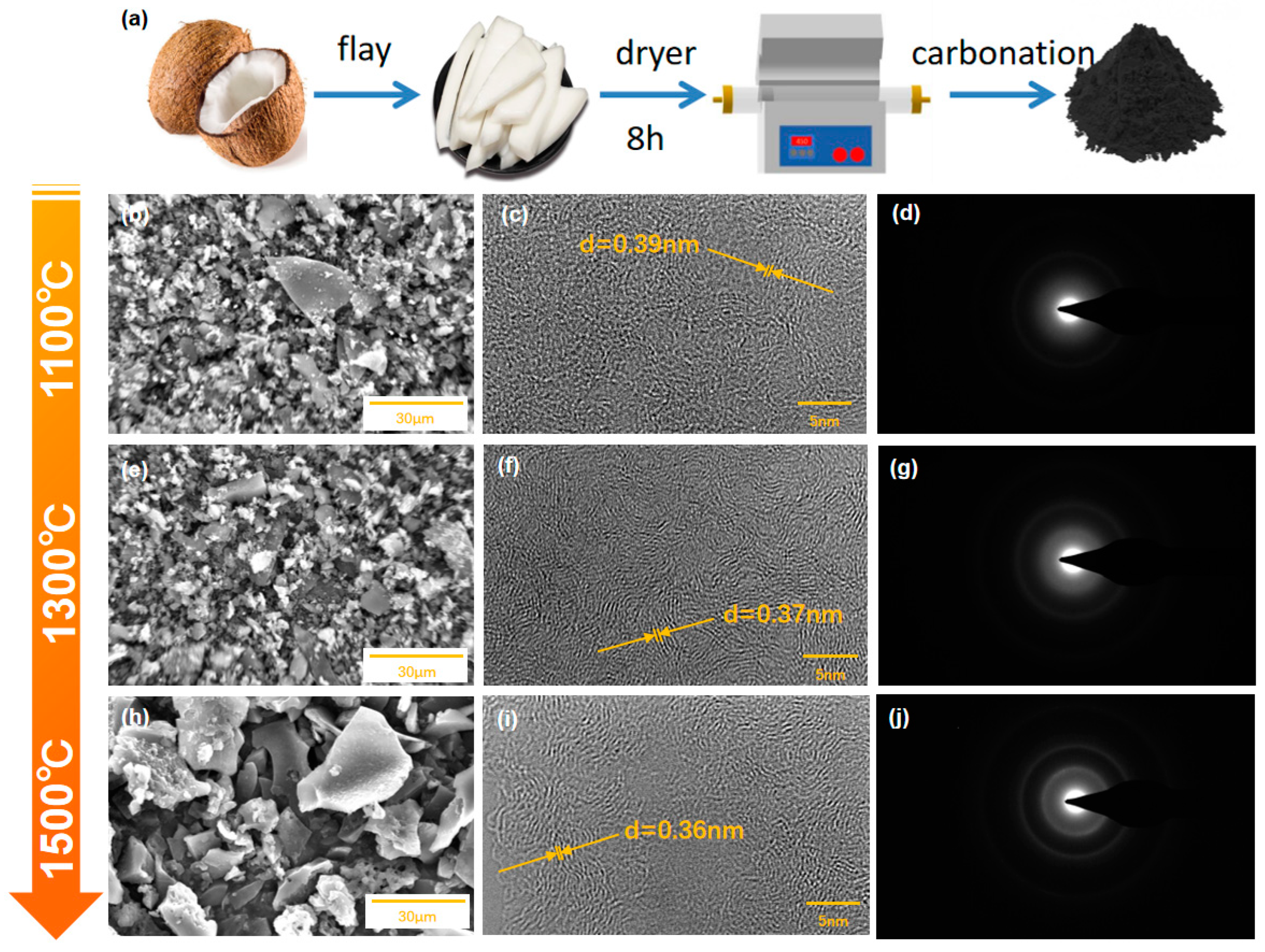
2. Materials, Methods

2.1. Synthesis of CHC Samples

We used a one-step carbonation method to prepare the CHCs, and the synthetic route is shown in Figure 1. Discarded coconuts that were obtained from a market were recycled, and the coconut meat was removed, cut into small pieces, and dried at 80 °C for 12 h, and it was then ground into powder particles in a household grinder. After that, the obtained samples were carbonised at 1100–1500 °C under argon for 3 h. The carbonised samples were then washed with aqueous hydrochloric acid to remove inorganic magazines.

2.2. Material Characterisations
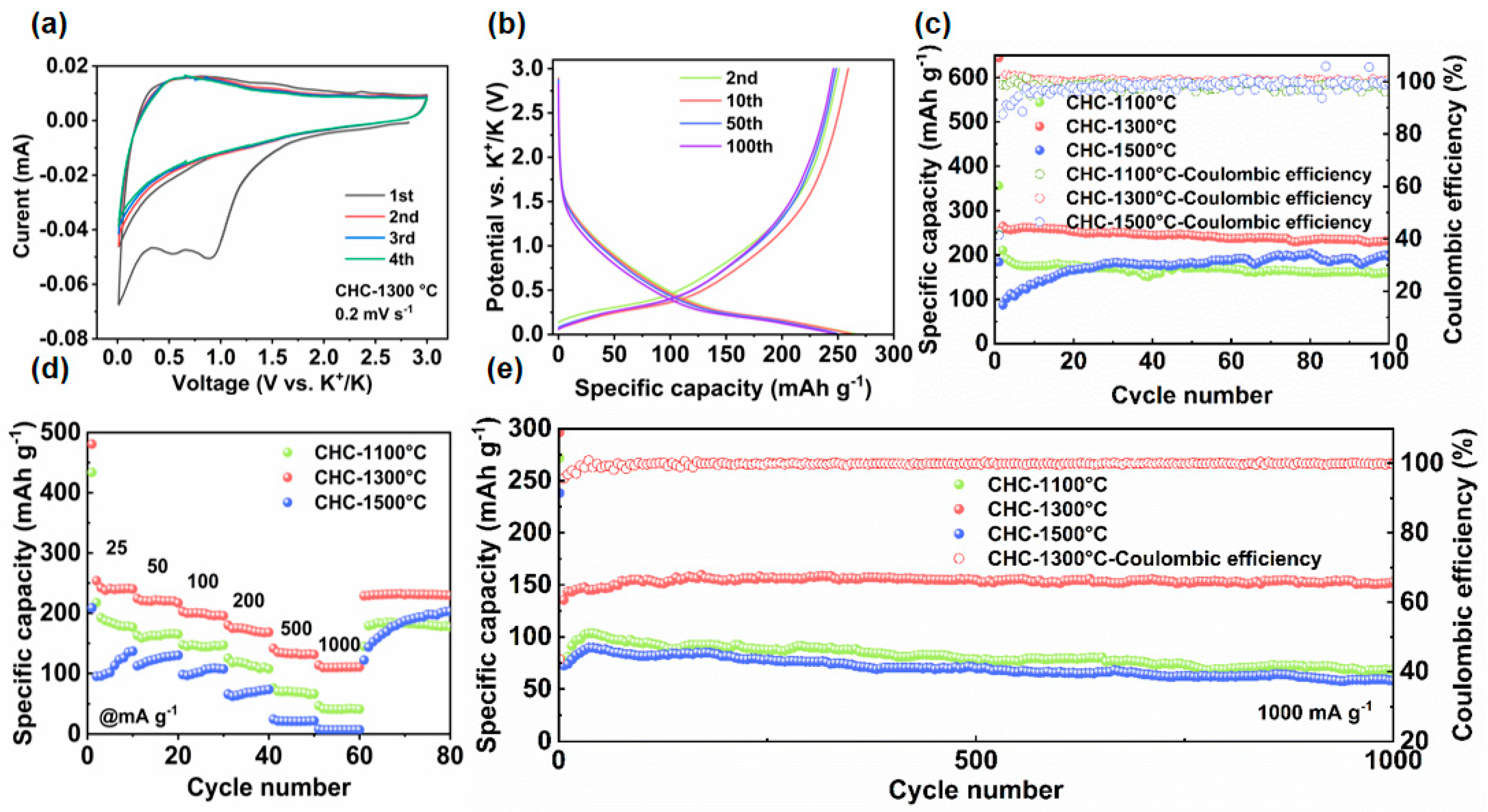
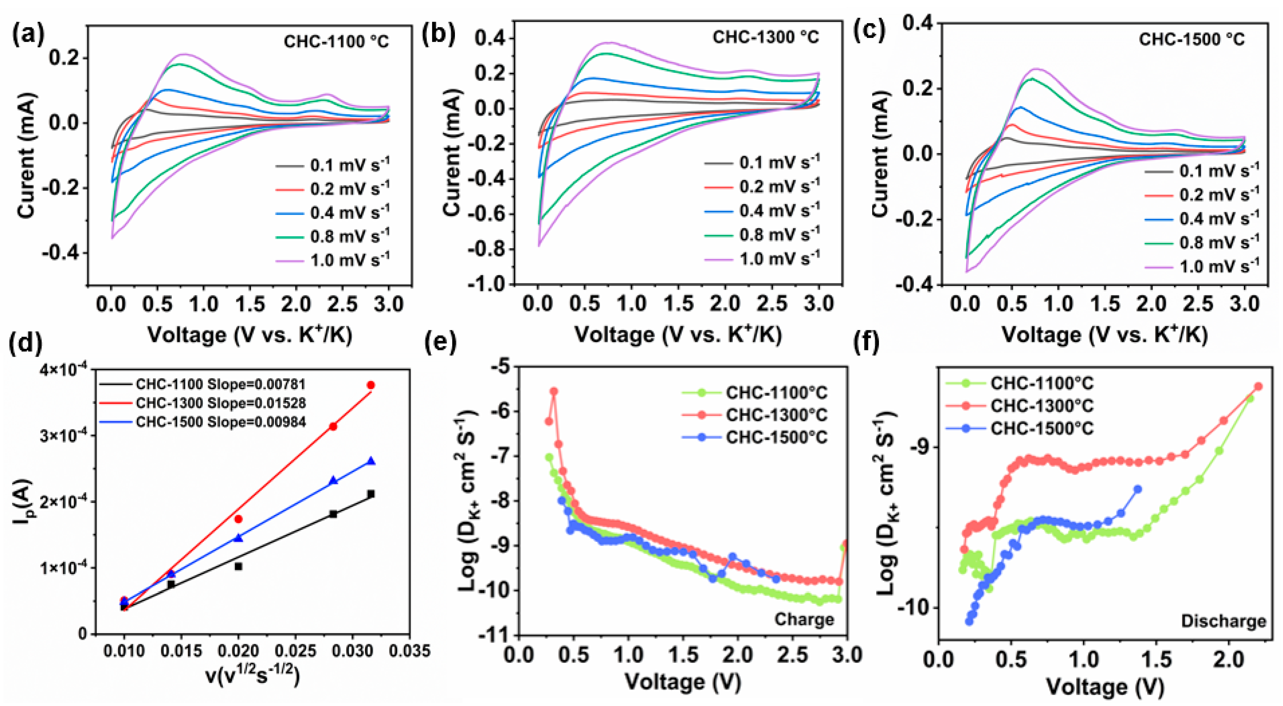
The obtained hard carbon and super P were mixed at a ratio of 80:10 and then mixed with a sodium carboxymethyl cellulose (CMCNa) binder at a mass ratio of 90:10 in deionised water, and the slurry was uniformly pasted onto aluminium foil and vacuum-dried at 100 °C for 12 h. The mass loading of the electrodes with the active material was approximately 0.9–1.3 mg cm–2. Electrochemical measurements were performed using a 2016-coin cell with a glass fibre filter (Whatman GF/D, Whatman, Shanghai, China) as the separator, 5 M potassium difluorosulfonimide (KFSI) dissolved in dimethyl ether (DME) as the electrolyte, and potassium metal as the anode. The coin cell was assembled in an argon-filled glove box. Constant-current charge/discharge cycling tests were performed over a voltage range of 0.01–3.0 V.

3. Results

3.1. Morphology and Structural Characterisation

The SEM images showed that the CHC1100, CHC1300, and CHC1500 samples consisted mainly of irregular blocks and small particles with sizes ranging from 5 to 30 µm (Figure 1b,e,h). The EDS mapping and EDX spectra (Figures S1–S3) showed that all the samples mainly contained C and O elements and were of a high purity. The average particle size showed no significant change as the carbonisation temperature increased from 1100 °C to 1300 °C, and the CHC1500 sample obviously had a much larger average particle size. The high-resolution TEM (HRTEM) images of the CHC1100, CHC1300, and CHC1500 samples, shown in Figure 1c,f,i, respectively, displayed disordered and ordered domains. With the increase in the carbonisation temperature, the size of the crystal domains increased, the spacing between the graphite layers decreased, and the graphitised extent increased [30]. The graphite interlayer spacing was mainly between 0.39~0.41 nm, 0.37~0.39 nm, and 0.35~0.37 nm for the CHC1100, CHC1300, and CHC1500 samples, respectively. The selected area electron diffraction (SAED) from the CHC1100 sample (Figure 1d) showed rather diffuse diffraction rings. The diffraction rings became more pronounced as the carbonisation temperature increased (Figure 1g,j), confirming the partial graphitisation of the CHC1100 sample. The CHC1300 sample had a more homogeneous local structure compared to the other two samples. The observed mixture of disordered and graphited regions was similar to the “house of cards” model [31], where closed pores were formed between these regions.
The XRD patterns of the CHC at different temperatures showed two major peaks at approximately 24° and 43°, assigned to the (002) and (100) lattice planes of graphite, respectively (Figure 2a) [32]. The lattice spacing of (002) can be determined via the Bragg equation:
d 002 = λ 2 sin θ
The average interlayer spacing of the CHC1100, CHC1300, and CHC1500 samples were calculated to be 3.88 Å, 3.71 Å, and 3.64 Å, respectively. Also, as the carbonisation temperature increased, the (002) diffraction peaks were sharper and offset to a higher angle, indicating an increased crystallinity and reduced interlayer spacing [33]. These d002 were bigger than that of graphite, which is beneficial to K+ transport [34,35]. The (002) diffraction peak became shaper and shifted to higher degree with the increase in the carbonisation temperature, indicating an increased crystallinity and decreased interlayer spacing. The average size of the graphite microcrystalline domains along the c-axis (Lc) and ab plane (La) can be calculated according to the Scherrer equation [36]:
L = K λ B cos θ
where K is Scherrer’s constant, and B is the half-height width of the diffraction peak; when K = 0.89, B is the half-height width of the diffraction peak of the measured sample (with bilinear and instrumental factor correction), which is converted to radians in the calculation process. The calculated Lc values for the CHC1100, CHC1300, and CHC1500 samples were 2.6, 3.0, and 3.6 nm, respectively, and the La values were 9.8, 12.1, and 14.8, respectively. The particle size of the CHC samples grew as the temperature increased, which was consistent with the SEM observation.
The chemical and physical structures of the CHCs were carefully studied. Two intense peaks at approximately 1346 and 1596 cm−1, derived from the D and G bands, respectively, were observed in the Raman spectroscopy (Figure 2b) [37]. The intensity ratio (i.e., ID/IG, area ratio) reflects the disordered degree in carbon materials, and the obtained values were 2.06 for CHC1100, 2.02 for CHC1300, and 1.65 for CHC1500 (Figure S4) [38,39,40]. The ID/IG decrease coincided with the gradual increase in the degree of localised graphitisation [41], which was in good accordance with the TEM and XRD results.
The X-ray photoelectron spectroscopy (XPS) measurements were used to provide complementary insights into the valent state of the CHC1300 sample. The survey spectrum of the CHC1300 sample showed two distinct peaks at ~284 and ~532 eV, which were derived from the C 1s and O 1s signals, respectively (Figure S5) [42]. The relative contents of C and O were measured to be 89.73% and 9.55%, respectively. The deconvoluted peaks in the C 1s spectra (Figure 2c) were derived from the COOR (290.38 eV), C=C (284.7 eV), C−O (286.1 eV), and C=O groups (287.8 eV). Three different oxygen-containing groups, i.e., OH− (531.2 eV), C=O (532.5 eV), and C−O (533.9 eV), were observed in the O 1s spectra of the CHC1300 sample (Figure 2d). The microstructure information of the CHCs was evaluated by nitrogen adsorption/desorption isotherms (Figure 2e,f). Comparing the XPS spectra among the three samples, the contributions of C sp2 were 90.4%, 86.9%, and 78.3% for the CHC1500, CHC1300 (Table S1), and CHC1100 samples, respectively, and correspondingly, the oxygen contents were 20.7%, 12.3%, and 9.0% for the CHC1100, CHC1300, and CHC1500 samples, respectively (Figures S6 and S7), showing an apparent decrease in oxygen-containing groups along with the temperature increase. The BET specific surface areas of the CHC1100, CHC1300, and CHC1500 samples were 188, 291, and 354 m2 g−1, respectively. All the CHC samples showed type IV nitrogen isotherms. Such isotherms confirmed the presence of mesopores of ~3–4 nm in all the CHCs (Figure 2f). At P/P0 > 0.9, the N2 adsorption branch increased significantly, indicating that the CHC1300 and CHC1500 samples contained a large number of cleavage-like pores.

3.2. Electrochemical Measurements

The resulting CHCs were tested as anode materials for KIBs. In the first cycle of the cyclic voltammetry (CV) curves, a broad reduction peak at about 1.0 V (potassiumisation) was observed, which usually derives from electrolyte decomposition and the formation of a solid electrolyte interface (SEI) layer, and the peak situated at 0.57 V corresponded to the depotassiumisation process (Figure 3a). After the initial cycle, the CV curves overlapped, which indicates the highly reversible de-/potassiumisation in the CHC1300 electrode. The discharge capacities of the CHC1300 electrode at the 2nd, 10th, 50th, and 100th cycles were 264.8, 262.55, 250.3, and 246.3 mAh g−1, respectively (Figure 3b). It can be seen from the initial charging and discharging curves at different current densities that the CHC1300 electrode had a higher discharge plateau and capacity than the CHC1100 and CHC1500 ones (Figure S8). The almost completely overlapping charge/discharge curves at the 10th and 100th cycles further indicate that the CHC1300 material had good reversibility and cycling stability for use as a KIB anode (Figure S9). The initial irreversible discharge plateau between 0.5–1.3 V was mainly derived from the side-reaction at the electrode–electrolyte interface, which showed a similar trend to that of the CV curves.
The electrochemical performances of the different samples (CHC1100, CHC1300, and CHC1500) were compared. After the initial SEI formation cycle, the maximum reversible capacity at 25 mA g−1 of the CHC1300 sample (except in the first circle) was 265.8 mAh g−1 (Figure 3c), which was superior to that of the CHC1100 (210.5 mAh g−1) and CHC1500 (200.3 mAh g−1) samples. The capacity retention of the CHC1100, CHC1300, and CHC1500 samples after 100 cycles was 76.2%, 89.2%, and 42.9%, respectively. Notably, reversible capacities of the CHC1300 sample of 253, 224, 202, 180, 141, and 113 mAh g−1 were obtained at 25, 50, 100, 200, 500, and 1000 mA g−1, respectively. The capacity of the CHC1300 sample could recover to ~231 mAh g−1 as the current density returned to 25 mA g−1 (Figure 3d), corresponding to a capacity recovery of 91.3%. However, the CHC1100 and CHC1500 samples showed a poor rate capability. Figure 3e shows the cyclability of the CHC electrode over 1000 cycles at 1000 mA g−1. The capacity of the CHC1300 sample increased to 158.6 mAh g−1 after the initial activation process, of which 96.6% was maintained after 1000 cycles. However, the highest specific capacities of the CHC1100 and CHC1500 samples were 103.6 and 83.1 mAh g−1, and only 66.4% and 69.9% of those could be retained, respectively. It was shown that the CHC1300 sample had a higher specific capacity and cycling stability, which was attributed to the higher electronic conductivity and proper graphite interlayer spacing that ensured the efficient de-/potassiumisation. In comparison with previously reported carbon materials for KIBs (Table S2), our CHC1300 sample showed a superior K+ storage capability.
Electrochemical impedance spectroscopy (EIS) was applied to investigate the intrinsic ionic/electronic transfer properties of the CHC samples (Figure S10). The CHC1300 sample showed a steeper trend than the CHC1100 and CHC1500 samples at a low-frequency arrangement and, thus, had a faster ion diffusion. The smallest radius of the semi-arc of the CHC1300 electrode at a high-frequency arrangement shows that it also had the smallest charge transport resistance (Rct). The best electron transfer and ion diffusion kinetics support the fact that the CHC1300 sample had the superior electrochemical performance.
To further investigate the ion diffusion kinetics, the multi-sweep CVs were analysed, as shown in Figure 4a–d, through the Randles–Sevcik equation [6]:
I p = 0.4463 nFAC nF v D / RT 1 / 2 = 269000 n 3 / 2 AD 1 / 2 C v 1 / 2
where B = (269,000n3/2AD1/2C), n denotes the electron number transfer (Table S3), and A, F, and D denote the contact area (0.785 cm2), Faraday constant (C 1 mol−1), and diffusion coefficient (cm2 s−1), respectively. C is the K+ concentration (C = 5 M), and b represents the slope of the peak anodic current Ip vs. the square root of the scan rate (v1/2) (Figure 4d). The average DK+ in the electrode materials of the CHC1100, CHC1300, and CHC1500 samples were determined to be 8.549 × 10⁻¹¹, 3.273 × 10⁻¹⁰, and 1.357 × 10⁻¹⁰ cm2 s−1, respectively. The higher DK+ value of the CHC1300 sample sufficiently shows that the CHC1300 sample had a higher rate capability than the CHC1100 and CHC1500 samples (Figure 4a–d). Additionally, the galvanostatic intermittent titration technique (GITT) was applied to investigate the ion diffusion kinetics [43]. The DK+ value was calculated according to the following equation:
D G I T T = 4 π τ m B V M M B S 2 Δ E S Δ E τ 2
where τ is the current pulse time (s), mB is the active mass in the sample (g), VM and MB are the molar volume and molar mass of B (cm3 mol−1, g mol−1), respectively, and S is the active surface area of the CHC electrodes (cm2). ΔES and ΔEτ can be obtained from the GITT curves [42]. The DK+ value of the CHC1300 electrode was slightly higher than that of the CHC1100 and CHC1500 electrodes during the potassium removal (Figure 4e), during which the diffusion coefficients of the CHC electrode decreased rapidly and then slowly. Upon discharging, the CHC1300 sample had a much higher ion diffusion coefficients than the other samples (Figure 4f). The diffusion kinetics analyses showed that the diffusion coefficients of the CHC1300 sample were higher than those of the CHC1100 and CHC1500 samples. It can be concluded that the higher electronic/ionic conductivity, proper graphite interlayer spacing, and disordered and graphitised mixed domains contributed to the high capacity, superior rate capability, and excellent cycling stability of the CHC1300 sample, which could be regulated by the carbonisation temperature.

4. Conclusions

In general, this research provides a simple-yet-effective approach to convert waste residual coconut endocarp into high-performance anode materials for KIBs. The obtained CHC1300 had a high ionic/electronic conductivity and a proper microstructure, and it thus showed a high specific capacity of 265.8 mAh g−1, an excellent rate capability (154 mAh g−1 on average at 1000 mA g−1), and a stable cyclability (a capacity retention of 96.6% after 1000 cycles). This work demonstrates that the “biomass-to-application” strategy is promising for advancing the application of low-cost and sustainable KIBs.

Supplementary Materials

The following supporting information can be downloaded at: https://www.mdpi.com/article/10.3390/coatings14020208/s1. References [44,45,46,47,48,49] are cited in the supplementary materials.

Author Contributions

Conceptualization, Y.M.; Methodology, W.L. (Wenhao Liu); Software, H.W.; Validation, Y.W.; Formal analysis, W.L. (Wenhan Liu) and G.Z.; Writing—original draft, X.W.; Writing—review & editing, M.H.; Supervision, W.C. All authors have read and agreed to the published version of the manuscript.

Funding

This work was supported by the National Natural Science Foundation of China (52373306, 51832004), the Natural Science Foundation of Hubei Province (2023AFA053), and the Hainan Provincial Joint Project of Sanya Yazhou Bay Science and Technology City (2021CXLH0007).

Institutional Review Board Statement

Not applicable.

Informed Consent Statement

Not applicable.

Data Availability Statement

Data are contained within the article and supplementary materials.

Conflicts of Interest

The authors declare no conflicts of interest.

Abbreviations

KIBPotassium-ion battery
HCHard carbon
CHCHard carbon derived from coconut solid wastes
CMCNaSodium carboxymethyl cellulose
KFSIPotassium difluorosulfonimide
DMEDimethyl ether
TEMTransmission electron microscope
XRDX-ray diffraction
SEMScanning electron microscope
SAEDElectron diffraction
XPSX-ray photoelectron spectroscopy
BETBrunauer–Emmett–Teller
CVCyclic voltammetry
SEISolid electrolyte interface
EISElectrochemical impedance spectroscopy
GITTGalvanostatic intermittent titration technique

References

  1. Chen, S.; Wang, J.; Fan, L.; Ma, R.; Zhang, E.; Liu, Q.; Lu, B. An Ultrafast Rechargeable Hybrid Sodium-Based Dual-Ion Capacitor Based on Hard Carbon Cathodes. Adv. Energy Mater. 2018, 8, 1800140. [Google Scholar] [CrossRef]
  2. Yu, X.; Wang, B.; Gong, D.; Xu, Z.; Lu, B. Graphene Nanoribbons on Highly Porous 3D Graphene for High-Capacity and Ultrastable Al-Ion Batteries. Adv. Mater. 2017, 29, 1604118. [Google Scholar] [CrossRef] [PubMed]
  3. Cao, X.; Li, X.; Qiao, Y.; Jia, M.; Qiu, F.L.; He, Y.B.; He, P.; Zhou, H.S. Restraining Oxygen Loss and Suppressing Structural Distortion in a Newly Ti-Substituted Layered Oxide P2-Na0.66Li0.22Ti0.15Mn0.63O2. ACS Energy Lett. 2019, 4, 2409. [Google Scholar] [CrossRef]
  4. Kim, H.; Kim, J.C.; Bianchini, M.; Seo, D.H.; Rodriguez-Garcia, J.; Ceder, G. Recent Progress and Perspective in Electrode Materials for K-Ion Batteries. Adv. Energy Mater. 2018, 8, 1702384. [Google Scholar] [CrossRef]
  5. Wang, J.; Zhang, G.; Liu, Z.; Li, H.; Liu, Y.; Wang, Z.; Li, X.; Shih, K.; Mai, L. Li3V(MoO4)3 as a Novel Electrode Material with Good Lithium Storage Properties and Improved Initial Coulombic Efficiency. Nano Energy 2018, 44, 272–278. [Google Scholar] [CrossRef]
  6. Chen, S.; Fan, L.; Xu, L.; Liu, Q.; Qin, Y.; Lu, B. 100 K cycles: Core-shell H-FeS@C Based Lithium-Ion Battery Anode. Energy Storage Mater. 2017, 8, 20–27. [Google Scholar] [CrossRef]
  7. Zhang, X.Q.; Cheng, X.B.; Zhang, Q. Nanostructured Energy Materials for Electrochemical Energy Conversion and Storage: A Review. J. Energy Chem. 2016, 25, 967–984. [Google Scholar] [CrossRef]
  8. Fan, L.; Lin, K.; Wang, J.; Ma, R.; Lu, B. A Nonaqueous Potassium-Based Battery-Supercapacitor Hybrid Device. Adv. Mater. 2018, 30, e1800804. [Google Scholar] [CrossRef]
  9. Hwang, J.-Y.; Myung, S.-T.; Sun, Y.-K. Recent Progress in Rechargeable Potassium Batteries. Adv. Funct. Mater. 2018, 28, 1802938. [Google Scholar] [CrossRef]
  10. Jian, Z.; Luo, W.; Ji, X. Carbon Electrodes for K-Ion Batteries. J. Am. Chem. Soc. 2015, 137, 11566–11569. [Google Scholar] [CrossRef]
  11. Luo, W.; Wan, J.; Ozdemir, B.; Bao, W.; Chen, Y.; Dai, J.; Lin, H.; Xu, Y.; Gu, F.; Barone, V.; et al. Potassium Ion Batteries with Graphited Materials. Nano Lett. 2015, 15, 7671–7677. [Google Scholar] [CrossRef]
  12. Pramudita, J.C.; Sehrawat, D.; Goonetilleke, D.; Sharma, N. An Initial Review of the Status of Electrode Materials for Potassium-Ion Batteries. Adv. Energy Mater. 2017, 7, 1602911. [Google Scholar] [CrossRef]
  13. Beltrop, K.; Beuker, S.; Heckmann, A.; Winter, M.; Placke, T. Alternative Electrochemical Energy Storage: Potassium-Based Dualgraphite Batteries. Energy Environ. Sci. 2017, 10, 2090–2094. [Google Scholar] [CrossRef]
  14. Chen, Y.; Luo, W.; Carter, M.; Zhou, L.; Dai, J.; Fu, K.; Lacey, S.; Li, T.; Wan, J.; Han, X.; et al. Organic Electrode for Nonaqueous Potassium-Ion Batteries. Nano Energy 2015, 18, 205–211. [Google Scholar] [CrossRef]
  15. Fan, L.; Chen, S.; Ma, R.; Wang, J.; Wang, L.; Zhang, Q.; Zhang, E.; Liu, Z.; Lu, B. Ultrastable Potassium Storage Performance Realized by Highly Effective Solid Electrolyte Interphase Layer. Small 2018, 14, e1801806. [Google Scholar] [CrossRef] [PubMed]
  16. Marcus, Y. Thermodynamic Functions of Transfer of Single Ions from Water to Nonaqueous and Mixed Solvents: Part 3—Standard Potentials of Selected Electrodes. Pure Appl. Chem. 1985, 57, 1129. [Google Scholar] [CrossRef]
  17. Ramasamy, H.V.; Senthilkumar, B.; Barpanda, P.; Lee, Y.-S. Superior Potassium-Ion Hybrid Capacitor Based on Novel P3-Type Layered K0.45Mn0.5Co0.5O2 as High Capacity Cathode. Chem. Eng. J. 2019, 368, 235–243. [Google Scholar] [CrossRef]
  18. Ming, F.; Liang, H.; Zhang, W.; Ming, J.; Lei, Y.; Emwas, A.-H.; Alshareef, H.N. Porous MXenes Enable High Performance Potassium Ion Capacitors. Nano Energy 2019, 62, 853–860. [Google Scholar] [CrossRef]
  19. Chen, C.; Wang, Z.; Zhang, B.; Miao, L.; Cai, J.; Peng, L.; Huang, Y.; Jiang, J.; Huang, Y.; Zhang, L.; et al. Nitrogen-Rich Hard Carbon as a Highly Durable Anode for High-Power Potassium-Ion Batteries. Energy Storage Mater. 2017, 8, 161–168. [Google Scholar] [CrossRef]
  20. Chen, M.; Wang, W.; Liang, X.; Gong, S.; Liu, J.; Wang, Q.; Guo, S.J.; Yang, H. Sulfur/Oxygen Codoped Porous Hard Carbon Microspheres for High-Performance Potassium-Ion Batteries. Adv. Energy Mater. 2018, 8, 1800171. [Google Scholar] [CrossRef]
  21. Jian, Z.L.; Xing, Z.Y.; Bommier, C.; Li, Z.F.; Ji, X.L. Hard Carbon Microspheres: Potassium-Ion Anode Versus Sodium-Ion Anode. Adv. Energy Mater. 2016, 6, 1501874. [Google Scholar] [CrossRef]
  22. Wu, F.; Liu, L.; Yuan, Y.; Li, Y.; Bai, Y.; Li, T.; Lu, J.; Wu, C. Expanding Interlayer Spacing of Hard Carbon by Natural K+ Doping to Boost Na-Ion Storage. ACS Appl. Mater. Interfaces 2018, 10, 27030–27038. [Google Scholar] [CrossRef] [PubMed]
  23. Dahbi, M.; Kiso, M.; Kubota, K.; Horiba, T.; Chafik, T.; Hida, K.; Matsuyama, T.; Komaba, S.J. Synthesis of hard carbon from argan shells for Na-ion batteries. Mater. Chem. A 2017, 5, 9917–9928. [Google Scholar] [CrossRef]
  24. Lotfabad, E.M.; Ding, J.; Cui, K.; Kohandehghan, A.; Kalisvaart, W.P.; Hazelton, M.; Mitlin, D. High-density sodium and lithium ion battery anodes from banana peels. ACS Nano 2014, 8, 7115–7129. [Google Scholar] [CrossRef] [PubMed]
  25. Rios, C.D.M.S.; Simone, V.; Simonin, L.; Martinet, S.; Dupont, C. Biochars from various biomass types as precursors for hard carbon anodes in sodium-ion batteries. Biomass Bioenergy 2018, 117, 32–37. [Google Scholar] [CrossRef]
  26. Jiang, Q.; Zhang, Z.H.; Yin, S.Y.; Guo, Z.P.; Wang, S.Q.; Feng, C.Q. Biomass carbon micro/nano-structures derived from ramie fibers and corncobs as anode materials for lithium-ion and sodium-ion batteries. Appl. Surface Sci. 2016, 379, 73–82. [Google Scholar] [CrossRef]
  27. Zhu, T.; Mai, B.; Hu, P.; Cai, C.; Xing, B.; Wei, Z.; Chen, C.; Fan, H.; Li, M.; Wang, X. Bagasse-Derived Hard Carbon Anode with an Adsorption–Intercalation Mechanism for High-Rate Potassium Storage. ACS Appl. Energy Mater. 2023, 6, 2370–2377. [Google Scholar] [CrossRef]
  28. Ghimbeu, C.M.; Górka, J.; Simone, V.; Simonin, L.; Martinet, S.; Vix-Guterl, C. Insights on the Na+ ion storage mechanism in hard carbon: Discrimination between the porosity, surface functional groups and defects. Nano Energy 2018, 44, 327–335. [Google Scholar] [CrossRef]
  29. Gomez-Martin, A.; Martinez-Fernandez, J.; Ruttert, M.; Winter, M.; Placke, T.; RamirezRico, J. Correlation of Structure and Performance of Hard Carbons as Anodes for Sodium Ion Batteries. Chem. Mater. 2019, 31, 7288–7299. [Google Scholar] [CrossRef]
  30. Sun, N.; Guan, Z.R.X.; Liu, Y.W.; Cao, Y.L.; Zhu, Q.Z.; Liu, H.; Wang, Z.X.; Zhang, P.; Xu, B. Extended “Adsorption–Insertion” Model: A New Insight into the Sodium Storage Mechanism of Hard Carbons. Adv. Energy Mater. 2019, 9, 1901351. [Google Scholar] [CrossRef]
  31. Buiel, E.R.; George, A.E.; Dahn, J.R. Model of micropore closure in hard carbon prepared from sucrose. Carbon 1999, 37, 1399–1407. [Google Scholar] [CrossRef]
  32. Yang, J.; Ju, Z.; Jiang, Y.; Xing, Z.; Xi, B.; Feng, J.; Xiong, S. Enhanced Capacity and Rate Capability of Nitrogen/Oxygen Dual-Doped Hard Carbon in Capacitive Potassium-Ion Storage. Adv. Mater. 2018, 30, 1700104. [Google Scholar] [CrossRef] [PubMed]
  33. Dunn, B.; Kamath, H.; Tarascon, J.M. Electrical Energy Storage for the Grid: A Battery of choices. Science 2011, 334, 928–935. [Google Scholar] [CrossRef]
  34. Saurel, D.; Orayech, B.; Xiao, B.; Carriazo, D.; Li, X.; Rojo, T. From Charge Storage Mechanism to Performance: A Roadmap toward High Specific Energy Sodium-Ion Batteries through Carbon Anode Optimization. Adv. Energy Mater. 2018, 8, 1703268. [Google Scholar] [CrossRef]
  35. Hou, H.; Qiu, X.; Wei, W.; Zhang, Y.; Ji, X. Carbon Anode Materials for Advanced Sodium-Ion Batteries. Adv. Energy Mater. 2017, 7, 1602898. [Google Scholar] [CrossRef]
  36. Bommier, C.; Mitlin, D.; Ji, X.L. Internal structure–Na storage mechanisms–Electrochemical performance relations in carbons. Mater. Sci. 2018, 97, 170. [Google Scholar] [CrossRef]
  37. Qiu, S.; Xiao, L.; Sushko, M.L.; Han, K.S.; Shao, Y.; Yan, M.; Liang, X.; Mai, L.; Feng, J.; Cao, Y.; et al. Manipulating Adsorption-Insertion Mechanisms in Nanostructured Carbon Materials for High-Efficiency Sodium Ion Storage. Adv. Energy Mater. 2017, 7, 1700403. [Google Scholar] [CrossRef]
  38. Dou, X.W.; Hasa, I.; Saurel, D.; Vaalma, C.; Wu, L.M.; Buchholz, D.; Bresser, D.; Komaba, S.; Passerini, S. Hard carbons for sodium-ion batteries: Structure, analysis, sustainability, and electrochemistry. Mater. Today 2019, 23, 87–104. [Google Scholar] [CrossRef]
  39. Shrestha, D.; Maensiri, S.; Wongpratat, U.; Lee, S.W.; Nyachhyon, A.R. Shorea Robusta Derived Activated Carbon Decorated with Manganese Dioxide Hybrid Composite for Improved Capacitive Behaviors. J. Environ. Chem. Eng. 2019, 7, 103227. [Google Scholar] [CrossRef]
  40. Pasupuleti, K.S.; Reddeppa, M.; Nam, D.-J.; Bak, N.-H.; Peta, K.R.; Cho, H.D.; Kim, S.-K.; Kim, M.D. Boosting of NO2 Gas Sensing Performances Using GO-PEDOT: PSS Nanocomposite Chemical Interface Coated on Langasite-Based Surface Acoustic Wave Sensor. Sens. Actuators B Chem. 2021, 344, 130267. [Google Scholar] [CrossRef]
  41. Dubal, D.P.; Gomez-Romero, P. All Nanocarbon Li-Ion Capacitor with High Energy and High Power Density. Mater. Today Energy 2018, 8, 109–117. [Google Scholar] [CrossRef]
  42. Fondard, J.; Irisarri, E.; Courreges, C.; Palacin, M.R.; Ponrouch, A.; Dedryvere, R. SEI Composition on Hard Carbon in Na-Ion Batteries After Long Cycling: Influence of Salts (NaPF6, NaTFSI) and Additives (FEC, DMCF). J. Electrochem. Soc. 2020, 167, 070526. [Google Scholar] [CrossRef]
  43. Zhu, Y.; Wang, C. Galvanostatic Intermittent Titration Technique for Phase-Transformation Electrodes. Adv. Energy Mater. 2010, 114, 2830–2841. [Google Scholar] [CrossRef]
  44. Xing, Z.; Qi, Y.; Jian, Z.; Ji, X. Polynanocrystalline graphite: A new carbon anode with superior cycling performance for K-ion batteries. ACS Appl. Mater. Interfaces 2017, 9, 4343–4351. [Google Scholar] [CrossRef] [PubMed]
  45. Liang, H.-J.; Hou, B.-H.; Li, W.-H.; Ning, Q.-L.; Yang, X.; Gu, Z.-Y.; Nie, X.-J.; Wang, G.; Wu, X.-L. Staging Na/K-ion de-/intercalation of graphite retrieved from spent Li-ion batteries: In operando X-ray diffraction studies and an advanced anode material for Na/K-ion batteries. Energy Environ. Sci. 2019, 12, 3575–3584. [Google Scholar] [CrossRef]
  46. Hao, R.; Lan, H.; Kuang, C.; Wang, H.; Guo, L. Superior potassium storage in chitin-derived natural nitrogen-doped carbon nanofibers. Carbon 2018, 128, 224–230. [Google Scholar] [CrossRef]
  47. Wu, Z.; Wang, L.; Huang, J.; Zou, J.; Chen, S.; Cheng, H.; Jiang, C.; Gao, P.; Niu, X. Loofah-derived carbon as an anode material for potassium ion and lithium ion batteries. Electrochim. Acta 2019, 306, 446–453. [Google Scholar] [CrossRef]
  48. Shan, J.; Wang, J.-J.; Kiekens, P.; Zhao, Y.; Huang, J.-j. Effect of co-activation of petroleum coke and Artemisia Hedinii on potassium loss during activation and its promising application in anode material of potassium-ion batteries. Solid State Sci. 2019, 92, 96–105. [Google Scholar] [CrossRef]
  49. Li, W.; Li, Z.; Zhang, C.; Liu, W.; Han, C.; Yan, B.; An, S.; Qiu, X. Hard carbon derived from rice husk as anode material for high performance potassium-ion batteries. Solid State Ionics 2020, 351, 115319. [Google Scholar] [CrossRef]
Figure 1. (a) Schematic diagram of a typical CHC synthesis process. SEM, HRTEM, and SAED analyses of (bd) CHC1100, (eg) CHC1300, and (hj) CHC1500.
Coatings 14 00208 g001
Figure 2. (a) XRD patterns and (b) Raman spectra of CHC samples synthesised at different carbonisation temperatures. (c,d) XPS spectra of C 1s and O 1s in the initial state. (e,f) Nitrogen adsorption/desorption isotherms and corresponding pore size distribution curves of CHC samples at three different temperatures.
Coatings 14 00208 g002
Figure 3. (a) CV test results for the initial four cycles of CHC1300 sample at 0.2 mV s−1. (b) Charge/discharge profiles of CHC1300 sample at 25 mA g−1. (c) Cycling performance at 25 mA g−1. (d) Rate performance at different densities. (e) Long-term cyclability of CHC at 1000 mA g−1.
Coatings 14 00208 g003
Figure 4. (ac) CV curves of CHC1100, CHC1300, and CHC1500 samples at different scan rates (0.1~1.0 mV s−1). (d) K+ diffusion coefficients in different CHC samples analysed using the Randles–Sevick equation. (e) Evolution of diffusion coefficients during charging. (f) Evolution of diffusion coefficient during the discharging process.
Coatings 14 00208 g004
Disclaimer/Publisher’s Note: The statements, opinions and data contained in all publications are solely those of the individual author(s) and contributor(s) and not of MDPI and/or the editor(s). MDPI and/or the editor(s) disclaim responsibility for any injury to people or property resulting from any ideas, methods, instructions or products referred to in the content.

