Article

Influence of the Al Content on the Electrochemical Behavior of Zn-Al Cold-Sprayed Coatings in the Context of the Deep Geological Disposal of Radioactive Waste

1
LaSIE, UMR 7356 CNRS—La Rochelle Université, Bâtiment Marie Curie, Avenue Michel Crépeau, 17000 La Rochelle, France
2
Andra, Parc de la Croix Blanche, 1/7 Rue Jean Monnet, 92298 Châtenay-Malabry, France
3
CITRA, 16 Rue Atlantis, 87068 Limoges, France
4
UTBM, CNRS, Laboratoire ICB-LERMPS, Site de Sevenans, Rue de Leupe, 90100 Belfort, France
*
Author to whom correspondence should be addressed.
Coatings 2024, 14(3), 261; https://doi.org/10.3390/coatings14030261
Submission received: 25 January 2024 / Revised: 9 February 2024 / Accepted: 19 February 2024 / Published: 22 February 2024
(This article belongs to the Section Corrosion, Wear and Erosion)

Abstract

:
For high-level radioactive waste, the French National Radioactive Waste Management Agency is currently developing a 500 m deep geological disposal facility called Cigéo. Carbon steel containers will be used to contain the wastes in the specific conditions of the disposal. The use of a sacrificial coating was studied as an additional protection for the containers against corrosion. A previous work had shown the possibility to use Zn-Al coatings in this specific medium. To optimize the coatings’ performance, the cold-spraying process was considered instead of the previously used wire arc spraying because it can increase the cohesion between the particles in the coating. Moreover, three aluminum contents, i.e., 5, 15 and 25 wt.%, were considered. The characterization of the obtained coatings revealed a strongly heterogeneous composition for the lower Al content (5 wt.%), with local Al contents from 1.3 wt.% Al to 44.5 wt.% Al. The corrosion study was carried out in a specific solution mimicking the pore solution of the surrounding cementitious material designed for disposal at a temperature of 50 °C. First, the polarization curves acquired with coated steel electrodes revealed the pseudo-passive behavior of the 25 wt.% Al coating, while for the other compositions, the coating remained active. Moreover, the higher aluminum content (25 wt.%) induced an important decrease in potential, with a possible risk of hydrogen embrittlement for the protected steel. Secondly, the sacrificial properties were investigated through 6 months of experiments using coated electrodes with cross-like defects and coated electrodes coupled with bare steel electrodes. Whatever the composition of the coating, the protection was maintained, with the 15 wt.% Al coating giving the best performance.

1. Introduction

Andra, i.e., the French National Radioactive Waste Management Agency, plans on using a deep geological disposal site [1] for high-level waste, which mainly originates from the nuclear industry and especially from the reprocessing of nuclear spent fuel. The project, named Cigéo, consists of the drilling of horizontal tunnels in a Callovo-Oxfordian claystone formation (~500 m deep). A carbon steel casing will be inserted inside these tunnels to allow the possible recovery of the waste. To counter the effects of the expected acidification of the surrounding claystone pore water, a specific cement grout will be injected between the carbon steel casing and the claystone formation. The carbon steel containers of nuclear vitrified waste will then be placed inside the carbon steel casing. Depending on the residual radioactivity of the waste, a temperature between 50 °C and 90 °C is expected on the surface of the containers.
The containers should prevent any contact between the glass matrix and the pore water of the claystone environment for at least 500 years. The 65 mm thickness of the walls of the carbon steel containers is expected to be sufficient for that objective, but additional protection against corrosion is, however, considered. One of the possible protection methods is the use of a sacrificial metallic coating, which is expected by Andra to ensure additional protection for a few decades. Such a coating will act as a barrier between the steel and the environment and provide cathodic protection if defects or damages to the coating allow a small steel area to be in contact with the environment. Based on the literature data [2,3,4,5,6], a previous study [7] was focused on Zn-15wt%Al wire-arc-sprayed coatings and demonstrated the efficiency of this protection method. In this study, the Zn-Al alloy was compared to pure Zn, and it was shown that while the Zn coating lost its sacrificial properties after a few months due to the formation of a protective corrosion product layer, the Zn-15wt%Al coating remained active and acted as an anode with respect to the protected steel. In contrast, the loss of sacrificial properties of the Zn coating induced an inversion of polarity, as already reported for Zn in various media at temperatures higher than 60 °C [8,9,10].
However, an infiltration phenomenon occurred in the Zn-15wt%Al coating along the boundaries of the splats constituting the coating. After the 6-month experiments, the electrolyte had reached the interface between the coating and the steel substrate. This infiltration induced oxidation of the splat boundaries and, due to the growth of the corrosion products at these boundaries, an important swelling of the coating was observed. This phenomenon is a possible threat to the integrity of the coating. Katayama et al. [5] also observed this phenomenon for Zn-Al thermally sprayed coatings after 33 years of atmospheric coastal exposition.
Following the first study [7], two research axes were considered to improve and optimize the efficiency of the Zn-Al coatings.
First, the cold-spray (CS) process was chosen instead of the previously used, more traditional, wire-arc-spray process, because cold spraying leads to the formation of coatings with lesser porosities, smaller oxide content and increased inter-particle cohesion [11,12]. This process consists of the projection at supersonic speed of particles that will be plastically deformed following the impact with the substrate [13,14,15]. A fluidized powder feedstock is fed into the nozzle at a high pressure so that the powder particles are accelerated within the gas stream to reach high velocities up to 1200 m s−1 or even higher. The CS technique was invented by Papyrin and his colleagues in Russia in the mid-1980s [16,17]. Various metallic materials, such as Al, Cu, and Ni, were studied to understand the bonding mechanisms involved in the CS deposition process [14,18,19,20,21]. The high velocity is achieved using a pressurized and preheated process gas (air, N2, or He) that expands through a converging/diverging nozzle known as a De Laval nozzle, which generates supersonic gas flow [22]. As the bonding in CS relies on the extent to which the feedstock particles can be plastically deformed, one must ensure that the velocity of flying particles exceeds the so-called critical velocity upon impact with the substrate [22,23,24]. The CS process is then featured by high particle impact velocity but low particle temperature compared with other conventional thermal spray processes. The most commonly accepted mechanisms related to coating deposition are mechanical interlocking and metallurgical bonding [13,22,25,26].
Secondly, three aluminum contents were studied, i.e., 5, 15 and 25 wt.%. Previous studies also addressed, in different conditions and corrosive media, the influence of the Al content. Panossian et al. [27] studied the protection efficiency of Zn-5wt.%Al, Zn-15wt.%Al, Zn-55wt.%Al and pure Al coatings in various atmospheres. They observed that the Zn-55wt.%Al and pure Al coatings provided protection against corrosion only in atmospheres containing high chloride contents. Yadav et al. [28] compared the sacrificial properties of Zn-5wt.%Al and Zn-55wt.%Al coatings under a thin layer of electrolyte. They observed better corrosion behavior for the Zn-55wt.%Al coating at the beginning of the experiment, but for extended exposure times, the Zn-5wt.%Al coating provided the best results. The behavior and evolution over time of both systems were in this case mainly controlled by the overflowing of the zinc-based corrosion products over the bare steel surface at the defective areas of the coatings.
However, the influence of the Al content in cold-sprayed Zn-Al coatings was, to the best of our knowledge, rarely addressed and never in conditions similar to those of the French nuclear waste disposal.
The present study was then carried out to study the performance of 500 µm thick cold-sprayed Zn-Al coatings for carbon steel protection in conditions typical of the nuclear waste disposal. It focused on the first nuclear wastes that are to be disposed of, i.e., wastes characterized by an already decreased radioactivity. The expected temperature on the steel container surface is 50 °C, the temperature thus retained for the present study. Moreover, during the early period of storage, the pore water of the cement grout covering the steel casing should not have been modified by the surrounding clay rock and a solution simulating the “fresh” pore water was then used. This solution, denoted as Solution 12, then differs from the solution used in a previous study [7], called Solution 15, which aimed at mimicking the pore water of cement grout modified by the interactions with the surrounding clay rock formation. The composition of Solution 12, established via geochemical modelling, was provided by Andra (see Section 2.4).
The mechanical and physicochemical properties of the coatings were studied before the corrosion experiments. To investigate the performance of the coatings, voltammetry was first used to study the electrochemical behavior of coated steel electrodes. The main part of the study, however, consisted in 6-month corrosion experiments performed in Solution 12 at 50 °C. Two kinds of experiments were achieved. First, a coated steel electrode was connected to a bare steel electrode to study the evolution of the system and, in particular, to determine if any inversion of polarity could occur. Secondly, coated electrodes with a machined cross-like defect were used to mimic more realistically the processes occurring at defective zones of the coating. After these experiments, the surface of both electrodes was characterized by X-ray diffraction (XRD), µ-Raman spectroscopy (µ-RS) and scanning electron microscopy (SEM) coupled with energy-dispersive spectrometry (EDS). SEM/EDS was finally also used on cross-sections to study more particularly the possible effects of the infiltration of the electrolyte on the integrity of the coatings.

2. Materials and Methods

2.1. Materials

For the containers for the Cigéo project, the P285NH carbon steel was selected [29]. This material is composed of (wt.%): <0.18% C, <0.4% Si, 0.6–1.4% Mn, <0.025% P, <0.015% S, <0.3% Cr, <0.08% Mo, <0.3% Ni, <0.2% Cu and Fe for the rest. It has a ferrito-pearlitic microstructure with 30% pearlite and 70% ferrite. Square (40 mm × 40 mm × 6 mm) P285NH steel coupons were sandblasted with alumina particles (Corindon F16) to improve the adhesion of the coating, and then cleaned with ethanol. A hole was tapped and threaded at an edge of the sample, and a screw holding a welded copper wire was used for the electrical connection. Finally, coated samples were embedded in resin so that only a planar active area of 12.25 cm2 was exposed to the solution. Uncoated samples were similarly embedded in resin to obtain a smaller active area of 1.44 cm2. For the coated samples with a defect, the defect was machined at the center of each sample in the form of a cross to lead to an exposed steel substrate area of 1.29 cm2.
The resin used for embedding the coupons was the Sicomin resin 1700 with hardener 7820 (Sicomin Epoxy Systems, Châteauneuf les Martigues, France). A thermal treatment (24 h at 25 °C then followed by 8 h at 50 °C) was carried out to ensure the reticulation of the resin.

2.2. Cold Spray

The Zn-5wt.%Al, Zn-15wt.%Al and Zn-25wt.%Al powder feedstocks were deposited onto the sandblasted square carbon steel coupons using two cold-spray systems, a CGT K3000 gun at ICB-LERMPS (Belfort, France) and an Impact Innovations ISS 5/11 high-pressure gun with a central injection system at CITRA (Limoges, France). Each system was equipped with a De Laval polymer (PBI)-OUT3 nozzle. The particle size distribution in the various powders is presented in Table 1. The median value d50 of the particle size was similar for the three compositions, i.e., between 25.7 µm and 31.3 µm.
The cold spraying of the coatings was performed with nitrogen gas. The considered spraying parameters are listed in Table 2.

2.3. Characterization of the Zn-Al Coatings before the Corrosion Experiments

The thickness of the coatings was measured with a DeFelsko Positector 6000 using a non-ferrous eddy current gauge (DeFelsko Corporation, Ogdensburg, NY, USA). The initial average thickness was established via 9 measurements of each sample. It remains in the 550 ± 50 µm range in any case. Measurements were also performed at the end of the 6-month experiments to determine the importance of the swelling of the coatings due to the infiltration of the solution between the splats.
Hardness measurements were also carried out, using a micro-indentation system Anton Paar MCT3 STEP4 (Anton Paar GmbH, Graz, Austria) equipped with a diamond Vickers indenter, applying a force of 300 mN in any case.
Pull-off experiments were carried out according to the ASTM C633 standard [30] to evaluate the adhesion strength of the coating to the substrate. The coated sample was fixed between two tensile test specimens with the FM100 (Solvay, Brussels, Belgium) modified polyamide-epoxy glue that ensured a bond strength of 80 MPa. The load was applied at a constant elongation speed of 1 mm min−1 with a tensile testing machine ZwickRoell Z050 (ZwickRoell GmbH & Co.KG, Ulm, Germany).
Finally, the microstructure and phase composition of the coatings were studied using SEM/EDS and XRD. These methods, the associated procedures, and experimental parameters are described in Section 2.5.

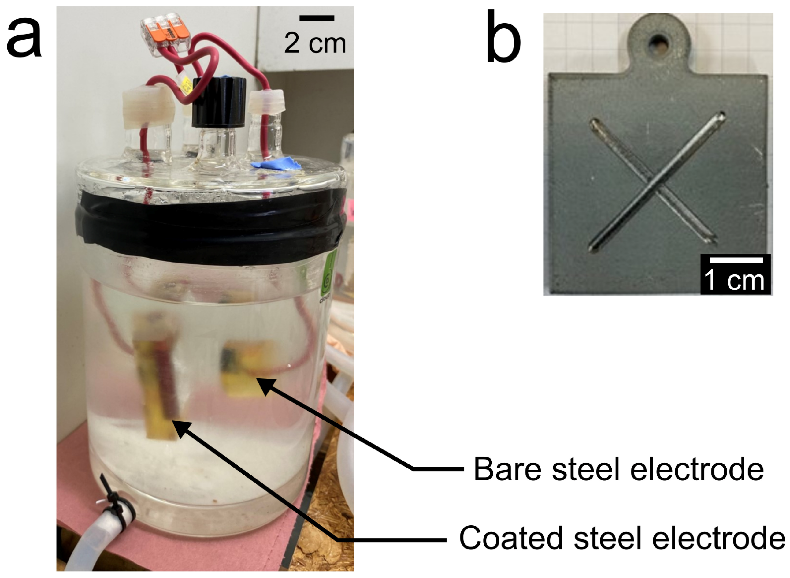
2.4. Electrochemical Set-Up and Methods

Solution 12 was used for all the experiments. Its composition is provided in Table 3. This solution mimics the pore water of the cement grout injected between the steel casing and the claystone formation. The pH was adjusted to 11.2 at 25 °C and checked 12 h later at 50 °C to be equal to the required value of 10.5 (Andra specifications). The main species present in Solution 12 is SO42−, with a total concentration of 3.36 × 10⁻² mol L−1.
All the electrochemical measurements were performed with a VSP potentiostat (BioLogic, Seyssinet-Pariset, France) using a platinum grid as the counter electrode and a Red/Rod reference electrode designed for high temperature measurements (Radiometer Analytical SAS, Lyon, France), characterized by a potential Eref = +0.173 V/SHE at 50 °C. In this paper, the potential values are, however, given with respect to the standard hydrogen electrode (V/SHE). The measurements were performed at a controlled temperature of 50 ± 2 °C in a double-wall glass cell.
Voltammetry was used preliminarily to study the electrochemical behavior and estimate the corrosion rate of the coatings using coated electrodes without a defect. The open circuit potential (OCP) of the studied electrode was monitored for 1 h, before a linear polarization resistance (LPR) measurement was performed at a potential scan rate of 0.1 mV s−1 in a potential range of OCP ± 10 mV. Finally, a polarization curve was acquired with the same scan rate, from a cathodic potential Ei = −0.150 V vs. OCP, up to an anodic potential corresponding to a maximum current density jlimit = 32.7 mA cm−2, and finally back to a potential sufficiently low to highlight any hysteresis effect (and thus depending on the studied electrode). This procedure proved adequate to highlight all the involved cathodic and anodic processes.
The corrosion study involved two types of 6-month experiments (Figure 1). The galvanic corrosion experiments were performed with a coated electrode and a bare steel electrode dimensioned to ensure a surface ratio between the anode (a priori the coated electrode, active area Sa) and the cathode (bare steel electrode, active area Sc) equal to Sa/Sc = 8.5. The two electrodes were facing each other in the solution, separated by a 4 cm distance. The corrosion study of the coated electrodes with a defect involved the same Sa/Sc ratio so that the results of both kinds of experiments could be compared. In this case, Sc is the surface of the defect, while Sa that of the coated part.
During the 6-month experiments, in between the electrochemical measurements, the electrochemical cells were stored in an oven at a controlled temperature of 50 ± 1 °C. Electrochemical measurements were carried out on the coated electrodes with a cross-shape defect and on the coated electrode of each galvanic couple after 1 h, after 1 week, and at the end of each month. The OCP of the coated electrodes with a defect and the mixed potential of the galvanic couples were first monitored during 1 h and the average value was recorded. The coated electrode of each galvanic couple was disconnected from the bare steel electrode to perform the measurements and obtain information specific to the coated sample. Its OCP was first monitored during 1 h, a time sufficient for the potential to stabilize, and an LPR measurement was then carried out as described previously. After this measurement, the bare steel electrode and the coated steel electrode were reconnected to each other. During the measurements performed on the coated electrode, the bare coated electrode was maintained at the previously measured galvanic potential with a second potentiostat.
The solution was not renewed during the 6-month experiments. However, its pH was controlled before each electrochemical measurement to check that no important evolution occurred. In any case, the pH was actually observed to be constant or not modified significantly (pH variation < ±0.1).

2.5. Characterization of Corrosion Products

The corrosion product layers covering the surface of the electrodes after the experiments were characterized by XRD, μ-RS, and SEM/EDS analysis. XRD analysis was performed with a D8 Advance diffractometer (Bruker AXS GmbH, Karlsruhe, Germany) using Cu-Kα radiation (weighted-average λ = 0.15418 nm), with Bragg–Brentano geometry in a 2θ range of 5° to 105°. The 2θ angle was varied by steps of 0.01° each 0.1 s. The diffracted signal was acquired using the LYNXEYE XE-T silicon strip detector. The ICDD-JCPDS-PDF-2 database (ICDD, Newtown Square, PA, USA) was used to identify the crystalline phases and the peaks were indexed according to the corresponding file.
μ-RS analysis was carried out with a LabRAM HR High-Resolution Raman spectrometer (Horiba, Tokyo, Japan) equipped with an Olympus BX41 microscope (Olympus, Tokyo, Japan) and a Peltier-based cooled charge-coupled device (CCD) detector. The analyzed zones were observed at a magnification of ×50. Spectra were acquired at room temperature via the LabSpec 6 software with a resolution of 0.4 cm−1. For the bare steel electrodes, the excitation was provided by an He-Ne laser (λ = 632.8 nm). Its power was 0.9 mW (10% of the maximal power) in order to prevent excessive heating of the analyzed compounds. For the coated steel electrodes, the excitation was provided by a near-IR (λ = 785 nm) laser diode at 100% of its power. In both cases, the acquisition time was equal to 180 s. As μ-RS provides a local analysis, various zones had to be analyzed, and the number of acquired spectra for a given sample was then ≥15.
SEM/EDS observation/analysis was performed with a FEI Quanta 200 Field Emission Gun (FEG) Environmental Scanning Electron Microscope (ESEM) equipped with an EDAX detector for chemical analysis (FEI Company, Hillsboro, OR, USA). The observation and analysis were carried out at 20 kV in a low vacuum (0.9 and 1.1 mbar of water vapor pressure) without any metallization. All the SEM images shown in this work were obtained using backscattered electrons in composition mode. For surface observation of the samples, no specific preparation was needed. For the cross-section observations, the cuts have been made with a diamond wire saw using a water-free cooling fluid. The obtained cross-sections were then abraded using SiC papers until grade 4000 (particle size 5 μm) with heptane as the cooling liquid, and mirror-polished using water-free diamond pastes (particle size 3 μm and 1 μm).

3. Results

3.1. Characterization of the Zn-Al Coatings before the Corrosion Experiments

First, it must be recalled that the Zn-Al coatings are two-phase Zn + Al systems because the solubility of Al in Zn is very low [31], as confirmed by previous XRD analysis presented in [7] for the Zn-15wt.%Al wire-arc-sprayed coating and confirmed by the post-experiment XRD analysis presented in Section 3.4.
The SEM surface observations of the three CS coatings presented in Figure 2 revealed the presence of incompletely deformed particles, i.e., particles that mainly keep their initial spherical shape. The average size of these particles, for all the coatings, is within the average powder size range, i.e., 25.7 to 31.3 µm (Table 1). Such incompletely deformed particles may lead to a high surface rugosity. The boundaries between the various particles are also clearly visible, suggesting that they could be a preferential path for the electrolyte infiltration.
The cross-section views presented in Figure 3 reveal the high heterogeneity of the chemical composition through the contrast between the various particles. The EDS analysis (Table 4) confirmed this observation. The heterogeneity of the composition is the highest for the Zn-5wt.%Al coating, where the darkest areas correspond to an Al content of 44.5 wt.% and the lightest areas to an Al content of 1.3 wt.%. The Zn-15wt.%Al and Zn-25wt.%Al coatings present a more homogeneous chemical composition. The only important difference between the Al contents in a given coating is observed between the dendrites (in black: 48.9 wt.% Al, zone 6) and the interdendritic areas (in grey: 10.3 wt.% Al, zone 5) of the Zn-25wt.%Al coating. Moreira et al. [32] have even observed the presence of pure Al and pure Zn zones in the dendritic structure of coatings with high Al content. This result is explained by the low miscibility of Zn and Al at room temperature [31]. The low magnification SEM images displayed in Figure 4 illustrate the heterogeneity of the Zn-5wt.%Al coating and the comparatively much more homogeneous distribution of the Al and Zn phases in the Zn-25wt.%Al coating.
The oxygen content, linked to the oxide content inside the coatings, is lower than 1% for both the Zn-5wt.%Al and Zn-25wt.%Al coatings and slightly higher, between 1.4 and 2.2 wt.%, for the Zn-15wt.%Al coating.
Hardness profiles, presented in Table 5, were only performed on the Zn-15wt.%Al and Zn-25wt.%Al coatings because the Zn-5wt.%Al coating was too heterogeneous. The hardness profile performed on a Zn-15wt.%Al wire-arc-sprayed (WA) coating was added for comparison (see [7] for details about the preparation of such coatings). The hardness values were higher for the CS coatings than those obtained for the WA coating. This result can be explained by the smaller ratio of porosities in the CS coating (as observed on the SEM cross-sections) and also by the hardening taking place during the coating elaboration.
The Zn-25wt.%Al coating is characterized by the highest hardness. This can be attributed to the highest Al content because aluminum has a hardness of ~167 HV, significantly larger than that of pure zinc, i.e., about 70 HV for the bulk or 55 HV for electrodeposited Zn coating [33]. It must then be noted that the Zn-Al coatings have a hardness smaller than that of both bulk metals. This lower hardness value could be due to the lack of cohesion between the splats and the presence of porosities.
The adhesion strength was determined for each coating. In each case, adhesive ruptures were observed and the adhesion strength could then be estimated for each coating. The obtained ultimate tensile strength was 32 MPa for the Zn-15wt.%Al CS coating, which is higher than the value of 23 MPa previously found for Zn-15wt.%Al WA coating [7]. According to the literature [34], a higher adhesion strength was indeed expected for the CS coating with respect to the WA coating because CS coatings result from the plastic deformation of the impacting particles. The ultimate tensile strength was the smallest (17 MPa) for the Zn-5wt.%Al CS coating, which could be linked to the observed important heterogeneity in the composition. Finally, the highest ultimate tensile strength (38 MPa) was obtained with the Zn-25wt.%Al CS coating.

3.2. Corrosion Behavior of Zn-Al Coatings

All the measured electrochemical parameters are reported in Table 6. First, the electrochemical behaviors of the Zn-15wt.%Al CS- and Zn-15wt.%Al WA-coated electrodes were compared using voltammetry. The corresponding polarization curves are presented in Figure 5.
Both curves are similar, with a large diffusion plateau in the cathodic part, which corresponds to the limiting current density associated with the dissolved O2 reduction. The corrosion potential Ecor of the Zn-15wt.%Al WA-coated sample is equal to −0.79 V/SHE and thus smaller than that of the Zn-15wt.%Al CS-coated sample, equal to −0.75 V/SHE. The corrosion current density jcor can be estimated via the extrapolation of the diffusion plateau up to Ecor, thus assuming that the cathodic current density jc at Ecor corresponds to the limiting current density. A higher value is then observed for the CS coating, jcor = 11.5 µA/cm−2, than for the WA coating, jcor = 4.5 µA cm−2. The higher corrosion current density observed for the CS coating could be explained by the higher reactivity of the surface of the coating. The increased reactivity of the CS coating cannot be explained by an increased surface roughness as this parameter was similar for both the CS and WA coatings. It could then be due to the very important plastic deformation of particles involved in the cold-spraying process, which is known to have significant effects on both anodic [35] and cathodic processes [36]. A drastic increase in the current density in the anodic domain is finally observed, indicating the active dissolution of the coating. In the reverse scan, an important hysteresis is observed, which can be attributed to the previous important degradation of the surface, which induces an increase in the active area.
Secondly, the various Zn-Al cold-sprayed coated electrodes were compared (Figure 6). The OCP vs. time curves recorded during the first hour of immersion are displayed in Figure 6a. It can be seen that the OCP is rather stable in each case all along the one hour of monitoring. The OCP values of the Zn-5wt.%Al and Zn-15wt.%Al coatings are similar, with an average value of −0.8 V/SHE. This value is 450 mV lower than the average OCP of the steel substrate. For the Zn-25wt.%Al coating, an average OCP value about −1.2 V/SHE is obtained. The difference with the OCP of steel is in this case much higher and reaches 850 mV. This important difference between the steel and the coating could induce a high decrease in the potential of the steel substrate and induce significant hydrogen formation, thus possibly increasing the risk of hydrogen embrittlement.
The polarization curves of the different coated electrodes are displayed in Figure 6b and compared with that of a P285NH carbon steel electrode. The values of the corrosion potentials are consistent with the OCP values reported above, with the lowest Ecor corresponding to the Zn-25wt.%Al coating (−1.11 V/SHE), similar Ecor values observed for the Zn-5wt.%Al and Zn-15wt.%Al coatings, i.e., −0.79 V/SHE and −0.75 V/SHE, respectively, and a much higher value of −0.32 V/SHE for carbon steel.
The electrochemical behavior of the Zn-25wt.%Al coated electrode is clearly different from that of the two other coated electrodes. First, there is no diffusion plateau in the cathodic part of the curve, which indicates that the main cathodic reaction is water reduction; in other words, the hydrogen evolution reaction (HER). Secondly, a large plateau is seen in the anodic domain. This may correspond to a pseudo-passivation phenomenon, not to a “true” passivation, as the associated anodic current density is rather important, namely higher than the corrosion current density measured for the two other coated electrodes. The anodic current decreases slightly after −0.9 V/SHE but finally increases drastically once a potential of −0.64 V/SHE is reached. This may correspond to the breakdown of the pseudo-passive layer and the beginning of a pitting corrosion process. In this case, the hysteresis observed when reversing the potential scan could correspond to the evolution of the electrode before repassivation of the metal inside the pits. The Zn-5wt.%Al-coated electrode is characterized by a behavior similar to that of the Zn-15wt.%Al-coated electrode, already described above (Figure 5). For carbon steel, a diffusion plateau can be seen in the cathodic part, as for the Zn-5wt.%Al- and Zn-15wt.%Al-coated electrodes and with a similar limiting current density. The corrosion current density jcor was determined for each coating as described above. For the Zn-25wt.%Al coating, in the absence of a diffusion plateau, the corrosion current density was obtained by extrapolating the cathodic Tafel line up to Ecor, as illustrated by the black dashed lines in Figure 6b. As already visible on the polarization curves, jcor proved the highest for Zn-25wt.%Al (57 µA cm−2), then Zn-15wt.%Al (11.5 µA cm−2) and finally, Zn-5wt.%Al (3.6 µA cm−2).

3.3. Six Months of Corrosion Experiments

The evolutions of the potential of the galvanic couples and coated electrodes with a cross-shape defect are presented in Figure 7a. For each coating, the evolution is similar for both configurations, i.e., the potential tends to increase with time.
In the case of the Zn-15wt.%Al coating, the potential of the system was at the beginning (0–1 week) comprised between −0.82 V/SHE and −0.75 V/SHE, i.e., similar to the OCP previously measured for a non-defective coated electrode. At the end of the 6-month experiment, both systems had reached the same value of −0.61 V/SHE. For the Zn-5wt.%Al coating, the initial potential values, comprised between −0.83 V/SHE and −0.787 V/SHE, were similar to those measured for the Zn-15wt.%Al systems. At the end the 6-month experiment, the mixed potential of the galvanic couple had increased up to −0.53 V/SHE, while the potential of the coated electrode with a defect remained lower, at −0.65 V/SHE. These two values, however, led to an average of −0.59 V/SHE, a value once again similar to that measured for the Zn-15wt.%Al system. This confirms the results obtained after 1 h of immersion with the non-defective electrodes, i.e., the Zn-5wt.%Al and Zn-15wt.%Al coatings have similar electrochemical behaviors.
In contrast, the potential values obtained with the Zn-25wt.%Al coatings differ importantly from both the OCP and Ecor values obtained with a non-defective electrode. They are much higher and actually similar to those obtained with the Zn-5wt.%Al and Zn-15wt.%Al coatings. This result can be explained by looking at the polarization curves displayed in Figure 6b. The mixed potential of the galvanic couple, and similarly that of the coated electrode with a defect, can be predicted qualitatively from the polarization curves of the coated electrode and bare steel electrode. The extrapolation of the cathodic part of the steel polarization curve can only intersect the anodic part of the curves of the Zn-5wt.%Al and Zn-15wt.%Al alloys close to the corrosion potential of these alloys because of the very sharp increase in the current in the anodic region. In contrast, because of the large pseudo-passivation plateau typical of the Zn-25wt.%Al alloy, the intersection between the cathodic part of the steel polarization curve and that of the anodic part of the Zn-25wt.%Al alloy curve may be found in a wide potential range. It may depend on the Sa/Sc ratio and could even be located above the breakdown potential Eb, observed at −0.64 V/SHE. Actually, the mixed potential of the Zn-25wt.%Al systems increases from about −0.8 V/SHE to stabilize about −0.6/−0.65 V/SHE, i.e., around the breakdown potential, after two months.
The evolutions of the Rp values for the coated electrodes of the galvanic couples and the coated electrodes with a defect are presented in Figure 7b. At the beginning (0–1 week), whatever the configuration and whatever the composition of the coating, the polarization resistance is below 10,000 Ω cm2, with a minimum is observed in each case after 1 week and is comprised between 2000 Ω cm2 and 4000 Ω cm2. The Rp increases with time afterwards, remaining somewhat stable after about 3 months. The highest values are those reached by the Zn-15wt.%Al- and Zn-25wt.%Al-coated electrodes with a defect, with the final Rp values of 32,000 Ω cm2 and 28,000 Ω cm2, respectively. For the corresponding coatings of the galvanic couples, it can be observed that the Rp value of the Zn-25wt.%Al-coated electrode oscillated around 20,000 Ω cm2 for the last 3 months, while the Rp of the Zn-15wt.%Al-coated electrode finally reached this same value of 20,000 Ω cm2 at the end of the experiment. All along the experiment, the average Rp value measured for the Zn-5wt.%Al-coated electrodes is the smallest.
In conclusion, no inversion of polarity was observed and all the coatings remained active and ensured a galvanic protection of the bare steel surface, whether this surface was that of a defect in the coating or that of a steel electrode coupled with the coated electrode. The polarization resistance of the coated electrodes increased with time in any case, which can be attributed to the growth of a corrosion product layer on the Zn-Al alloy surface. The Zn-15wt.%Al and Zn-25wt.%Al coatings are characterized by higher Rp values and can then be considered as more efficient than the Zn-5wt.%Al coating because they should provide galvanic protection for a longer time.

3.4. Characterization of the Corrosion Products after an Extended Immersion Duration

Figure 8 presents photographs of the coated electrodes, with or without a defect, after the 6-month corrosion experiments. The surface of the coatings is covered with white corrosion products. For both Zn-15wt.%Al-coated electrodes, these products form a rather homogeneous layer that covers the overall surface of the coating. The cross-shape defect remains clearly visible, i.e., the corrosion products of the Zn-15wt.%Al alloy did not extend over the steel surface.
For the other electrodes, the corrosion products are not homogenously distributed over the surface of the coating. For the Zn-25wt.%Al alloy, this can be explained by the pseudo-passive behavior, which favors localized corrosion. As noted previously, the mixed potential value was in this case similar to the breakdown potential observed on the polarization curve. For the Zn-5wt.%Al coatings, this phenomenon can be attributed to the important heterogeneity of the composition. It can also be noted that the amount of corrosion products present on the surface of the coating with a defect is more important in the vicinity of the defect, which shows that the galvanic coupling with steel significantly increased the corrosion rate of the Zn-5wt.%Al alloy. As a result, the cross-shape defect is hardly visible.
Visual observations of the steel surface, whether those of cross-shape defects or those of coupled bare steel electrodes, did not evidence any rust formation or corrosion damage, confirming that all the coatings ensured an efficient galvanic protection during the 6-month experiments.
XRD analysis (Figure 9) demonstrated that the corrosion products were the same whatever the coating. The main ones were zinc hydroxysulfates, and more precisely, two hydrated phases, Zn4SO4(OH)6∙1H2O and Zn4SO4(OH)6∙3H2O. This is consistent with the composition of Solution 12, where sulfate is the main species (Table 3). Zincite, i.e., zinc oxide ZnO, was also identified in each case. In addition, the two phases that compose the coatings, i.e., Zn and Al, were also detected. However, the intensity of their diffraction peaks is much smaller for the Zn-15wt.%Al coating. This is consistent with the photographs shown in Figure 7, where the corrosion products are seen to cover the whole surface for the Zn-15wt.%Al-coated electrode while, conversely, large bare metal areas are visible for both the Zn-5wt.%Al and Zn-25wt.%Al-coated electrodes.
Raman analysis led to the same kind of spectrum in each case, and one example is displayed in Figure 10. Two spectral signatures were obtained, confirming the presence of two main corrosion products.
The first typical spectrum is that corresponding to area 1 in Figure 9. The corresponding compound is characterized by two main peaks at 144 cm−1 and 675 cm−1, and three smaller peaks at 218 cm−1, 363 cm−1 and 413 cm−1. It could not be identified using the available relevant published data. This compound is also present in area 2, together with a second corrosion product. This second compound is characterized by four main Raman peaks located at 383 cm−1, 440 cm−1, 608 cm−1 and 972 cm−1. A similar spectrum was already observed and attributed to Zn-hydroxysulfate [37]. In conclusion, Raman analysis confirms the presence of Zn hydroxysulfate(s) on the surface of each coating, in agreement with the XRD analysis.
The results of the SEM/EDS surface observations and analysis are synthesized in Figure 11 and Table 7.
Figure 11 shows a representative SEM image that reveals two kinds of morphologies, i.e., large platelets and clusters of smaller particles. EDS analysis of the large platelets revealed that they were mainly composed of Zn (62 to 66 wt.%) and O (21 to 27 wt.%), and they always contained a significant amount of S (1.8 to 3.6 wt.%). Conversely, the Al content was very low (0 to 0.6 wt.%), which indicates that the platelets correspond to the Zn-hydroxysulfate(s) identified by XRD and µ-RS. The clusters of smaller particles were also mainly composed of Zn (~81 wt.%) and oxygen (~11 wt.%), with a very low amount of S (~0.5 wt.%), and once again, a very low amount of Al (~0.5 wt.%). This result confirms that a small amount of ZnO has also formed, as revealed by XRD.
SEM/EDS analysis thus definitively confirms the predominance of Zn corrosion products, which demonstrates that the preferential dissolution of the Zn phase took place. The selective dissolution of the Zn phase could be due to the passivation of the Al phase present in the coating, i.e., the formation of a thin blocking film as suggested by Vu et al. [38]. Al is less noble than Zn and should be oxidized preferentially [39], and its passivation thus explains the selective dissolution of Zn. This passive film or blocking thin layer was more likely too thin and/or covered with Zn corrosion products and could not be detected, neither by XRD and µRS surface analysis nor via SEM/EDS analysis.
Cross-sections were also characterized by SEM/EDS analysis to study the possible effects of the infiltration of the solution in the poral network of the coatings. Similar trends were observed whatever the Al content and, as examples, the Zn-15wt.%Al coating was selected to illustrate the progression of these effects over time (Figure 12) and the Zn-25wt.%Al coating was selected to compare the coupled coated electrode with the coated electrode having a cross-shape defect (Figure 13).
The cross-section observations of the Zn-15wt.%Al coating after 1 and 6 months of galvanic coupling experiments revealed oxidation of the boundaries of the particles constituting the coating (Figure 12b,d). It is also clearly seen that the amount of corrosion products (in grey) around the particles (in white) is more important after 6 months than it was after only 1 month. This phenomenon is due to the infiltration of the electrolyte inside the coating, as observed in the previous work [7]. The effects are less important here for the CS coating than for the WA coating. This can be quantified by comparing the swelling of the coating in both cases. It is 8% after 1 month and 27% after 6 months for the CS coating studied here, while it was already equal to 13% after only 3 days for the WA coating, and 50% after 6 months [7]. However, as seen in Figure 12c, the phenomenon induced cracks in the coating after the 6-month experiment.
The cross-section observations of the Zn-25wt.%Al coating after 6 months of galvanic coupling (Figure 13a) or with a cross defect (Figure 13b,c) also revealed an electrolyte infiltration, which led to the oxidation of the particle boundaries. For the two types of experiments after 6 months of immersion, the coating presented some cracks due to the internal growth of the corrosion product layer around the particles. For the coated electrode with a cross-shape defect, the mechanical damages to the coating were more important near the defective area (Figure 13c) than far from it (Figure 13b). The corrosion of the coating is more severe near the defect, because of the stronger galvanic effect, and, moreover, the electrolyte can also penetrate inside the coating through its edge, i.e., parallelly to the electrode surface.
A SEM cross-section of the Zn-5wt.%Al coating after 6 months of galvanic coupling is displayed in Figure 14. This image can be compared with those already shown for the other coatings, i.e., Figure 12c and Figure 13a for the Zn-15wt.%Al and Zn-25wt.%Al coatings, respectively. As for both other coatings, the cross-section appears homogeneous, i.e., the infiltration of the electrolyte and its effects have impacted the entire coating thickness. A long crack parallel to the steel/coating interface is also clearly visible. Moreover, this image was taken in a region where a heap of white corrosion products was present. It illustrates the non-uniformity of the corrosion process. The corrosion products (in dark grey) are found inside a locally strongly corroded area, where the remaining coating thickness is only half that of the average coating thickness.
Finally, to compare the kinetics of the infiltration through the three coatings, shorter galvanic coupling experiments of 6 days were performed. The corresponding cross-section images are shown in Figure 15. The infiltration phenomenon seems to be faster in the Zn-15wt.%Al coating, with a 250 µm thick zone impacted by infiltration. For the Zn-5wt.%Al and Zn-25wt.%Al coatings, the impacted thickness was lower, with 90 and 110 µm, respectively.

4. Discussion

In the first study of Zn-based sacrificial coatings for protection against the corrosion of the carbon steel containers in the frame of the French project for deep geological nuclear waste disposal, the efficiency of Zn-Al alloys was established [7]. The considered electrolyte was then Solution 15, which mimics the pore solution of the cement grout modified by the influence of the surrounding claystone. The electrolyte considered for the present study was Solution 12, which mimics the initial pore water of the cement grout. The compositions of these solutions are different and Solution 15 can be considered as more aggressive because it contains sulfide species (3.1 × 10⁻⁵ mol L−1) and a higher amount of chloride ions (3.5 × 10⁻² mol L−1 [7] vs. 1.0 × 10⁻⁵ mol L−1 for Solution 12). The present study shows that Zn-Al coatings can be efficient in Solution 12 too, whatever the considered composition (5, 15 or 25 wt.% Al), i.e., during the earlier stages of nuclear waste storage.
In any case, during the 6-month corrosion experiments, all the Zn-Al coatings ensured efficient galvanic protection of the carbon steel. The polarization resistance of the coated electrodes increased with time because of the formation on the surface of the coating of a somewhat protective corrosion product layer composed of zinc hydroxysulfates and ZnO. SEM/EDS observations and analysis confirmed that the corrosion products only contained a very low amount of Al, i.e., were Zn corrosion products. These results show that the Zn phase dissolved selectively while the Al phase more likely passivated. In the previous study carried out in the more aggressive Solution 15, a Zn-Al hydroxysulfate was also formed [7], which showed that both the Zn and Al phases dissolved. In Solution 15, Al may not passivate and thus may remain active. Note that the previous study [7] was carried out at a higher temperature, 80 °C instead of 50 °C, which may also explain part of the observed differences.
In the present study, the growth and evolution with time of the corrosion product layer was not addressed, and the layers were only characterized at the end of the corrosion experiments. More detailed works, in particular dealing with atmospheric corrosion of zinc in marine atmospheres, can, however, be used as references. In marine tropical atmospheres, it was, for instance, shown that the corrosion process finally led to a three-layer structure including, from the metal surface to the environment, Zn hydroxychloride, sodium-zinc hydroxysulfate, zinc hydroxycarbonates and ZnO [40]. In Solution 12, where sulfate species predominate over chloride and carbonate species, it is noticeable that only zinc hydroxysulfates and ZnO were formed.
The Zn-5wt.%Al and Zn-25wt.%Al coatings exhibited specific weak points. The Zn-5wt.%Al coating was characterized by a highly heterogeneous composition that favored localized corrosion (Figure 8 and Figure 14). Actually, it appeared that the powder used for the cold-spraying process itself had a highly heterogeneous composition. Moreover, after the 6-month corrosion study, the Zn-5wt.%Al coatings had the lowest Rp values, i.e., the highest corrosion rate and thus the shortest lifetime.
The Zn-25wt.%Al coating was characterized, as revealed by voltammetry, by a “pseudo-passive” behavior that also favored localized corrosion (Figure 8). It must be remembered that, in any case, the coating is a two-phase Zn + Al system (see Figure 9, for instance). At low Al contents, as observed for the Zn-5wt.%Al and Zn-15wt.%Al coatings, the electrochemical behavior is quite similar to that of pure zinc, with an active behavior. With 25 wt.% Al, the electrochemical behavior is somehow intermediate between that of Al and that of Zn, with a trend toward passivation due to Al that gives rise to the observed “pseudo-passive” plateau, and the active dissolution of Zn that explains the high measured jcor value.
Moreover, the important difference between the OCP of the Zn-25wt.%Al coating and that of carbon steel in Solution 12 at 50 °C could induce important production of hydrogen on the steel surface and promote hydrogen embrittlement. In the present study, the mixed potential of the steel/Zn-25wt.%Al galvanic couple increased from −0.8 V/SHE to −0.6 V/SHE with time, thus stabilizing around the breakdown potential of the Zn-25%Al coating pseudo-passive layer (Eb = −0.64 V/SHE), above which localized corrosion becomes active.
Consequently, the Zn-15wt.%Al coating exhibited the best performance according to both the electrochemical (active behavior in the anodic domain) and corrosion (highest Rp values and uniform corrosion) studies. The infiltration of the electrolyte in the poral network of the coating, though less rapid for the CS coating than for the WA coating, was however the fastest, if compared with the Zn-5wt.%Al and Zn-25wt.%Al CS coatings.
After the 6-month corrosion study, the effects of the infiltration, leading to the formation of corrosion products around the Zn-Al particles inside the coating, were observed in any case along the whole thickness of the coatings, whatever their composition. For the coated electrodes without a defect, coupled with a bare steel electrode, this infiltration phenomenon induced important swelling of the coating and the formation of cracks.
For the coated electrodes with a cross-shaped defect, which are more representative of the real case, the cracks were mainly located in the coating close to the defects where the infiltration of electrolyte is facilitated and the corrosion rate increased by the galvanic coupling with the steel in the defect.

5. Conclusions

Zn-Al cold-sprayed coatings were considered as an anticorrosion system for the carbon steel containers of the deep geological disposal envisioned in France for the management of nuclear waste. The corrosion study was carried out in a representative solution at 50 °C. The three studied compositions, i.e., Zn-5wt.%Al, Zn-15wt.%Al and Zn-25wt.%Al, proved efficient all along the 6-month corrosion study. The Zn-5wt.%Al coating was, however, characterized by the important heterogeneity of the chemical composition, which induced localized corrosion. Moreover, its Rp values were the lowest. The Zn-25wt.%Al coating was characterized by a “pseudo-passive” behavior, which could present a risk of the loss of sacrificial properties. In addition, its corrosion potential was very low and the risk that it could induce a hydrogen embrittlement of the protected steel cannot be discarded. Zn-15wt.%Al appears to be the best composition for the considered application. Unfortunately, infiltration of the electrolyte took place, inducing the oxidation of the particles that constitute the coating, an important swelling of the coating and the formation of cracks. This phenomenon was less important for the cold-sprayed coatings than it was for wire-arc-sprayed coatings [7], but further work is still required to limit it. The envisioned strategy is to add ceramic particles into the powder feedstock to increase, via a peening effect, the compacity of the cold-sprayed coating.

Author Contributions

Conceptualization, J.C., R.S., G.C., C.V., F.G. and P.R.; methodology, J.C., R.S., G.C., E.C., C.V., F.G. and P.R.; validation, J.C., G.C., V.M., D.C. and P.R.; formal analysis, A.M., J.C., G.C., E.C. and P.R.; investigation, A.M., J.C., C.V., F.G., R.S., E.C. and P.R.; writing—original draft preparation, A.M., J.C., C.V. and P.R.; writing—review and editing, J.C., G.C., V.M., D.C., E.C. and P.R.; visualization, A.M., E.C. and P.R.; supervision, J.C., G.C., R.S. and P.R.; project administration, P.R., J.C., G.C. and V.M.; funding acquisition, G.C., V.M. and D.C. All authors have read and agreed to the published version of the manuscript.

Funding

This research received no external funding.

Institutional Review Board Statement

Not applicable.

Informed Consent Statement

Not applicable.

Data Availability Statement

The data presented in this study are available on request from the corresponding author.

Acknowledgments

This study was financially supported by the French National Radioactive Waste Management Agency (Andra). The authors would like to thank M. Lemaire and B. Péraudeau for their help during the preparation of the experiments, C. Rébéré for the additional µ-XRF analysis and S. Cohendoz for the microhardness profile measurements.

Conflicts of Interest

The authors declare no conflicts of interest.

References

  1. Dupuis, M.C.; Gonnot, F.M. The Cigéo Project: Meuse/Haute-Marne Reversible Geological Disposal Facility for Radioactive Waste; Reference 504va; Andra: Châtenay-Malabry, France, 2013. [Google Scholar]
  2. Rincón, O.T.; Rincón, A.; Sánchez, M.; Romero, N.; Salas, O.; Delgado, R.; López, B.; Uruchurtu, J.; Marroco, M.; Panossian, Z. Evaluating Zn, Al and Al–Zn coatings on carbon steel in a special atmosphere. Construct. Buil. Mater. 2009, 23, 1465–1471. [Google Scholar] [CrossRef]
  3. Büteführ, M. Zinc-Aluminium-Coatings as Corrosion Protection for Steel. Mater. Corros. 2007, 58, 721–726. [Google Scholar] [CrossRef]
  4. Kaewmaneekul, T.; Lothongkum, G. Effect of aluminium on the passivation of zinc–aluminium alloys in artificial seawater at 80 °C. Corros. Sci. 2013, 66, 67–77. [Google Scholar] [CrossRef]
  5. Katayama, H.; Kuroda, S. Long-term atmospheric corrosion properties of thermally sprayed Zn, Al and Zn–Al coatings exposed in a coastal area. Corros. Sci. 2013, 76, 35–41. [Google Scholar] [CrossRef]
  6. Lee, H.-S.; Singh, J.K.; Ismail, M.A.; Bhattacharya, C.; Seikh, A.H.; Alharthi, N.; Hussain, R.R. Corrosion mechanism and kinetics of Al-Zn coating deposited by arc thermal spraying process in saline solution at prolong exposure periods. Sci. Rep. 2019, 9, 3399. [Google Scholar] [CrossRef]
  7. Martin, A.; Texier-Mandoki, N.; Crusset, D.; Sabot, R.; Creus, J.; Refait, P. Corrosion Behavior and Sacrificial Properties of Zn and Zn-Al Coatings in Conditions Simulating Deep Geological Disposal of Radioactive Waste at 80 °C. Coatings 2022, 12, 1044. [Google Scholar] [CrossRef]
  8. Glass, G.K.; Ashworth, V. The corrosion behavior of the zinc-mild steel galvanic cell in hot sodium bicarbonate solution. Corros. Sci. 1985, 25, 971–983. [Google Scholar] [CrossRef]
  9. Fraunhofer, J.A.; Lubinski, A.T. Polarity reversal in the zinc-mild steel couple. Corros. Sci. 1974, 14, 225–232. [Google Scholar] [CrossRef]
  10. Refait, P.; Jeannin, M.; François, E.; Sabot, R.; Grolleau, A.-M. Galvanic corrosion in marine environments: Effects associated with the inversion of polarity of Zn/carbon steel couples. Mater. Corros. 2019, 70, 950–961. [Google Scholar] [CrossRef]
  11. Schmidt, T.; Assadi, H.; Gärtner, F.; Richter, H.; Stoltenhoff, T.; Kreye, H.; Klassen, T. From Particle Acceleration to Impact and Bonding in Cold Spraying. J. Therm. Spray Technol. 2009, 18, 794–808. [Google Scholar] [CrossRef]
  12. Azarmi, A.; Sevostianov, I. Comparative micromechanical analysis of alloys 625 coatings deposited by air plasma spraying, wire arc spraying, and cold spraying technologies. Mech. Mater. 2020, 144, 103345. [Google Scholar] [CrossRef]
  13. Assadi, H.; Gartner, F.; Stoltenhoff, T.; Kreye, H. Bonding mechanism in cold gas spraying. Acta Mater. 2003, 51, 4379–4394. [Google Scholar] [CrossRef]
  14. Raoelison, R.N.; Verdy, C.; Liao, H. Cold gas dynamic spray additive manufacturing today: Deposit possibilities technological solutions and viable applications. Mater. Des. 2017, 133, 266–287. [Google Scholar] [CrossRef]
  15. Van Steenkiste, T.H.; Smith, J.R.; Teets, R.E. Aluminum coatings via kinetic spray with relatively large powder particles. Surf. Coat. Technol. 2002, 154, 237–252. [Google Scholar] [CrossRef]
  16. Alkhimov, A.P.; Kosarev, V.F.; Papyrin, A.N. A Method of Cold Gas-Dynamic Deposition. Sov. Phys. Dokl. 1990, 35, 1047–1049. [Google Scholar]
  17. Champagne, V.; Helfritch, D. The unique abilities of cold spray deposition. Int. Mater. Rev. 2016, 61, 437–455. [Google Scholar] [CrossRef]
  18. Lupoi, R.; O’Neill, W. Deposition of metallic coatings on polymer surfaces using cold spray. Surf. Coat. Technol. 2010, 205, 2167–2173. [Google Scholar] [CrossRef]
  19. Wüstefeld, C.; Rafaja, D.; Motylenko, M.; Ullrich, C.; Drehmann, R.; Grund, T.; Lampke, T.; Wielage, B. Local heteroepitaxy as an adhesion mechanism in aluminium coatings cold gas sprayed on AlN substrates. Acta Mater. 2017, 128, 418–427. [Google Scholar] [CrossRef]
  20. Drehmann, R.; Grund, T.; Lampke, T.; Wielage, B.; Wüstefeld, C.; Motylenko, M.; Schreiber, G.; Rafaja, D. Investigation of the Bonding Mechanisms of Al Coatings on Ceramic Substrates Deposited by Cold Gas Spraying and Magnetron Sputtering. In Proceedings of the International Thermal Spray Conference, Long Beach, CA, USA, 11–14 May 2015; pp. 544–552. [Google Scholar]
  21. Li, W.Y.; Cao, C.C.; Yin, S. Solid-state cold spraying of Ti and its alloys: A literature review. Prog. Mater. Sci. 2020, 110, 100633. [Google Scholar] [CrossRef]
  22. Assadi, H.; Kreye, H.; Gärtner, F.; Klassen, T. Cold spraying—A materials perspective. Acta Mater. 2016, 116, 382–407. [Google Scholar] [CrossRef]
  23. Hassani-Gangaraj, M.; Veysset, D.; Nelson, K.A.; Schuh, C.A. In-situ observations of single micro-particle impact bonding. Scr. Mater. 2018, 145, 9–13. [Google Scholar] [CrossRef]
  24. Hassani-Gangaraj, M.; Veysset, D.; Champagne, V.K.; Nelson, K.A.; Schuh, C.A. Adiabatic shear instability is not necessary for adhesion in cold spray, Acta. Mater. 2018, 158, 430–439. [Google Scholar]
  25. Grujicic, M.; Zhao, C.L.; DeRosset, W.S.; Helfritch, D. Adiabatic shear instability-based mechanism for particles/substrate bonding in the cold-gas dynamic-spray process. Mater. Des. 2004, 25, 681–688. [Google Scholar] [CrossRef]
  26. Saleh, M.; Luzin, V.; Spencer, K. Analysis of the residual stress and bonding mechanism in the cold spray technique using experimental and numerical methods. Surf. Coat. Technol. 2014, 252, 15–28. [Google Scholar] [CrossRef]
  27. Panossian, Z.; Mariaca, L.; Morcillo, M.; Flores, S.; Rocha, J.; Pena, J.J.; Herrera, F.; Corvo, F.; Sanchez, M.; Rincon, O.T.; et al. Steel cathodic protection afforded by zinc, aluminium and zinc/aluminium alloy coatings in the atmosphere. Surf. Coat. Technol. 2005, 190, 244–248. [Google Scholar] [CrossRef]
  28. Yadav, A.P.; Katayama, H.; Noda, K.; Masuda, H.; Nishikata, A.; Tsuru, T. Effect of Al on the galvanic ability of Zn–Al coating under thin layer of electrolyte. Electrochim. Acta 2007, 52, 2411–2422. [Google Scholar] [CrossRef]
  29. Necib, S.; Bumbieler, F.; Duret-Thual, C.; Bulidon, N.; Crusset, D.; Combrade, P. Assessment of the resistance to environmentally assisted cracking (EAC) of C-steel casing and overpack in the COx claystone. Corros. Eng. Sci. Technol. 2017, 52, 95–100. [Google Scholar] [CrossRef]
  30. ASTM C633-01; Standard Test Method for Adhesion or Cohesion Strength of Thermal Spray Coatings. ASTM International: West Conshohocken, PA, USA, 2008.
  31. Drapala, J.; Kostiukova, G.; Losertova, M. Contribution to the aluminum–tin–zinc ternary system. IOP Conf. Ser. Mater. Sci. Eng. 2017, 266, 012002. [Google Scholar] [CrossRef]
  32. Moreira, A.R.; Panossian, Z.; Camargo, P.L.; Ferreira Moreira, M.; Da Silva, I.C.; Ribeiro de Carvalho, J.E. Zn/55Al coating microstructure and corrosion mechanism. Corros. Sci. 2006, 48, 564–576. [Google Scholar] [CrossRef]
  33. Exbrayat, L.; Steyer, P.; Rébéré, C.; Berziou, C.; Savall, C.; Ayrault, P.; Tertre, E.; Joly-Pottuz, G.L.; Creus, J. Electrodeposition of zinc–ceria nanocomposite coatings in alkaline bath. J. Solid State Electrochem. 2014, 18, 223–233. [Google Scholar] [CrossRef]
  34. Aubanel, L.; Delloro, F. Tribological behavior of steel-based composite coatings produced by cold spray. Surf. Coat. Technol. 2023, 470, 129815. [Google Scholar] [CrossRef]
  35. Akiyama, E.; Zhang, Z.; Watanabe, Y.; Tsusaki, K. Effects of severe plastic deformation on the corrosion behavior of aluminum alloys. J. Solid State Electrochem. 2009, 13, 277–282. [Google Scholar] [CrossRef]
  36. Cui, Z.; Liu, Z.; Wang, L.; Du, C.; Wang, X. Effect of plastic deformation on the electrochemical and stress corrosion cracking behavior of X70 steel in near-neutral pH environment. Mater. Sci. Eng. A 2016, 677, 259–273. [Google Scholar] [CrossRef]
  37. Cachet, C.; Ganne, F.; Joiret, S.; Maurin, G.; Petitjean, J.; Vivier, V.; Wiart, R. EIS investigation of zinc dissolution in aerated sulphate medium. Part II: Zinc coatings. Electrochim. Acta 2002, 47, 3409–3422. [Google Scholar] [CrossRef]
  38. Vu, T.N.; Mokaddem, M.; Volovitch, P.; Ogle, K. The anodic dissolution of zinc and zinc alloys in alkaline solution. II. Al and Zn partial dissolution from 5% Al–Zn coatings. Electrochim. Acta 2012, 74, 130–138. [Google Scholar] [CrossRef]
  39. Vu, T.N.; Volovitch, P.; Ogle, K. The effect of pH on the selective dissolution of Zn and Al from Zn–Al coatings on steel. Corros. Sci. 2013, 67, 42–49. [Google Scholar] [CrossRef]
  40. Cui, Z.; Li, X.; Xiao, K.; Dong, C.; Liu, Z.; Wang, L. Corrosion behavior of field-exposed zinc in a tropical marine atmosphere. Corrosion 2014, 70, 731–748. [Google Scholar] [CrossRef] [PubMed]
Figure 1. (a) Electrochemical set-up used for 6-month galvanic corrosion experiments and (b) coated electrode with a cross-shape defect.
Coatings 14 00261 g001
Figure 2. SEM observations of the surface of the cold-sprayed (a) Zn-5wt.%Al, (b) Zn-15wt.%Al and (c) Zn-25wt.%Al coatings. The diameter of some incompletely deformed particles is shown in red.
Coatings 14 00261 g002
Figure 3. SEM observations (cross-sections) of the cold-sprayed (a) Zn-5wt.%Al, (b) Zn-15wt.%Al and (c) Zn-25wt.%Al coatings.
Coatings 14 00261 g003
Figure 4. SEM observations at low magnification of cross-sections of the cold-sprayed (a) Zn-5wt.%Al and (b) Zn-25wt.%Al coatings.
Coatings 14 00261 g004
Figure 5. Polarization curves obtained with Zn-15wt.%Al-coated carbon steel electrodes elaborated by wire arc spraying (WA) and cold spraying (CS) after 1 h of immersion.
Coatings 14 00261 g005
Figure 6. (a) OCP curves obtained during a 1 h immersion period with Zn-5wt.%Al, Zn-15wt.%Al and Zn-25wt.%Al CS-coated carbon steel electrodes and (b) corresponding polarization curves acquired right after the 1 h immersion period. In each case, the curve obtained with a bare carbon steel electrode was added for comparison.
Coatings 14 00261 g006
Figure 7. (a) Evolution of the potential of the galvanic couples formed with a coated electrode connected to an uncoated electrode (diamond) and of the coated electrodes with a cross-shape defect (cross) during the 6-month experiments. The horizontal dotted line at −0.32 V/SHE corresponds to the Ecor of carbon steel. (b) Corresponding evolution of the polarization resistance of the coated electrode of the galvanic couple (diamond) and of the coated electrode with a cross-shaped defect (cross). Three CS coatings are considered in each case: Zn-5wt.%Al Zn-15wt.%Al and Zn-25wt.%Al.
Coatings 14 00261 g007
Figure 8. Photographs of the CS-coated electrodes (Zn-5wt.%Al, Zn-15wt.%Al and Zn-25wt.%Al) without a defect (i.e., coupled with a bare steel electrode) or with a cross-shape defect after the 6- month corrosion experiments.
Coatings 14 00261 g008
Figure 9. XRD analysis of the surface of the Zn-5wt.%Al-, Zn-15wt.%Al- and Zn-25wt.%Al-coated electrodes after the 6-month experiment of galvanic coupling with a bare steel electrode. ZHS1(hkl) = Zn4SO4(OH)6∙1H2O and ZHS3(hkl) = Zn4SO4(OH)6∙3H2O. The Miller indexes are given in brackets.
Coatings 14 00261 g009
Figure 10. μ-RS analysis of the surface of the Zn-5wt.%Al-, Zn-15wt.%Al- and Zn-25wt.%Al-coated electrodes after the 6-month experiments: representative Raman spectra.
Coatings 14 00261 g010
Figure 11. Typical SEM image obtained during the analysis of the corrosion product layers formed on the Zn-Al coatings after the 6-month experiment (image obtained with the Zn-15%Al electrode with a cross-shape defect).
Coatings 14 00261 g011
Figure 12. SEM cross-section images of the Zn-15wt.%Al coating after (a,b) 1 month and (c,d) 6 months of galvanic coupling with a bare steel electrode. Images (b,d) are detailed views obtained in the area demarcated by a square (violet or red) in the corresponding image (a,c).
Coatings 14 00261 g012
Figure 13. SEM cross-section observations of the Zn-25wt.%Al coatings after the 6-month corrosion study: (a) coupled coated electrode, (b) coated electrode with a cross-shape defect, and (c) coated electrode with a cross-shaped defect at the coating/defect frontier.
Coatings 14 00261 g013
Figure 14. SEM cross-section observation of the Zn-5wt.%Al coating after the 6-month galvanic corrosion experiment.
Coatings 14 00261 g014
Figure 15. SEM cross-section observations of the (a) Zn-5wt.%Al, (b) Zn-15wt.%Al and (c) Zn-25wt.%Al coatings after a 6-day galvanic corrosion experiment.
Coatings 14 00261 g015
Table 1. Particle size repartition inside the powders.
Composition/
Particle Size Repartition
d10d50d90
Zn-5wt.%Al17.5 µm31.3 µm55.2 µm
Zn-15wt.%Al12.9 µm25.7 µm49.3 µm
Zn-25wt.%Al15 µm27.7 µm51.2 µm
Table 2. Cold-spraying process parameters.
ParameterValue
Gun velocity100 mm s−1
Spray bead2 mm
Stand-off distance25 mm
Injector–throat distance22 or 30 mm
Number of scans5–7 1
Powder mass flow rate20 g min−1
Process/carrier gasAzote
Nozzle materialPBI (Polybenzimidazole)
Gas temperature (°C)/Pressure (MPa)320/1.8 or 350/2.0
1 5 for Zn-5wt.%Al, 6 or 7 for Zn-15wt.%Al and 6 for Zn-25wt.%Al.
Table 3. Composition of the electrolyte (Solution 12) used for all the corrosion experiments.
ComponentConcentration (mol L−1)ComponentConcentration (mol L−1)
KCl1.0 × 10−5CaSO4∙2H2O8.0 × 10−3
K2SO42.5 × 10−2Na2SiO3∙5H2O2.9 × 10−3
Al2(SO4)3∙18H2O2.1 × 10−4NaHCO31.3 × 10−2
Table 4. EDS analysis of zones (1)–(6) of the cross-sections of the cold-sprayed (a) Zn-5wt.%Al, (b) Zn-15wt.%Al and (c) Zn-25wt.%Al coatings. The proportions of the elements are presented in wt.%. The measurement accuracy is estimated at ±0.5 wt.%.
Element/CoatingZn-5wt.%AlZn-15wt.%AlZn-25wt.%Al
Zone(1)(2) (3) (4) (5)(6)
O10.71.402.20.80.6
Al1.344.519.015.310.348.9
Zn97.854.879.682.588.950.5
Table 5. Hardness profiles of the Zn-15wt.%Al and Zn-25wt.%Al CS coatings, and the Zn-15wt.%Al WA coating.
Profile
(0 µm = Interface)/
Hardness (HV)
Zn-15wt.%Al CSZn-25wt.%Al CSZn-15wt.%Al WA
100 µm37 HV45 HV17 HV
200 µm38 HV46 HV 19 HV at 250 µm
300 µm39 HV47 HV
400 µm41 HV48 HV24 HV
Table 6. Electrochemical parameters: OCP measured after 1 h of immersion, Ecor, jcor and Eb (breakdown potential) determined from the polarization curves. The accuracy of the potential values is ±5 mV, the accuracy of jcor values is ±10%.
ParameterZn-5wt.%AlZn-15wt.%Al
WA CS
Zn-25wt.%Al
OCP at 1 h (V/SHE)−0.80-−0.80−1.22
Ecor (V/SHE)−0.79−0.79−0.75−1.11
jcor (µA cm−2)3.64.511.557
Eb (V/SHE)---−0.64
Table 7. EDS analysis of the platelets and clusters of smaller particles formed on the 3 coated samples, Zn-5wt.%Al, Zn-15wt.%Al, and Zn-25wt.%Al, with a cross-shape defect after the 6-month experiment in Solution 12 at 50 °C. The proportions are presented in wt.% and the accuracy is estimated at ±0.5 wt.%.
ElementZn-5wt.%AlZn-15wt.%AlZn-25wt.%Al
PlateletsClustersPlateletsClustersPlateletsClusters
C33.2 16.9--3.02.8
O23.513.839.942.821.510.9
Al0.207.88.70.60.5
Si1.02.52.66.16.13.8
S2.81.61.30.401.80.5
K0.80.80.50.61.50.9
Zn38.564.447.941.465.580.6
Disclaimer/Publisher’s Note: The statements, opinions and data contained in all publications are solely those of the individual author(s) and contributor(s) and not of MDPI and/or the editor(s). MDPI and/or the editor(s) disclaim responsibility for any injury to people or property resulting from any ideas, methods, instructions or products referred to in the content.

