
A Coaxial Nozzle Attachment Improving the Homogeneity of the Gas Flow Sputtering

 ,
,
Abstract

1. Introduction
2. Methodology
3. Results and Discussion
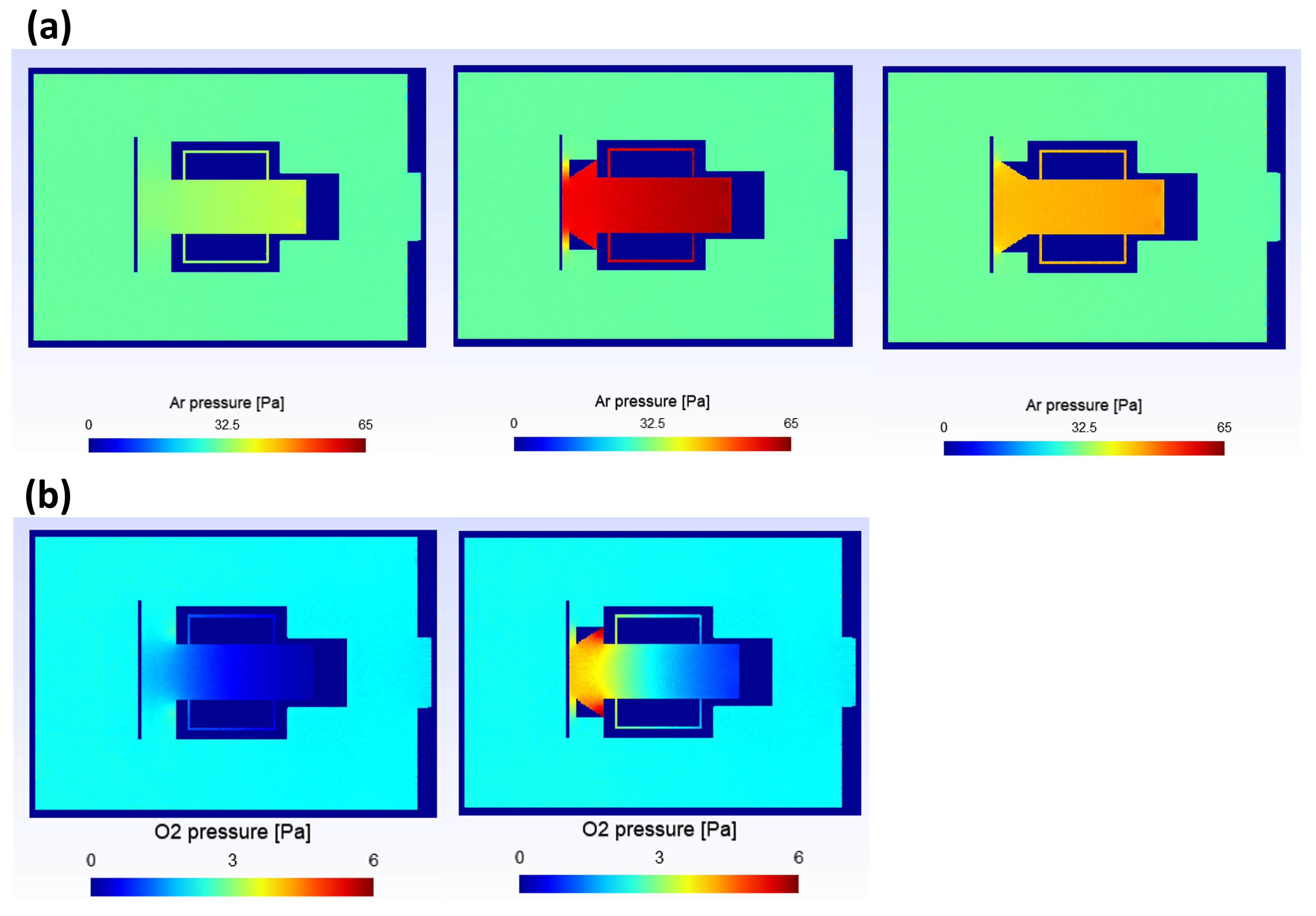
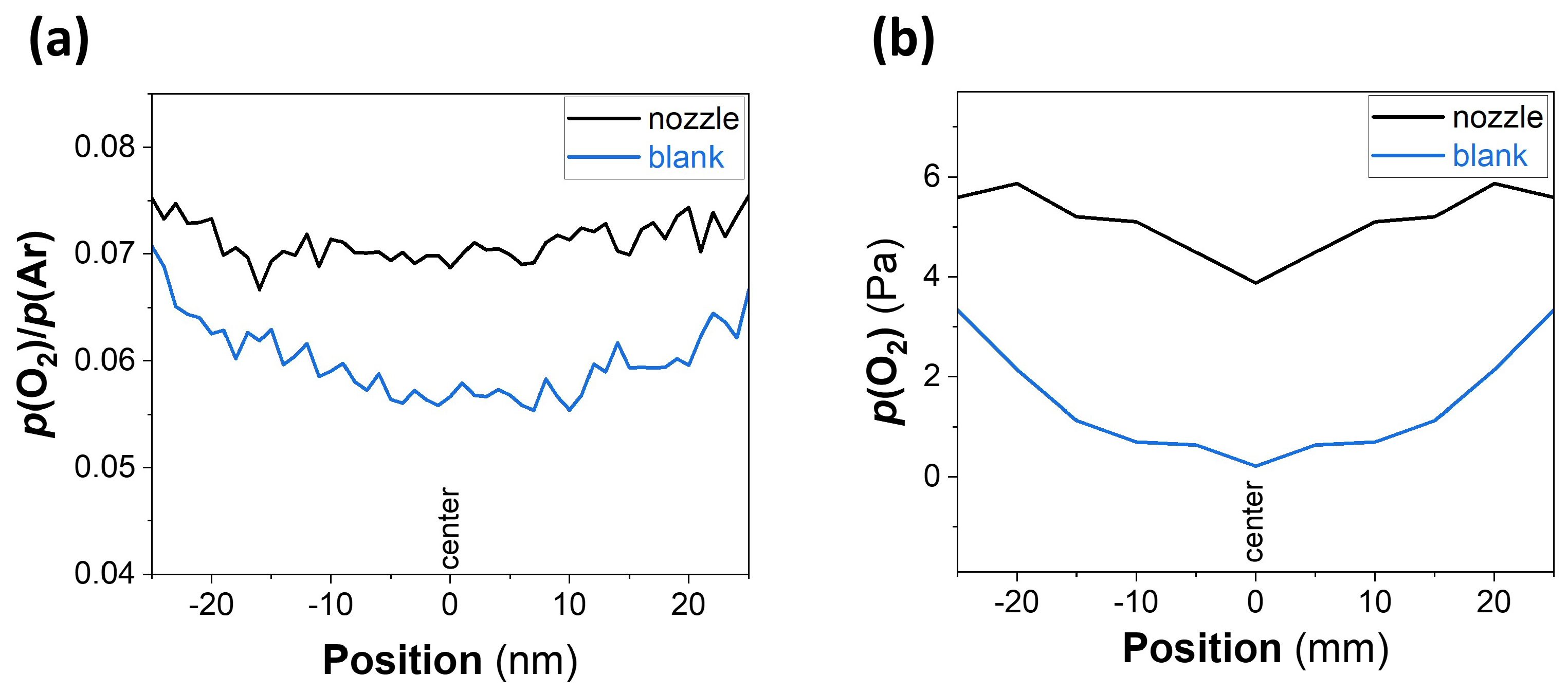
3.1. Simulation
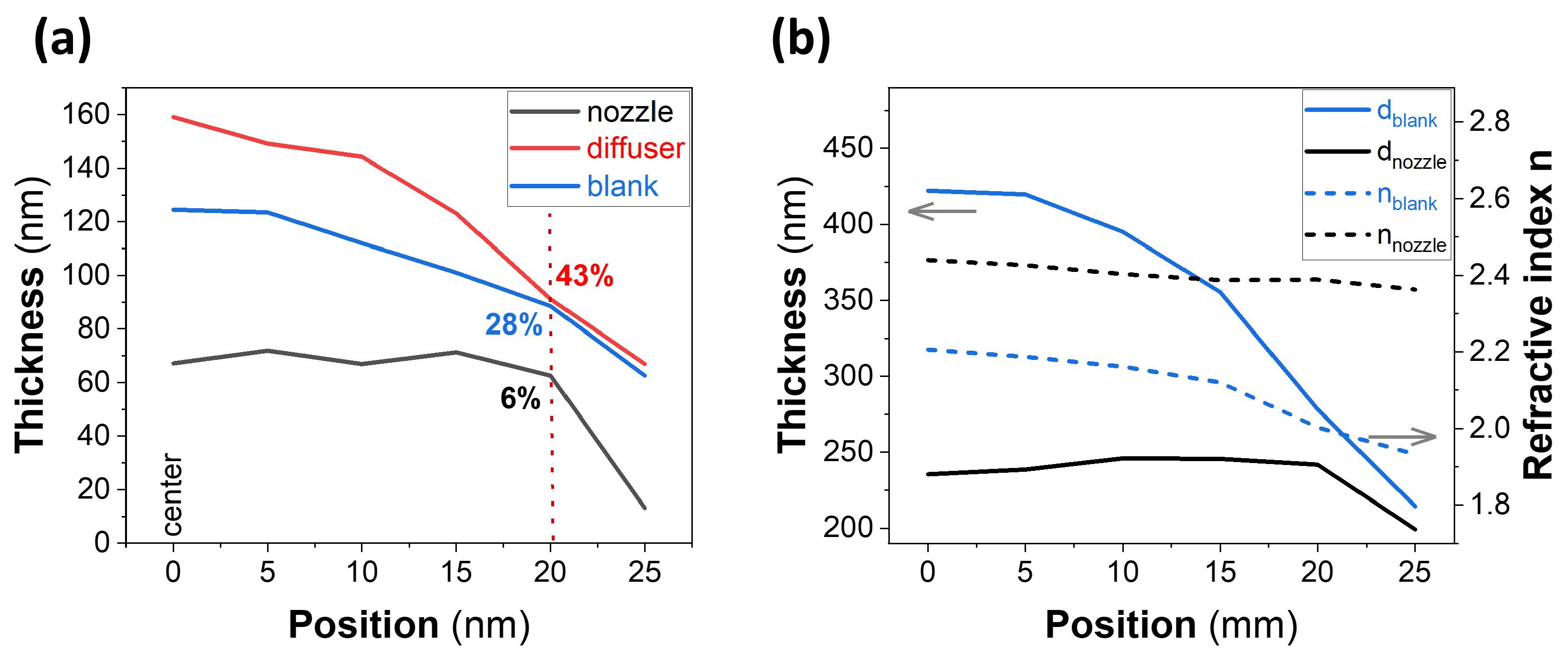
3.2. Deposition
4. Conclusions
Author Contributions
Funding
Institutional Review Board Statement
Informed Consent Statement
Data Availability Statement
Conflicts of Interest
References
- Jirátová, K.; Čada, M.; Naiko, I.; Ostapenko, A.; Balabánová, J.; Koštejn, M.; Maixner, J.; Babii, T.; Topka, P.; Soukup, K.; et al. Plasma Jet Sputtering as an Efficient Method for the Deposition of Nickel and Cobalt Mixed Oxides on Stainless-Steel Meshes: Application to VOC Oxidation. Catalysts 2023, 13, 79. [Google Scholar] [CrossRef]
- Cai, L.; Zhu, F. Toward efficient and stable operation of perovskite solar cells: Impact of sputtered metal oxide interlayers. Nano Sel. 2021, 2, 1417–1436. [Google Scholar] [CrossRef]
- Kumar, A.; Jaiswal, J.; Tsuchiya, K.; Mulik, R.S. Modern Coating Processes and Technologies. In Coating Materials: Computational Aspects, Applications and Challenges; Verma, A., Sethi, S.K., Ogata, S., Eds.; Springer Nature: Singapore, 2023; pp. 33–80. [Google Scholar] [CrossRef]
- Shapovalov, V.I. Modeling of Reactive Sputtering and mdash;History and Development. Materials 2023, 16, 3258. [Google Scholar] [CrossRef]
- LARS-ERIK, G. Hollow Cathode Deposition of Thin Films; Uppsala University: Uppsala, Sweden, 2006; p. 56. [Google Scholar]
- Desch, N.; Lake, M. Formation of pure anatase TiO2 using the reactive pulsed dc magnetron sputtering method for controlling the target poisoning state. Appl. Res. 2023, 3, e202300003. [Google Scholar] [CrossRef]
- Ishii, K.; Kurokawa, K.; Yoshihara, S. High-rate deposition of titanium dioxide films with photocatalytic activities by gas flow sputtering. IEICE Trans. Electron. 2004, 87, 232–237. [Google Scholar]
- Muhl, S.; Pérez, A. The use of hollow cathodes in deposition processes: A critical review. Thin Solid Film. 2015, 579, 174–198. [Google Scholar] [CrossRef]
- Bolotov, M. The Deposition of Thin Metal Films in Low Temperature Plasma of Hollow Cathode Glow Discharge. In Proceedings of the 2020 IEEE 40th International Conference on Electronics and Nanotechnology (ELNANO), Kyiv, Ukraine, 22–24 April 2020; pp. 90–94. [Google Scholar] [CrossRef]
- Kapran, A.; Hippler, R.; Wulff, H.; Olejnicek, J.; Pisarikova, A.; Cada, M.; Hubicka, Z. Characteristics of a pulsed hollow cathode discharge operated in an Ar+O2 gas mixture and deposition of copper nickel oxide thin films. Vacuum 2023, 215, 112272. [Google Scholar] [CrossRef]
- Alktash, N.; Muydinov, R.; Erfurt, D.; Hartig, M.; Gajewski, W.; Szyszka, B. Indigenous facility of the unipolar pulsed power generation for gas flow sputtering of titania films. Rev. Sci. Instrum. 2023, 94, 075104. [Google Scholar] [CrossRef]
- Butcher, K.S.A.; Georgiev, V.; Georgieva, D. Recent Advances in Hollow Cathode Technology for Plasma-Enhanced ALD—Plasma Surface Modifications for Aluminum and Stainless-Steel Cathodes. Coatings 2021, 11, 1506. [Google Scholar] [CrossRef]
- Abe, S.; Takahashi, K.; Mukaigawa, S.; Takaki, K. Comparison of plasma characteristics of high-power pulsed sputtering glow discharge and hollow-cathode discharge. Jpn. J. Appl. Phys. 2020, 60, 015501. [Google Scholar] [CrossRef]
- Sakuma, H.; Ishii, K. Gas flow sputtering: Versatile process for the growth of nanopillars, nanoparticles, and epitaxial thin films. J. Magn. Magn. Mater. 2009, 321, 872–875. [Google Scholar] [CrossRef]
- Paduraru, C.; Belkind, A.; Becker, K.; Lopez, J.; Delahoy, A.; Guo, S.Y. Pulsed DC, Gas-Flow Hollow Cathode Discharge: A source for sputter-Deposition. In Proceedings of the SVC Annual Technical Conference Proceedings, San Francisco, CA, USA, 3–8 May 2003; Volume 46. [Google Scholar]
- Somekh, R. The thermalization of energetic atoms during the sputtering process. J. Vac. Sci. Technol. A Vac. Surf. Film 1984, 2, 1285–1291. [Google Scholar] [CrossRef]
- Ishii, K. High-rate low kinetic energy gas-flow-sputtering system. J. Vac. Sci. Technol. A 1989, 7, 256–258. [Google Scholar] [CrossRef]
- Saitou, Y.; Sakuma, H.; Ishii, K. Estimations of Plasma Parameters and Bias-Sputtering of Cu Films in Gas-Flow-Sputtering Operating at 1-Torr Pressure Region. Trans. Mater. Res. Soc. Jpn. 2005, 30, 311–314. [Google Scholar]
- Morgner, H.; Neumann, M.; Straach, S.; Krug, M. The hollow cathode: A high-performance tool for plasma-activated deposition. Surf. Coat. Technol. 1998, 108–109, 513–519. [Google Scholar] [CrossRef]
- Goebel, D.M.; Becatti, G.; Mikellides, I.G.; Lopez Ortega, A. Plasma hollow cathodes. J. Appl. Phys. 2021, 130, 050902. [Google Scholar] [CrossRef]
- Linss, V.; Bivour, M.; Iwata, H.; Ortner, K. Comparison of low damage sputter deposition techniques to enable the application of very thin a-Si passivation films. In Proceedings of the AIP Conference Proceedings, Bodrum, Turkey, 4–8 September 2019; Volume 2147. [Google Scholar]
- Hoffman, D.; Singh, B.; Thomas, J.H., III. Handbook of Vacuum Science and Technology; Elsevier: Amsterdam, The Netherlands, 1997. [Google Scholar]
- Jung, T.; Westphal, A. High rate deposition of alumina films by reactive gas flow sputtering. Surf. Coat. Technol. 1993, 59, 171–176. [Google Scholar] [CrossRef]
- Delahoy, A.E.; Guo, S.Y.; Paduraru, C.; Belkind, A. Reactive-environment, hollow cathode sputtering: Basic characteristics and application to Al2O3, doped ZnO, and In2O3:Mo. J. Vac. Sci. Technol. A 2004, 22, 1697–1704. [Google Scholar] [CrossRef]
- Olejnicek, J.; Smid, J.; Perekrestov, R.; Ksirova, P.; Rathousky, J.; Kohout, M.; Dvorakova, M.; Kment, S.; Jurek, K.; Cada, M.; et al. Co3O4 thin films prepared by hollow cathode discharge. Surf. Coat. Technol. 2019, 366, 303–310. [Google Scholar] [CrossRef]
- Zouzelka, R.; Olejnicek, J.; Ksirova, P.; Hubicka, Z.; Duchon, J.; Martiniakova, I.; Muzikova, B.; Mergl, M.; Kalbac, M.; Brabec, L.; et al. Hierarchical TiO2 Layers Prepared by Plasma Jets. Nanomaterials 2021, 11, 3254. [Google Scholar] [CrossRef] [PubMed]
- Mihailova, D. Sputtering Hollow Cathode Discharges Designed for Laser Applications: Experiments and Theory. Ph.D. Thesis, Technische Universiteit Eindhoven, Eindhoven, The Netherlands, 2010. [Google Scholar] [CrossRef]
- Tobias, K. Hohlkathoden-Gasflußsputtern zur Verschleißschutzbeschichtung von Kunststoffen; Fraunhofer-Institut für Schicht- und Oberflächentechnik IST: Braunschweig, Germany, 1998; p. 98. [Google Scholar]
- Venkattraman, A.; Alexeenko, A.A. Direct simulation Monte Carlo modeling of metal vapor flows in application to thin film deposition. Vacuum 2012, 86, 1748–1758. [Google Scholar] [CrossRef]
- Thiruppathiraj, S.; Ryu, S.M.; Uh, J.; Raja, L.L. Direct-simulation Monte Carlo modeling of reactor-scale gas-dynamic phenomena in a multiwafer atomic-layer deposition batch reactor. J. Vac. Sci. Technol. A 2021, 39, 052404. [Google Scholar] [CrossRef]
- Serikov, V.; Kawamoto, S.; Nanbu, K. Particle-in-cell plus direct simulation Monte Carlo (PIC-DSMC) approach for self-consistent plasma-gas simulations. IEEE Trans. Plasma Sci. 1999, 27, 1389–1398. [Google Scholar] [CrossRef]
- Kim, J.S.; Hur, M.Y.; Song, I.C.; Lee, H.J.; Lee, H.J. Simulation of Low-Pressure Capacitively Coupled Plasmas Combining a Parallelized Particle-in-Cell Simulation and Direct Simulation of Monte Carlo. IEEE Trans. Plasma Sci. 2014, 42, 3819–3824. [Google Scholar] [CrossRef]
- Zuppardi, G.; Francesco, R. Direct Simulation Monte Carlo Method in Industrial Applications. Methods Appl. Tenutosi A Santa Fe 2009, 6, 1–18. [Google Scholar]
- Jimenez, F.J.; Dew, S.K.; Field, D.J. Comprehensive computer model for magnetron sputtering. II. Charged particle transport. J. Vac. Sci. Technol. A 2014, 32, 061301. [Google Scholar] [CrossRef]
- Sohn, I.; Seo, I.; Lee, S.; Jeong, S. Improved modeling of material deposition during OLED manufacturing using direct simulation monte carlo method on GPU Architecture. Int. J. Precis. Eng. Manuf.-Green Technol. 2019, 6, 861–873. [Google Scholar] [CrossRef]
- Tonneau, R.; Moskovkin, P.; Pflug, A.; Lucas, S. TiOx deposited by magnetron sputtering: A joint modelling and experimental study. J. Phys. D Appl. Phys. 2018, 51, 195202. [Google Scholar] [CrossRef]
- Ivchenko, D.; Zhang, T.; Mariaux, G.; Vardelle, A. On the Validity of Continuum Computational Fluid Dynamics Approach Under Very Low-Pressure Plasma Spray Conditions. J. Therm. Spray Technol. 2017, 6, 3–13. [Google Scholar] [CrossRef]
- Scherg-Kurmes, H. Deposition von Transparenten Leitfähigen Oxiden mit Hoher Ladungsträgermobilität bei Niedriger Prozesstemperatur und Deren Integration in Photovoltaik-Zellen: Numerische Simulation der Physikalischen und Chemischen Vorgänge während der Deposition; Technische Universitaet Berlin: Berlin, Germany, 2017. [Google Scholar]
- Pflug, A. Simulation & Digital Services. Available online: https://www.ist.fraunhofer.de/en/expertise/simulation-digital-services.html (accessed on 30 September 2023).
- Geuzaine, C.; Remacle, J.F. Gmsh: A Three-Dimensional Finite Element Mesh Generator with Built-in Pre- and Post-Processing Facilities. Available online: http://gmsh.info/ (accessed on 30 September 2023).
- Pflug, A.; Siemers, M.; Melzig, T.; Schulz, P. DSMC and PICMC documentation. Available online: https://www.ist.fraunhofer.de/de/kompetenzen/simulation-digital-services/dsmc-picmc.html (accessed on 12 July 2021).
- Koerner, S. Entwicklung Einer Flexiblen Beschichtungstechnologie zur Herstellung von Transparenten Leitfähigen OXIDEN für CuInGaSe2-Solarzellen; Technische Universitaet Berlin: Berlin, Germany, 2023; p. 196. [Google Scholar]
- Liu, T. Computer-Aided Modeling and Simulation of Methods for Optimizing the Output Flow of an Existing Gas Flow Sputtering System. 2018; p. 78; unpublished Master Thesis. [Google Scholar]
- Stadel, O.; Schmidt, J.; Markov, N.; Samoilenkov, S.; Wahl, G.; Jimenez, C.; Weiss, F.; Selbmann, D.; Eickemeyer, J.; Gorbenko, O.Y.; et al. Single source MOCVD system for deposition of superconducting films onto moved tapes. J. Phys. IV 2001, 11, Pr3-1087–Pr3-1094. [Google Scholar] [CrossRef]
- Huang, C.; Tsao, C.; Hsu, C. Study on the photocatalytic activities of TiO2 films prepared by reactive RF sputtering. Ceram. Int. 2011, 37, 2781–2788. [Google Scholar] [CrossRef]
- Mergel, D.; Buschendorf, D.; Eggert, S.; Grammes, R.; Samset, B. Density and refractive index of TiO2 films prepared by reactive evaporation. Thin Solid Film. 2000, 371, 218–224. [Google Scholar] [CrossRef]
- Shakoury, R.; Zarei, A. Optical and Structural Properties of TiO2 Thin Films Deposited by RF Magnetron Sputtering. Silicon 2019, 11, 1247–1252. [Google Scholar] [CrossRef]
- Mohamed, S.; Kappertz, O.; Leervad Pedersen, T.; Drese, R.; Wuttig, M. Properties of TiOx coatings prepared by dc magnetron sputtering. Phys. Status Solidi 2003, 198, 224–237. [Google Scholar] [CrossRef]
- Jiang, J.; Li, B.; Zhang, Z.; Hu, P.; Zhang, F.; Cheng, H.; Yang, F. Influence of the Oxygen Partial Pressure on the Composition and Optical Properties of Electron-beam Evaporated TiOx Films. Phys. Status Solidi 2002, 193, 69–77. [Google Scholar] [CrossRef]
- Wiatrowski, A.; Wojcieszak, D.; Mazur, M.; Kaczmarek, D.; Domaradzki, J.; Kalisz, M.; Kijaszek, W.; Pokora, P.; Mańkowska, E.; Lubanska, A.; et al. Photocatalytic Coatings Based on TiOx for Application on Flexible Glass for Photovoltaic Panels. J. Mater. Eng. Perform. 2022, 31, 6998–7008. [Google Scholar] [CrossRef]


Disclaimer/Publisher’s Note: The statements, opinions and data contained in all publications are solely those of the individual author(s) and contributor(s) and not of MDPI and/or the editor(s). MDPI and/or the editor(s) disclaim responsibility for any injury to people or property resulting from any ideas, methods, instructions or products referred to in the content. |
© 2024 by the authors. Licensee MDPI, Basel, Switzerland. This article is an open access article distributed under the terms and conditions of the Creative Commons Attribution (CC BY) license (https://creativecommons.org/licenses/by/4.0/).
Share and Cite
Alktash, N.; Körner, S.; Liu, T.; Pflug, A.; Szyszka, B.; Muydinov, R. A Coaxial Nozzle Attachment Improving the Homogeneity of the Gas Flow Sputtering. Coatings 2024, 14, 279. https://doi.org/10.3390/coatings14030279
Alktash N, Körner S, Liu T, Pflug A, Szyszka B, Muydinov R. A Coaxial Nozzle Attachment Improving the Homogeneity of the Gas Flow Sputtering. Coatings. 2024; 14(3):279. https://doi.org/10.3390/coatings14030279
Chicago/Turabian StyleAlktash, Nivin, Stefan Körner, Tianhao Liu, Andreas Pflug, Bernd Szyszka, and Ruslan Muydinov. 2024. "A Coaxial Nozzle Attachment Improving the Homogeneity of the Gas Flow Sputtering" Coatings 14, no. 3: 279. https://doi.org/10.3390/coatings14030279
APA StyleAlktash, N., Körner, S., Liu, T., Pflug, A., Szyszka, B., & Muydinov, R. (2024). A Coaxial Nozzle Attachment Improving the Homogeneity of the Gas Flow Sputtering. Coatings, 14(3), 279. https://doi.org/10.3390/coatings14030279