Article

A Comparative Study of the Corrosion Behavior of P110 Casing Steel in Simulated Concrete Liquid Containing Chloride and Annulus Fluid from an Oil Well

1
Petroleum Engineering College, Yangtze University, Wuhan 430100, China
2
Key Laboratory of CNPC for Oil and Gas Production, Yangtze University Branch, Wuhan 430100, China
3
Key Laboratory of Drilling and Production Engineering for Oil and Gas, Wuhan 430100, China
*
Author to whom correspondence should be addressed.
Coatings 2024, 14(3), 294; https://doi.org/10.3390/coatings14030294
Submission received: 28 January 2024 / Revised: 26 February 2024 / Accepted: 26 February 2024 / Published: 28 February 2024

Abstract

:
The corrosion behavior of P110 casing steel in simulated concrete liquid and simulated annulus fluid was investigated to reveal the corrosion pattern and protective properties of corrosion products in the two environments. Potentiodynamic polarization curves, electrochemical impedance spectroscopy (EIS), Mott–Schottky tests, and electrochemical noise (EN) tests were used to study the corrosion behavior of P110 casing steel in simulated concrete liquid and simulated annulus fluid saturated with CO2. Scanning electron microscopy (SEM) combined with Energy-Dispersive Spectrometer (EDS) mapping was used to characterize the corrosion morphology and elemental distribution of P110 casing steel. The results show that the corrosion resistance of P110 casing steel deteriorates with the increasing immersion days in the simulated annulus fluid, the impedance decreases gradually, and the corrosion-product film shows a loose and porous structure. In the simulated concrete liquid, under the condition of containing a low concentration of Cl, the protection of the corrosion products gradually increases with the extension of immersion days. With the increasing concentration of Cl and the extension of immersion days, the electrochemical noise resistance and charge transfer resistance of P110 steel decrease gradually, and the protective property of the corrosion-product film decreases, which is capable of forming steady pitting corrosion.

1. Introduction

Corrosion failure of oil-casing steel in the downhole environment is one of the main factors affecting the safe production of oil and gas. Oil-casing tubing is a significant equipment in the process of oil and gas field development. On one hand, it can fix the formation and prevent collapse of the downhole environment. On the other hand, it can effectively isolate the penetration of the fluid in the wellbore and protect the underground environment as well. At present, a large number of oil and gas wells have entered the high water cut development stage, and coupled with the application of CO2-enhanced oil and gas recovery technology, the working environment of oil-casing steel is more complicated. The outer wall of the casing steel provides an important service in concrete environments, which always contain high concentrations of Cl and high salinity, and is susceptible to local corrosion of the oil casing. The inner wall of the casing is mostly affected in annulus environments, where inorganic salts are mostly used as an aggravating agent, which can easily cause corrosion failure of the casing steel, and where the corrosive gas in the tubing can also invade the annular environment, further inducing casing failure [1].
Currently, some achievements have been made regarding the corrosion behavior of metals in simulated concrete-liquid environments, and the scope of this research has mainly been aimed at the corrosion behavior of simulated concrete liquids in high-pH-value environments. Shi et al. [2] investigated the corrosion behavior of low-alloy steel in a high-pH simulated concrete-pore solution using electrochemical tests, and their research found that the passivation film in low-alloy steel can significantly improve the pitting resistance of the metal, but the pitting resistance of low-alloy steel in an environment with a low concentration of Cl is lower than that of low-carbon steel. However, in a high-Cl-concentration environment, the passivation film of low-alloy steel can dramatically reduce the pitting tendency of the metal. When the passivation film on the metal surface is locally destroyed and the cathode reaction is promoted, meanwhile, the anodic dissolution rate reaction on the metal surface is also accelerated. According to the study of Thangavel et al. [3], the initial concentration of Cl as well as O2 diffusion needs to be considered when evaluating the corrosion behavior of concrete environments, and the ratio of Cl to OH individually cannot fully reflect the overall corrosion situation. The contamination of Cl in concrete environments is a common working condition in cementing processes in oil and gas fields, but due to the “size effect” of the real tube, it is difficult to evaluate the risk of corrosion failure using the concentration of Cl in a concrete environment [4], and the current research still needs to simulate real conditions in a laboratory to evaluate these corrosion conditions [5,6]. Huang et al. [7] investigated the corrosion behavior of P110 casing steel under alkaline-containing and oxidizing media conditions in oil- and gas-well environments, and their study showed that adjusting the ratio of initial oxide to NaOH could control the corrosion rate.
In the downhole environment of oil and gas fields, pitting corrosion and perforation of casing steel in the annulus fluid is another important factor causing casing failure [8]. The annulus fluid is relatively static, and corrosive gases such as CO2 leaking from the pipe gap can easily gather in the annulus, accelerating the serious pitting corrosion of the inner wall of the casing. The existing studies were mainly conducted on the alloy composition of the casing steel, the temperature and pressure of the working environment, and corrosion failure forms [9,10,11]. Zeng et al. [12] found that in a CO2 annulus environment, severe uniform corrosion would be induced in the saturated brine phase, and more serious pitting corrosion would occur in the simulated production solution. The study of Wei et al. [13,14] also pointed out that P110 steel exhibits mainly uniform corrosion failure in the liquid phase and mainly local corrosion in the CO2 environment. Xu et al. [15] concluded that when the Cr content is less than 13%, the corrosion resistance of an alloy will increase with the increase in Cr content. In summary, certain progress has been made in material selection and corrosion failure forms of oil-casing steel. However, there are few reports on the mechanism of local corrosion and pitting corrosion formation, and there are few comparative analyses of the corrosion behavior of oil-casing steel in internal and external working environments.
In this study, the corrosion kinetics mechanisms of P110 casing steel in simulated annulus fluid saturated with CO2 and a simulated concrete-liquid environment are analyzed, and the two kinds of corrosion environments are compared. Immersion experiments were used to study the electrochemical corrosion behavior and morphology of P110 casing steel after immersion for different lengths of time (in days), and EN and EIS techniques were used to investigate corrosion kinetics changes and local corrosion occurrence in the P110 casing steel after different durations of immersion. On this basis, the corrosion failure mechanism of P110 casing steel was combined with the results of Mott–Schottky tests and potentiodynamic polarization curves. Finally, by comparing the corrosion behavior of the P110 casing steel under the two environments, the high-risk working condition was obtained, which provides a theoretical basis for the protection of casing steel from corrosion.

2. Experiments and Materials

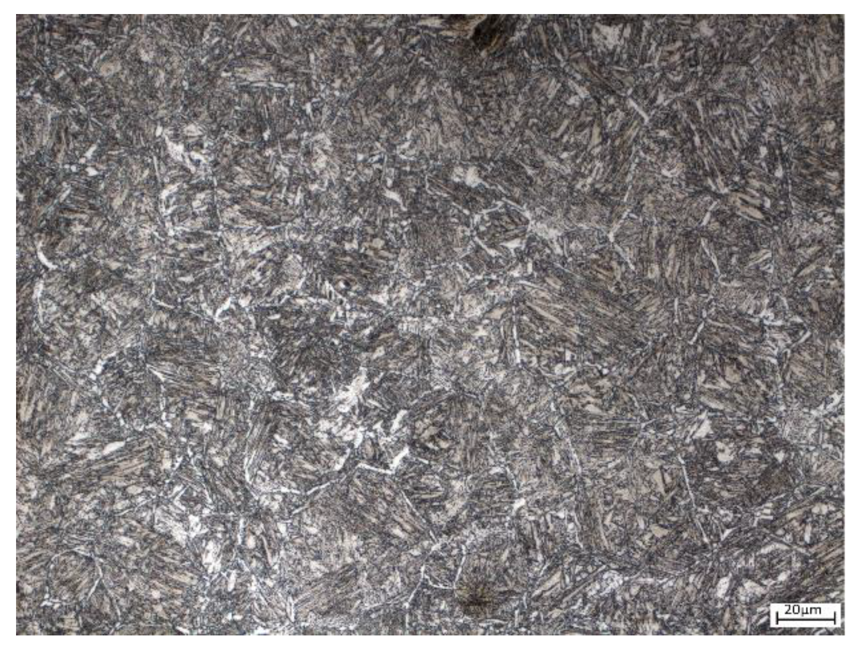
2.1. Experiment Material

The material used in this study is P110 casing steel, which was taken from a certified oil-well casing tube. An Optical Emission Spectrometer (OES) (GNR S3 Minilab, Milan, Italy) was used to test the material’s element composition, and this element composition is shown in Table 1. The metallographic structure of P110 casing steel in its as-supplied state after polishing and etching with 4% nitrate alcohol is shown in Figure 1. The metallographic structure is mainly bainite and martensite, with a small amount of ferrite.

2.2. Electrochemical Tests

The electrochemical working electrodes were P110 casing steel, the cutting size was 10 mm × 10 mm × 3 mm, and the electrode working area was 1 cm2. Each specimen was welded with copper wires on the non-working surface, and then encapsulated with epoxy resin as a working electrode. Before the experiment, the working electrodes were polished step by step with metallographic silicon paper from 80# to 2000#, wiped with anhydrous-ethanol, rinsed with deionized water, dried with cold air, and then stored. The electrochemical tests were displayed on a CS310M electrochemical workstation (CORRTEST, Wuhan, China). The tests adopted a three-electrode system with a platinum sheet as the counter electrode (CE) and a saturated calomel electrode (SCE) as the reference electrode. Open-circuit potential tests were performed at first, and electrochemical impedance spectroscopy (EIS) and potentiodynamic polarization curves were performed after the open-circuit potential was stabilized. The electrochemical impedance spectroscopy measurements were taken according to the AC sine-wave voltage from peak to peak at 10 mV at the open-circuit potential in the frequency range of 10−2 Hz to 105 Hz, and then an equivalent circuit was fitted to the electrochemical impedance spectroscopy. The potentiodynamic polarization curves were scanned from the cathode to the anode with a starting potential of −0.3 V (vs. OCP); the scanning was stopped at a current density of 10−2 A/m2 and the scanning rate was 1 mV/s. The Mott–Schottky curves were tested at a frequency of 1 kHz, with a sine-wave amplitude of 5 mV. The Mott–Schottky curves’ measured potentials spanned from high to low potential, ranging from −0.8 V to 0.5 V, with a potential interval of 50 mV. The electrochemical noise (EN) tests were measured using two identical P100 steel working electrodes and an SCE, with a sampling frequency of 5 Hz and a test time of 3600 s. To minimize the interference of external interferences, the EN measurement system was placed in a Faraday shielded box (Shanghai Xianren Instrument Co., Ltd., Shanghai, China). After the electrochemical noise tests, the DC component of the original electrochemical noise was removed through polynomial fitting. All potentials herein are relative to the SCE in this paper.
Saturated Ca(OH)2 supernatant was used as the base solution system to simulate the concrete environment [16,17], and the pH value of the base solution was 13. NaCl was added into the simulated concrete liquid, and the concentration of Cl was kept at 0.001, 0.05, 0.1, 0.3, 0.5 mol/L; then, deoxygenation with N2 was performed for 3 h, and it was stored after sealing. The simulated annulus fluid was taken from a CO2-driven oil-well environment with the following compositions: NaHCO3 2.7 g/L, NaCl 8.2 g/L, Na2SO4 0.33 g/L, CaCl2 1.1 g/L. The pH value was adjusted to 4 with 10% glacial acetic acid and 10% NaOH solution, and the N2 was deoxidized for 3 h, and then saturated with CO2 for 4 h [18]. The experimental container gaps or crevices were sealed with silicone rubber. The experimental simulation solutions were configured using analytically pure-grade (AR) reagents and deionized water. The experiment systems were immersed in the simulated solutions for 10 d. EIS and EN tests were carried out at 1 d, 3 d, 5 d, 7 d, and 10 d. Mott–Schottky curves and potentiodynamic polarization curves were measured at 10 d, respectively. The deoxygenation operation was performed in the experimental solutions by bubbling N2 at the end of each experiment, and the simulated annulus fluid was saturated with CO2. A water bath was used to provide a constant temperature environment to maintain the experimental temperature at 60 °C.

2.3. Surface Analysis

The P110 steel was made into 30 mm × 15 mm × 3 mm portions, and the test sample was soaked in a round hole with a diameter of 4 mm at 1 mm away from the edge of the sample. Before the experiment, the immersion specimens were polished step by step with metallographic silicon paper from 80# to 2000#, wiped with anhydrous ethanol, rinsed with deionized water, and the N2 was blown dry for later use. The specimens were suspended with non-metallic wires and then fixed in a sealed container; the immersion experiment time was 10 d, and the experiment temperature was 60 °C. At the end of the experiment, the specimens were ultrasonically cleaned for 3 min, rinsed with deionized water, and purged with N2. The corrosion morphology was observed using a ZEISS MELIN Compact scanning electron microscope (ZEISS, Oberkochen Germany), and the EDS mappings were performed using Oxford X-MAXN (Oxford Instruments, Oxford, UK) for elemental analysis.

3. Results

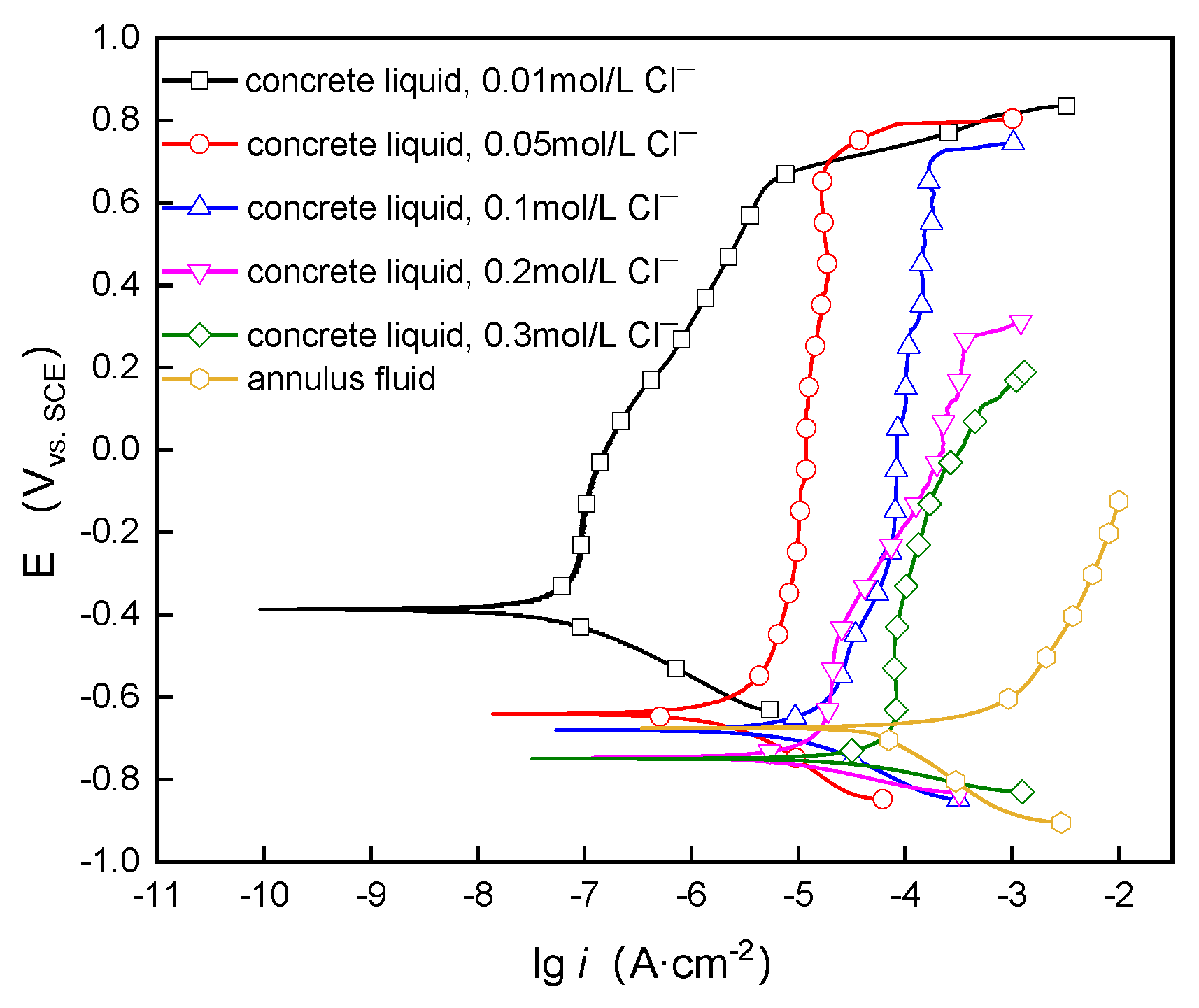
3.1. Potentiodynamic Polarization Measurements

The potentiodynamic polarization curves of P110 in simulated concrete liquid with different concentrations of Cl and simulated annulus fluid at 60 °C are shown in Figure 2. The potentiodynamic polarization curves containing passivation intervals were fitted to the passivation current density (ip) and passivation potential (Ep), and the polarization curves in the activated state were fitted to the corrosion current density (icorr) and corrosion potential (Ecorr) using Tafel extrapolation; these fitting results are shown in Table 2. As can be seen from Figure 2, a protective passivation film structure was generated on the surface of the P110 casing steel after immersion for 10 d at five concentrations of Cl in the simulated concrete-liquid environment. In the simulated concrete-liquid environment, with the increase in Cl concentration, the polarization curve gradually shifted to the right, which indicates that the electrochemical reaction activity increased and promoted the corrosion of the P110 steel, and the passivation interval gradually became shorter, which indicates that the passivation film was less protective. Also, in the anodic region of the polarization curve, the anodic slope was changed, in which the anodic polarization curves went through the activation–passivation transition zone, and shifted to the stable passivation zone; finally, the passivation film was broken down because of the high anodic potential. Moreover, ip was positively correlated with the Cl concentration: with the increasing Cl concentration, ip increased, which indicates that the presence of Cl was detrimental to the structure of the passivation film of the P110 casing steel in the simulated concrete-liquid environment, and also indicates that the presence of Cl increases the corrosion tendency of N80 steel. In the simulated annulus-fluid environment, the P110 casing steel was activated, and the icorr was significantly greater than that of the simulated concrete-liquid environment, in which no protective corrosion-product film was generated; also, the corrosion rate was significantly higher than that of the simulated concrete-liquid environment.

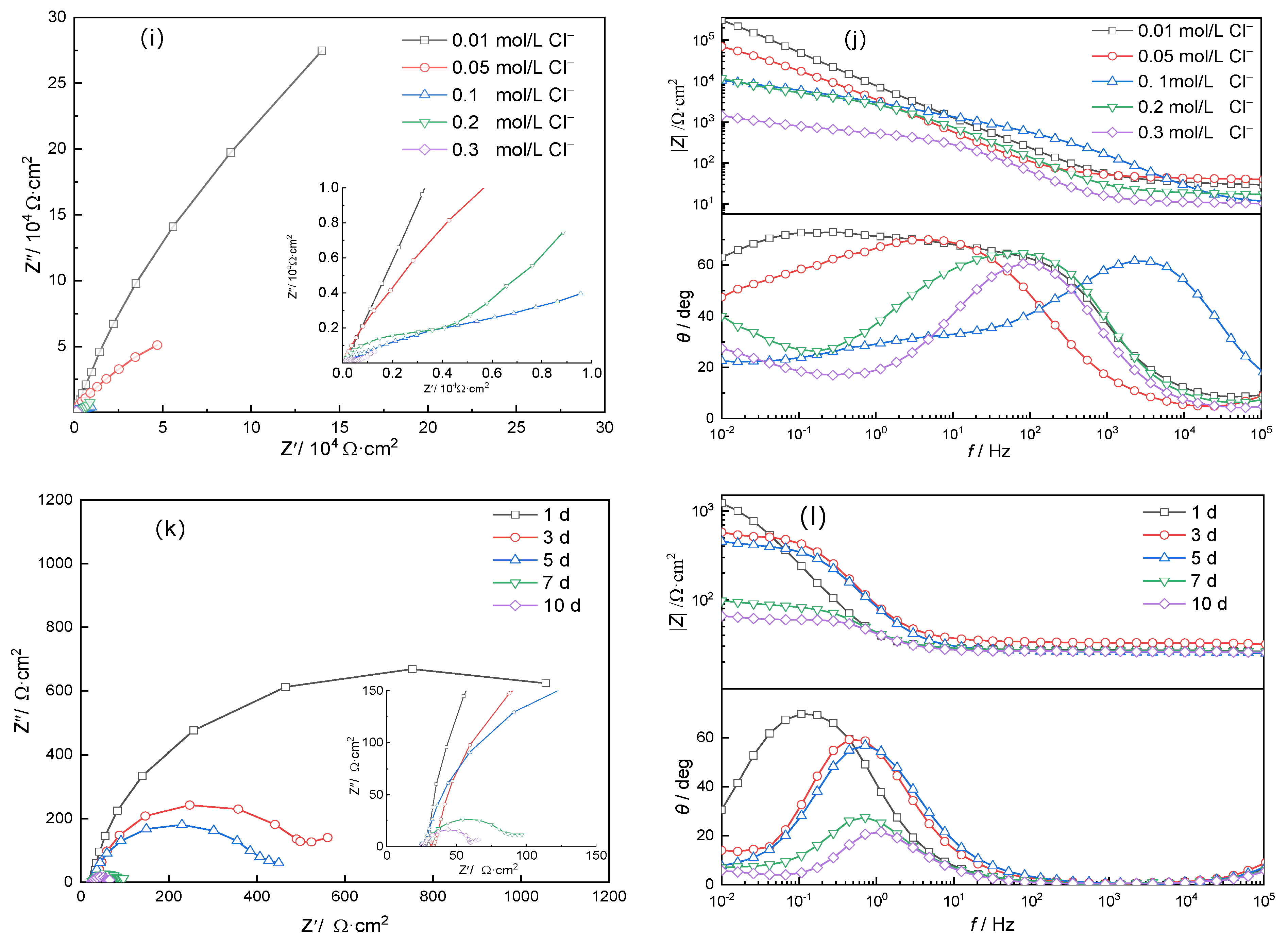
3.2. Electrochemical Impedance Spectroscopy

Figure 3 shows the electrochemical impedance spectroscopy (EIS) results for P110 casing steel in simulated concrete-liquid solution and simulated annulus fluid at a test temperature of 60 °C. The EIS measurements were fitted using the equivalent circuits R(Q(R(QR))) and R(QR), as shown in Figure 4, and the fitting results are shown in Table 3, where Rs represents the solution resistance, Qf is the passivated film capacitance constant phase angle element, Qdl is the double-layer capacitance constant phase angle element, n is the dispersion coefficient, Rf is the passivated film resistance, and Rct represents the charge transfer resistance [19,20].
Figure 3a,c,e,g,i,k show the Nyquist diagrams of P110 for different days of immersion, and Figure 3b,d,f,h,j,l show the Bode diagrams of P110 for different days of immersion. From the Nyquist diagrams, it can be seen that the EIS diagrams of P110 are all characterized by a single capacitive semicircular, indicating that the corrosion process was mainly controlled by electrochemical reactions. Under the same number of immersion days, but with increases in the concentration of Cl in the simulated concrete-liquid environment, the capacitive semicircular radius in the Nyquist plot gradually decreases, and the impedance modulus in the Bode plot also decreases, which indicates that the corrosion resistance of the P110 casing steel decreased with the increase in the concentration of Cl. Also, the impedance modulus in the simulated annulus fluid is smaller than that in the simulated concrete-liquid environment after the same number of days of immersion, which indicates that the corrosion degree was higher (i.e., the P110 corroded to a greater extent), which is consistent with the results of the polarization curves.
By analyzing the EIS diagrams of P110 casing steel in the two environments, it can be seen that in the simulated concrete-liquid environment, when the immersion time of the P110 steel was in the range of 3 d to 10 d, the frequency–phase angle diagrams of the Bode plots in the middle and low frequency regions have constant phase angle intervals, and the phase angle values are larger than other conditions, which indicates that in these environments, a passivation film was generated by the P110 steel; at this time, there were defects in the passivation film on the surface of the metal, and corrosive ions could be transported to the metal substrate through these defects. Therefore, the components Qf and Rf correlated to the corrosion film layer were considered in the equivalent circuit to characterize the changes in the film layer of the corrosion products, and the equivalent-circuit diagram of Figure 4a was used for the EIS fitting in such conditions [18,19]. After 1 d of immersion, the Nyquist diagram is dominated by a single capacitive semicircle, indicating that the electrochemical reaction was mainly controlled by charge transfer. In the annulus-fluid environment, the highest value of the phase angle in the Bode plot of P110 gradually shifts to the high-frequency region as the number of days of immersion increases, indicating that the electrochemical reaction activity increased, the charge transfer rate accelerated, and the corrosion became more severe with the increase in the number of days of immersion; so, the equivalent circuit diagram of Figure 4b was used for the fitting in the two environments mentioned above.
From the EIS results, it can be seen that in the simulated concrete-liquid environment, when the concentration of Cl was 0.01 mol/L, the value of Rct increased gradually with the increase in immersion time, which indicates that the corrosion products of the P110 casing steel had protective properties under a low concentration of Cl, the protective properties increased gradually, the corrosion tendency decreased, and the generation of the protective corrosion products was greater than the dissolution rate of the products. The protective properties of the corrosion products increased with the extension of the immersion time. When the concentration of Cl was 0.05 to 0.2 mol/L, the value of Rct increased and then decreased with the prolongation of the immersion time; the Rct reached the peak value at 7 d of immersion with the 0.05 mol/L concentration of Cl, and the Rct reached the peak value at 3 d of immersion in 0.1 mol/L and 0.2 mol/L Cl, which meant that the corrosion rate decreased and then increased during the immersion process. This indicates that the corrosion rate decreased and then increased during the immersion process, the charge transfer rate increased, and the degree of corrosion increased, which was related to the weakening of the protective property of the corrosion products. When the concentration of Cl reached 0.3 mol/L, the value of Rct decreased with the increase in immersion time, indicating that the corrosion products generated in this case were not protective. In the annulus fluid, the Nyquist diagram of P110 showed an eccentric arc, and the immersion time was prolonged; the radius of the capacitive arc was gradually reduced, the impedance modulus value decreased, and the decline was most drastic after 7 d of immersion, which indicates that the corrosion resistance of P110 casing steel gradually decreased with the prolongation of immersion time, and there was a tendency towards localized corrosion.

3.3. Mott–Schottky Measurements

The results of the Mott–Schottky curves of P110 casing steel in the simulated concrete-liquid environment are shown in Figure 5. These tests mainly illustrated the semiconductor nature of the passivation film generated by the P110 casing steel in conditions of different concentrations of Cl, and discussed the effect of structural changes in the passivation film on the corrosion behavior in Cl containing environments. According to the Mott–Schottky theory, there existed a relationship between the space charge layer capacitance Csc and the electrode potential E, as shown in Equation (1):
1 C S C 2 = 2 ε ε 0 e N q ( E E f b k T e )
where Nq is the carrier concentration, ε is the semiconductor permittivity, ε0 is the vacuum permittivity, Efb is the flat-band point potential, k is the Boltzmann constant, q is the elementary charge, and T is the absolute temperature [21]. It can be seen that in plotting between E and Csc−2, the two should be linear when the Mott–Schottky relation is satisfied. When the slope of this linear relationship is positive, the potential interval presents n-type semiconductor properties, and when the slope of the straight line is negative, it presents p-type semiconductor properties, and the slope of the straight line on the potential axis can be used to find out Efb [22,23].
As can be seen in Figure 5, P110 casing steel showed a linear relationship in the range of −0.8 V to 0.2 V with a positive slope under the five concentrations of Cl, showing an n-type semiconductor nature, and the slope was related to the donor density (ND), which indicates that the carriers were mainly supplied by electrons [24]. The relative permittivity of the iron oxide was chosen to be taken as 12, and the donor density (ND) and Efb on the surface of the P110 casing steel were fitted according to the test results of the Mott–Schottky curves in combination with Equation (1); the results of this fitting are shown in Table 4.
From Table 4, when the concentration of Cl was 0.01 mol/L, the ND value was the smallest, indicating that at this time, the passivation film of the P110 steel was the most dense. The charge transfer was slow when the concentration of Cl was increased to more than 0.1 mol/L, the sizing density increased by one order of magnitude, and with the increase in the concentration of Cl, the ND continued to increase, indicating that at this time, the defects in the passivation film on the surface of the P110 steel increased, with the charge transfer accelerating and the passivation film conductivity increasing. This led to the protective properties being decreased.

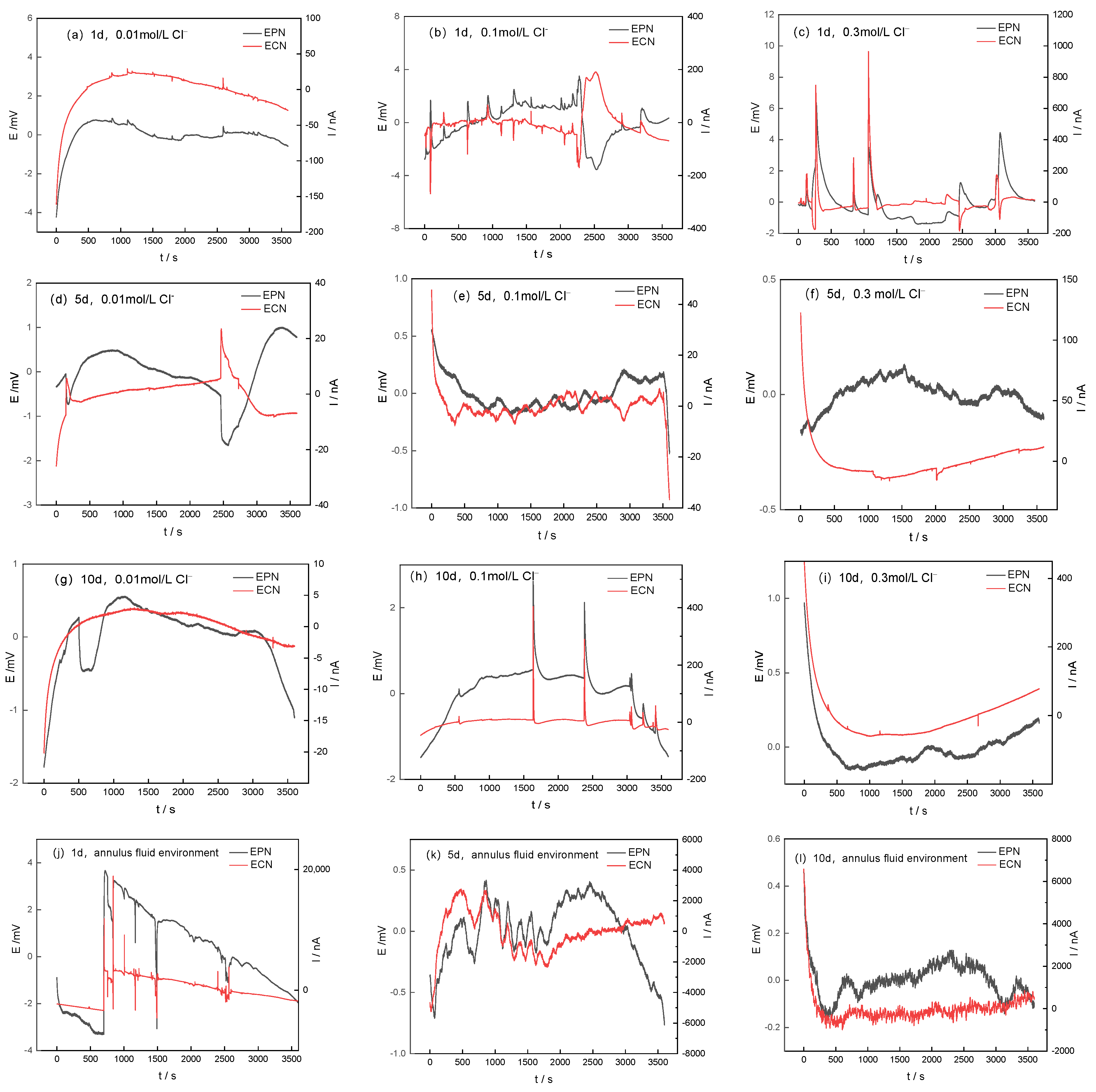
3.4. Electrochemical Noise Measurements

3.4.1. Time-Domain Analysis

Figure 6 shows the time-domain spectra of EN of P110 casing steel in the simulated concrete-liquid environment with different immersion days for removing the DC drift. The corrosion state of P110 casing steel under different immersion times can be evaluated based on the variation in the time-domain spectra [25,26]. When the concentration of Cl was 0.01 mol/L, a small number of transient peaks appeared in the P110 casing steel at an immersion time of 1 d (Figure 6a), the potential noise was synchronized with the trend of the current noise, the transient peaks of the current and potential showed a rapid rise followed by a rapid fall, and a passivation film was gradually formed at this stage. When immersed for 5 d (Figure 6d), a larger transient peak appeared, the current and potential fluctuated in the opposite direction, the potential decreased and the current then increased, and the changes in the time domain were synchronized, but in the opposite direction. The overall trend of the electrochemical potential noise (EPN) was upward, and the EPN peak rapidly decreased and then slowly increased, which indicates that the passivation film of P110 casing steel in the simulated concrete-liquid environment containing Cl was in the process of pitting nucleation and repair. The electrochemical current noise (ECN) then rose rapidly and then decreased slowly—the reason for such a phenomenon being related to the expansion of metastable pitting in the passivation membrane breakage—and the noise current decreased after the passivation film was broken. The passivation membrane repair rate was greater than the dissolution rate of aggressive ions. During the immersion time of 10 d (Figure 6g), the potential decreased and then rose slowly, but at this time, there was no noise current flow, and there were fewer transient peaks in the time domain, indicating that at this time a steady-state passivation film had been generated, and the erosive dissolution of Cl did not constitute an effect on the structure of the passivation film. In the P110 casing steel immersed in a simulated concrete-liquid environment with a concentration of Cl at 0.1 mol/L, from 1 d to 5 d of immersion (Figure 6b,e), the current potential presented alternating synchronous anisotropic transient peaks, and this process was related to the repair of the surface generated passivation film and the generation of sub-stable pitting corrosion. The repair of the passivation film and the dissolving action of Cl exhibited a dynamic interaction process, and Cl competitive adsorption occurred on the active sites of the steel matrix. The passivation film was also repaired at this stage, indicating that the P110 casing steel had a tendency towards localized corrosion at this time. When the immersion time was 10 d (Figure 6h), the transient peak fluctuations and the quantities of current and potential increased significantly, which indicates that steady-state pitting corrosion had been generated at this time. Also, the potential and current presented a synchronous trend in the same direction, indicating that this time was mainly affected by Faraday current. The transient peak was mainly the current peak formed by pitting corrosion, the electrode surface was mainly for the solubilization of Cl, and the protective properties of the passivation film disappeared. When the P110 casing steel was in a simulated concrete-liquid environment with a concentration of Cl at 0.3 mol/L, simultaneous isotropic fluctuation transient peaks of EPN and ECN appeared at the early stages of immersion (Figure 6c), which indicates that the metastable pitting stage had been entered at this time, with an enrichment of Cl on the surface, an increase in the local electrical conductivity of the passivation film, local dissolution of the passivation film, and a reduction in the protective properties. When the immersion time was 5 d to 10 d (Figure 6f,i), the number of potential transient peaks was higher, and the synchronization of the current and potential disappeared; combined with the results of the EN resistance calculation, it can be seen that the electrode surface was in a state of active dissolution, the electrode surface was mainly undergoing an anodic dissolution reaction, and the electrode surface entered into the period of localized corrosion. In the annulus-fluid environment of P110 casing steel, when the immersion time was 1 d, there were synchronous potential and current peaks and isotropic fluctuations, and the electrode surface entered the pitting-corrosion formation period. When the immersion time was 5 d to 10 d, the number of transient peaks of current and potential increased, the electrode surface underwent localized corrosion, and the amplitude of the transient peaks of ECN and EPN were significantly higher than that of the simulated concrete-liquid environment, which indicates that the electron transfer rate was faster in the annulus-fluid environment, and electrochemical reactions were more likely to happen [27].
In time-domain analyses of electrochemical noise, statistical analysis is often used to quantitatively describe the degree of corrosion, and the electrochemical noise resistance Rn is calculated using Formula (2) [28]:
R n = S v / S I
where Sv is the standard deviation of potential, V; SI is the standard deviation of current, A/cm2; Rn is the noise resistance, Ω·cm2. The Rn is negatively correlated with the corrosion rate. The larger the Rn, the smaller the corrosion degree and the better the protection of the passivation film [29]. From the fitting results in Table 5, it can be seen that when the concentration of Cl was 0.01 mol/L, Rn increased with the extension of the immersion time, which indicates that the corrosion resistance of P110 casing steel gradually increased in this environment, and the passivation film protection was strengthened. When the concentration of Cl was 0.1 mol/L, with the extension of immersion time, Rn was basically in the same order of magnitude, and the fluctuation was relatively stable, which was related to the formation and development of pitting corrosion in the P110 casing steel in this period; in such a concentration, passivation film dissolution and repair occurred basically in a stage of dynamic equilibrium. Deposition and dissolution of the corrosion products were mainly carried out on the surface of the P110 casing steel at this stage. When the concentration of Cl was 0.3 mol/L, Rn decreased by one order of magnitude with the prolongation of the immersion time, indicating that the corrosion resistance of P110 was reduced in this environment, and locally stabilized pitting had been generated. In the annulus-fluid environment, the Rn value of P110 gradually decreased with the extension of the immersion time, which implies that localized corrosion had occurred in the simulated annulus fluid, and the Rn value was significantly lower than that in the simulated concrete-liquid environment, which suggests that the corrosion of P110 was more intense in the simulated annulus-fluid environment, which is in agreement with the results of the time-domain analysis and the electrochemical tests.

3.4.2. Frequency-Domain Analysis

The power spectral density (PSD) of the EN was obtained from frequency-domain analysis using the fast Fourier transform (FFT), and the following relationship was found between the PSD and the frequency of the electrochemical noise:
log PSD = A i + S i log f
where PSD is the power spectral density, A2·Hz−1; Ai represents the noise intensity; Si is the diagonal part of the power spectral density curve; and f is the frequency, Hz. The PSD spectra were obtained through FFT processing of the EN under different conditions, and the PSD spectra of the ECN are shown in Figure 7.
When the frequency in the PSD spectra is less than a 10−2 interval, there is a level of white noise (WI); the higher the level of WI in the PSD spectra, the more intense the corrosion behavior becomes. At a concentration of Cl at 0.01 mol/L, the WI level gradually shifted to the negative direction, which indicates that the corrosion rate gradually decreased [30]. When the concentrations of Cl were 0.1 and 0.3 mol/L, the WI values decreased and then increased, and this process was related to the generation of the passivation film and the competitive adsorption of Cl. After 5 d of immersion, the protective property of the passivation film decreased and the corrosion rate increased. In the annulus-fluid environment, the WI level was two orders of magnitude higher than that in the simulated concrete-liquid environment, indicating that the corrosion rate of P110 in the annulus fluid was significantly higher than that in the simulated concrete liquid. The order of magnitude of the WI did not change significantly after different days of immersion and there was no protective corrosion product generated in the simulated annulus-fluid environment.

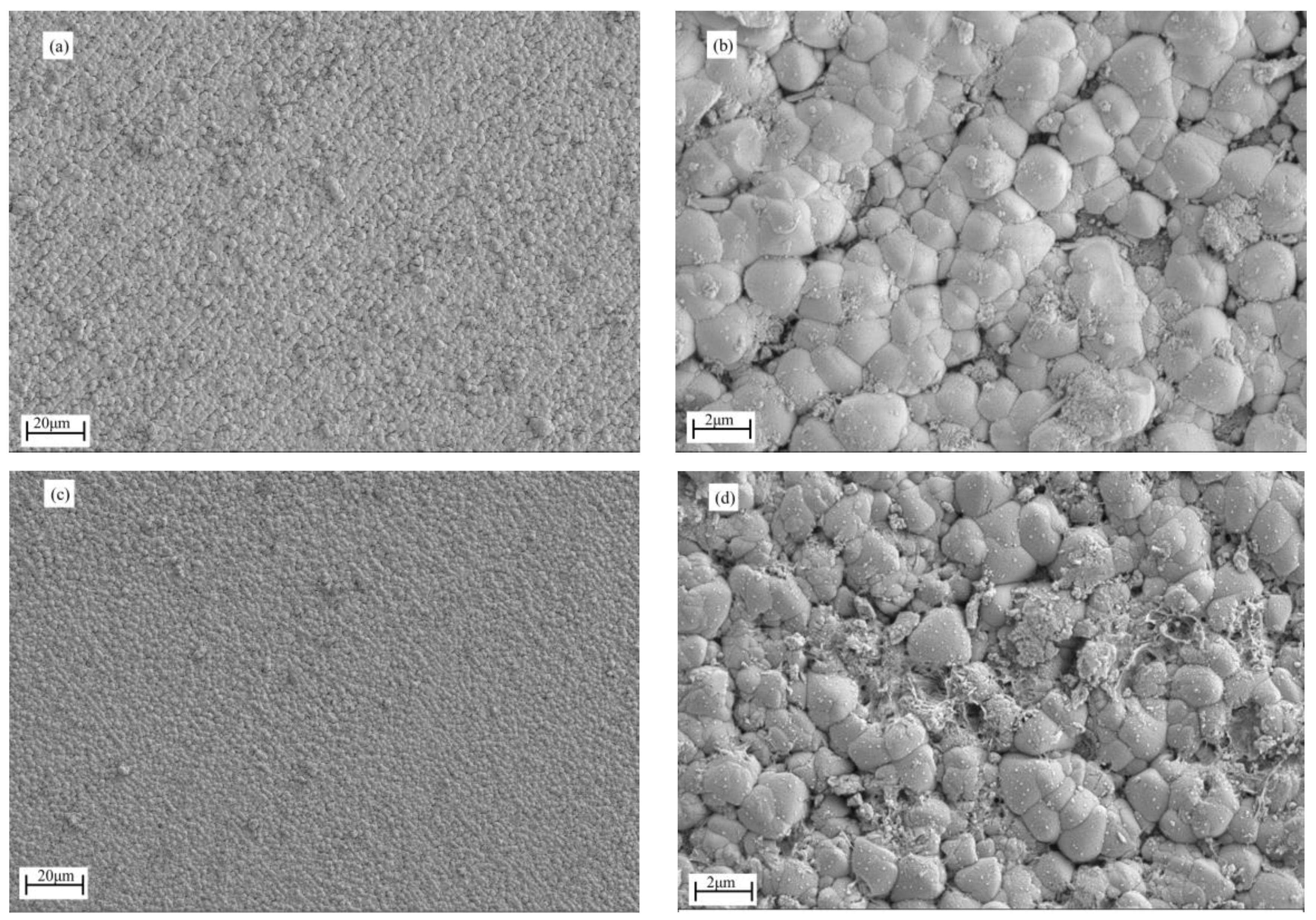
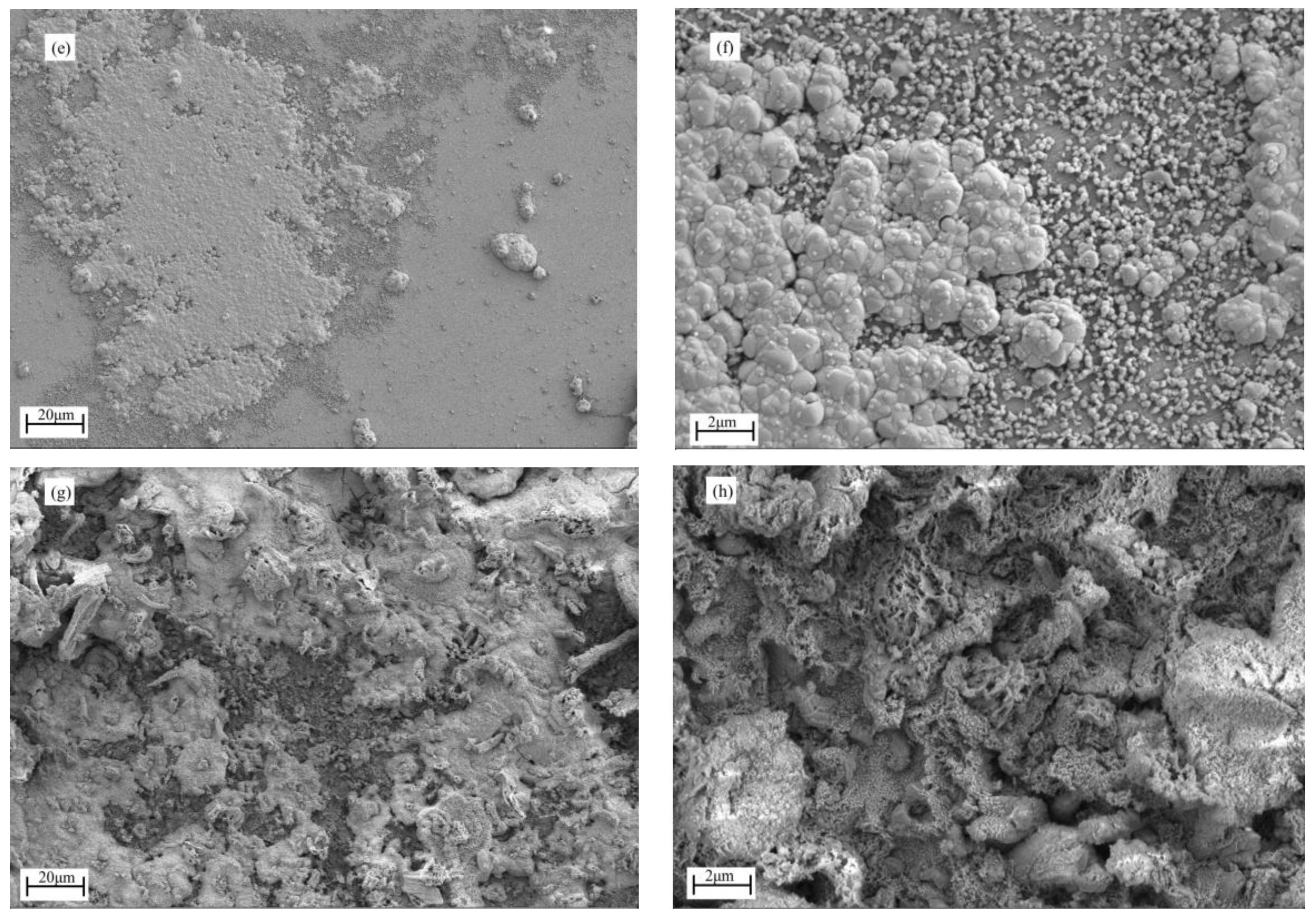
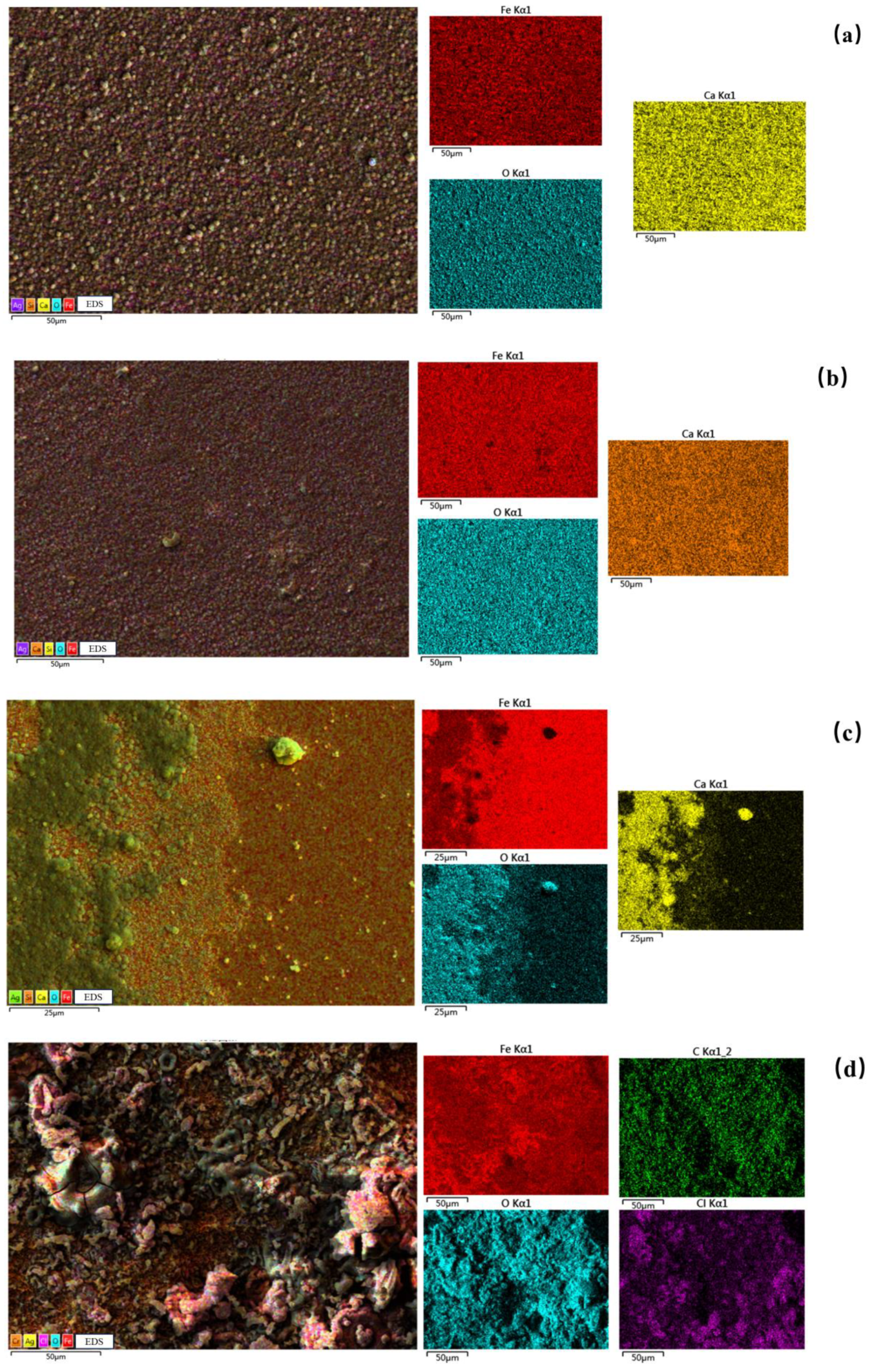
3.5. Corrosion Morphology Analysis of P110-Casing-Steel Specimens

The SEM corrosion morphology of P110 casing steel in different environments is shown in Figure 8. As can be seen from the figures, the surface of P110 casing steel in the simulated concrete-liquid environment generated a corrosion-product film, and the corrosion products on the surface of P110 steel presented a double-layer film structure. When the concentration of Cl was 0.01 and 0.1 mol/L, the surface of the P110 casing steel formed a relatively dense corrosion product: when observed under low magnification (500×), the corrosion product’s structure was regular, and it could cover the metal substrate more completely; under high magnification (5000×), the corrosion product was looser in the outer layer and more dense in the inner layer, and the collective outer layer of the corrosion product was almost complete, which indicates that the corrosion products generated in this state were more protective than those generated in the other simulated concrete-liquid environments. This indicated that the corrosion products generated in this state were better protected, and the passivation film was denser, hindering the further corrosion of aggressive ions. When the concentration of Cl was 0.1 mol/L, breakage of the corrosion products was visible under the high-magnification field of view, and local defects that were not covered by the corrosion products were visible. When the concentration of Cl was 0.3 mol/L, some corrosion products were visible under low magnification, and the distribution of corrosion products was discontinuous, with defects; also, the corrosion products in the inner and outer layers under high magnification showed a loose and porous structure, and the base metal matrix was visible at the uncovered place of the corrosion products. At this time, Cl could be adsorbed to the specific active site to induce steel corrosion of the P110 casing steel, so the corrosion products generated under this condition had poor protective properties. As the corrosion products generated in this condition were less protective and could not hinder the contact between the aggressive medium and the metal substrate, localized pitting corrosion was likely to occur. In the simulated annulus fluid, under low magnification, the corrosion products on the surface of the P110 casing steel were unevenly distributed, no regular corrosion product structure could be seen, and local pitting defects were visible on the metal substrate; under high magnification, the corrosion-product film on the P110 casing steel formed a loose and porous structure, and the corrosion products showed a stepped irregular distribution, which was likely related to the CO2 corrosion.
Figure 9 shows the EDS mapping results of P110 casing steel after 10 d of immersion. From this figure, it can be seen that the corrosion products on the surface of P110 casing steel in the simulated concrete-liquid environment mainly contained Fe, O, and Ca elements, and in the simulated annulus-fluid environment mainly contained Fe, O, C, and a small number of Cl elements. The Ag element in the EDS mapping originated from a silver-spraying treatment that was applied in order to enhance the conductivity of the substrate. When the concentration of Cl was 0.01 and 0.1 mol/L, Fe, O, and Ca elements were uniformly distributed on the surface of the metal substrate; at this time, the corrosion products were more homogeneous, and the main corrosion products were iron oxides and a calcium-based scale layer. When the concentration of Cl was 0.3 mol/L, Ca and O elements were mainly covered in the outer layer of the metal substrate, and Fe and O elements were mainly in the inner layer, which indicates that the corrosion products were mainly a calcium-containing scale layer in the outer layer and iron oxides in the inner layer. In the simulated annulus fluid, the corrosion products mainly contained Fe, C, O, and Cl elements, which was related to the CO2 and high concentration of Cl in the working environment; these corrosion products might have been composed of iron–carbon oxides, iron oxides, and part of the scale material.

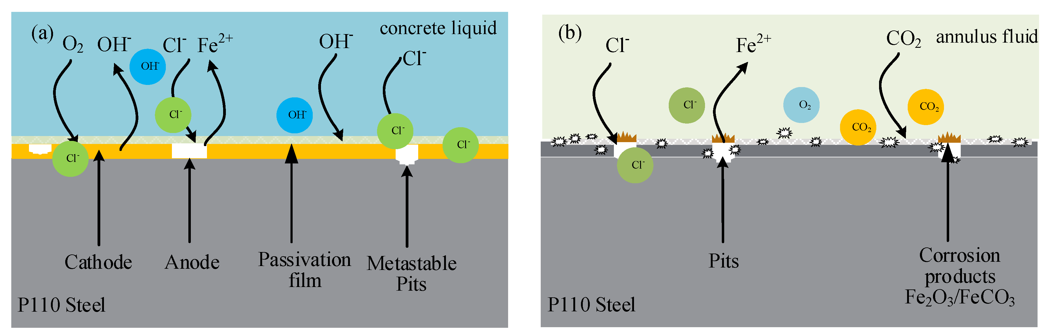
3.6. Corrosion Mechanism Analysis

P110 casing steel had a tendency towards local corrosion in the simulated annulus fluid and in the simulated concrete liquid, where the anodic reaction was mainly the dissolution reaction of iron. For the simulated concrete-liquid environment, the corrosion mechanism is shown in Figure 10a, and the cathodic reaction that occurred in the strongly alkaline environment was mainly oxygen absorption corrosion. In the simulated concrete-liquid environment containing Cl, the self-repair of the passivation film and the dissolution process of Cl alternated with each other, and the passivation film was in a dynamic process of destruction and self-repair, forming the passivation film of P110 casing steel mainly by following the process described below:
3Fe + 8OH−8e→Fe3O4 + 4H2O
2Fe + 6OH−6e→Fe2O3 + 3H2O
When the concentration of Cl was 0.01 mol/L, a dense passivation film was formed on the surface of the P110 steel at a high concentration of OH. During the immersion process, Rct and Rn gradually increased, while WI levels gradually decreased, and the electrochemical reaction was inhibited. At this time, the passivation film formed was the most compact and had the best protection, and the protection of the passivation film gradually increased with the extension of immersion time. When the concentration of Cl was 0.05~0.2 mol/L, competitive adsorption of the Cl and OH occurred; then, at this concentration, the Rct increased and then decreased with the prolongation of the immersion time. The effective protection time of the passivation film was shortened with the increase in the concentration of Cl. In this period, Cl and OH were competitively adsorbed on the active sites on the surface of the steel substrate, and the initial passivation film repair process was greater than the effect of the local dissolution process of Cl; at this time, the EN test results showed metastable pitting corrosion. When the concentration of Cl increased to 0.3 mol/L, Rct and Rn decreased with the extension of immersion time, and the transient peak of EPN increased. The corrosion current density reached its maximum at 10 d of immersion. At this time, the passive film on the surface of the P110 steel exhibited local complete rupture, exposing the metal matrix, and local corrosion occurred.
The minimum transient of the electrochemical potential corresponds to the initiation of the passivation film repair from the metastable pitting. Comparing the EN results of P110 casing steel in the simulated concrete-liquid environments at 10 d of immersion, it can be seen that there was no current flowing on the surface of P110 steel after the potential decreased under the condition of the 0.01 mol/L concentration of Cl, whereas in the environments containing Cl at 0.1 and 0.3 mol/L, fluctuations in the electrochemical potential noise could cause fluctuations in the passivation film of the P110 steel. This is because the P110 casing steel’s passivation film was denser in low concentrations of Cl: due to the cathodic reaction in the simulated concrete liquid environment being mainly in the progress of an oxygen reduction reaction, the electrons generated by the dissolution process of iron that occurred in the anodic reaction were consumed in the cathodic reaction, and the total current of the whole system remained unchanged; the electrons consumed by the cathodic reaction were not enough to offset the electrons generated by the anodic reaction, and the excess charge was used to conduct the recharging of the passivation film; the role of the capacitance of the passivation-film electrode began to appear, and there was no current noise fluctuation on the electrode surface during this process. In an environment with a high concentration of Cl, the ability of Cl to penetrate the passivation film was stronger, and when Cl continued to accumulate at the defects of the passivation film, the passivation film underwent dissolution rupture, which promoted the dissolution of the P110 substrate and the formation of pitting corrosion. The charge of the cathodic reaction was also consumed by the charging process of the passivation film, which was a Faraday–cathodic charge in two parts. When the passivation film could not completely cover the metal substrate, the capacitive effect of the passivation film was weakened, the Faraday current appeared at the electrode interface, and the electrode current fluctuated synchronously. According to the Point Defect Model (PDM) theory [31], as the donor density Nd increases, the oxygen vacancy concentration on the metal surface increases, which promotes the adsorption of aggressive ions such as Cl, resulting in a severe degree of damage to the passivation film. With the extension of immersion time, the passivation film becomes thin due to the effects of hydration and dissolution; moreover, the tendency of the passivation film to rupture increases.
The main electrochemical reactions in the simulated annulus fluid were as follows:
Fe + H2O + CO2→FeCO3 + H2
Fe2+ + O2 + 2OH→Fe2O3 + H2O
For the simulated annulus-fluid environment, the corrosion mechanism of this process is shown in Figure 10b. The corrosion form of P110 casing steel in such an environment was mainly pitting corrosion, and the corrosion product could not cover the metal substrate completely. In this P110 steel, with the prolongation of the immersion time, the corrosion resistance was gradually reduced, and local pitting occurred. The corrosion product of the outer layer exhibited a loose and porous structure. On one hand, for the metal substrate with the loose and porous corrosion-product film working in the corrosive medium, these corrosion products could not effectively protect the metal matrix. This accelerated the occurrence of local corrosion. On the other hand, these porous corrosion products were also conducive to the adsorption of corrosive environmental factors such as Cl, O2, and CO2. In this environment, various corrosive media cooperated to promote the occurrence of pitting corrosion.

4. Conclusions

In this paper, the corrosion behavior of P110 casing steel in internal and external environments was studied in simulated concrete-liquid and simulated annulus-fluid environments. The electrochemical kinetics process of the corrosion behavior of P110 casing steel was investigated using potentiodynamic polarization curves, EIS, EN, and Mott–Schottky tests. The corrosion morphology and elemental distribution of the P110 casing steel under the two environments were analyzed through SEM and EDS mapping, and the results of this study can provide technical references for the corrosion and protection of casing steel. The following conclusions were obtained:
(1)
P110 casing steel is prone to local corrosion in both simulated concrete liquid containing chloride and simulated annular fluid. With the extension of immersion time, the corrosion procedure of P110 steel mainly includes cracking and repair of the passivation film, the formation of metastable pitting corrosion, and the occurrence of steady-state pitting corrosion. In a simulated concrete liquid with a low concentration of Cl, the repair effect of the passivation film is greater than the dissolution effect of aggressive ions, and the capacitance effect of the dense passivation film hinders the metastable pitting into a steady pitting formation process. With increases in the concentration of Cl, the protection of the passivation film on the metal matrix becomes worse. With the extension of immersion time, the trend of Cl penetrating the passivation film increases, the donor density ND increases, the defects in the passivation film increase, and the self-healing ability of the passivation film is decreased.
(2)
P110 steel cannot form a protective corrosion-product film in a simulated annular environment containing CO2. With the extension of immersion time, the trend of pitting corrosion increases significantly, and the corrosion resistance of the P110 steel decreases. In this environment containing CO2, loose and porous corrosion products are formed on the surface of P110 steel. These corrosion products have no protective effect and will promote the occurrence of local corrosion of the metal matrix.
(3)
According to the research results of this paper, the corrosion degree of P110 steel in an annular environment is much greater than that in a simulated concrete-liquid environment, and the risk of corrosion failure in the annular environment inside the casing is higher in oil and gas production processes. Annular environments and concrete environments with high chloride contents are important technical nodes for investigating corrosion management in oil fields.

Author Contributions

Conceptualization, Y.L. and Z.C.; methodology, Y.L.; validation, Y.L., Z.C. and L.H.; formal analysis, Y.L. and L.H.; writing—original draft preparation, Y.L.; writing—review and editing, Y.L.; visualization, L.H.; supervision, R.L.; project administration, R.L. All authors have read and agreed to the published version of the manuscript.

Funding

This research received no external funding.

Institutional Review Board Statement

Not applicable.

Informed Consent Statement

Not applicable.

Data Availability Statement

Data are contained within the article.

Conflicts of Interest

The authors declare no conflicts of interest.

References

  1. Liu, Z.; Li, H.; Jia, Z.; Du, C.; Li, X. Failure analysis of P110 steel tubing in low-temperature annular environment of CO2 flooding wells. Eng. Fail. Anal. 2016, 60, 296–306. [Google Scholar] [CrossRef]
  2. Shi, X.; Anh Nguyen, T.; Kumar, P.; Liu, Y. A phenomenological model for the chloride threshold of pitting corrosion of steel in simulated concrete pore solutions. Anti-Corros. Methods Mater. 2011, 58, 179–189. [Google Scholar] [CrossRef]
  3. Thangavel, K.; Rengaswamy, N. Relationship between chloride/hydroxide ratio and corrosion rate of steel in concrete. Cem. Concr. Compos. 1998, 20, 283–292. [Google Scholar] [CrossRef]
  4. Tran, V.Q.; Soive, A.; Baroghel-Bouny, V. Modelisation of chloride reactive transport in concrete including thermodynamic equilibrium, kinetic control and surface complexation. Cem. Concr. Res. 2018, 110, 70–85. [Google Scholar] [CrossRef]
  5. Covelo, A.; Diaz, B.; Freire, L.; Nóvoa, X.R.; Perez, M.C. Microstructural changes in a cementitious membrane due to the application of a DC electric field. J. Environ. Sci. Health Part A 2008, 43, 985–993. [Google Scholar] [CrossRef]
  6. Angst, U.M. Predicting the time to corrosion initiation in reinforced concrete structures exposed to chlorides. Cem. Concr. Res. 2019, 115, 559–567. [Google Scholar] [CrossRef]
  7. Huang, S.; Yang, Y.; Li, Z.; Liu, Y.; Su, D. Corrosion behavior and mechanism of P110 casing steel in alkaline-activated persulfate-based preflush fluid. Eng. Fail. Anal. 2023, 152, 107482. [Google Scholar] [CrossRef]
  8. Abubakar, S.A.; Mori, S.; Sumner, J. A Review of Factors Affecting SCC Initiation and Propagation in Pipeline Carbon Steels. Metals 2022, 12, 1397. [Google Scholar] [CrossRef]
  9. Gao, X.; Zhang, D.; Lu, Y.; Fan, Z.; Du, L.; Yuan, G.; Qiu, C.; Kang, J. CO2 Corrosion Behavior of High-Strength and Toughness V140 Steel for Oil Country Tubular Goods. J. Mater. Eng. Perform. 2020, 29, 8451–8460. [Google Scholar] [CrossRef]
  10. Elgaddafi, R.; Ahmed, R.; Osisanya, S. Modeling and experimental study on the effects of temperature on the corrosion of API carbon steel in CO2-Saturated environment. J. Pet. Sci. Eng. 2021, 196, 107816. [Google Scholar] [CrossRef]
  11. Hua, Y.; Yue, X.; Liu, H.; Zhao, Y.; Wen, Z.; Wang, Y.; Zhang, T.; Zhang, L.; Sun, J.; Neville, A. The evolution and characterisation of the corrosion scales formed on 3Cr steel in CO2-containing conditions relevant to geothermal energy production. Corros. Sci. 2021, 183, 109342. [Google Scholar] [CrossRef]
  12. Zeng, D.; Dong, B.; Zhang, S.; Yi, Y.; Huang, Z.; Tian, G.; Yu, H.; Sun, Y. Annular corrosion risk analysis of gas injection in CO2 flooding and development of oil-based annulus protection fluid. J. Pet. Sci. Eng. 2022, 208, 109526. [Google Scholar] [CrossRef]
  13. Wei, L.; Gao, K.; Li, Q. Corrosion of low alloy steel containing 0.5% chromium in supercritical CO2-saturated brine and water-saturated supercritical CO2 environments. Appl. Surf. Sci. 2018, 440, 524–534. [Google Scholar] [CrossRef]
  14. Wei, L.; Gao, K. Understanding the general and localized corrosion mechanisms of Cr-containing steels in supercritical CO2-saturated aqueous environments. J. Alloys Compd. 2019, 792, 328–340. [Google Scholar] [CrossRef]
  15. Xu, L.; Xu, X.; Yin, C.; Qiao, L. CO2 corrosion behavior of 1% Cr–13% Cr steel in relation to Cr content changes. Mater. Res. Express 2019, 6, 096512. [Google Scholar] [CrossRef]
  16. Peng, Y.; Lin, Y.; Xia, R.; Dai, Z.; Zhang, W.; Liu, W. Electrochemical Investigation of Chloride Ion-Induced Breakdown of Passive Film on P110 Casing Steel Surface in Simulated Pore Solution: Behavior and Critical Value Determination. Metals 2024, 14, 93. [Google Scholar] [CrossRef]
  17. Liu, G.; Zhang, Y.; Ni, Z.; Huang, R. Corrosion behavior of steel submitted to chloride and sulphate ions in simulated concrete pore solution. Constr. Build. Mater. 2016, 115, 1–5. [Google Scholar] [CrossRef]
  18. Zhang, H.; Li, Y.; Wang, S.; Zhang, J.; Deng, T.; Zhang, X.; Zhang, Z. A Study on the CO2 Corrosion Behavior of P110 Steel in High-Density Cement. Int. J. Electrochem. Sci. 2022, 17, 22023. [Google Scholar] [CrossRef]
  19. Liu, G.; Zhang, Y.; Wu, M.; Huang, R. Study of depassivation of carbon steel in simulated concrete pore solution using different equivalent circuits. Constr. Build. Mater. 2017, 157, 357–362. [Google Scholar] [CrossRef]
  20. Eliyan, F.F.; Mahdi, E.-S.; Alfantazi, A. Electrochemical evaluation of the corrosion behaviour of API-X100 pipeline steel in aerated bicarbonate solutions. Corros. Sci. 2012, 58, 181–191. [Google Scholar] [CrossRef]
  21. Zhu, G.; Li, Y.; Hou, B.; Zhang, Q.; Zhang, G. Corrosion behavior of 13Cr stainless steel under stress and crevice in high pressure CO2/O2 environment. J. Mater. Sci. Technol. 2021, 88, 79–89. [Google Scholar] [CrossRef]
  22. Feng, Z.; Cheng, X.; Dong, C.; Xu, L.; Li, X. Passivity of 316L stainless steel in borate buffer solution studied by Mott–Schottky analysis, atomic absorption spectrometry and X-ray photoelectron spectroscopy. Corros. Sci. 2010, 52, 3646–3653. [Google Scholar] [CrossRef]
  23. Belo, M.D.C.; Hakiki, N.; Ferreira, M. Semiconducting properties of passive films formed on nickel–base alloys type Alloy 600: Influence of the alloying elements. Electrochim. Acta 1999, 44, 2473–2481. [Google Scholar] [CrossRef]
  24. Macdonald, D.D. The history of the Point Defect Model for the passive state: A brief review of film growth aspects. Electrochim. Acta 2011, 56, 1761–1772. [Google Scholar] [CrossRef]
  25. Xia, D.-H.; Song, S.-Z.; Behnamian, Y. Detection of corrosion degradation using electrochemical noise (EN): Review of signal processing methods for identifying corrosion forms. Corros. Eng. Sci. Technol. 2016, 51, 527–544. [Google Scholar] [CrossRef]
  26. Al-Mazeedi, H.; Cottis, R. A practical evaluation of electrochemical noise parameters as indicators of corrosion type. Electrochim. Acta 2004, 49, 2787–2793. [Google Scholar] [CrossRef]
  27. Dong, Z.H.; Shi, W.; Guo, X.P. Initiation and repassivation of pitting corrosion of carbon steel in carbonated concrete pore solution. Corros. Sci. 2011, 53, 1322–1330. [Google Scholar] [CrossRef]
  28. Mansfeld, F.; Sun, Z. Localization index obtained from electrochemical noise analysis. Corrosion 1999, 55, 915–918. [Google Scholar] [CrossRef]
  29. Obot, I.B.; Onyeachu, I.B.; Zeino, A.; Umoren, S.A. Electrochemical noise (EN) technique: Review of recent practical applications to corrosion electrochemistry research. J. Adhes. Sci. Technol. 2019, 33, 1453–1496. [Google Scholar] [CrossRef]
  30. Markhali, B.; Naderi, R.; Mahdavian, M. Characterization of corrosion inhibition performance of azole compounds through power spectral density of electrochemical noise. J. Electroanal. Chem. 2014, 714, 56–62. [Google Scholar] [CrossRef]
  31. Macdonald, D.D. The point defect model for the passive state. J. Electrochem. Soc. 1992, 139, 3434. [Google Scholar] [CrossRef]
Figure 1. Metallographic structure of P110 casing steel.
Coatings 14 00294 g001
Figure 2. Potentiodynamic polarization curves of P110 after 10 d of immersion.
Coatings 14 00294 g002
Figure 3. EIS results of P110 under different immersion times: (a,c,e,g,i) Nyquist diagrams after immersion for 1 d, 3 d, 5 d, 7 d, and 10 d in simulated concrete-liquid environments with different concentrations of Cl; (b,d,f,h,j) Bode diagrams after immersion for 1 d, 3 d, 5 d, 7 d, and 10 d in simulated concrete-liquid environments with different concentrations of Cl; (k,l) Nyquist and Bode diagrams after immersion for 1 d, 3 d, 5 d, 7 d, and 10 d in simulated annulus fluid.
Coatings 14 00294 g003aCoatings 14 00294 g003b
Figure 4. EIS equivalent circuit diagrams: (a) equivalent circuit diagram of EIS after 3–10 d of immersion in a simulated concrete-liquid environment; (b) equivalent circuit diagram of EIS after immersion for 1 d in a simulated concrete-liquid environment and simulated annulus fluid.
Coatings 14 00294 g004
Figure 5. Mott–Schottky results of P110 casing steel in simulated concrete liquid after 10 d of immersion.
Coatings 14 00294 g005
Figure 6. Time-domain spectra of removing DC drift of P110 steel after soaking for different amounts of time: (ai) immersion times of 1 d, 5 d, and 10 d in the simulated concrete-liquid environment, with concentrations of Cl of 0.01 mol/L, 0.1 mol/L, and 0.3 mol/L; (jl) immersion times of 1 d, 5 d, 10 d in the simulated annular environment.
Coatings 14 00294 g006
Figure 7. ECN frequency-domain PSD spectra of P110 steel after 1 d, 5 d, and 10 d of immersion: (a) 0.01 mol/L Cl, (b) 0.1 mol/L Cl, (c) 0.3 mol/L Cl, (d) annulus-fluid environment.
Coatings 14 00294 g007
Figure 8. SEM microscopic morphology of P110 casing steel after 10 d of immersion in different environments: (a,b) 0.01 mol/L Cl, (c,d) 0.1 mol/L Cl, (e,f) 0.3 mol/L Cl, (g,h) annulus fluid.
Coatings 14 00294 g008aCoatings 14 00294 g008b
Figure 9. EDS mapping of P110 steel after immersion for 10 d in different environments: (a) 0.01 mol/L Cl, (b) 0.1 mol/L Cl, (c) 0.3 mol/L Cl, (d) annulus fluid.
Coatings 14 00294 g009
Figure 10. Corrosion mechanism diagram of P110 steel: (a) simulated concrete-liquid environment; (b) simulated annulus-fluid environment.
Coatings 14 00294 g010
Table 1. Elemental composition of P110 casing steel.
ElementCSiMnPSCrNiVMoCuAlsFe
Mass fraction (%)0.280.300.650.020.011.100.020.080.180.200.02balance
Table 2. Electrochemical fitting parameters for the polarization curves under different corrosion conditions.
Environmental Factorsip/icorr
A·cm−2
Ep/Ecorr
V
Simulated concrete liquid
Cl concentration
(mol/L)
0.011.36 × 10−7−0.38
0.053.86 × 10−6−0.57
0.12.07 × 10−5−0.61
0.22.93 × 10−5−0.63
0.31.05 × 10−4−0.68
Simulated annulus fluid2.21 × 10−4−0.71
Table 3. EIS fitting results.
EIS FactorsImmersion
Days
0.01 mol/L
Cl
0.05 mol/L
Cl
0.1 mol/L
Cl
0.2 mol/L
Cl
0.3 mol/L
Cl
Annulus Fluid
Rs
(Ω∙cm−2)
1 d41.931.320.63.0111.127.44
3 d5.2741.5310.5119.76.533.27
5 d11.937.818.7019.369.7826.17
7 d10.3838.717.5716.79.8526.75
10 d22.4842.7510.3217.0510.726.21
Qf × 10−5
−1∙cm−2·sn)
1 d//////
3 d8.28 × 10−25.832.97 × 10−17.046.78/
5 d1.02 × 10−12.843.07 × 10−15.4315.8/
7 d1.09 × 10−16.533.49 × 10−15.587.56/
10 d2.11 × 10−16.352.87 × 10−15.226.99/
n11 d//////
3 d0.730.800.850.750.84/
5 d0.770.430.850.790.71/
7 d0.780.790.840.760.84/
10 d0.790.800.860.780.85/
Rf
(Ω∙cm−2)
1 d//////
3 d26.8847.1113.4317.475.39/
5 d21.8948.55350.6264.013.77/
7 d21.6946.84347.5295.36.07/
10 d11.6945.62281.18.922.66/
Qdl × 10−5
−1∙cm−2·sn)
1 d4.886.296.556.049.63611.3
3 d4.424.831.44 × 10−12.5613.9228.1
5 d3.454.9316.334.319.5244.5
7 d3.138.0617.2160.725.9815.6
10 d2.675.6115.543.528.6711.4
n21 d0.800.710.760.550.780.94
3 d0.760.830.890.470.400.93
5 d0.780.830.360.370.420.91
7 d0.790.690.370.500.410.83
10 d0.780.660.380.510.430.91
Rct
(Ω∙cm−2)
1 d2.17 × 1058.14 × 1044.26 × 1042.46 × 1045413.01494.0
3 d4.37 × 1051.49 × 1057.72 × 1044.98 × 1041823.0533.6
5 d7.41 × 1052.36 × 1053.56 × 1041.31 × 1041352.0415.9
7 d1.33 × 1063.03 × 1053.02 × 1046435102167.24
10 d5.11 × 1062.34 × 1052.03 × 1043769505.436.09
Table 4. Mott–Schottky curves’ fitting results.
Concentrations of Cl/(mol/L)ND/cm−3Efb/V
0.012.802 × 1020−0.90
0.055.685 × 1020−0.89
0.12.201 × 1021−0.88
0.23.914 × 1021−0.85
0.36.462 × 1021−0.23
Table 5. Calculation results of Rn in the EN time domain.
Environmental FactorsRn
Ω·cm2
Simulated concrete liquid1 d, 0.01 mol/L Cl2.55 × 104
1 d, 0. 1 mol/L Cl2.33 × 104
1 d, 0.3 mol/L Cl1.42 × 104
5 d, 0.01 mol/L Cl1.05 × 105
5 d, 0.1 mol/L Cl2.63 × 104
5 d, 0.3 mol/L Cl1.22 × 104
10 d, 0.01 mol/L Cl1.43 × 105
10 d, 0.1 mol/L Cl3.06 × 104
10 d, 0.3 mol/L Cl2.16 × 103
Annulus fluid1 d9.34 × 102
5 d1.90 × 102
10 d1.01 × 102
Disclaimer/Publisher’s Note: The statements, opinions and data contained in all publications are solely those of the individual author(s) and contributor(s) and not of MDPI and/or the editor(s). MDPI and/or the editor(s) disclaim responsibility for any injury to people or property resulting from any ideas, methods, instructions or products referred to in the content.

