Abstract
In this paper, NiMoO4 electrode materials doped with different concentrations of Nd rare earth metals were prepared by sol–gel method. Its morphology, structure, and spectral analysis were characterized by different scanning instruments, and the experimental results show that the NiMoO4 electrode material after adding 0.5% Nd doping showed excellent capacitance performance, with a specific capacity of 2182 F/g at a current density of 1 A/g. The capacitance retention was still 98.5% after 10,000 cycles at a current density of 5 A/g, which has a better electrochemical performance compared with the NiMoO4 material with superior electrochemical performance. In addition, an asymmetric capacitor device was prepared using 0.5% Nd-NiMoO4 material and CNTs as positive and negative electrodes, respectively, and the device showed a high energy density of 73.5 Wh/kg. In addition, the capacitor device still had a capacitance retention of 91.9% after 10,000 cycles. This paper provides an effective reference route for the preparation of rare-earth-doped bimetallic oxide electrode materials.
1. Introduction
With the shortage of fossil energy and the increasing environmental pollution, today’s world is increasing the utilization of sustainable energy, as well as the rapid development of electric vehicles, and the performance demand for energy storage devices is also increasing day by day [1,2]. Supercapacitors in energy storage devices have the advantages of high power density, good cyclic stability performance, fast charging speed, and green environmental protection, which have received extensive attention from the people [3]. However, the energy density of ultracapacitors is quite low, which limits their applications [4]. Therefore, the main challenge is to increase the energy density while maintaining excellent power performance. Numerous efforts have been made to improve the electrochemical performance of hybrid supercapacitors, including the optimization of the structure, composition, and morphology of the electrode materials [5]. Among these approaches, the doping of rare earth elements to form polymetallic oxides with large specific surface area has become the focus of research [6,7].
In many metal oxidation processes, NiMoO4 has excellent oxidation reduction and high theoretical specific capacity. From a structural perspective, NiMoO4 exists in two phases (α-NiMoO4 and β-NiMoO4). Both α-NiMoO4 and β-NiMoO4 phases have monoclinic crystal structures, crystal space group C2/m, and the main difference between the two phases is the coordination of molybdenum ions in the crystal structure; that is, the octahedral cluster [MoO6] corresponds to α-NiMoO4, and the tetrahedron [MoO4] corresponds to the β-NiMoO4 powder. However, due to the poor electron transport and ion diffusion performance of NiMoO4 itself, NiMoO4 has low magnification performance and cycle stability, two fatal shortcomings that hinder its wide application in supercapacitors [8]. In order to overcome these problems, researchers have made many attempts, such as the design of nanostructures, elemental doping, etc., for improving the performance of the products. Nano-microspheres, due to their unique void space, provide excellent specific surface area for chemical reactions and can provide a large number of channels for rapid charge transfer, thus accelerating their electrochemical energy storage process, providing efficient matter/charge conversion conducive to the available active sites, and enhancing their energy storage properties [9]. Sivakumar et al. [10], by hydrothermal method and through appropriate heat treatment, have successfully prepared NiMoO4 nanomaterials with a three-dimensional structure, whose specific surface area is much larger than other products in the experiment, and the specific capacity is as high as 789 F/g at a current density of 1 A/g. In addition, the doping of rare earth elements can change the bonding strength of the electrode materials, the local environments of the lattice, and the valence states of the cations, which in turn introduces defects into electrode materials. The introduction of defects can change the disorder within the atoms, adjust the size of ion transport channels, increase the active center site of the reaction, and improve the electrical conductivity, which is of positive significance in solving the slow reaction kinetics of the products. Theerthagiri et al. [11] doped a series of rare earth metal (La, Nd, Gd, Sm)-doped Co3O4 materials, and the test found that, compared with the pure Co3O4 material, the specific capacitance of the product was increased from the original 656.2 F/g to 2193 F/g, and also showed good cycling stability, with capacitance retention of 5000 cycles of 93.18%. So far, most of the methods for preparing the materials have the shortcomings of cumbersome preparation process, high preparation cost and low purity, and their applications are limited, while the sol–gel method has the advantages of low operation cost, high purity, and good feasibility [12]. Therefore, in this paper, the sol–gel method was used to modify the product with rare earth element Nd to prepare nanosheet-like structures with large specific surface area. This is of great significance for improving the electrochemical properties of active materials.
In this paper, NiMoO4 electrode materials doped with different concentrations of Nd rare earth metals were prepared using the sol–gel method. Their morphologies, structures, and spectral analyses were characterized by different scanning instruments, and the experimental results showed that the NiMoO4 electrode material after adding 0.5% Nd doping showed excellent capacitance performance, with a specific capacity of 2182 F/g at a current density of 1 A/g. The capacitance retention was still 98.9% after 10,000 cycles at a current density of 5 A/g, which is a more excellent electrochemical performance compared with that of the original NiMoO4 material, with superior electrochemical performance. In addition, an asymmetric capacitor device was prepared using 0.5% Nd-NiMoO4 material and CNTs as positive and negative electrodes, respectively, and the device showed a high energy density of 74.8 Wh/kg, and importantly, the capacitor device still had 94.8% capacitance retention after 10,000 cycles. This paper provides an effective reference route for the preparation of rare-earth-doped bimetallic oxide electrode materials.
2. Materials and Methods
2.1. Laboratory Instruments and Medicines
Scanning electron microscopy (SEM, JEOL JSM-7500F, Japan Electronics Co., Ltd., Tokyo, Japan) and transmission electron microscopy (TEM, JEOL JSM-2100F, Japan Electronics Co., Ltd., Tokyo, Japan) were used to observe the microstructure of the sample. For X-ray diffraction analysis, a Brucker D8 X-ray diffractometer (wavelength k = 0.154 nm) was used. In addition, a field emission environmental scanning electron microscope (FEI Quanta 200, FEI company, Hillsboro, OR, USA) was used to observe the morphology and structure of the sample surface. In addition, in the electrochemical research, a CHI760E electrochemical workstation was used, provided by Shanghai Chenhua Instrument Co., Ltd. (Shanghai, China). In addition, EDS (Ultim Max 40 & C-Nano) and TEM were used to make images, and elemental analysis was performed on the prepared samples. The application of these devices provides a strong support for the acquisition and analysis of experimental data. The samples required for experimental preparation are shown in Table 1.

Table 1.
List of raw materials used in these experiments.
2.2. Preparation of NiMoO4
Firstly, 17.7 g ammonium molybdate tetrahydrate ((NH4)6Mo7O24·4H2O), 29.1 g nickel nitrate (Ni(NO3)2·6H2O), and 10 g citric acid (C6H8O7) were dissolved in 50 mL of deionized water in turn, thoroughly stirred and mixed, and these solutions were stirred at a constant temperature of 50 °C to form sol. The sol was then slowly heated to 90 °C under constant agitation to obtain a wet gel. The wet gel product was then dried in a hot air oven at 120 °C for 1 h and then calcined at 650 °C for 2 h. It was ground in a mortar to form the final product.
2.3. Preparation of Nd-NiMoO4
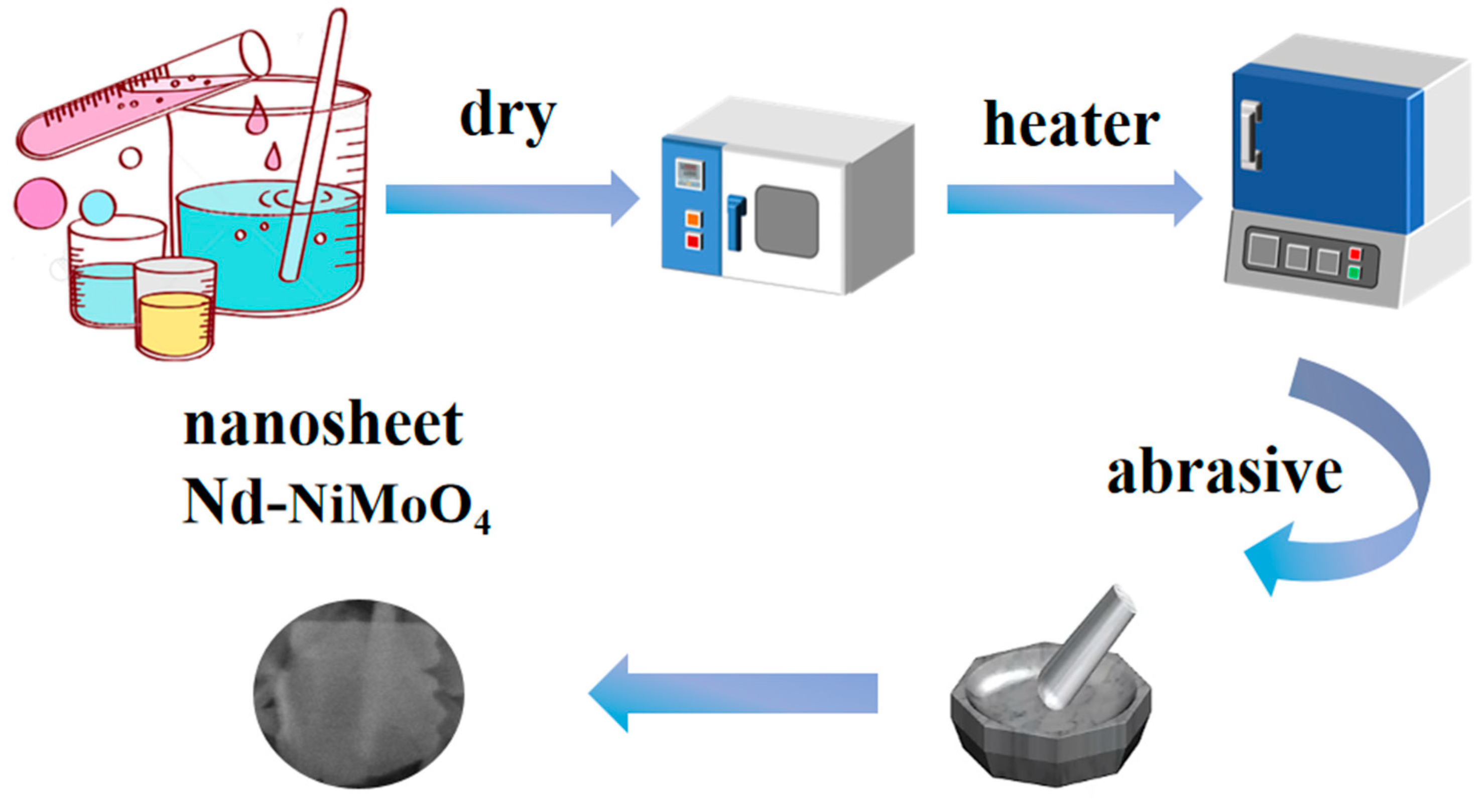
Using 17g ammonium molybdate tetrahydrate((NH4)6Mo7O24·4H2O), 29.1 g nickel nitrate (Ni(NO3)2·6H2O), 10 g citric acid (C6H8O7), and 10 g neodymium nitrate (Nd(NO3)3·6H2O) as the raw materials, 0.5% Nd-NiMoO4 nanosheets can be obtained according to the same preparation method as that in Section 2.2. If 10 g of neodymium nitrate (Nd(NO3)3·6H2O) is changed to 8 g of Nd(NO3)3·6H2O and 10 g of Nd(NO3)3·6H2O is changed to 12 g of Nd(NO3)3·6H2O, 0.2% of Nd-NiMoO4 nanosheets and 0.8% of Nd-NiMoO4 nanosheets can be obtained, respectively. The preparation of Nd-NiMoO4 nanomaterials in the experiment is shown in Figure 1.

Figure 1.
Schematic diagram of the preparation process of Nd-NiMoO4 electrode material.
2.4. Preparation of CNTs Electrodes
Firstly, 0.5 g of carbon nanotubes (CNTs) was taken and 60 mL of 80% nitric acid (HNO3) was added, and the mixture was heated at 80 °C for 18 h with continuous stirring. Subsequently, the mixture was cooled to room temperature and washed three times using ethanol and deionized water. Next, CNTs/CC electrodes were prepared by mixing 80% CNTs (by weight) and 10% carbon black, followed by mixing 10% carbon black and 10% polyvinylidene fluoride (PVDF). A small amount of ethanol was added to the above mixture, and the mixture was coated on the CC surface and dried at 90 °C for 6 h. The mixture was then dried at 90 °C for 6 h. The electrode was then coated on the CC surface and dried at 90 °C for 6 h.
2.5. Assembly of Supercapacitors
The asymmetric supercapacitor was installed with 0.5% Nd-NiMoO4 as positive electrode and CNTs as negative electrode. The matching equation of specific capacity, charge, and mass can be calculated by the following formula:
Cs (F/g) is the specific capacity, t (s) is the discharge time, i (A) is the current density, V (V) is the voltage drop, M (g) is the mass of the active substance, q is the charge on the flat plate, P (W/kg) is the power density, and E (Wh/kg) is the energy density.
3. Results and Discussion
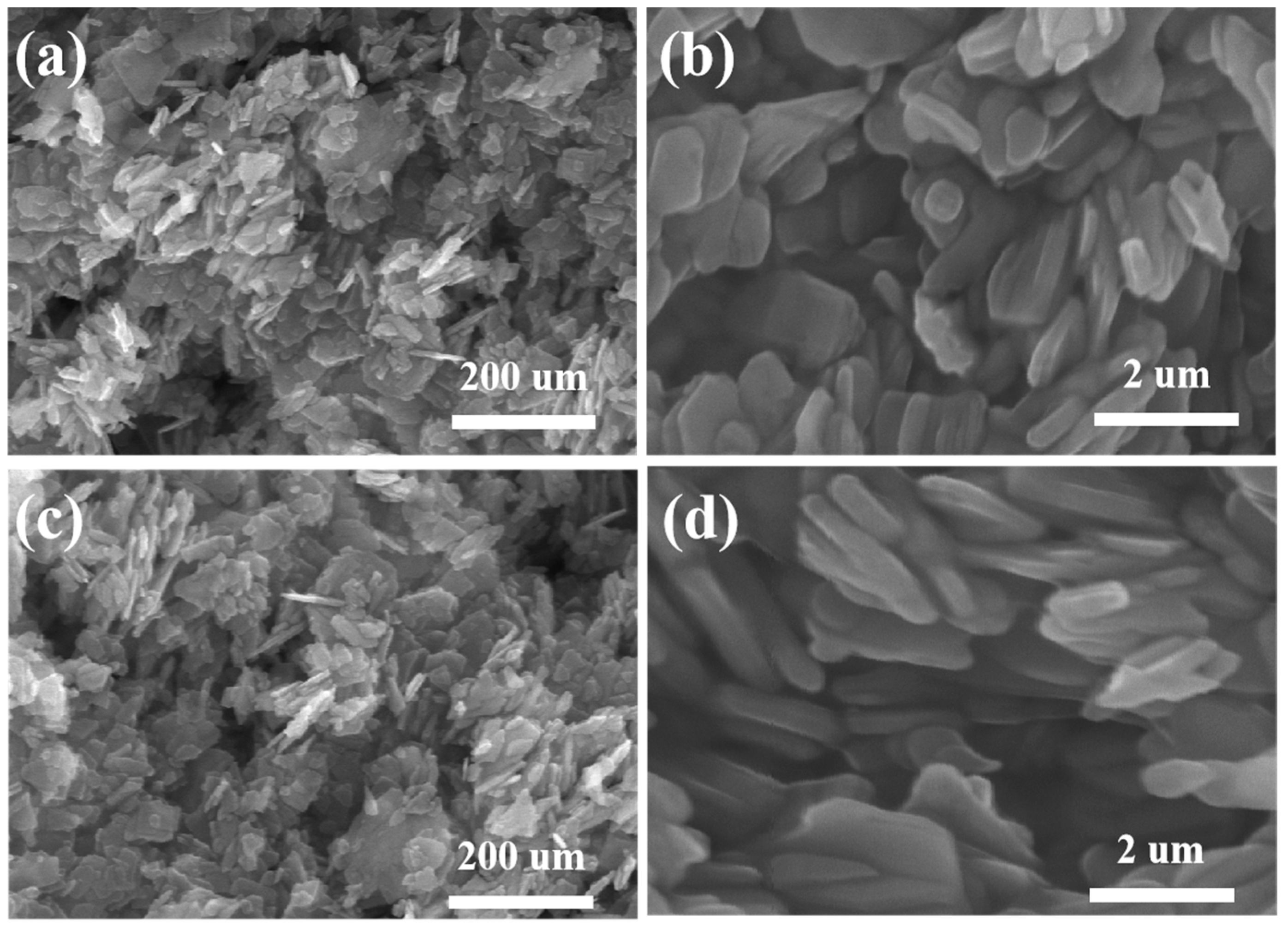
In the experiment, the micro-morphology of the prepared NiMoO4 and Nd-NiMoO4 electrode materials was tested by SEM, as shown in Figure 2. Figure 2a shows the SEM image of the NiMoO4 material, from which it can be seen that the structure is made up of lamellar nanostructures stacked on top of each other. Figure 2b is a high-magnification SEM image of the NiMoO4 material, from which it can be seen that the NiMoO4 lamellar nanomaterials obtained by the sol–gel method of preparation are interlaced with each other, forming a pore structure, which is conducive to increasing the specific surface area of the electrode material, allowing the electrode material to be in full contact with the electrolyte and, thus, accelerating the electrochemical reaction. Figure 2c shows the SEM image of the Nd-doped NiMoO4 material at low magnification, which shows a lamellar structure on the Nd-NiMoO4 material. These Nd-NiMoO4 lamellar nanostructures are of different sizes and have pores, as seen in Figure 2d. It was found that the observed phenomena of the material before and after doping with Nd rare earth elements showed almost no significant change.

Figure 2.
(a,b) are SEM images of NiMoO4 nanomaterials at different magnifications; (c,d) are SEM images of Nd-NiMoO4 nanomaterials at different magnifications.
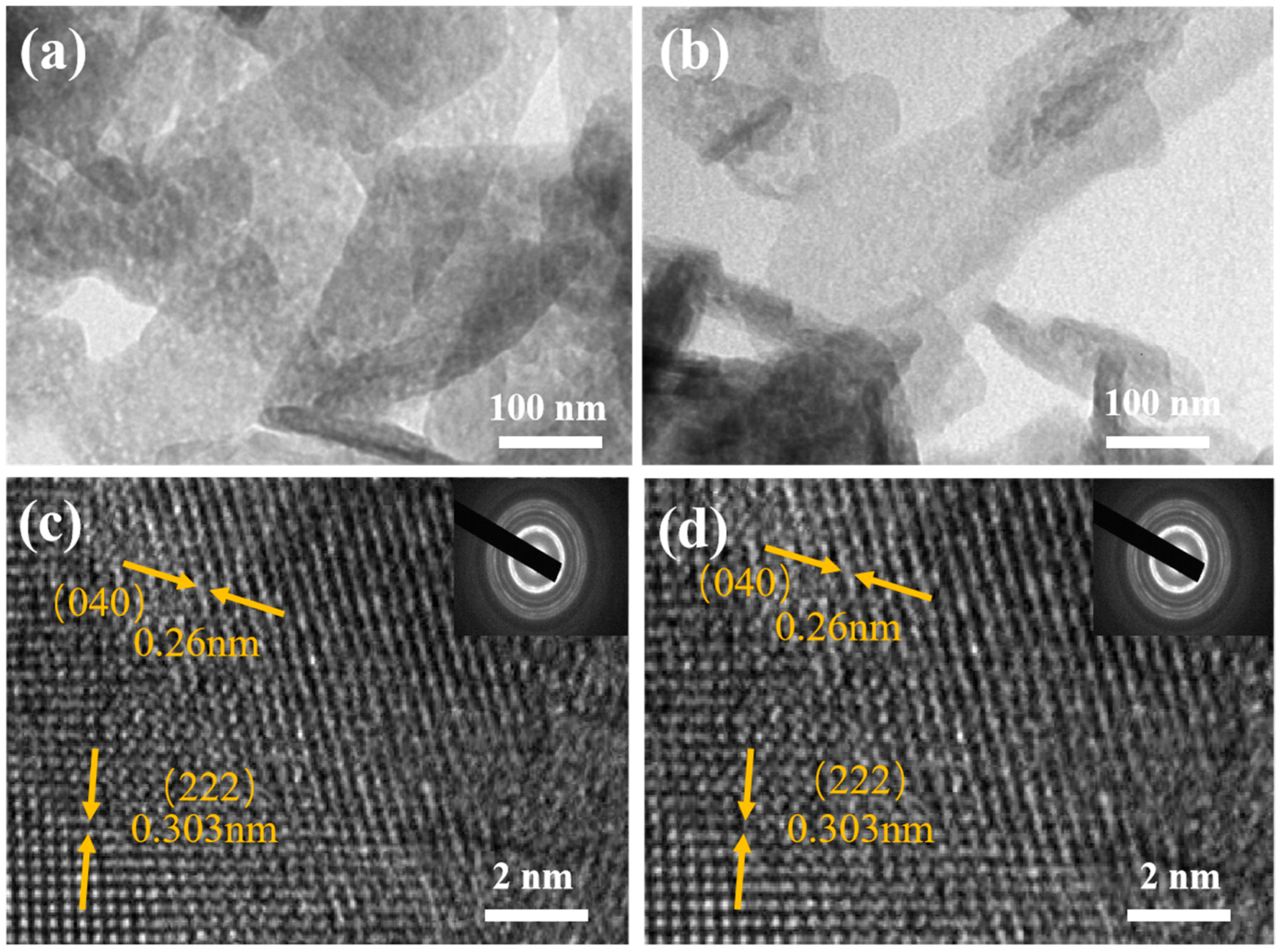
In order to further observe the microstructure of NiMoO4 and Nd-NiMoO4 nanomaterials, the materials were subjected to TEM tests. The microstructures of NiMoO4 and Nd-NiMoO4 nanomaterials are shown in Figure 3a,b, which show obvious layer structures that do not exist alone but are interwoven and connected together, which is in agreement with the SEM characterization tests’ results. We chose the regions in Figure 3a,b for high-resolution tests, and the results are shown in Figure 3c,d, where the lattice stripes have a crystallographic spacing of 0.26 nm and 0.303 nm, which correspond to the crystallographic planes (040) and (222), respectively. In the insets of Figure 3c,d, it can be seen that the material has a good diffraction ring, indicating that the prepared Nd-NiMoO4 is a polycrystalline material. It was found that the observed phenomena of the material hardly changed significantly before and after doping with Nd rare earth elements.
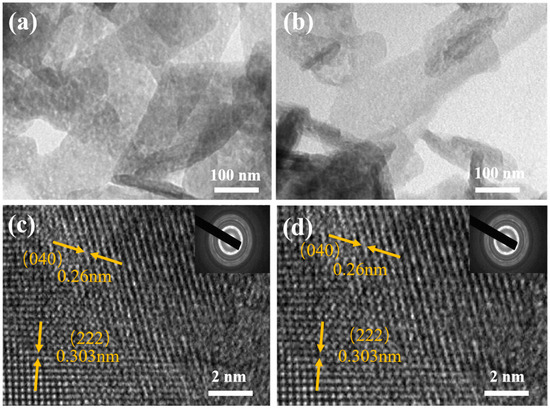
Figure 3.
(a,b) TEM images of NiMoO4, Nd-NiMoO4; (c,d) HRTEM images of NiMoO4, Nd-NiMoO4 (insert: the corresponding SAED plots).
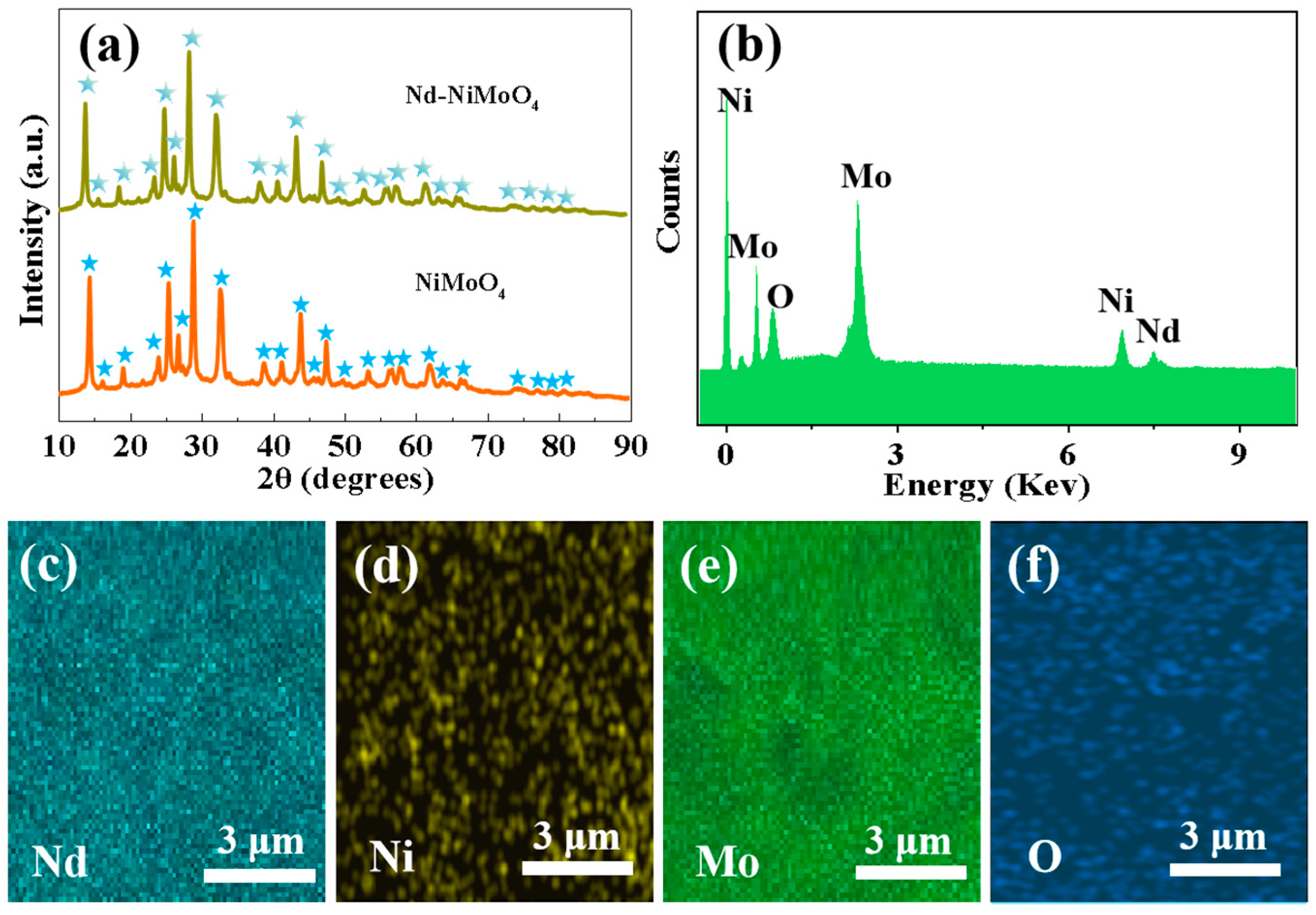
The material compositions of NiMoO4 and Nd-NiMoO4 nanosheets were characterized by XRD. Figure 4a shows the relationship between the XRD diffraction intensity and 2θ (10°–90°). In the XRD patterns of NiMoO4 and Nd-NiMoO4 nanosheets, there are slight, but not obvious, differences between the diffraction peaks of the two substances. The diffraction peak is narrow and sharp, and there are no other diffraction peaks, which conforms to the typical peak (PDF, card No. 13-0128), indicating that the prepared product has a high degree of crystallization and high product purity. Figure 4b shows the EDS test results of the Nd-NiMoO4 mesh structure, indicating that the material contains only Nd, Ni, Mo element, O element, and no other impurity elements. Figure 4c–f show the TEM mapping of Nd-NiMoO4 nanomaterials, in which it can be seen that the prepared material contains four elements, Nd, Ni, Mo, and O. The TEM test results are in agreement with the results of the EDS elemental fractions, which indicate that the prepared material does not contain the presence of other impurity elements.
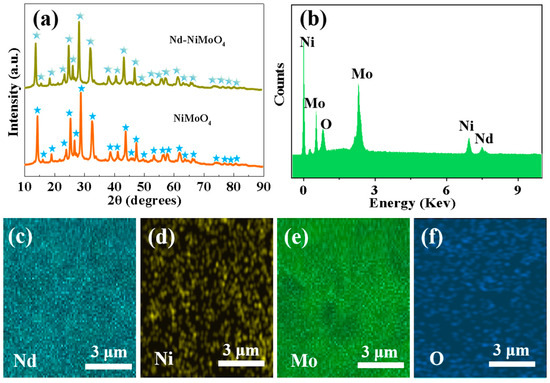
Figure 4.
(a) XRD spectra of NiMoO4, Nd-NiMoO4 nanomaterials; (b) EDS spectra of Nd-NiMoO4 nanomaterials; (c–f) TEM mapping of Nd-NiMoO4 nanomaterials.
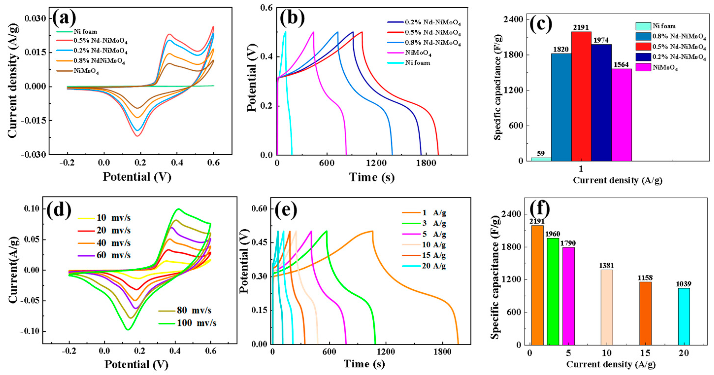
As mentioned above, in order to explore the electrochemical properties of the prepared samples, Pt was used as the counter electrode, Hg/HgO was used as the reference electrode, the experimentally prepared material was used as the working electrode, and potassium hydroxide was used as the electrolyte. CV (the CV curves are cyclic voltammetry) and GCD (GCD is constant current charge/discharge test) curves were measured in aqueous solution of a 3 M KOH three-electrode system (Figure 5). Figure 6a shows the cyclic voltammetry curves of specific capacities for different materials and doping percentages under a voltage window of −0.2 to 0.6 V. It can be clearly seen from the figure that the specific capacity of the material reaches the maximum when the doped Nd percentage is 0.5%. Figure 6b shows the charge and discharge curves of different materials. It can be seen that the curves have good symmetry, and the 0.5% Nd-NiMoO4 material shows the best discharge performance. In addition, according to Formula (2), we calculated the specific capacitance of nickel foam and materials with different doping percentages when the current density is 1 A/g, with the results shown in Figure 6c. It can be observed from the figure that when the doped Nd percentage is 0.5%, the specific capacitance of the material reaches the maximum. In order to further study the properties of 0.5% Nd-NiMoO4 material, we plotted its cyclic voltammetry curves at different scanning rates (10, 20, 40, 60, 80, 100 mV/s), with the results shown in Figure 6d. It can be seen from the figure that all the samples have similar CV curve shapes at the sweep speed. Among them, in the potential range of 0.3 V to 0.6 V, a typical oxidation peak can be clearly observed, which is formed by Ni2+ being oxidized to Ni3+, losing an electron. At the same time, in the potential range of 0.0 V to 0.3 V, the presence of a typical reduction peak can be clearly observed—due to the reduction of Ni3+ to Ni2+, an electron is obtained. This shows that the Nd-NiMoO4 electrode material has a REDOX reaction, which shows an obvious charge and discharge storage mechanism of pseudocapacitance. Finally, we performed constant current charge/discharge experiments on the 0.5% Nd-NiMoO4 material and recorded the device voltages at current densities of 1, 3, 5, 10, 15, and 20 A/g, respectively, with the results shown in Figure 6e. Based on these results, we calculated the specific capacitance of 0.5% Nd-NiMoO4, as shown in Figure 4f. It can be seen that the specific capacitances of the 0.5% Nd-NiMoO4 devices are 2191, 1960, 1790, 1381, 1158, and 1039 F/g at current densities of 1, 3, 5, 10, 15, and 20 A/g. These experimental results show that at 0.5% Nd doping, the NiMoO4 material displays excellent specific capacity and specific capacitance performance. The electrochemical properties of the 0.5% Nd-NiMoO4 nanomaterials and the comparison with references are given in Table 2.
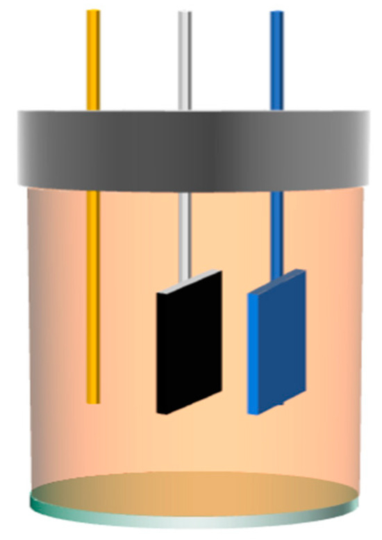
Figure 5.
Schematic diagram of three electrodes.

Figure 6.
(a) Cyclic voltammetry curves of different materials; (b) charge–discharge curves of different materials at a current density of 1 A/g; (c) comparison of the specific capacitance of different materials at 1 A/g; (d) cyclic voltammetry curves of the materials at different scanning rates; (e) charge–discharge curves of the materials at different current intensities; and (f) specific capacitance diagrams of the materials at different current densities.
Table 2.
Comparison of electrode material properties with literature.
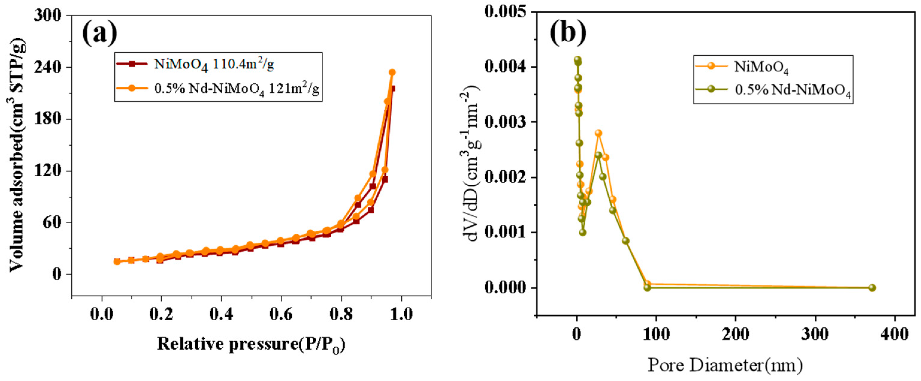
The specific surface area and pore size of the material have an important effect on the electrochemical performance. The increase of pore volume and pore size will increase the specific surface area, and the increase of specific surface area will expose more active sites of the catalyst, thus improving the catalytic activity, and thus improving the electrochemical performance [18,19]. The nanostructured rare earth material raises its surface area to volume ratio to a very large level quantity, which allows it to expose more active sites. The exposure of the active site to a high-energy crystal plane with a specific form allows the material to be easily reduced and oxidized, resulting in a longer cycle life. Figure 7a shows the N2 absorption and desorption curve of the material before and after doping with rare earth elements. The specific surface area of the material before doping is 110.4 m2/g, and that of the material after doping is 121 m2/g. With the gradual increase of the relative pressure, the adsorption volume increases and reaches the maximum value at 1.0P/P0. After doping, the specific surface area of the material is larger. Figure 7b shows that the pore size of the material before and after doping with rare earth elements is uniform, mainly distributed at 27 nm. Compared with the curve before doping, it can be found that materials doped with rare earth elements have richer pore size. For Nd-NiMoO4, higher specific surface area, together with more abundant pores, can accelerate ion and electron transfer and promote electrochemical reaction. All of these are beneficial to intensify the electrochemical performance of Nd-NiMoO4.
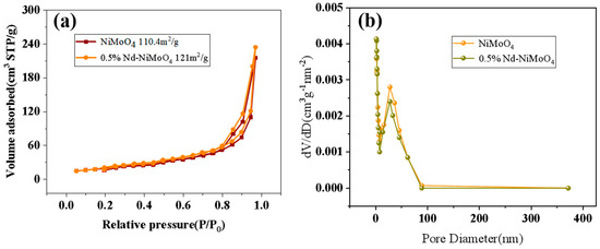
Figure 7.
(a) Comparison of N2 adsorption/desorption curves of NiMoO4, 0.5% Nd-NiMoO4; (b) comparison of pore size distribution curves of NiMoO4, 0.5% Nd-NiMoO4.
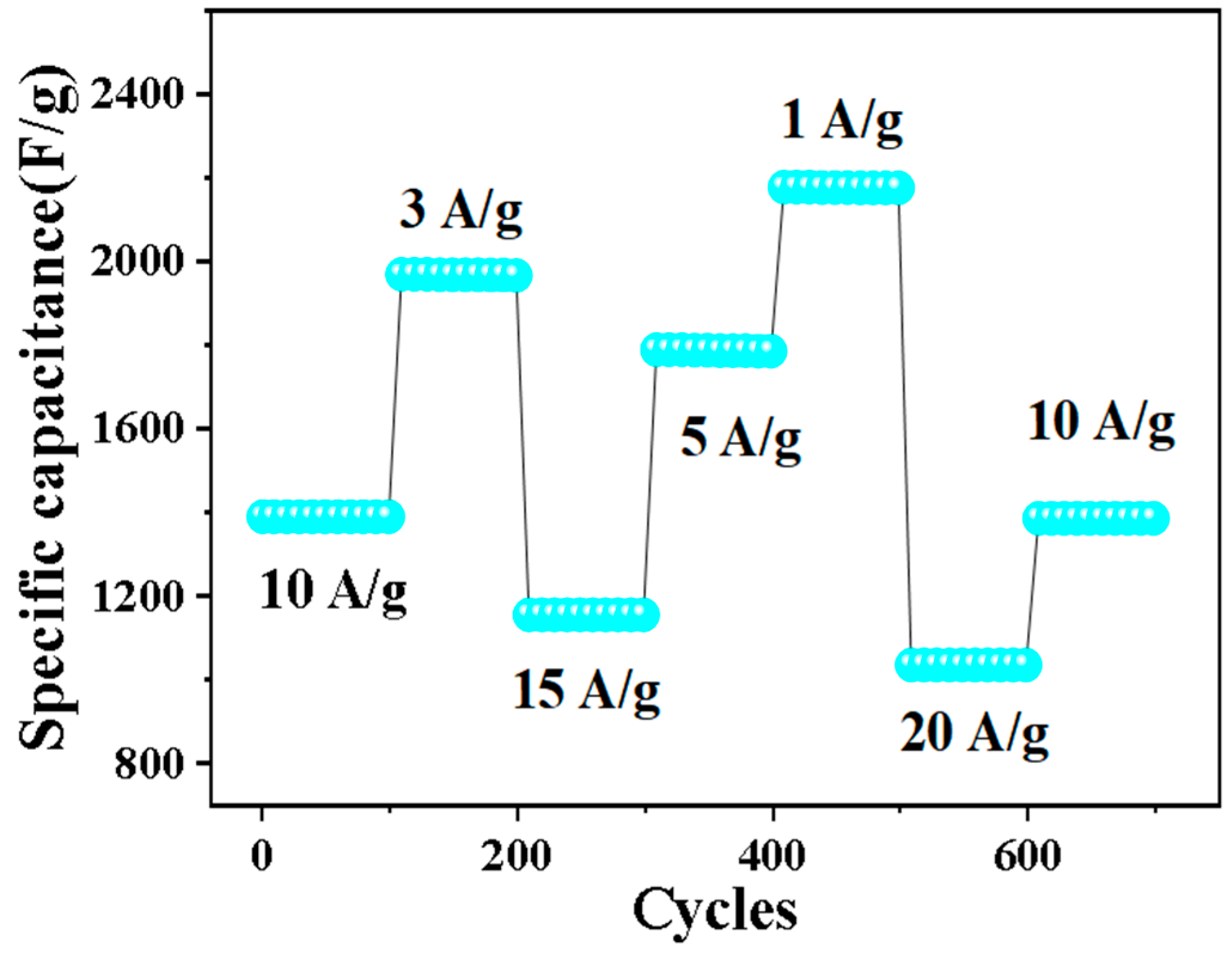
Cyclic stability is also an important factor in evaluating electrochemical performance. Figure 8 shows the cyclic stability test of 0.5% Nd-NiMoO4 material at different current densities. When the charge and discharge density is 10 A/g, the material shows a stable specific capacity of 1381 F/g in the first 100 cycles. Over the next 600 cycles, the current density changes in turn. When the current density is restored to 10 A/g, the specific capacity is 1372 F/g and the loss is very small, indicating that the structure has excellent cyclic stability.

Figure 8.
Rate and periodic properties of Nd-NiMoO4 at different current densities.
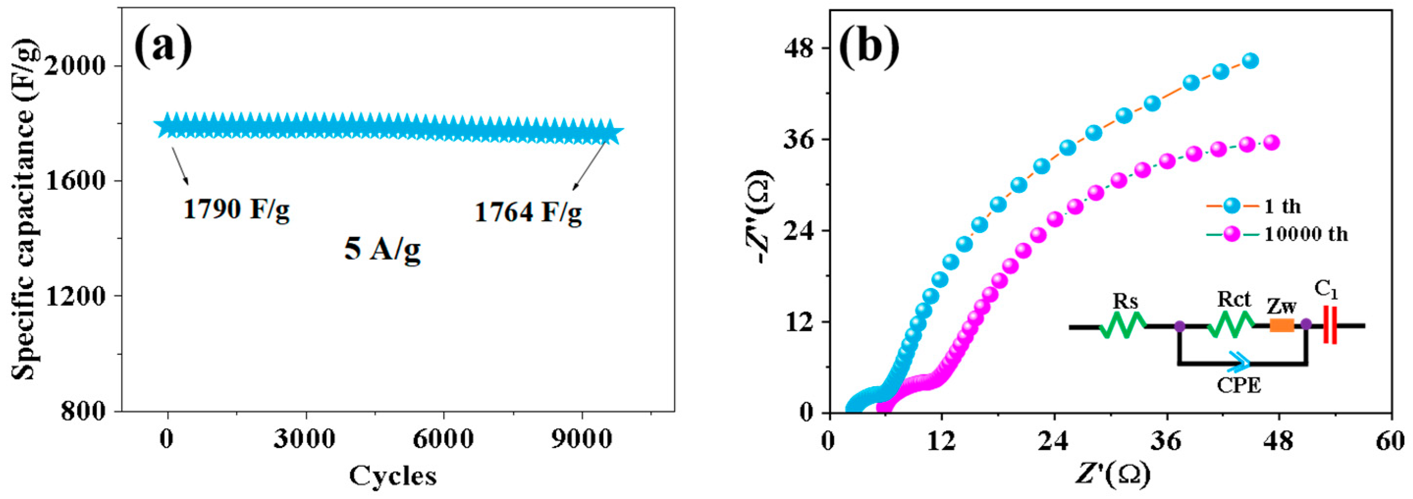
Figure 9a demonstrates the graph of 0.5% Nd-NiMoO4 after 10,000 cycles. From the graph, it can be observed that the capacity decay of the material after 5000 cycles is very small, which indicates its good cycling stability. Figure 9b shows the Nyquist diagram of the sample after the 1st and 3000th cycles. The curve in the diagram consists of high frequencies and low frequencies, with the high-frequency region representing the impedance of ions passing through the surface film of the electrode material and the low-frequency region representing the charge transfer impedance [20]. In general, the value of the horizontal axis represents Rs, and its value can be read according to the intercept of the curve and the horizontal axis, so the Rs value of the 10,000th cycle and the first cycle are 5.89 Ω and 2.62 Ω, respectively, which proves that the Nd-NiMoO4 material has good electrical conductivity. The diameter of a curve similar to a semicircle in the high-frequency region is expressed as Rct, and the value of Rct is related to the diameter of the semicircle. It can be seen from the figure that the diameter of the semicircle arc in the 3000th cycle is larger than that in the first cycle, and the Rct values in the 3000th cycle and the first cycle are 12.3 Ω and 7.2 Ω, respectively. It is shown that Nd-NiMoO4 has good charge transfer ability and can react to the capacitance of the prepared sample to a certain extent. After the first cycle, the diffusion resistance along the ideal line of the virtual axis is low. After 10,000 cycles, the Rs of the electrode increases slightly, which may be due to the corrosion of the nanostructure by dissolved oxygen in the electrolyte during the charge–discharge process, resulting in the loss of adhesion of some deposited active substances. The charge transfer resistance changes little, indicating that the 0.5% Nd-NiMoO4 nanostructure has long-term electrochemical stability.
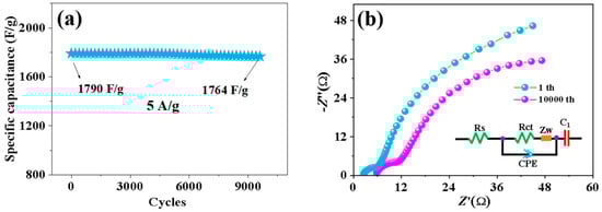
Figure 9.
(a) Stability test for 10,000 cycles at a current density of 5 A/g; (b) Nyquist plots for the first and 10,000th cycles.
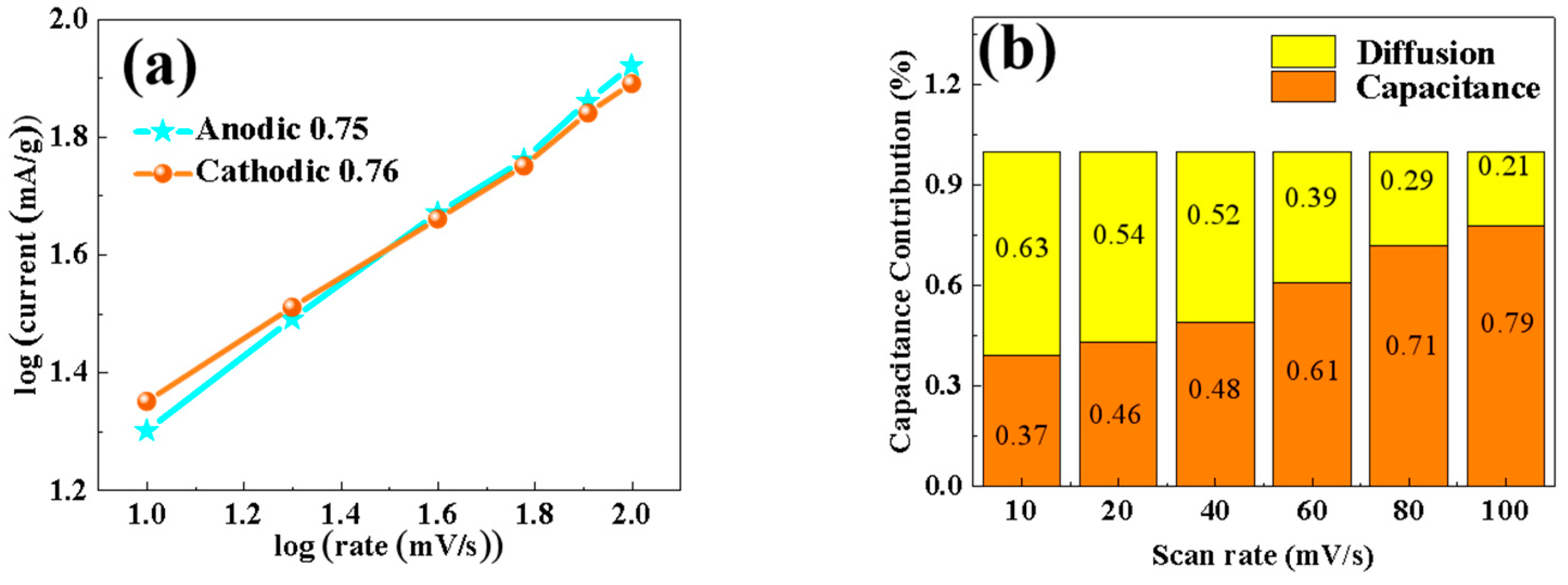
In order to study the diffusion effect and dynamic behavior of the material, the CV curve in the figure was used to perform linear quasi-merging calculations of log(i) and log(v), with the results shown in Figure 10. In the CV test, different peak current values (i, mA) are obtained at different voltage sweep rates (v, mV/s). By corresponding the scanning rate to the peak current response, the diffusion behavior or the pseudocapacitance behavior of the battery during charging and discharging can be distinguished. If it is a battery behavior, the peak current i varies with power of the scanning voltage v, that is, the process is diffusion control. If the behavior is pseudocapacitive, the peak current i varies linearly with the scanning voltage v, that is, the process is capacitive control. The value of b was calculated according to the formula i = avb—with a b value of 0.5, the materials are dominated by the diffusion control mechanism, and with a b value of 1, the materials are dominated by the capacitive mechanism [21]. In this paper, the b values of anode and cathode materials are closer to 1, which indicates that, the porous 0.5% Nd-NiMoO4 nanorods are mainly controlled by the pseudocapacitance of the surface, supplemented by the diffusion control, and the two control modes act synergistically. Figure 10b shows the calculation result of the contribution rate of pseudocapacitance behavior to charge storage. By connecting a number of specific voltages (V, mV) with Kν (i, mA) through smooth curves, nonlinear fitting is carried out, and then the area of the fitted closed curve is obtained using an integral method, and then the area of the CV curve at a specific scanning rate is obtained using an integral method. Dividing the area of the fitted curve by the area of the CV curve provides the pseudocapacitance contribution rate at a specific scanning rate. The contributions of the two mechanisms are obtained quantitatively by the formula i = k1v + k2v1/2 [22]. The pseudocapacitance control increases gradually with the scan rate, and when the scan rate is increased to 100 mV/s, the contribution of the pseudocapacitance control reaches 79%, and that of the diffusion control is 21%. It is shown that the 0.5% Nd-NiMoO4 material has the kinetic behavior of pseudocapacitance.
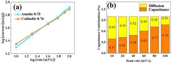
Figure 10.
(a) b-value of 0.5% Nd-NiMoO4 electrode material; (b) contribution of diffusion control and capacitance control of 0.5% Nd-NiMoO4 electrode material.
Figure 11 shows the corresponding reaction mechanism diagram of the electrode material. From the relevant literature [23,24], the reasons for the excellent electrochemical performance of 0.5% Nd-NiMoO4 electrode material are summarized and analyzed: (1) The porous nanosheet structure has a large specific surface area, which provides for the reaction of the rich active sites, increases the contact area between the electrode and the electrolyte, and accelerates the rate of the reaction. (2) The NiMoO4 material has strong redox activity, as well as excellent reversible charge storage properties. (3) The Nd-NiMoO4 nanosheet structure synergizes well with the excellent electrochemical properties of the material itself, giving the material excellent electrochemical properties.
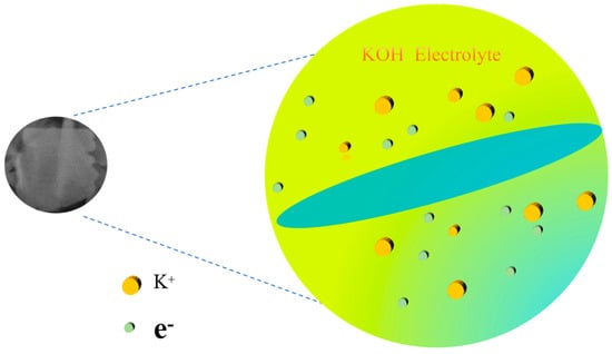
Figure 11.
Corresponding reaction mechanism diagram of 0.5% Nd-NiMoO4 nanosheets.
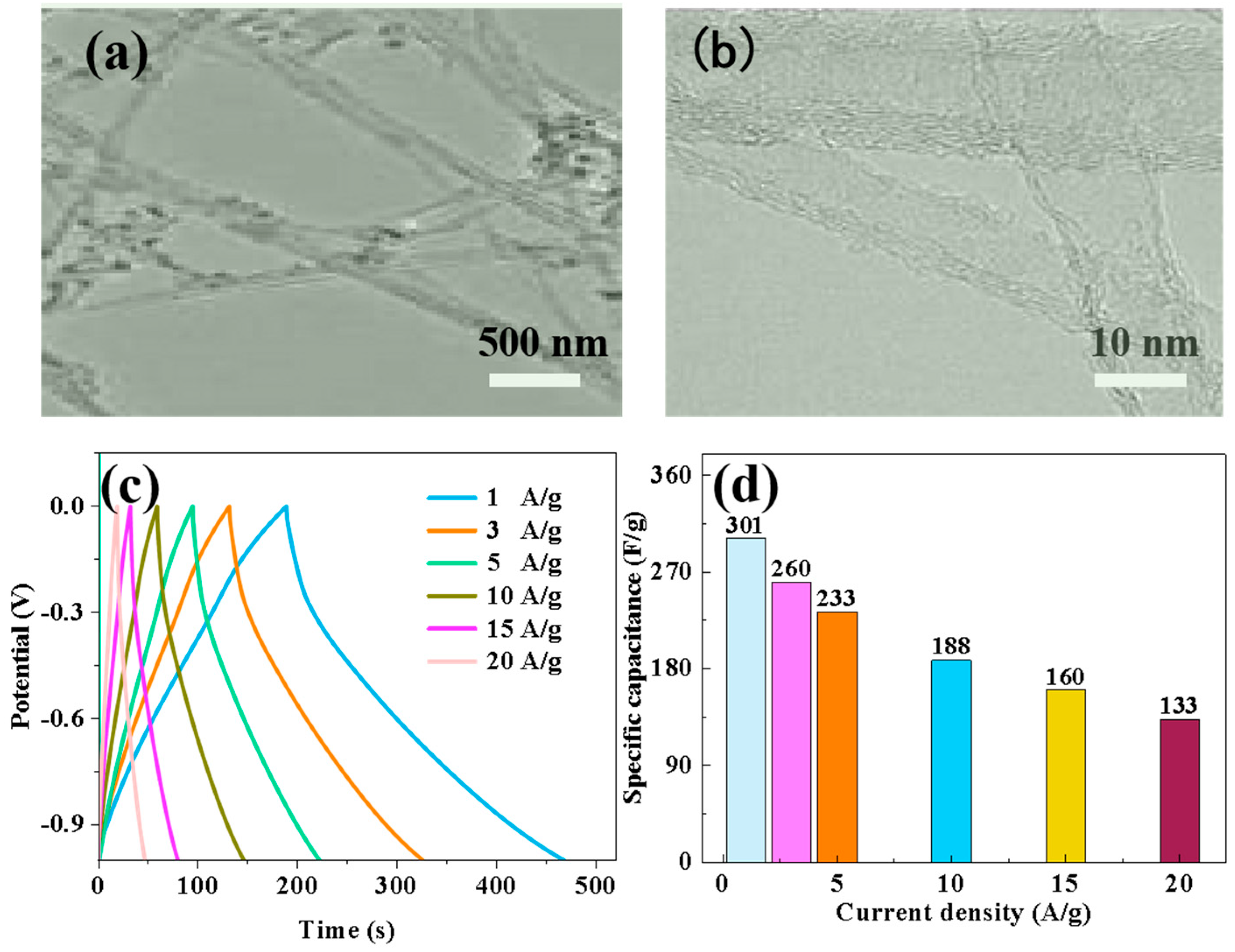
The matching assembly of Nd-NiMoO4 material with CNTs for asymmetric devices was also investigated in the experiments, and we used Nd-NiMoO4 as the positive electrode material and CNTs as the negative electrode material. Firstly, the electrochemical performance of CNTs as negative electrode materials under different currents was explored, and in order to investigate the microstructure of CNTs, TEM images were analyzed. As shown in Figure 12a,b, the carbon nanotubes were interwoven in a mesh shape. Subsequently, the electrochemical performance of the CNT anode materials at different current densities was further explored, and constant current charge/discharge and specific capacity tests were carried out. Figure 12c shows the charge/discharge test curves of the CNT materials at different current densities, and the characteristic curves are in the form of triangles, which indicates that the material has a good charging/discharging performance. The specific capacities of CNT materials were calculated according to the charge/discharge curves and Equation (2). As shown in Figure 12d, the specific capacities of CNTs materials tested at current densities of 1 A/g, 3 A/g, 5 A/g, 10 A/g, 15 A/g, and 20 A/g were 301 F/g, 260 F/g, 233 F/g, 188 F/g, 160 F/g, and 133 F/g. The experimental data show that that the specific capacity decreases with increasing current density, which is due to the combination of a few materials not being able to fully participate in the reaction and a few irreversible changes during the increase in current.
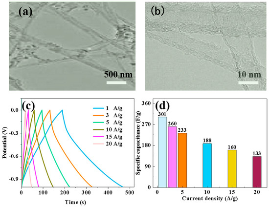
Figure 12.
(a,b) TEM images of CNT materials at different magnifications; (c) charge–discharge curves of CNT electrodes at different current densities; (d) specific capacity curves of CNT electrodes at different current densities.
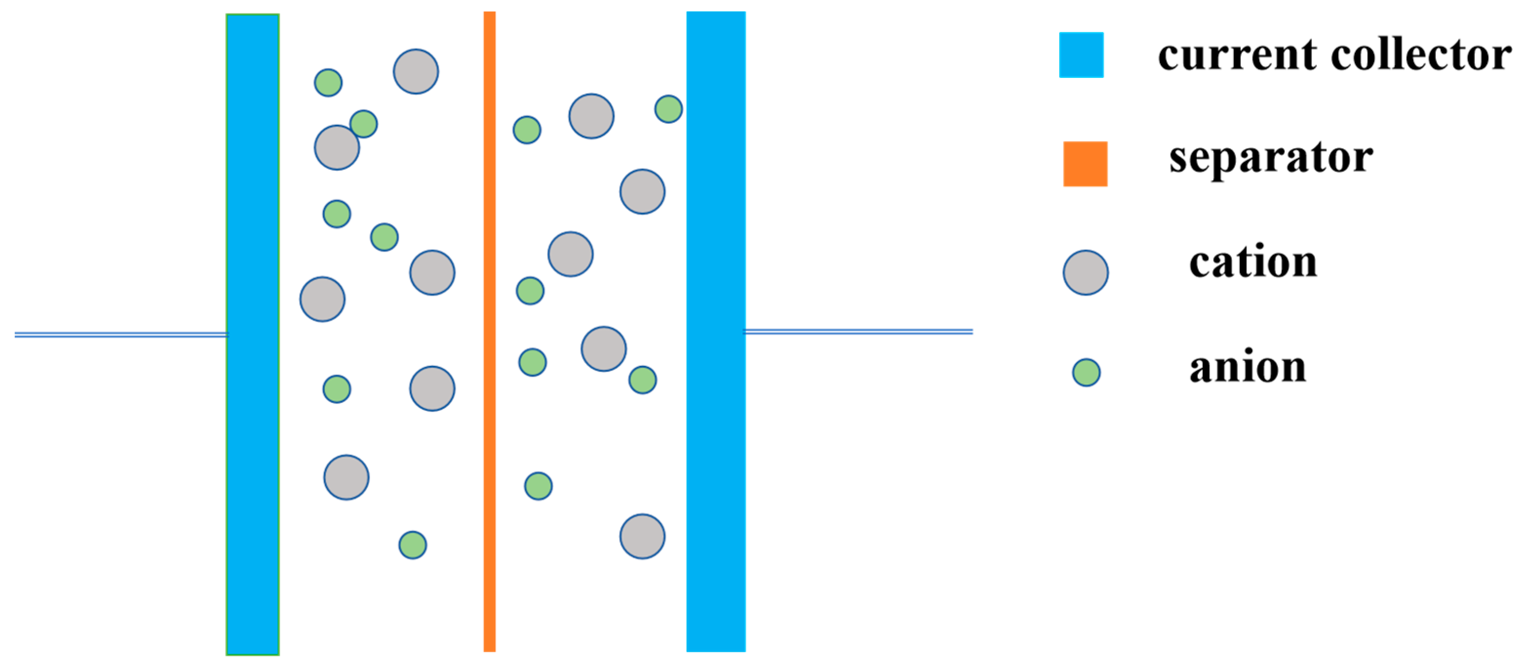
In order to explore the performance of electrode materials in practical applications, a supercapacitor device was assembled with Nd-NiMoO4 as the positive electrode material, CNT as the negative electrode material, and KOH as the electrolyte, as shown in Figure 13, and its electrochemical performance was studied. When the current density is 1 A/g, the specific capacitance of the positive and negative materials is 2182 F/g and 301 F/g, respectively. The voltage windows are 0.8 V and 1.0 V, respectively. According to the mass matching Formula (3), the material mass ratio of the anode and cathode of the asymmetric device was calculated to be M+/M− ≈ 1/5.
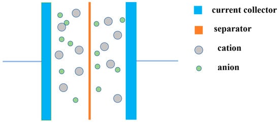
Figure 13.
Supercapacitor device diagram.
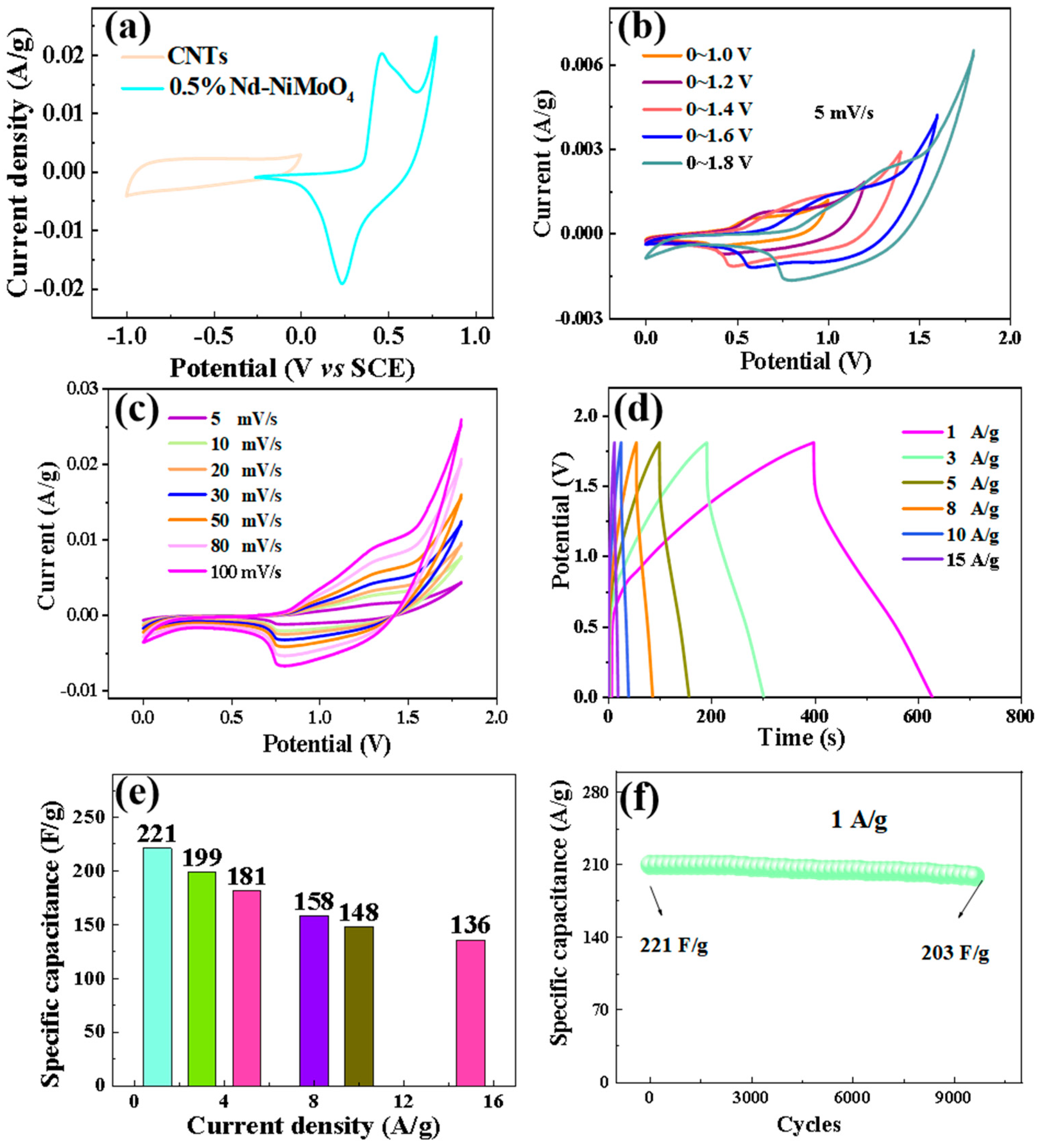
The CV curves of Nd-NiMoO4 and CNT materials are shown in Figure 14a, showing that the maximum voltage of Nd-NiMoO4 material is 0.8 V and the minimum voltage of CNT material is −1.0 V at the sweep rate of 5 mV/s. The windowed value voltage of the difference between the positive voltage and the negative voltage is the value of the voltage of the asymmetric device. Therefore, the theoretical voltage of the device prepared from Nd-NiMoO4 and CNTs is 1.8 V (1.0 V + 0.8 V = 1.8 V). Figure 14b shows the CV curves of the device under different voltage windows at a sweep rate of 5 mV/s. The figure shows that the curves show a closed feather shape at different voltages and the shape of the curves does not change significantly with the gradual increase of the voltage up to 1.8 V. Therefore, the stabilized voltage range of the device is 1.8 V, which is in agreement with the theoretical voltage value. Figure 14c shows the CV curves of Nd-NiMoO4//CNTs at different scan rates, wherein the curves increase proportionally with the increase of the scan rate, the shape is not significantly different, and the voltage window is stabilized between 1.8 V. This indicates that with the increase of the scan rate, the rate of the electrochemical reaction is accelerated, the charge storage is enhanced, and the device has a better stabilization performance in the application. Charge–discharge tests were performed on the devices at different currents, as shown in Figure 14d, wherein the curves are triangular with good symmetry, indicating that the devices have good electrochemical performance. According to Equation (3), the specific capacity of the devices at different currents was calculated, as shown in Figure 14e, wherein the specific capacity of the asymmetric device Nd-NiMoO4//CNTs is 221 F/g at a current density of 1 A/g, and the device still has a high specific capacity of 136 F/g when the current density reaches 15 A/g, which indicates that the as-prepared device has a good electrochemical performance. Figure 14f shows the cycling stability test of the device at a current density of 1 A/g. After 10,000 cycles, the specific capacity decreases from the initial 221 F/g to 203 F/g, with a capacitance retention of 91.9%.
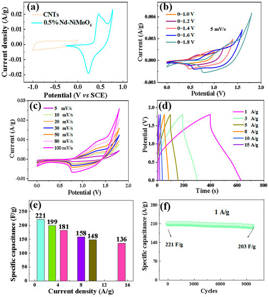
Figure 14.
(a) CV curves of 0.5% Nd-NiMoO4, CNTs, (b) CV curves of the devices under different windows at a sweep rate of 5 mV/s, (c) CV curves of 0.5% Nd-NiMoO4//CNTs devices at different sweep rates, (d) charge/discharge curves of 0.5% Nd-NiMoO4//CNTs devices at different current densities, (e) specific capacitance curves of 0.5% Nd-NiMoO4//CNTs at different current densities, (f) cycling stability test plot of the device at a current density of 1 A/g.
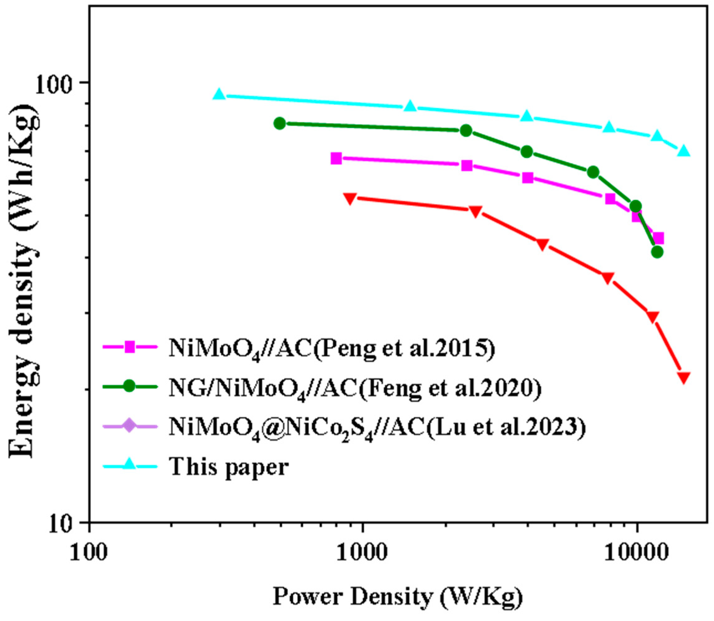
We calculated the energy density and power density of the devices according to Equations (4) and (5) and compared the fabricated Nd-NiMoO4//CNTs ASC devices with other energy storage devices, as shown in Figure 15. It can be seen that the Nd-NiMoO4//CNTs asymmetric device can provide a maximum energy density of 73.5 Wh/kg and a power density of 902 W/kg, and the comparison concludes that the performance of the devices studied in this paper is significantly better than the energy density and power density values of other energy storage devices [8,25,26] listed in the literature. It has better practical application value compared to other devices and has better development potential.

Figure 15.
Ragone plots of 0.5% Nd-NiMoO4//CNTs devices compared to other devices [8,25,26].
4. Conclusions
In summary, sheet Nd-NiMoO4 electrode materials doped with rare earth were prepared via a gel method, and the effects of different contents of rare earth elements on the properties of electrode materials were studied. The results show that the electrochemical performance of the samples prepared at 0.5% Nd content is the best. When the current density is 1 A/g, the specific capacity reaches 2182 F/g, and when the current density is 5 A/g, after 10,000 cycles, the specific capacity is reduced from 1790 F/g to 1764 F/g and the capacitance retention rate is 98.5%. Then, the 0.5% Nd-NiMoO4 material and CNTs material were assembled into asymmetric capacitor devices, with results showing that the specific capacitance of asymmetric devices reaches up to 210 F/g at 1 A/g current density. At 1 A/g current density, after 10,000 cycles, the specific capacitance is reduced from 221 F/g to 203 F/g, and the specific capacitance retention rate is up to 91.9%, which has excellent practical application value. At the same time, the prepared device has a high energy density of 73.5 Wh/kg (power density of 902 W/Kg). It provides a practical reference value for the preparation of doping materials.
Author Contributions
L.A. carried out the experiments and wrote the manuscript, and T.M. designed this experiment and wrote the manuscript and other analyses. Y.N. and J.W. carried out the characterization tests, analyzed, and wrote the results. All authors have read and agreed to the published version of the manuscript.
Funding
National Natural Science Foundation of China (No. 52002099); Fund of State Key Laboratory of Efficient Utilization of Coal and Green Chemical Industry (Grant No. 2022-K74); Heilongjiang Provincial Youth Scientific Research Project (No. 2019DS084).
Institutional Review Board Statement
Not applicable.
Informed Consent Statement
Not applicable.
Data Availability Statement
Data are contained within the article.
Conflicts of Interest
The authors declare no conflicts of interest.
References
- Yang, A.; Wang, H.; Li, B.; Tan, Z. Capacity optimization of hybrid energy storage system for microgrid based on electric vehicles’ orderly charging/discharging strategy. J. Clean. Prod. 2023, 411, 137346. [Google Scholar] [CrossRef]
- Abbas, Q.; Mirzaeian, M.; Hunt, M.R.C.; Pater, H.; Rizwan, R. Current state and future prospects for electrochemical energy storage and conversion systems. Energies 2020, 13, 5847. [Google Scholar] [CrossRef]
- Ren, G.; Wang, H.; Chen, C.; Wang, J. An energy conservation and environmental improvement solution-ultra-capacitor/battery hybrid power source for vehicular applications. Sustain. Energy Technol. Assess. 2021, 4, 100998. [Google Scholar] [CrossRef]
- Vishwanathan, S.; Matte, H.S.S.R. Low temperature synthesis of crystalline pyrite FeS2 for high energy density supercapacitors. Chem. Commun. 2023, 59, 9263–9266. [Google Scholar] [CrossRef] [PubMed]
- Meghanathan, K.L.; Parthibavarman, M.; Sharmila, V.; Joshua, J.R. Metal-organic framework-derived Nickle Tellurideporous structured composites electrode materials for asymmetric supercapacitor application. J. Energy Storage 2023, 72, 108665. [Google Scholar] [CrossRef]
- Liang, S.; Wang, H.; Li, Y.; Qin, H.; Luo, Z.; Huang, B.; Zhao, X.; Zhao, C.; Chen, L. Rare-earth based nanomaterials and their composites as electrode materials for high performance supercapacitors: A review. Sustain. Energy Fuels 2020, 4, 3825–3847. [Google Scholar] [CrossRef]
- Arunachalam, S.; Kirubasankar, B.; Pan, D.; Hu, L.; Yan, C.; Guo, Z.; Angaiah, S. Research progress in rare earths and their composites based electrode materials for supercapacitors. Green Energy Environ. 2020, 5, 259–273. [Google Scholar] [CrossRef]
- Feng, X.; Ning, J.; Wang, D.; Zhang, J.; Xia, M.; Wang, W.; Hao, Y. Heterostructure arrays of NiMoO4 nanoflakes on N-doping of graphene for high-performance asymmetric supercapacitors. J. Alloys Compd. 2020, 816, 152625. [Google Scholar] [CrossRef]
- Zhang, Y.; Chang, C.; Jia, X.; Huo, Q.; Gao, H.; Yan, J.; Zhang, A.; Ru, Y.; Mei, H.; Gao, K.; et al. Morphology-dependent NiMoO4/carbon composites for high performance supercapacitors. Inorg. Chem. Commun. 2020, 111, 107631. [Google Scholar] [CrossRef]
- Sivakumar, P.; Raj, C.J.; Park, J.W.; Jung, H. Facile fabrication of flower-like binary metal oxide as a potential electrode material for high-performance hybrid supercapacitors. Ceram. Int. 2022, 48, 9459–9467. [Google Scholar] [CrossRef]
- Theerthagiri, J.; Durai, G.; Tatarchuk, T.; Sumathi, M.; Kuppusami, P.; Qin, J.; Yongchoi, M. Synthesis of hierarchical structured rare earth metal–doped Co3O4 by polymer combustion method for high performance electrochemical supercapacitor electrode materials. Ionics 2020, 26, 2051–2061. [Google Scholar] [CrossRef]
- Bokov, D.; Turki Jalil, A.; Chupradit, S.; Suksatan, W.; Javed Ansari, M.; Shewael, I.H.; Valiew, G.H.; Kianfar, E. Nanomaterial by sol-gel method: Synthesis and application. Adv. Mater. Sci. Eng. 2021, 2021, 5102014. [Google Scholar] [CrossRef]
- Murugan, E.; Govindaraju, S.; Santhoshkumar, S. Hydrothermal synthesis, characterization and electrochemical behavior of NiMoO4 nanoflower and NiMoO4/rGO nanocomposite for high-performance supercapacitors. Electrochim. Acta 2021, 392, 138973. [Google Scholar] [CrossRef]
- Yousefipour, K.; Sarraf-Mamoory, R.; Maleki, A.C. A new strategy for the preparation of multi-walled carbon nanotubes/NiMoO4 nanostructures for high-performance asymmetric supercapacitors. J. Energy Storage 2023, 59, 106438. [Google Scholar] [CrossRef]
- Ren, B.; Wang, X.; Zhang, X.; Wang, B.; Li, Y.; Zeng, X.; Zhang, X.; Fan, M.; Yang, X. Designed formation of hierarchical core-shell NiCo2S4@NiMoO4 arrays on cornstalk biochar as battery-type electrodes for hybrid supercapacitors. J. Alloys Compd. 2023, 937, 168403. [Google Scholar] [CrossRef]
- Abbas, Y.; Yun, S.; Javed, M.S.; Chen, J.; Tahir, M.F.; Wang, Z.; Yang, C.; Arshad, A.; Hussain, S. Anchoring 2D NiMoO4 nano-plates on flexible carbon cloth as a binder-free electrode for efficient energy storage devices. Ceram. Int. 2020, 46, 4470–4476. [Google Scholar] [CrossRef]
- Sun, Y.; Liu, Z.; Zheng, X.; Wang, C.; Wang, J.; Jiang, M.; Jiang, D.; Liu, J. Construction of KCu7S4@NiMoO4 three-dimensional core-shell hollow structure with high hole mobility and fast ion transport for high-performance hybrid supercapacitors. Compos. Part B Eng. 2023, 249, 110409. [Google Scholar] [CrossRef]
- Li, J.; Lin, Q.; Wang, Z.; Du, A.; Luo, H.; Liu, Y.Q. Hierarchical porous carbon with high specific surface area and superb capacitance made from palm shells for supercapacitors. Diam. Relat. Mater. 2023, 135, 109852. [Google Scholar] [CrossRef]
- Li, P.; Ruan, C.; Xu, J.; Xie, Y. Supercapacitive performance of CoMoO4 with oxygen vacancy porous nanosheet. Electrochim. Acta 2020, 330, 135334. [Google Scholar] [CrossRef]
- Wang, J.; Wang, G.; Wang, S.; Hao, T.; Hao, J. Coupling of Nd doping and oxygen-rich vacancy in CoMoO4@NiMoO4 Nanoflowers toward advanced supercapacitors and photocatalytic degradation. Phys. Chem. Chem. Phys. 2023, 25, 26748–26766. [Google Scholar] [CrossRef]
- Jiang, Y.; Wu, F.; Ye, Z.; Li, C.; Zhang, Y.; Li, L.; Xie, M.; Chen, R. Fe2VO4 nanoparticles anchored on ordered mesoporous carbon with pseudocapacitive behaviors for efficient sodium storage. Adv. Funct. Mater. 2021, 31, 2009756. [Google Scholar] [CrossRef]
- Li, S.; Liu, Y.; Zhao, X.; Cui, K.; Shen, Q.; Li, P.; Qu, X.; Jiao, L. Molecular engineering on MoS2 enables large interlayers and unlocked basal planes for high-performance aqueous Zn-ion storage. Angew. Chem. 2021, 133, 20448–20455. [Google Scholar] [CrossRef]
- Li, G.L.; Qiao, X.Y.; Miao, Y.Y.; Wang, Y.Y.; Wang, T.Y.; Deng, F. Synergistic Effect of N-NiMoO4/Ni Heterogeneous Interface with Oxygen Vacancies in N-NiMoO4/Ni/CNTs for Superior Overall Water Splitting. Small 2023, 19, 2207196. [Google Scholar] [CrossRef] [PubMed]
- Durga, I.K.; Kulurumotlakatla, D.K.; Ramachandran, T.; Kumar, Y.A.; Reddy, D.A.; Raghavendra, K.V.G.; Alothman, A.A.; Rao, S.S. Synergy unleashed: NiMoO4/WO3/NF nanoflowers elevate for supercapacitor performance. J. Phys. Chem. Solids 2024, 186, 111811. [Google Scholar] [CrossRef]
- Peng, S.; Li, L.; Wu, H.B.; Madhavi, S.; Luo, X.W. Controlled growth of NiMoO4 nanosheet and nanorod arrays on various conductive substrates as advanced electrodes for asymmetric supercapacitors. J. Adv. Energy Mater. 2015, 5, 1401172. [Google Scholar] [CrossRef]
- Lu, J.; Hu, C.; Gong, J.; Wang, J.; Wang, S. Nanorod NiMoO4@NiCo2S4 as an advanced electrode material for high-performance supercapacitors. J. Alloys Compd. 2023, 931, 167505. [Google Scholar] [CrossRef]


Disclaimer/Publisher’s Note: The statements, opinions and data contained in all publications are solely those of the individual author(s) and contributor(s) and not of MDPI and/or the editor(s). MDPI and/or the editor(s) disclaim responsibility for any injury to people or property resulting from any ideas, methods, instructions or products referred to in the content. |
© 2024 by the authors. Licensee MDPI, Basel, Switzerland. This article is an open access article distributed under the terms and conditions of the Creative Commons Attribution (CC BY) license (https://creativecommons.org/licenses/by/4.0/).