Abstract
An exploration of the plasma-sprayed abradable sealing coatings (ASCs) of a thick and porous LaMgAl11O19 topcoat onto SiC/SiC ceramic matrix composites (CMCs) is detailed in this study. Interlayers comprising Si/Si + Yb2Si2O7/Yb2SiO5 environmental barrier coatings (EBCs) were strategically employed, considering their function in protecting the SiC/SiC CMCs from recession and mitigating thermal expansivity misfit. An isothermal oxidation test was conducted at 1300 °C and resulted in the formation of bubble and glassy melt on the side surface of the coated sample, while a significant reaction layer emerged at the Yb2SiO5/LaMgAl11O19 interface near the edge. The localized temperature rise caused by the exothermic oxidation of the SiC/SiC substrate was determined to be the underlying factor for bubble generation. The temperature-dependent viscosity of the melt contributed to various bubble characteristics, and due to the enrichment of Al ions, the glassy melt exacerbated the degradation of the Yb2SiO5 layer. After a thermal shock test at 1300 °C, the substrate on the uncoated backside of the sample experienced fracture, while the front coating remained intact. However, due to the presence of a through-coating crack, an internal crack network also developed within the substrate.
1. Introduction
Substantial improvements in the efficiency of aircraft engines can be achieved by minimizing the clearances between the rotating and stationary components [1]. In an ideal scenario, the engine’s working fluids should follow the intended gas paths, flowing smoothly over the rotor surface. However, in fact, the presence of rotor/stator clearances induces leakage flows bypassing the rotor tips. These flows, which do not contribute to the power output, result in an overall loss of energy and efficiency [2]. To this end, abradable sealing coatings (ASCs) applied to stationary inner surfaces are designed to preferentially wear when in contact with the rotor tips, providing reliable clearance control while avoiding catastrophic rotor/stator interaction [3].
In turbine stages with operating temperatures above 1000 °C, porous ceramics are often employed as the abradable materials [4]. Because of extensive research and rapid development in the field of thermal barrier coatings (TBCs), numerous ceramic materials with high resistance to thermal shock have emerged, among which yttria-stabilized zirconia (YSZ) is well known for its high fracture toughness and low thermal conductivity [5,6,7,8,9]. In addition, the YSZ-based ASCs exhibit excellent abradability with the addition of a polyester pore-former and/or a hexagonal boron nitride (hBN) dislocator [10,11,12,13,14]. However, the development of SiC/SiC ceramic matrix composites (CMCs) for substituting current superalloys as hot section components, driven by the rising gas inlet temperatures anticipated in future aero-engines, has necessitated elevated temperature capabilities (>1200 °C) for ceramic abradables [15,16,17]. Evidently, the temperature requirement exceeds the long-term durability of YSZ materials, and the difference in the coefficient of thermal expansion (CTE) between SiC/SiC CMCs and YSZ makes it difficult for them to be compatible. Therefore, ceramic abradables based on environmental barrier coatings (EBCs) are gradually being developed for SiC/SiC CMC seal applications. Qin et al. [18] reported Yb2Si2O7 (YbDS)-based ASCs with different hBN contents, demonstrating the effect of hBN on the coating hardness and frictional properties. Another example is the research conducted by Guo et al. [19], focusing on the preparation of a BaO-SrO-Al2O3-SiO2 (BSAS)-based abradable topcoat on SiC/SiC CMCs with interlayers consisting of Si/mullite + BSAS/BSAS. In the aforementioned research, abradability was typically given primary consideration. However, a crucial aspect that should not be overlooked is the thermal shock resistance and chemical compatibility of the ceramic abradables with the corresponding seal substrates applied to the turbine stage at the service temperature, as this may cause the premature failure of the ceramic abradables [20,21,22,23,24]. Additionally, leveraging the concept of thermal environmental barrier coatings (TEBCs) and incorporating a fugitive phase (polyester) makes the TBC topcoat porous, which is expected to not only enhance thermal insulation but also improve abradability [25,26].
In this study, a porous and thick LaMgAl11O19 (LMA) topcoat was plasma-sprayed onto SiC/SiC CMCs through the compatibility of the EBC interlayer with a coating structure of Si/Si + YbDS/Yb2SiO5 (YbMS). The design of the Si + YbDS mixture layer aimed to compensate for the consumption of silicon during the spraying process, which was reported in our previous study [27]. Isothermal oxidation behavior and thermal shock resistance at 1300 °C were analyzed by X-ray diffraction (XRD), optical microscopy, and scanning electron microscopy (SEM) with energy dispersive spectroscopy (EDS).
2. Experimental Procedure
2.1. Material Preparation
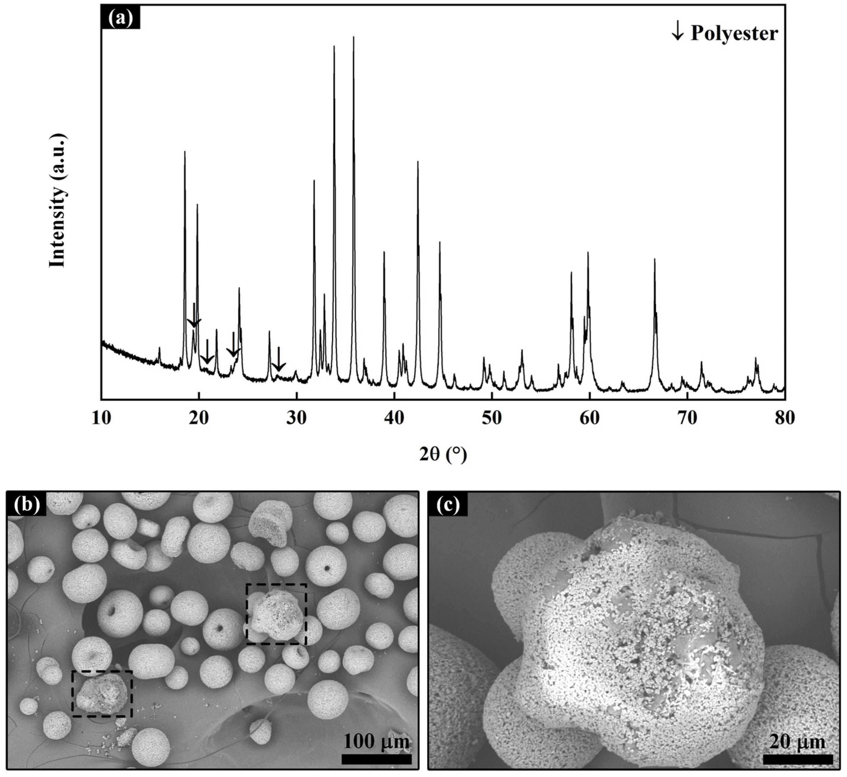
Commercially available Si (99.9%, Shanghai ST-NANO Science and Technology Co., Ltd., Shanghai, China) and YbMS (99.9%, Beijing Sunspraying New Materials Co., Ltd., Beijing, China) powders were employed as the feedstock materials for the Si and YbMS layers. In this study, YbDS and LMA powders were synthesized in-house by a solid-state reaction, and the Si + YbDS mixture powder and the LMA–polyester composite powder were prepared by different methods. For the former, Si and YbDS powders were mixed in a molar ratio of 1:1, followed by the addition of gum arabic, ammonium citrate, and deionized water. After ball-milling together for 36 h, the Si + YbDS mixture powder was obtained by spray-granulating (SFOC-16, Shanghai Ohkawara Dryers Co., Ltd., Shanghai, China). For the latter, the LMA powder was mixed directly with gum arabic, ammonium citrate, and deionized water and ball-milled for 72 h. Finally, the LMA slurry was mechanically stirred with polyester particles (400 mesh, 10 wt.%) for 3 h and then spray-granulated to produce LMA–polyester composite powder. The XRD pattern of LMA–polyester composite powder is shown in Figure 1a, where the arrows refer to the diffraction peaks of crystalline aromatic polyester, while the remaining peaks correspond to those of LMA. Figure 1b shows the SEM images of the LMA–polyester composite powder, with the majority composed of aggregated LMA. However, some particles within the dashed box exhibit partial encapsulation of LMA onto the polyester, which can, to some extent, reduce the loss of polyester during the spraying process, as shown in Figure 1c. In order to determine the actual content and decomposition temperature of polyester, thermogravimetric and differential scanning calorimetry (TG–DSC) analysis of the LMA–polyester composite powder was conducted. As depicted in Figure 2, the DSC curve exhibits two exothermic peaks at 546.5 °C and 582.6 °C, indicating the decomposition of polyester. From the TG curve, it can be observed that the total mass loss corresponding to the two exothermic peaks is 8.1%, which is less than the amount of polyester added. This difference might be attributed to the loss of finer polyester particles carried away by the airflow during the spray-granulating process.

Figure 1.
XRD diffractogram (a) and SEM micrographs (b,c) of LMA–polyester powder.
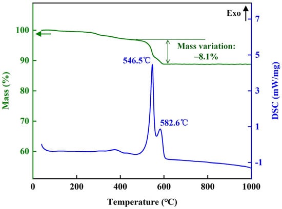
Figure 2.
TG–DSC result of LMA–polyester powder.
2.2. Coating Preparation
The SiC/SiC CMC substrates utilized in this research were supplied by Chongyi Hengyi Ceramic Composites Co., Ltd., Chongyi, China, and fabricated using the precursor infiltration pyrolysis (PIP) process. For sample preparation, the SiC/SiC CMC substrate was cut into dimensions of 30 mm × 15 mm × 4 mm, and the four edges of the front surface were chamfered using a diamond grinding wheel to allow for the over-spray of the coatings on the substrate to reduce edge effects [28]. Following that, the substrate surface was roughed by slight sandblasting with 150 mesh Al2O3 grits under 0.3 MPa. Finally, the substrate was ultrasonically cleaned, soaked in ethanol, and dried before spraying.
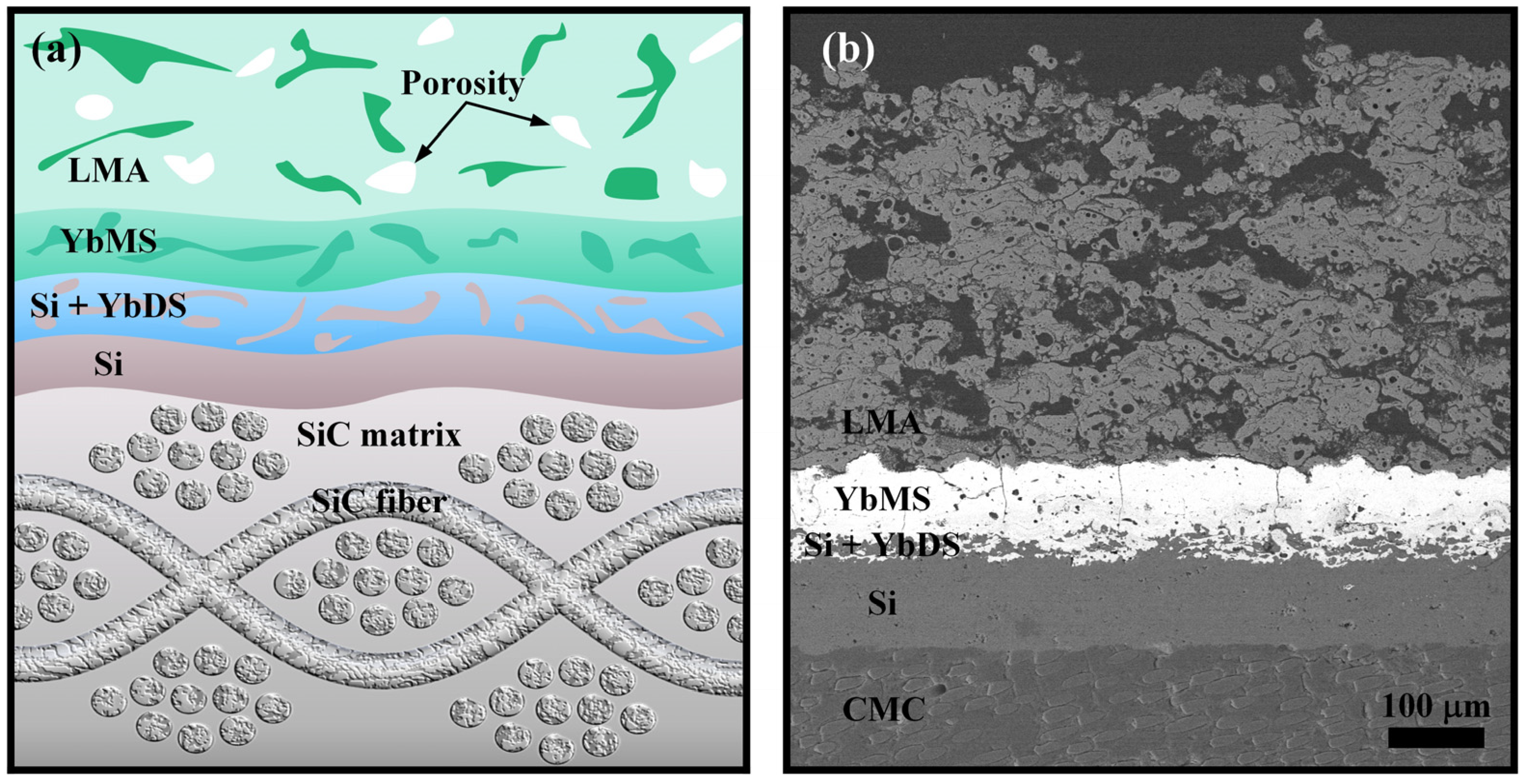
Multilayer Si/Si + YbDS/YbMS EBC was first prepared onto the SiC/SiC CMC substrate using the atmospheric plasma spraying (APS) process (MultiCoat with F4MB-XL, Oerlikon Metco, Wohlen, Switzerland) with a total thickness of 200 μm, during which the uncoated and coated substrate surfaces were preheated (~500 °C) to slow the quenching by plasma flame prior to each coating application. Subsequently, the LMA–polyester composite powder was plasma-sprayed onto the EBC-coated surface to form topcoats with thicknesses of 500 and 1000 μm, respectively, for conducting the thermal shock and isothermal oxidation tests. The sample with a topcoat thickness of 1000 μm was specifically designed to enable simultaneous superficial Rockwell hardness measurement and investigate the effect of prolonged isothermal exposure on the coating hardness. Such measurement typically requires a thicker topcoat to minimize the influence of underlying layers on the results [2]. However, discussions regarding coating hardness are outside the scope of this paper. The coating system used in this study is shown in Figure 3a, and the APS operating parameters are listed in Table 1. According to the recrystallization temperature of the LMA coating reported in our previous work (~900 °C and 1170 °C) [29], all coated samples were subjected to post-spray heat treatment at 1200 °C for 10 h (labeled LMA-0), which can not only recrystallize the coatings but also remove the polyester particles, resulting in the formation of a porous LMA abradable topcoat. Figure 3b shows the SEM image of the LMA-0 sample with a 500-μm-thick LMA topcoat; one can distinguish the dense EBC interlayer beneath the porous LMA topcoat. This topcoat was primarily composed of three distinct components, namely splats, un-melted particles, and pores. The fully melted particles were transformed into relatively dense splats during spraying, the partially melted particles resulted in a loose coating structure, and the large pores within the coating were obtained by the polyester burnout procedure after spraying. In addition, there was a large number of small circular pores within the splats. This was due to the lower spray power, which resulted in a lower particle speed, making it difficult for subsequent molten droplets to expel the entrapped air during deposition [30].
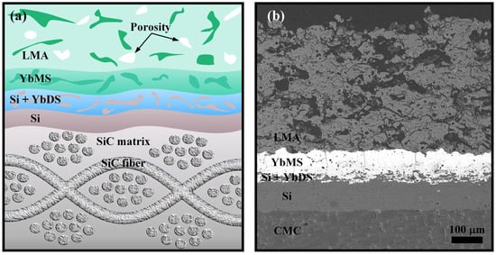
Figure 3.
Schematic diagram (a) and SEM image (b) of the coating structure.

Table 1.
APS operating parameters used in this study.
2.3. Isothermal Oxidation and Thermal Shock Tests
Three samples were prepared and subjected to isothermal oxidation in a muffle furnace (KSL-1700X-S, HF-Kejing, Hefei, China) at 1300 °C under an air atmosphere for durations of 10, 100, and 200 h (labeled as LMA-10, LMA-100, and LMA-200), respectively, with a heating and cooling rate of 5 °C/min. In the thermal shock test, the coated samples were positioned within a specially designed furnace. Each complete thermal shock process lasted for 60 min, involving the fast heating of the coated samples to 1300 °C and maintaining this temperature for 55 min, followed by rapid wind-cooling for 5 min to approximately 150 °C. Three samples were initially thermal-shocked simultaneously, with one removed after 100 shocks, another after 200 shocks, and the last one experiencing overall transverse fracture after 280 shocks, indicating the end of the thermal shock test (labeled as TS-100, TS-200, and TS-280). For high-temperature tests, all coated samples were packed on a platinum crucible to avoid contamination.
2.4. Characterization
The phase compositions of the samples were analyzed through XRD using Cu-Kα radiation in a Rigaku SmartLab instrument. It should be noted that only the LMA topcoat was detected because of the limited penetration depth of X-rays [31]. The microstructure of the samples was examined using SEM (QUANTA FEG 450, Hillsboro, OR, USA) with EDS (Xplore 30, Oxford Instruments, Oxford, UK) for elemental analysis after cold mounting in epoxy resins, sectioning, and fine polishing. Visual inspection and recording were performed using optical microscopy (SZX7, Olympus, Tokyo, Japan). A thermal analyzer (STA449F3 Netzsch, Germany) was used for TG–DSC analysis of the LMA–polyester composite powder from room temperature to 1000 °C, with the heating rate set at 10 °C/min.
3. Results and Discussion
3.1. Isothermal Oxidation
3.1.1. Bubble and Glassy Melt
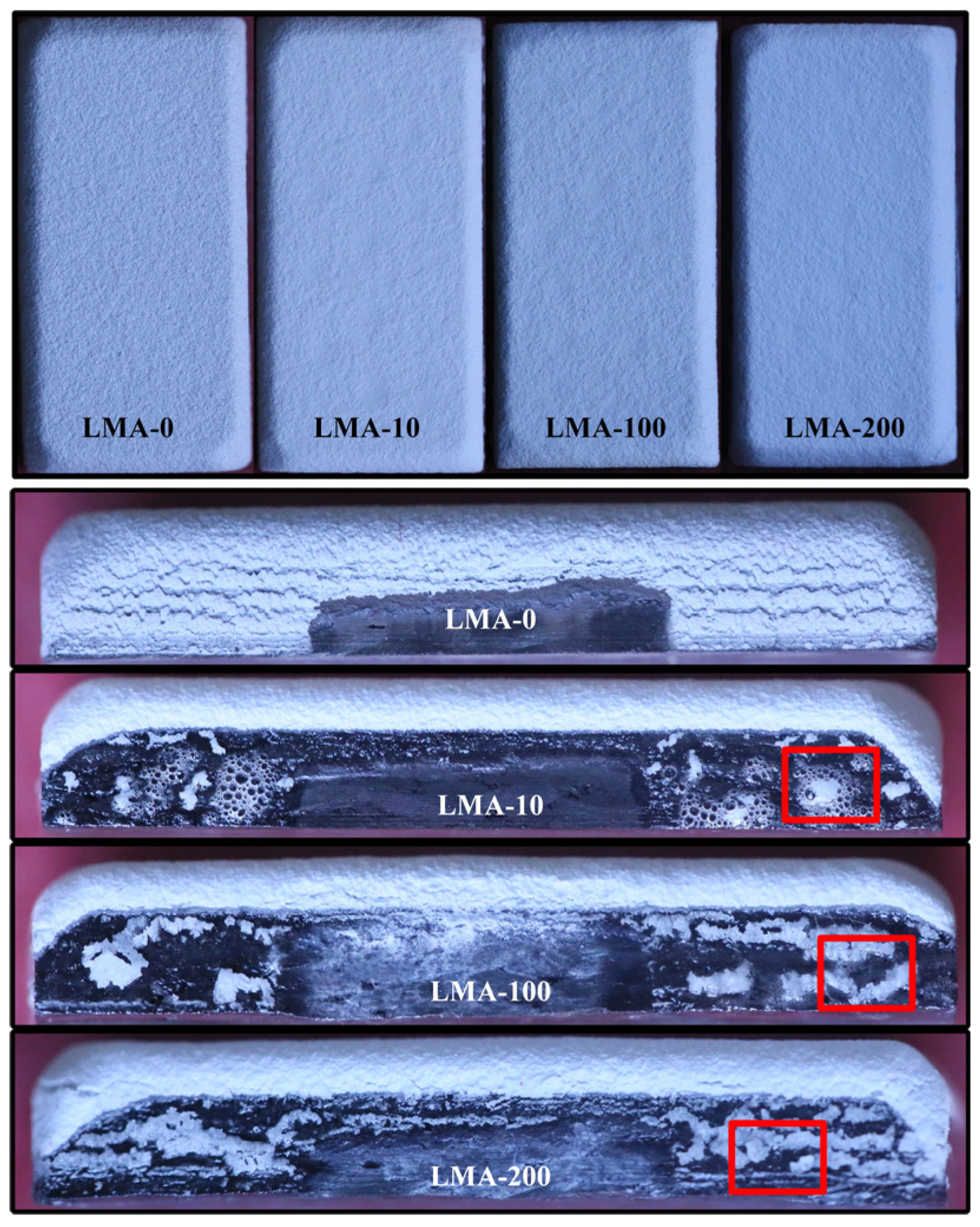
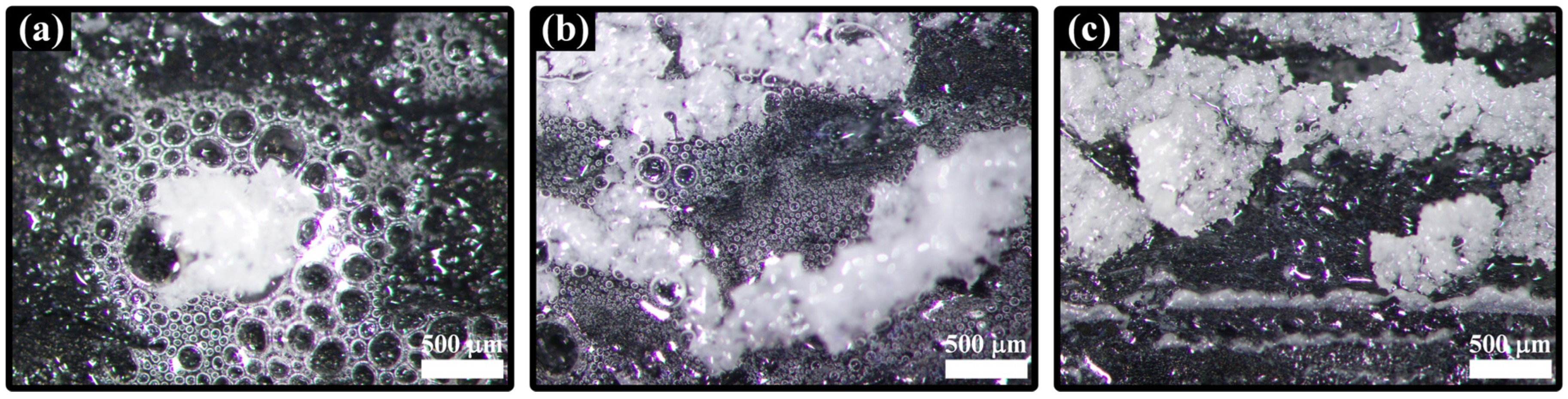
The macroscopic photographs of coated samples after heat treatment at 1200 °C (LMA-0) and isothermal oxidation at 1300 °C (LMA-10, LMA-100, and LMA-200) are shown in Figure 4. No obvious cracking phenomena were observed on the front surfaces of any of the coated samples, but a few horizontal cracks appeared at the chamfered edges, which was caused by stress concentration [26]. Due to the purpose of over-spray in the APS process, one side surface of the coated sample was also slightly covered by the loose coating, which is clearly visible from the side view of the LMA-0 sample, while the other side surface was not covered due to the presence of the fixture used to hold the sample in place during spraying (not shown). For LMA-10, the coverage of the coating significantly decreased, and numerous bubbles appeared in the originally covered areas. For LMA-100 and LMA-200, the bubbles became less pronounced, but the remaining coating increased. It needs to be mentioned that the isothermal oxidation tests for these three samples were conducted separately and not cumulatively, implying that the appearance of bubbles may be related to the decrease in coating coverage after isothermal oxidation, that is, the detachment of the covered coating during the cooling process. To investigate the evolution of bubbles with the isothermal oxidation time, the red solid box regions in Figure 4 were enlarged and recorded using optical microscopy, as shown in Figure 5. It is evident that compared with LMA-10, the bubble size was reduced, but the number increased in LMA-100; however, in LMA-200, there were no clearly observable bubbles. In addition, the entire side surface of all coated samples was filled with glassy melt. In a previous paper [32], it was reported that the formation of bubbles was attributed to the dense microstructure caused by the glassy melt, preventing the outward escape of CO and/or CO2 gases formed by the oxidation of SiC/SiC substrate. As a consequence, with increasing isothermal oxidation time, the temperature-dependent melt viscosity is considered an important factor in the variation in bubble characteristics, as will be detailed below [33,34].
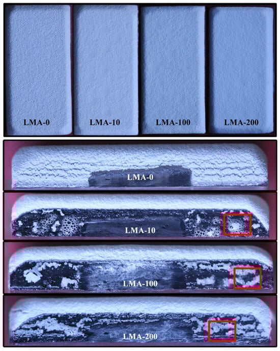
Figure 4.
Macrophotographs of the coated samples under different conditions.
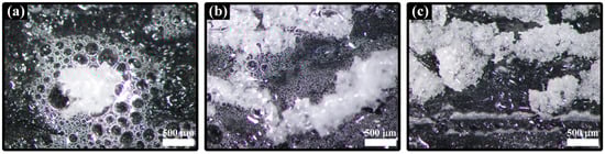
Figure 5.
Enlarged views of the bubble regions: (a) LMA-10; (b) LMA-100; (c) LMA-200.
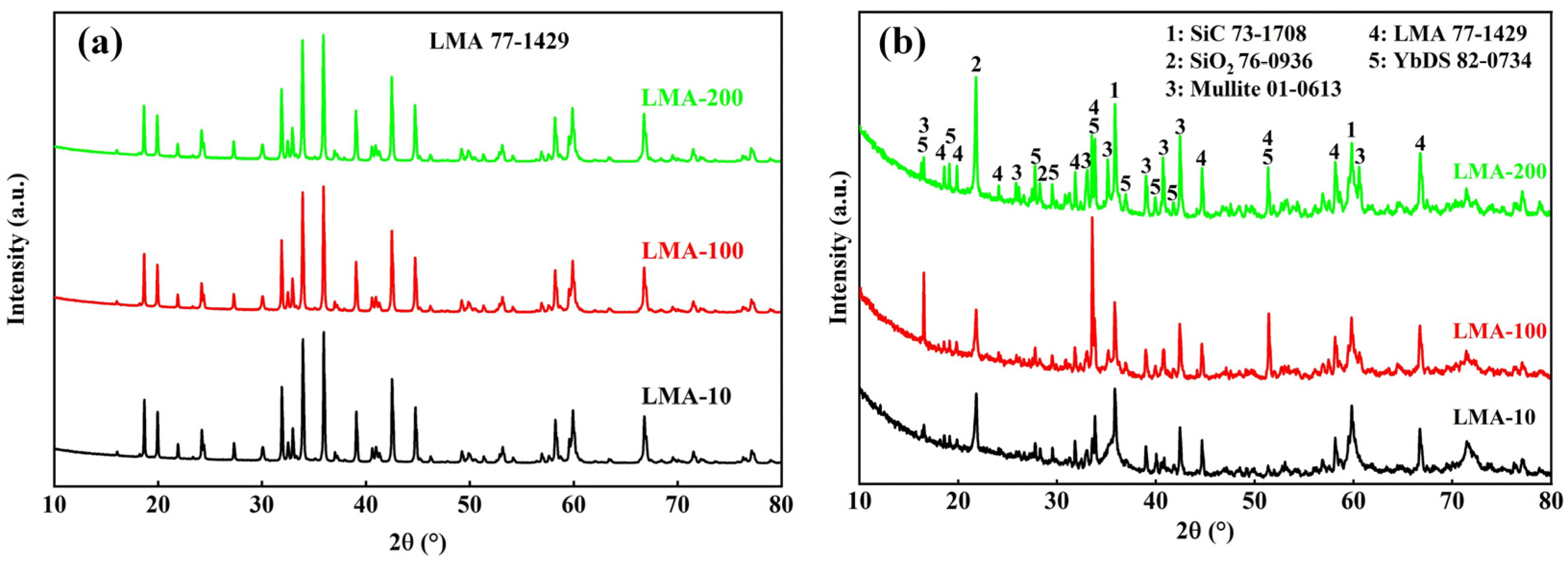
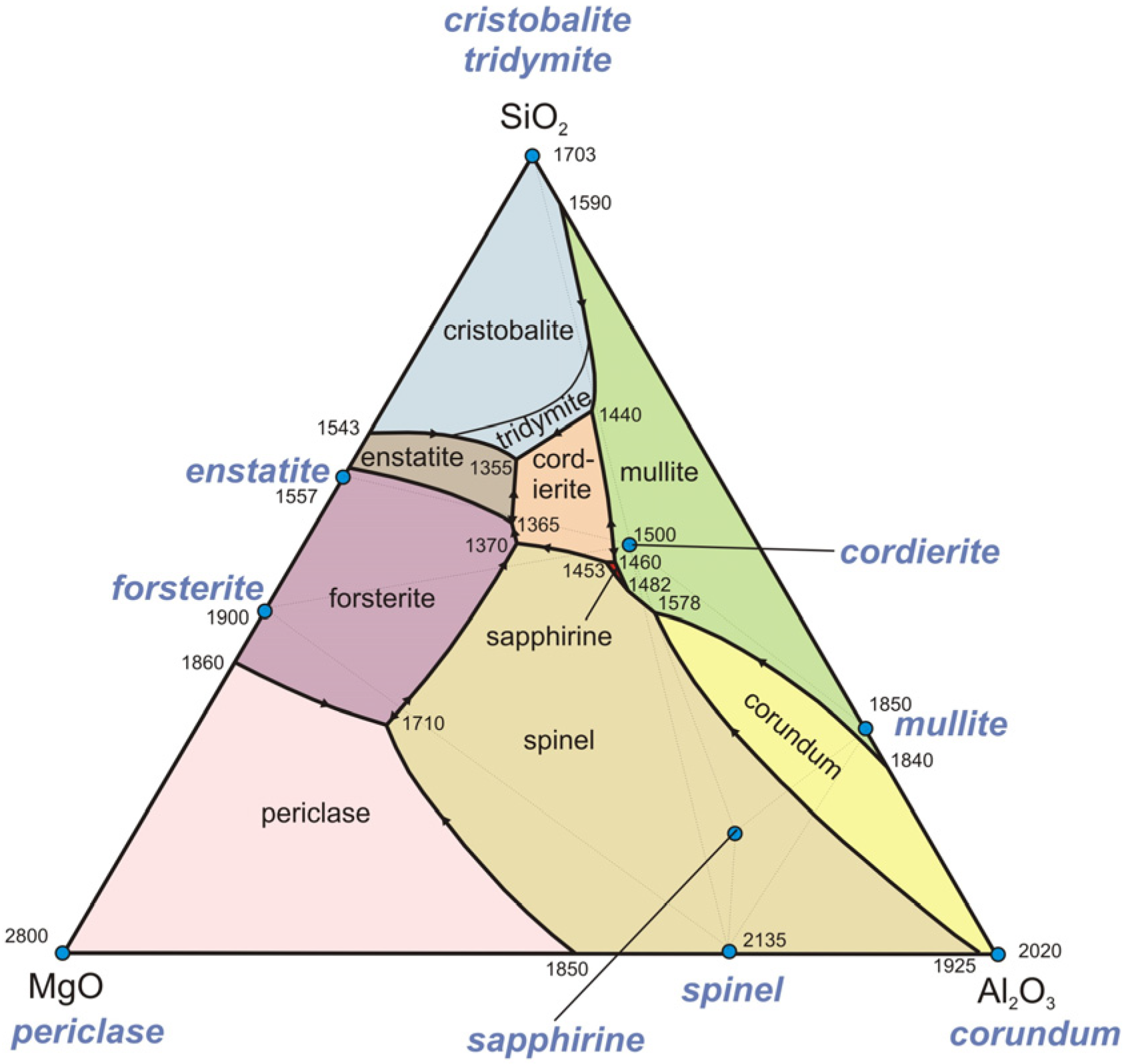
Figure 6 shows the XRD patterns of the front and side surfaces of the coated samples after isothermal oxidation, respectively. From the XRD peaks on the front shown in Figure 6a, the abradable topcoat maintained a single LMA phase during the 200 h isothermal oxidation. From the XRD peaks on the side shown in Figure 6b, it can be observed that in addition to the SiC phase corresponding to the substrate and the LMA and YbDS phases corresponding to the coatings, SiO2 and mullite phases were also present on the side surface of the coated sample, while Si and YbMS phases corresponding to the coatings were not detected. It is speculated that the Si layer covering the side surface and the SiC/SiC substrate oxidized to form SiO2 at elevated temperature, and subsequently, through the reaction between YbMS and SiO2, YbMS was transformed into YbDS [35]. However, the unexpected appearance of mullite is worth noting, as a comparative study conducted by Hu et al. [36] with a completely wrapped coating structure of Si/YbMS/LMA showed that the mullite emerged at an isothermal oxidation temperature of 1360 °C, accompanied by the generation of a glassy mixed layer in the upper layers. It was concluded that enstatite (MgO·SiO2), tridymite (SiO2), and cordierite (2MgO·2Al2O3·5SiO2) formed by the exothermic reaction between YbMS and LMA at above 1300 °C underwent a eutectic reaction at approximately 1355 °C, leading to the appearance of glassy melt and the precipitation of mullite, as shown in the ternary phase diagram in Figure 7 [32]. By contrast, the temperature used in this study was 1300 °C, and similar glassification phenomena only appeared on the side surface covered by the loose coating. Therefore, considering that oxide formation (SiO2) is an exothermic process, this might have generated continuous additional heat during isothermal oxidation, leading to localized temperature rises on the side surface of the coated sample [37]. In general, initial oxidation is the most intense, as the formation of the glassy melt effectively impedes the inward permeation and diffusion of oxygen [36,38]. Therefore, in LMA-10, the relevant temperature rise was the highest, leading to a lower viscosity of the melt and a higher generation of CO and/or CO2 gases, which increased the possibility of bubble formation and coating detachment. As the isothermal oxidation continued (LMA-100 and LMA-200), the slowing oxidation rate of the SiC/SiC substrate resulted in a lower temperature rise and, therefore, an increase in melt viscosity, a decrease in gas generation, and, ultimately, a difference in bubble characteristics.
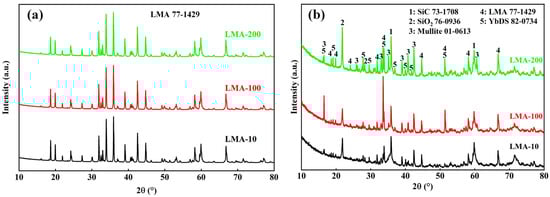
Figure 6.
XRD patterns of the (a) front and (b) side surfaces of the coated samples.
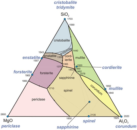
Figure 7.
The Al2O3-MgO-SiO2 ternary phase diagram. Derived from [32,36].
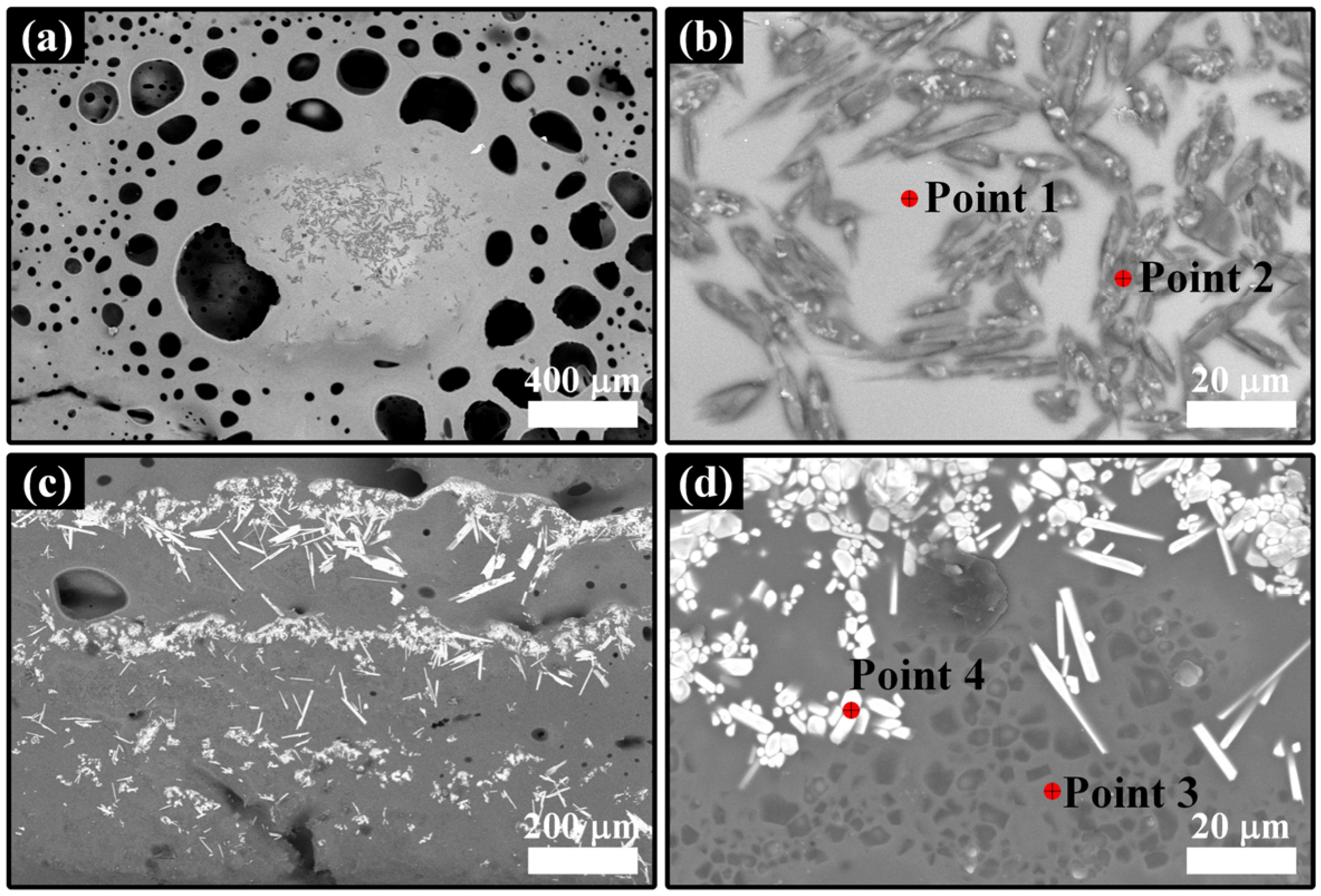
The BSE mode SEM images of the side surface of the coated sample in Figure 5a,c are shown in Figure 8, and the corresponding EDS results are shown in Table 2. For LMA-10, many grey needle-like grains appeared in the glassy melt and were located above the remaining coating dominated by LMA (Figure 8a,b). Furthermore, according to the Al/Si atomic ratio at point 2, the phase composition of these grains was close to that of the mullite (Al6Si2O13). As shown in Figure 8c,d, needle-like grains also appeared in the melt regions without any remaining coating in LMA-200, but they exhibited a white contrast. EDS quantitative analysis at point 4 indicated that the white needle-like grains had an approximate atomic ratio of Yb and Si, suggesting that they were YbDS. The findings of the above analyses are consistent with the XRD results in Figure 6b, involving the dissolution of YbMS and partial LMA into melt (points 1 and 3 in Figure 8) and the precipitation of crystalline YbDS and mullite phases [39,40].
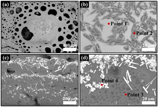
Figure 8.
SEM images of the side surface of the coated sample: (a,b) LMA-10, (c,d) LMA-200; (b,d) are high-magnification views in the (a,c) regions, respectively.
Table 2.
EDS point scan results in Figure 8.
3.1.2. Coating Microstructure
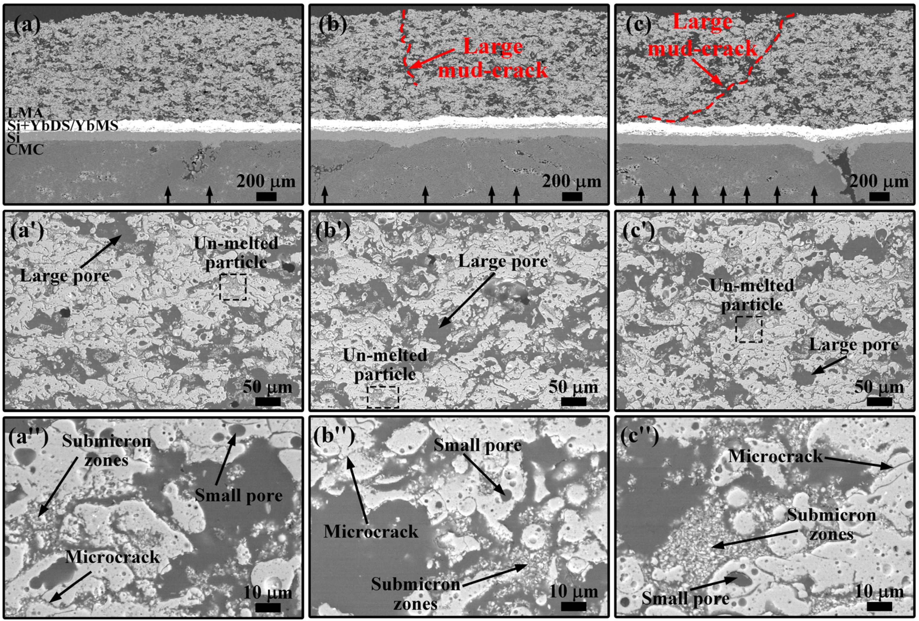
Figure 9 shows the BSE–SEM images of the LMA-10, LMA-100, and LMA-200 samples. For LMA-10, the interfaces between the coatings and the substrate were well combined, but a few vertical cracks (mud cracks) were observed in the YbMS interlayer, as indicated by the black arrows in Figure 9a. These cracks may have resulted from the thermal mismatch stresses generated during the spraying process and the cooling stage of the heat treatment, along with the volume shrinkage associated with recrystallization [41]. For LMA-100 and LMA-200, as shown in Figure 9b,c, large mud cracks (red dashed lines) appeared in the porous LMA topcoat, and the depth of crack propagation increased with the prolonged isothermal oxidation time. At the same time, the number of mud cracks in the interlayer increased (black arrows). It is worth noting that the large mud crack in LMA-200 extended inward gradually along a direction parallel to the coating surface and terminated at the YbMS/LMA interface instead of the common mode perpendicular to the coating surface. On the one hand, cracks tend to propagate along the path of the least resistance (porosity); on the other hand, this is related to the excellent mechanical properties of YbMS itself, which has higher stress tolerance [42,43]. This crack deflection acts as a toughening mechanism to reduce the risk of damage to the interlayer from thick topcoats with higher stress levels [26,44]. Compared with heat treatment at 1200 °C, the microstructure of the porous LMA topcoat remained almost unchanged after isothermal oxidation at 1300 °C, as shown in Figure 9a′–c″. The size of these unmelted particles has not significantly increased, maintaining a submicron size and indicating an excellent resistance to sintering.
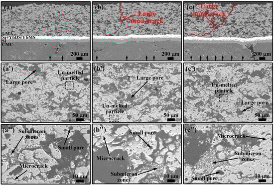
Figure 9.
SEM cross-section micrographs of the coated samples: (a–a″) LMA-10; (b–b″) LMA-100; (c–c″) LMA-200.
In order to investigate the isothermal oxidation behaviors of the Si/Si + YbDS/YbMS interlayers, the coating interfaces were characterized by high-magnification SEM micrographs, as shown in Figure 10a–c. After the prolonged isothermal oxidation, there was no significant increase in the opening displacement or propagation of the mud cracks in the YbMS layer, and the cracks terminated within the YbMS layer and did not propagate further into the Si + YbDS layer. This is mainly attributed to the relatively good thermal expansion matching between the underlayers [26]. In addition, due to the lower CTE of Si than that of SiC/SiC substrate, the compression in the Si regions can prevent the cracks from extending downward.
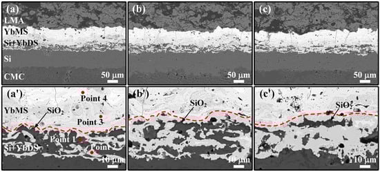
Figure 10.
Cross-sectional SEM micrographs of the interlayers of the coated samples: (a,a′) LMA-10; (b,b′) LMA-100; (c,c′) LMA-200.
The SEM image of the interface between the Si + YbDS layer and the YbMS layer after 10 h of isothermal oxidation is shown in Figure 10a′. It can be clearly observed that four different contrasts are included, and these contrasts were quantitatively analyzed by EDS, as shown in Table 3. The black contrast (point 1) contained only Si and O elements, indicating that the Si constituent was subjected to slight oxidation during spraying, heat treatment, and isothermal oxidation; the contents of Yb and Si elements in the dark grey contrast (point 2) were relatively close, suggesting that it was YbDS; the content of Si element in the light grey contrast (point 3) was about half that of Yb element, indicating that it was YbMS; the white contrast (point 4) showed a lower Si content (5.3 at%), indicating that it was Yb2O3, possibly resulting from the decomposition of YbMS during spraying. With increasing isothermal oxidation time, as depicted in Figure 10b′,c′, the area representing YbDS in the dark grey contrast of the Si + YbDS layer increased; meanwhile, the areas representing Si in black contrast and YbMS in light grey contrast decreased. The above phenomena involved the continuous oxidation of the Si constituent during isothermal oxidation and the subsequent reaction of SiO2 with YbMS [27]:
Si + O2 +Yb2SiO5 → Yb2Si2O7
Table 3.
EDS point scan results in Figure 10.
This has a beneficial effect of consuming SiO2, which is detrimental to the thermal shock resistance of the coatings. As reported in the literature, a reversible phase transformation between β- and α-cristobalite during thermal shock, along with significant volume change, led to severe microcracking of the SiO2 scale known as thermally grown oxide (TGO), [45,46]. These microcracks establish a rapid diffusion pathway for oxidants, facilitating their reach to the un-oxidized Si constituent and consequently increasing the oxidation rate. The consumption of YbMS, generated by the decomposition of YbDS during spraying, also benefits the coating lifetime by reducing thermal mismatch stress. In addition, the in situ-formed YbDS constituent exhibits dense microstructures without any defects, which is expected to effectively reduce the oxidation of the underlying Si bond coat. However, a little SiO2 TGO formation was observed on the side of the Si constituent near the Si + YbDS/YbMS interface. To address this issue, further studies are needed that more finely adjust the ratio and distribution of the Si and YbDS constituents.
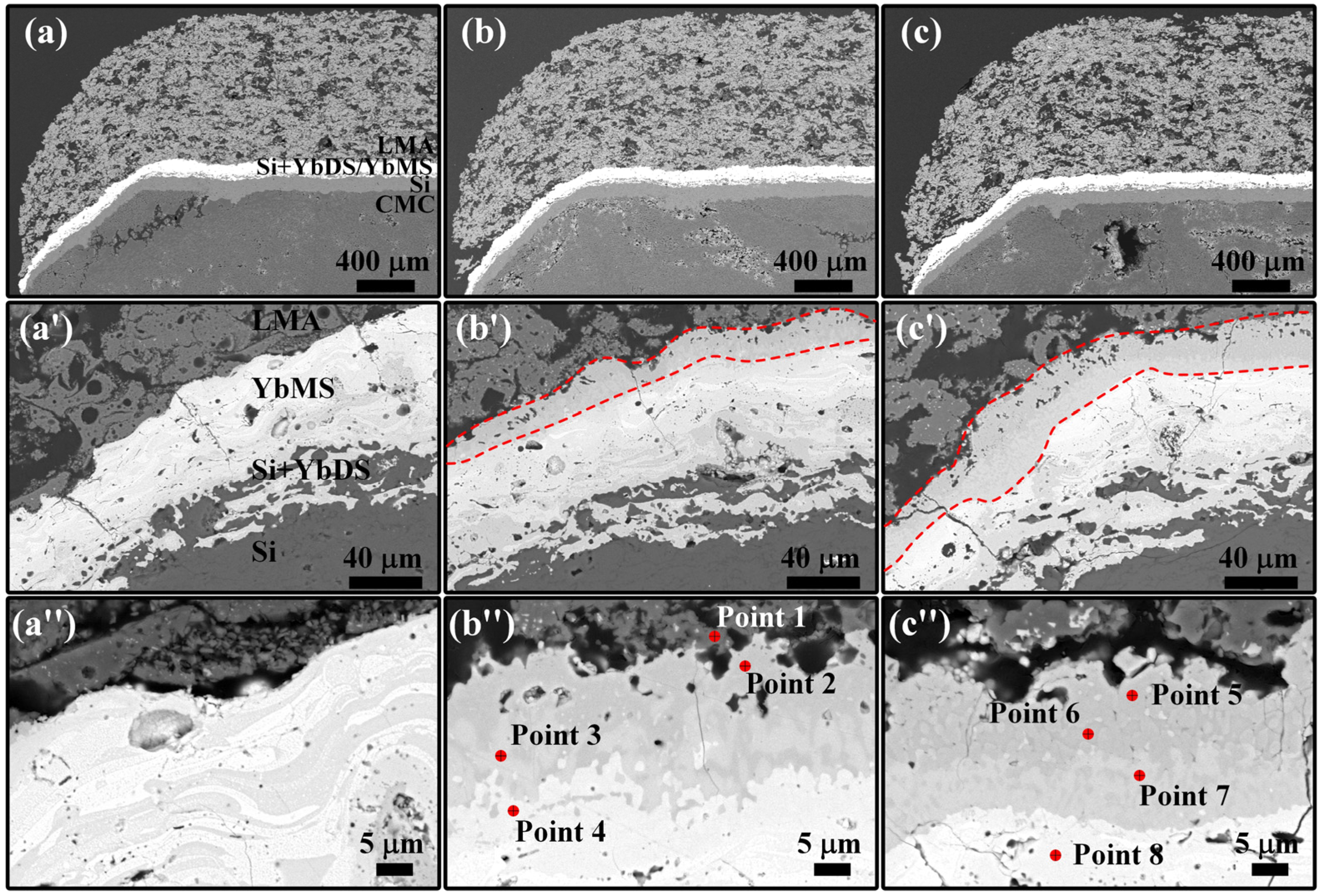
Figure 11a–c show the low-magnification SEM images at the edge of the coated samples. The edges of the thick LMA topcoat (~1 mm) remained intact after prolonged isothermal oxidation without any large cracking or delamination, which was attributed to the excellent resistance to the sintering of the LMA material at 1300 °C, and at the same time, the larger porosity contributed to stress relaxation. An interesting phenomenon was observed at the chamfer where the coating thickness decreased. However, even at the very edge, the LMA topcoat retained a thickness of several hundred micrometers. This suggests that the coating covering the side surface was dominated by LMA, and mullite may be the main reaction product. However, the absence of prominent mullite peaks in the XRD pattern of Figure 6b demonstrates that it may have dissolved in the glassy melt (points 1 and 3 in Figure 8). The SEM images at the chamfer are shown in Figure 11a′–c′. Similar to Figure 10, the YbDS constituent in the Si + YbDS layer increased, while the Si constituent decreased with the increase in isothermal oxidation time. The difference is that a distinct reaction layer appeared between the YbMS/LMA interface after 100 h of isothermal oxidation, and the thickness increased after 200 h. Interestingly, the thick reaction layer only appeared at the chamfered edge with glassy melt on one side surface of the sample, and the corresponding interface on the other side surface was relatively stable. Generally, at 1300 °C, LMA reacts slightly with YbMS to form a thin interface layer dominated by Yb3Al5O12 [32,47]. This suggests that the Al-rich melt and mullite products on the side surface of the sample may be responsible for the prominent reaction layer.
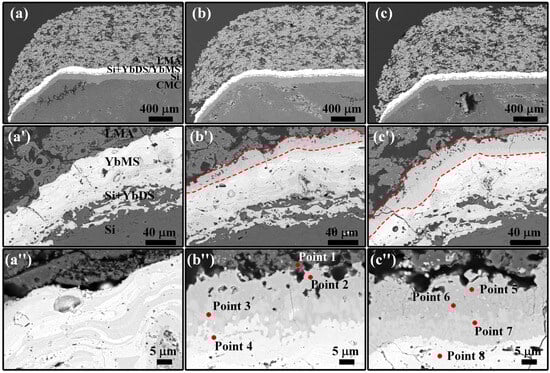
Figure 11.
SEM cross-section micrographs at the edge of the coated samples: (a–a″) LMA-10; (b–b″) LMA-100; (c–c″) LMA-200.
Therefore, EDS point analysis was performed in the high-magnification micrographs of the reaction layer, as shown in Figure 11a″–c″ and Table 4. After 100 h of isothermal oxidation, it was observed from points 1 and 4 that these two layers were LMA and YbMS, respectively, with nearly stoichiometric ratios. In the reaction layer near LMA (point 2), Yb, Si, Mg, and Al elements were present. Since there is no corresponding single phase for these four elements, it is identified as containing at least two phases. The Si and Mg contents were similar, and the Yb/Al ratio was close to 3:5, so the possible phase compositions were MgSiO3 and Yb3Al5O12. In the reaction layer near YbMS (point 3), Yb, Si, and La elements were present with similar contents. Yb and La are both rare earth elements, suggesting a possible phase composition of a LaXYb2-XSiO5 solid solution. After 200 h of isothermal oxidation, it is observed from point 8 that the reaction front moved toward the YbMS side, and the thickness of the reaction layer near the LMA side increased. In the reaction layer near YbMS (point 7), only Yb and Si elements were present with similar contents, suggesting a possible phase composition of YbDS. In the reaction layer near LMA, two distinct contrasts were observed. The shallower contrast region (point 5) had elements and contents similar to point 2, possibly indicating MgSiO3 and Yb3Al5O12. The deeper contrast region (point 6) had a lower Yb content compared with point 3, suggesting a possible phase composition of LaXYb2-XSi2O7. These evolutions indicate that as the isothermal oxidation proceeded, the original LaXYb2-XSiO5 solid solution (point 3) and YbMS (point 4) continuously lost Yb ions, which subsequently diffused toward the LMA side to form the dominant Yb3Al5O12. The glassy melt containing a large number of Al ions accelerated the elemental diffusion and the consequent interfacial reaction, which could explain the movement of the reaction front. Ultimately, this resulted in the phase transformation of LaXYb2-XSiO5 and YbMS into LaXYb2-XSi2O7 and YbDS, respectively. This phenomenon parallels the behavior observed when Yb2O3-rich coatings encounter calcium–magnesium–alumina–silicate (CMAS) deposits at elevated temperatures, which involves the dissolution of YbMS and, upon saturation, the subsequent precipitation of Yb3Al5O12 garnet [39,48]. In addition, due to the closely matched CTE between YbMS (7.5 × 10⁻⁶ K−1) and Yb3Al5O12 (7.83 × 10⁻⁶ K−1), no cracks were observed in the reaction layer [45,49]. However, porosity increased in the reaction layer near the LMA, as shown in Figure 11b′,c′.
Table 4.
EDS point scan results in Figure 11.
According to the above analysis, a comprehensive description of the corrosion behavior can be provided. The microstructure evolution on the side surface of the coated sample during isothermal oxidation at 1300 °C is shown in Figure 12. In short-term oxidation (1300 °C × 10 h), the higher local temperature rise caused by the greater oxidation rate of the SiC/SiC substrate results in the formation of melt with lower viscosity. This hinders the escape of CO and/or CO2 gases, leading to the formation of larger bubbles and the detachment of a significant portion of the coatings covered. Simultaneously, some coatings are retained because they are enveloped by the melt. As the oxidation time increases (1300 °C × 100 h and 200 h), the dense microstructure formed by the melt prevents the inward penetration of oxygen, reducing the oxidation rate of the substrate. This gradual decrease in local temperature rise, coupled with the increased viscosity of the melt, slows the formation of bubbles. Consequently, more coatings are retained. During this period, the melt rich in Al comes into contact with the YbMS/LMA interface, accelerating their reaction and exacerbating the degradation of YbMS. Although the impact of this reaction layer on the performance of the coatings requires further research, the melt indeed has the capability to protect the integrity of the substrate, as reported in our previous studies, preventing a significant reduction in strength retention [36].
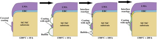
Figure 12.
Schematic diagram of microstructure evolution.
3.2. Thermal Shock
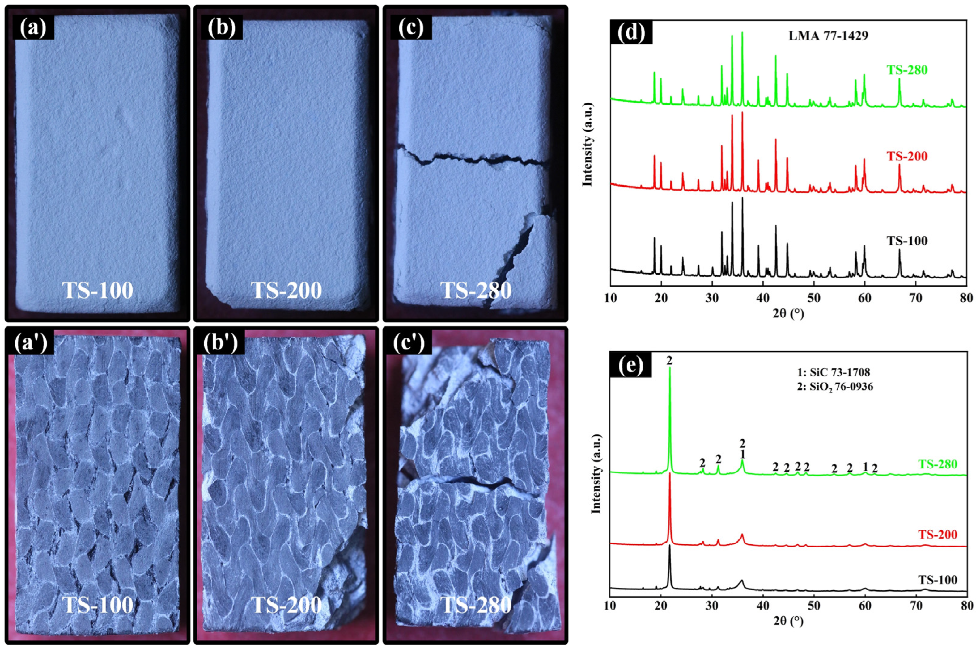
The macroscopic photographs on the front and back of the coated samples after 100, 200, and 280 shocks (TS-100, TS-200, and TS-280) are shown in Figure 13a–c′, with no coating protection on the back due to single-sided spraying. After 100 shocks, the front coating was intact, while the backside substrate exhibited slight oxidation. Following 200 shocks, there was coating damage at one corner on the front side due to a partial fracture of the SiC/SiC substrate on the backside. After 280 shocks, the samples exhibited overall transverse fracture with significant substrate contraction, but the coating still adhered well. Additionally, it is evident that severe oxidation occurred inside the SiC/SiC substrate after the fracture. Figure 13d shows the XRD pattern of the front surface of the coated samples, revealing the stability of the LMA coating during the thermal shock test, with no observable phase transition. However, as depicted in Figure 13e, diffraction peaks associated with the SiO2 phase appeared in the XRD pattern on the backside, and the intensity of these peaks increased with the increase in the number of shocks. This not only indicates the poor durability of SiC/SiC substrate without coating protection at the high temperature of 1300 °C but also highlights the excellent thermal shock resistance exhibited by the coatings.
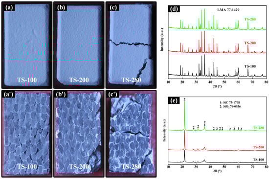
Figure 13.
Front and back images of TS-100 (a,a′), TS-200 (b,b′), and TS-280 (c,c′); (d,e) show the XRD patterns, respectively.
The microstructure in the middle of the coated samples was analyzed through low-magnification SEM images, as shown in Figure 14a–c. After the thermal shocks, there was good bonding between the coatings and substrate, and no apparent large mud crack was observed in the porous LMA topcoat. Remarkably, even in coated samples subjected to 280 shocks resulting in overall transverse fracture, no delamination of the coatings was observed. Similar to the observations in the coated samples after isothermal oxidation, mud cracks were observed in the YbMS interlayer after thermal shocks, and the number increased with continued shocking, as indicated by the black arrows. Figure 14a′–c′ show the high-magnification SEM images of the Si/Si + YbDS/YbMS interlayers. The most significant variation was the increasing opening displacement of the mud cracks with thermal shocks, reaching approximately 5 μm in the coated sample of TS-280. This is a result of the gradual accumulation and release of thermal mismatch stresses within the coatings. Generally, the main concern with mud cracks lies in providing a rapid pathway for oxygen diffusion, leading to the oxidation of the internal Si layer and potentially affecting the lifespan of the coatings. However, it can be observed that even as the cracks widen, they do not extend into the Si layer or even the SiC/SiC substrate. The Si + YbDS mixture layer functions by applying compressive stress and consuming SiO2 and YbMS through reactions, inhibiting the continuous propagation of mud cracks and reducing the likelihood of subsequent microcracking of the SiO2 scale.
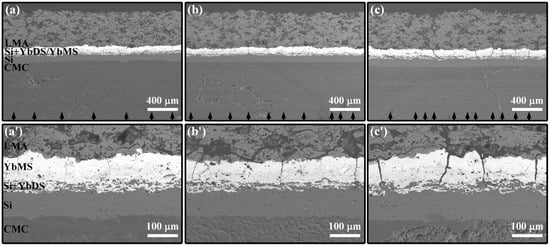
Figure 14.
SEM cross-section micrographs at the middle of TS-100 (a,a′), TS-200 (b,b′), and TS-280 (c,c′).
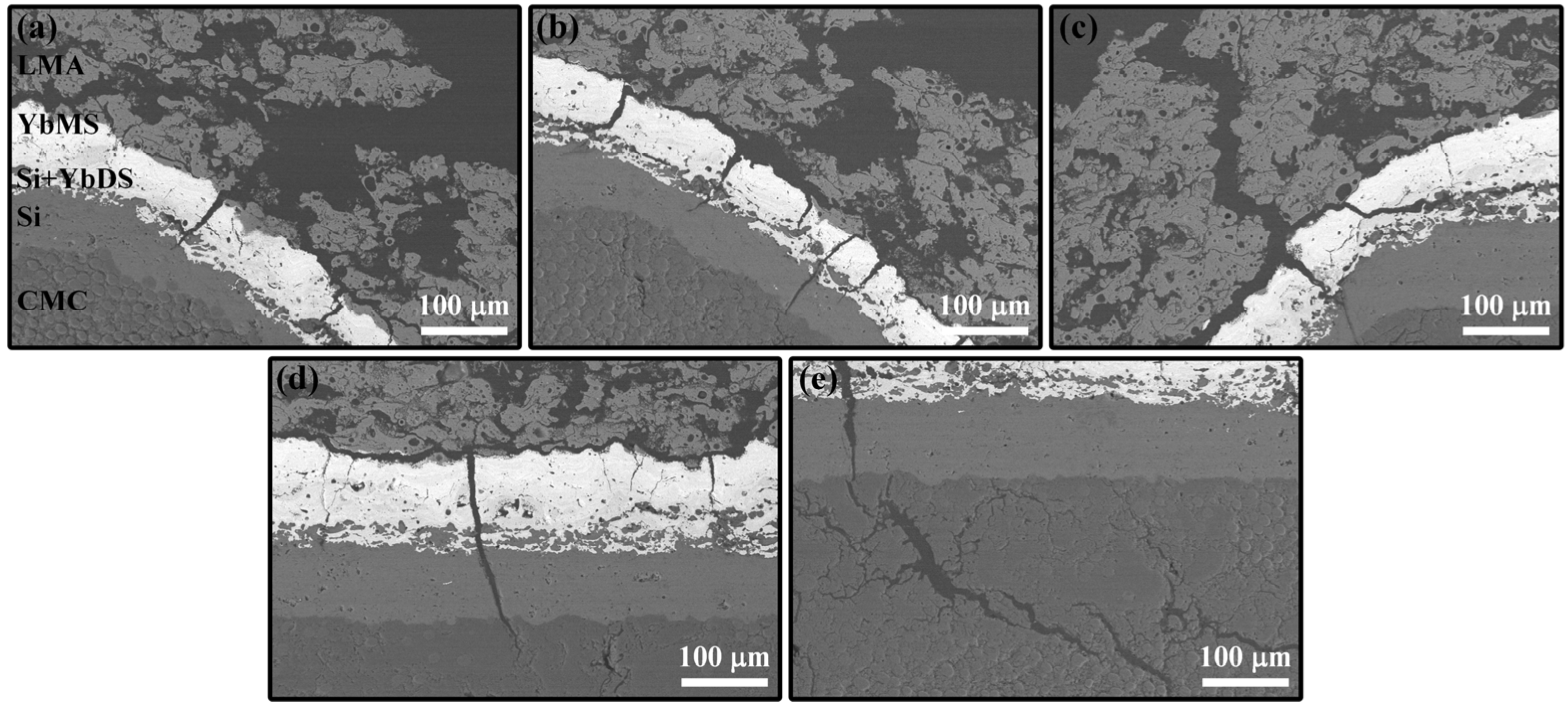
Figure 15 shows the cross-sectional SEM images of the TS-100, TS-200, and TS-280 samples near both edges, where the damage to the coatings and substrate was more severe. For TS-200, a large mud crack emerged at the chamfered edge of the LMA topcoat (region 1), and a mud crack originating from YbMS directly propagated into the SiC/SiC substrate (region 4). For TS-280, cracks occurred in the LMA topcoat at both chamfered edges, with an increased displacement in the crack opening (regions 2 and 3). More surprisingly, a crack network formed within the SiC/SiC substrate, which could be one of the reasons for the substrate fracture (region 5). To investigate the crack propagation, the five regions above were characterized by high-magnification SEM images, as shown in Figure 16. The extent of cracking in regions 1 and 2 of the LMA topcoat was similar, but there was an increase in the number of mud cracks in the interlayer with thermal shocks. Region 3 exhibited a distinctive cracking pattern, where a large mud crack originating in the LMA topcoat bifurcated after extending to the YbMS/LMA interface, as shown in Figure 16c. One branch extended along the interface; another continued inward and terminated within the Si + YbDS mixture layer; and the third penetrated the entire coating structure, reaching the interior of the SiC/SiC substrate. In general, the higher stress concentration at the chamfered edge is a result of the combined in-plane tension and bending moment exerted by the overlying coatings [26]. This results in the crack extending vertically until it encounters a defect or compression region, at which point bifurcation occurs. However, the extension of cracks along the YbMS/LMA interface may be attributed to weaker interface bonding due to the lower power and longer distance when spraying the LMA topcoat. The mud crack in region 4 was also connected to a horizontal crack along the YbMS/LMA interface, Figure 16d, which is expected to be detrimental to the thermal shock resistance of the topcoat. Furthermore, more severe substrate damage occurred beneath the mud crack in region 5 of the TS-280 sample, as shown in Figure 16e. Specifically, the through-coating crack acts as a shortcut for the in-diffusion of oxygen to directly contact the substrate, leading to severe oxidation of the substrate at high temperatures. During the thermal shock process, due to the volume change caused by the phase transformation of SiO2 TGO, the substrate undergoes cracking, forming a network of cracks and ultimately contributing to the fracture of the substrate.
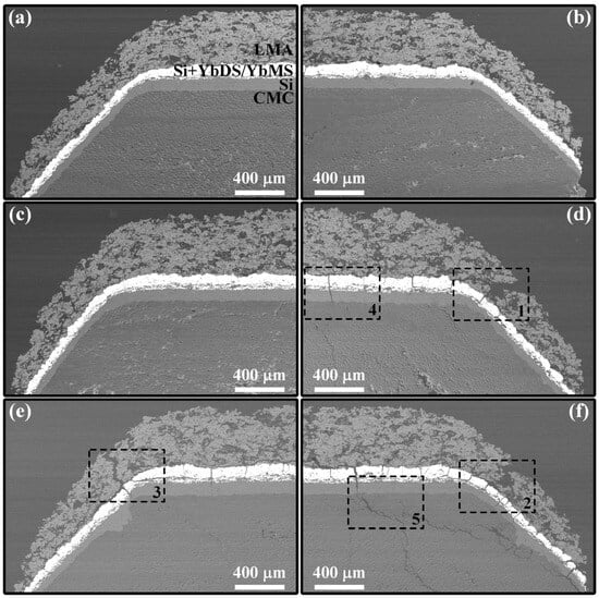
Figure 15.
SEM cross-section micrographs at both edges of TS-100 (a,b), TS-200 (c,d) and TS-280 (e,f).

Figure 16.
SEM cross-section micrographs of the cracking zone at both edges of the coated samples after thermal shock test: (a) zone 1; (b) zone 2; (c) zone 3; (d) zone 4; (e) zone 5.
4. Conclusions
An abradable topcoat based on LMA was prepared by APS onto SiC/SiC CMCs through an EBC interlayer with a coating system of Si/Si + YbDS/YbMS, featuring loose coatings covered on the side surface of the sample due to over-spray. Isothermal oxidation behavior and thermal shock resistance were investigated at 1300 °C, and some significant phenomena through studying the phase composition and microstructure of the samples were obtained, as follows:
- The additional heat generated by the oxidation of the SiC/SiC substrate led to a localized temperature rise on the side surface of the coated sample. This in turn resulted in the formation of glassy melt through a eutectic reaction, further contributing to bubble formation due to its dense nature. The promotion of element diffusion by the melt led to an acceleration of the interfacial reaction between the YbMS and LMA layers at the chamfered edge, with the reaction front extending toward the YbMS side.
- During the initial stage of oxidation, a higher temperature rise and a lower melt viscosity occurred, resulting in the generation of numerous bubbles and the detachment of coatings covered. Subsequently, as the melt acted as a barrier to oxygen in-diffusion, there was a subsequent decrease in the temperature rise, an increase in melt viscosity, and, ultimately, the disappearance of bubbles.
- In the thermal shock test, the lack of coating protection on the backside of the sample resulted in continuous oxidation and cracking damage to the SiC/SiC substrate, ultimately leading to an overall transverse fracture. While the coated side did not experience coating delamination, the mud cracks contributed to the formation of a crack network within the substrate.
Author Contributions
Conceptualization, J.H. and X.C.; methodology, L.D. and J.J.; software, X.L.; formal analysis, S.D. and L.L.; investigation, M.X. and G.L.; resources, J.H. and W.C.; data curation, J.H. and M.C.; writing—original draft preparation, J.H.; writing—review and editing, X.C.; supervision, M.C.; project administration, X.C.; funding acquisition, X.C. All authors have read and agreed to the published version of the manuscript.
Funding
This work was financially supported by the National Natural Science Foundation of China (grant numbers U2241238, 52275461, 92060201), the Major Program (JD) of Hubei Province (grant number 2023BAA003), and the Key Research and Development Program of Hubei Province (grant number 2023BAB107).
Institutional Review Board Statement
Not applicable.
Informed Consent Statement
Not applicable.
Data Availability Statement
Datasets are available from the corresponding author upon reasonable request.
Conflicts of Interest
The authors declare no conflicts of interest.
References
- Sporer, D.; Wilson, S.; Giovannetti, I.; Refke, A.; Giannozzi, M. On The Potential Of Metal And Ceramic Based Abradables. In Tur-Bine Seal Applications, Proceedings of the Thirty-Sixth Turbomachinery Symposium, Houston, TX, USA, 10–13 September 2007; Texas A&M University, Turbomachinery Laboratories: Dallas, TX, USA, 2007; pp. 79–86. [Google Scholar]
- Dorfman, M.R.; Fiala, P.; Hajmrle, K.; Wilson, S. Future Abradable Requirements Needed by Aerospace OEM’s and Their Material and Equipment Suppliers. In Proceedings of the ASME Turbo Expo, Montreal, QC, Canada, 14–17 May 2007; pp. 17–24. [Google Scholar]
- Novinski, E.R. The Selection and Performance of Thermal Sprayed Abradable Seal Coatings for Gas Turbine Engines. In Proceedings of the Annual Aerospace/Airline Plating and Metal Finishing Forum and Exposition, New Orleans, LA, USA, 27–30 March 1989; pp. 60–63. [Google Scholar]
- Sporer, D.; Wilson, S.; Dorfman, M. Ceramics for Abradable Shroud Seal Applications. Ceram. Eng. Sci. Proc. 2009, 4, 39–54. [Google Scholar]
- Cao, X.Q.; Vassen, R.; Stoever, D. Ceramic materials for thermal barrier coatings. J. Eur. Ceram. Soc. 2004, 24, 1–10. [Google Scholar] [CrossRef]
- Lashmi, P.; Ananthapadmanabhan, P.; Unnikrishnan, G.; Aruna, S. Present status and future prospects of plasma sprayed multilayered thermal barrier coating systems. J. Eur. Ceram. Soc. 2020, 40, 2731–2745. [Google Scholar] [CrossRef]
- Luo, L.; Chen, Y.; Zhou, M.; Shan, X.; Lu, J.; Zhao, X. Progress update on extending the durability of air plasma sprayed thermal barrier coatings. Ceram. Int. 2022, 48, 18021–18034. [Google Scholar] [CrossRef]
- Vaßen, R.; Bakan, E.; Mack, D.E.; Guillon, O. A Perspective on Thermally Sprayed Thermal Barrier Coatings: Current Status and Trends. J. Therm. Spray Technol. 2022, 31, 685–698. [Google Scholar] [CrossRef]
- Vassen, R.; Stuke, A.; Stöver, D. Recent Developments in the Field of Thermal Barrier Coatings. J. Therm. Spray Technol. 2009, 18, 181–186. [Google Scholar] [CrossRef]
- Aussavy, D.; Bolot, R.; Montavon, G.; Peyraut, F.; Szyndelman, G.; Gurt-Santanach, J.; Selezneff, S. YSZ-Polyester Abradable Coatings Manufactured by APS. J. Therm. Spray Technol. 2015, 25, 252–263. [Google Scholar] [CrossRef]
- Cheng, T.; Wang, Z.; Dai, S.; Wang, S. Fabrication of ceramic sealing coatings for shell bionic structures and their failure mecha-nism during thermal cycling. Ceram. Int. 2023, 49, 8962–8975. [Google Scholar] [CrossRef]
- Sporer, D.R.; Taeck, U.; Dorfman, M.R.; Nicoll, A.R.; Giannozzi, M.; Giovannetti, I. Novel Ceramic Abradable Coatings with En-hanced Performance. In Proceedings of the ASME Turbo Expo 2006: Power for Land, Sea, and Air, Barcelona, Spain, 8–11 May 2006; pp. 1017–1023. [Google Scholar]
- Lima, R.S.; Marple, B.R. Thermal Spray Coatings Engineered from Nanostructured Ceramic Agglomerated Powders for Struc-tural, Thermal Barrier and Biomedical Applications: A Review. J. Therm. Spray Technol. 2007, 16, 40–63. [Google Scholar] [CrossRef]
- Ali, R.; Huang, T.; Song, P.; Zhang, D.; Ali, S.; Arif, M.; Awais, S.; Hanifi, D.; Lu, J. Tribological performance and phase transition of MAX-phase/YSZ abradable seal coating produced by air plasma spraying. Ceram. Int. 2022, 48, 4188–4199. [Google Scholar] [CrossRef]
- Tejero-Martin, D.; Bennett, C.; Hussain, T. A review on environmental barrier coatings: History, current state of the art and future developments. J. Eur. Ceram. Soc. 2020, 41, 1747–1768. [Google Scholar] [CrossRef]
- Lee, K.N.; Zhu, D.; Lima, R.S. Perspectives on Environmental Barrier Coatings (EBCs) Manufactured via Air Plasma Spray (APS) on Ceramic Matrix Composites (CMCs): A Tutorial Paper. J. Therm. Spray Technol. 2021, 30, 40–58. [Google Scholar] [CrossRef]
- Xu, Y.; Hu, X.; Xu, F.; Li, K. Rare earth silicate environmental barrier coatings: Present status and prospective. Ceram. Int. 2017, 43, 5847–5855. [Google Scholar] [CrossRef]
- Qin, D.; Niu, Y.; Li, H.; Zhong, X.; Zheng, X.; Sun, J. Fabrication and characterization of Yb2Si2O7-based composites as novel abradable sealing coatings. Ceram. Int. 2021, 47, 23153–23161. [Google Scholar] [CrossRef]
- Guo, M.; Cui, Y.; Wang, C.; Jiao, J.; Bi, X.; Tao, C. Design and characterization of BSAS-polyester abradable environmental barrier coatings (A/EBCs) on SiC/SiC composites. Surf. Coat. Technol. 2023, 465, 129617. [Google Scholar] [CrossRef]
- Jońca, J.; Malard, B.; Soulié, J.; Sanviemvongsak, T.; Selezneff, S.; Vande Put, A. Oxidation behaviour of a CoNiCrAlY/h-BN based abradable coating. Corros. Sci. 2019, 153, 170–177. [Google Scholar] [CrossRef]
- Sporer, D.; Refke, A.; Dratwinski, M.; Dorfman, M.; Metco, S.; Giovannetti, I.; Giannozzi, M.; Bigi, M. New high-temperature seal system for increased efficiency of gas turbines. Seal. Technol. 2008, 2008, 9–11. [Google Scholar] [CrossRef]
- Hajmrle, K.; Fiala, P.; Chilkowich, A.P.; Shiembob, L.T. Abradable Seals for Gas Turbines and Other Rotary Equipment. In Proceedings of the Turbo Expo: Power for Land, Sea, and Air, Vienna, Austria, 14–17 June 2004; pp. 673–682. [Google Scholar]
- Ebert, S.; Mücke, R.; Mack, D.; Vaßen, R.; Stöver, D.; Wobst, T.; Gebhard, S. Failure mechanisms of magnesia alumina spinel abradable coatings under thermal cyclic loading. J. Eur. Ceram. Soc. 2013, 33, 3335–3343. [Google Scholar] [CrossRef]
- Tejero-Martin, D.; Bai, M.; Romero, A.R.; Wellman, R.G.; Hussain, T. Steam Degradation of Ytterbium Disilicate Environ-mental Barrier Coatings: Effect of Composition, Microstructure and Temperature. J. Therm. Spray Technol. 2023, 32, 29–45. [Google Scholar] [CrossRef]
- Turcer, L.R.; Padture, N.P. Towards multifunctional thermal environmental barrier coatings (TEBCs) based on rare-earth pyro-silicate solid-solution ceramics. Scr. Mater. 2018, 154, 111–117. [Google Scholar] [CrossRef]
- Huang, J.; Liu, R.; Hu, Q.; Guo, X.; Li, G.; Tu, Y.; Lu, X.; Xu, M.; Deng, L.; Jiang, J.; et al. High temperature abradable sealing coating for SiCf/SiC ceramic matrix composites. Ceram. Int. 2023, 49, 1779–1790. [Google Scholar] [CrossRef]
- Hu, Q.; Wang, Y.; Guo, X.; Tu, Y.; Liu, R.; Song, G.; Lu, X.; Huang, J.; Yuan, M.; Jiang, J.; et al. Oxidation inhibition behaviors of environmental barrier coatings with a Si-Yb2SiO5 mixture layer for SiCf/SiC composites at 1300 °C. Surf. Coat. Technol. 2022, 438, 128421. [Google Scholar] [CrossRef]
- Deijkers, J.A.; Wadley, H.N. A duplex bond coat approach to environmental barrier coating systems. Acta Mater. 2021, 217, 117167. [Google Scholar] [CrossRef]
- Sun, J.; Hui, Y.; Jiang, J.; Deng, L.; Cao, X. Crystallization mechanism of plasma-sprayed LaMgAl11O19 coating. Appl. Surf. Sci. 2019, 504, 144509. [Google Scholar] [CrossRef]
- Sun, J.; Wang, J.; Zhou, X.; Dong, S.; Deng, L.; Jiang, J.; Cao, X. Microstructure and thermal cycling behavior of plasma-sprayed LaMgAl11O19 coatings. Ceram. Int. 2018, 44, 5572–5580. [Google Scholar] [CrossRef]
- Abuhasan, A.; Balasingh, C.; Predecki, P. Residual Stresses in Alumina/Silicon Carbide (Whisker) Composites by X-ray Diffrac-tion. J. Am. Ceram. Soc. 1990, 73, 2474–2484. [Google Scholar] [CrossRef]
- Zou, B.; Khan, Z.S.; Gu, L.; Fan, X.; Huang, W.; Wang, Y.; Zhao, Y.; Wang, C.; Yang, K.; Ma, H.; et al. Microstructure, oxidation protection and failure mechanism of Yb2SiO5/LaMgAl11O19 coating deposited on C/SiC composites by atmospheric plasma spraying. Corros. Sci. 2012, 62, 192–200. [Google Scholar] [CrossRef]
- Kim, S.-H.; Nagashima, N.; Matsushita, Y.; Kim, B.-N.; Jang, B.-K. Corrosion behavior of calcium–magnesium–aluminosilicate (CMAS) on sintered Gd2SiO5 for environmental barrier coatings. J. Am. Ceram. Soc. 2021, 104, 3119–3129. [Google Scholar] [CrossRef]
- Müller, D.; Dingwell, D.B. The influence of thermal barrier coating dissolution on CMAS melt viscosities. J. Eur. Ceram. Soc. 2020, 41, 2746–2752. [Google Scholar] [CrossRef]
- Nguyen, S.T.; Nakayama, T.; Suematsu, H.; Iwasawa, H.; Suzuki, T.; Otsuka, Y.; He, L.; Takahashi, T.; Niihara, K. Self-healing be-havior and strength recovery of ytterbium disilicate ceramic reinforced with silicon carbide nanofillers. J. Eur. Ceram. Soc. 2019, 39, 3139–3152. [Google Scholar] [CrossRef]
- Hu, Q.; Wang, Y.; Guo, X.; Huang, Z.; Tu, Y.; Liu, R.; Song, G.; Huang, Z.; Lu, X.; Huang, J.; et al. Oxidation resistance of SiCf/SiC composites with three-layer environmental barrier coatings up to 1360 °C in air atmosphere. Ceram. Int. 2021, 48, 9610–9620. [Google Scholar] [CrossRef]
- Oksa, M.; Turunen, E.; Suhonen, T.; Varis, T.; Hannula, S.-P. Optimization and Characterization of High Velocity Oxy-fuel Sprayed Coatings: Techniques, Materials, and Applications. Coatings 2011, 1, 17–52. [Google Scholar] [CrossRef]
- Lamkin, M.; Riley, F.; Fordham, R. Oxygen mobility in silicon dioxide and silicate glasses: A review. J. Eur. Ceram. Soc. 1992, 10, 347–367. [Google Scholar] [CrossRef]
- Zhong, X.; Wang, Y.; Niu, Y.; Huang, L.; Li, Q.; Zheng, X. Corrosion behaviors and mechanisms of ytterbium silicate environ-mental barrier coatings by molten calcium-magnesium-alumino-silicate melts. Corros. Sci. 2021, 191, 109718. [Google Scholar] [CrossRef]
- Turcer, L.R.; Krause, A.R.; Garces, H.F.; Zhang, L.; Padture, N.P. Environmental-barrier coating ceramics for resistance against attack by molten calcia-magnesia-aluminosilicate (CMAS) glass: Part II, β-Yb2Si2O7 and β-Sc2Si2O7. J. Eur. Ceram. Soc. 2018, 38, 3914–3924. [Google Scholar] [CrossRef]
- Huang, J.; Liu, R.; Hu, Q.; Wang, Y.; Guo, X.; Lu, X.; Xu, M.; Tu, Y.; Yuan, J.; Deng, L.; et al. Effect of deposition temperature on phase composition, morphology and mechanical properties of plasma-sprayed Yb2Si2O7 coating. J. Eur. Ceram. Soc. 2021, 41, 7902–7909. [Google Scholar] [CrossRef]
- Kassem, R.; Al Nasiri, N. A comprehensive study on the mechanical properties of Yb2SiO5 as a potential environmental barrier coating. Surf. Coat. Technol. 2021, 426, 127783. [Google Scholar] [CrossRef]
- Shinde, S.V.; Johnson, C.A.; Sampath, S. Segmentation crack formation dynamics during air plasma spraying of zirconia. Acta Mater. 2019, 183, 196–206. [Google Scholar] [CrossRef]
- Richards, B.T.; Zhu, D.; Ghosn, L.J.; Wadley, H.N.G. Mechanical Properties of Air Plasma Sprayed Environmental Barrier Coating (EBC) Systems: Preliminary Assessments. In Developments in Strategic Ceramic Materials: A Collection of Papers Presented at the 39th International Conference on Advanced Ceramics and Composites, Daytona Beach, FL, USA, 25–30 January 2015; John Wiley & Sons, Inc.: Hoboken, NJ, USA, 2015; pp. 219–237. [Google Scholar] [CrossRef]
- Richards, B.T.; Begley, M.R.; Wadley, H.N. Mechanisms of Ytterbium Monosilicate/Mullite/Silicon Coating Failure During Thermal Cycling in Water Vapor. J. Am. Ceram. Soc. 2015, 98, 4066–4075. [Google Scholar] [CrossRef]
- Ekwok, S.E.; Akpan, A.E.; Achadu, O.-I.M.; Thompson, C.E.; Eldosouky, A.M.; Abdelrahman, K.; Andráš, P. Thermal Cycling Behavior of Air Plasma-Sprayed and Low-Pressure Plasma-Sprayed Environmental Barrier Coatings. Coatings 2021, 11, 868. [Google Scholar] [CrossRef]
- Li, G.; Li, J.; Lu, X.; Lü, K.; Huang, J.; Huang, Y.; Chen, W.; Deng, L.; Jiang, J.; Dong, S.; et al. Oxidation behavior and interface evolution of tri-layer Si/Yb2SiO5/LaMgAl11O19 thermal and environmental barrier coatings under isothermal heat treatment at 1300 °C. Surf. Coat. Technol. 2023, 464, 129554. [Google Scholar] [CrossRef]
- Liu, P.; Zhong, X.; Niu, Y.; Huang, L.; Li, H.; Fan, D.; Li, Q.; Zheng, X.; Sun, J. Reaction behaviors and mechanisms of tri-layer Yb2SiO5/Yb2Si2O7/Si environmental barrier coatings with molten calcium-magnesium-alumino-silicate. Corros. Sci. 2022, 197, 110069. [Google Scholar] [CrossRef]
- Wang, X.; Xiang, H.; Sun, X.; Liu, J.; Hou, F.; Zhou, Y. Thermal properties of a prospective thermal barrier material: Yb3Al5O12. J. Mater. Res. 2014, 29, 2673–2681. [Google Scholar] [CrossRef]


Disclaimer/Publisher’s Note: The statements, opinions and data contained in all publications are solely those of the individual author(s) and contributor(s) and not of MDPI and/or the editor(s). MDPI and/or the editor(s) disclaim responsibility for any injury to people or property resulting from any ideas, methods, instructions or products referred to in the content. |
© 2024 by the authors. Licensee MDPI, Basel, Switzerland. This article is an open access article distributed under the terms and conditions of the Creative Commons Attribution (CC BY) license (https://creativecommons.org/licenses/by/4.0/).