Abstract
Press-in connections are the commonly used methods for connecting machinery components. In relation to that wide use, those connections are liable to various types of damage and wear. Therefore, this article proposes one of the methods which may improve the life of the press-in connection. CrN+OX, TiN, and ZrN coatings made in the PVD technology were used. The coatings were applied on shafts mating with sleeves and subjected to a rotational bending moment. Tests and observations were conducted that enabled the assessment of the influence of those coatings on the development of wear, in particular fretting, in the tribological kinematic pair. The tests showed the development of wear on all the observed shaft surfaces, with a lower intensity of damage recorded on coated shafts compared to uncoated ones. The traces of fretting wear were noted each time at the edges of the connection, which is due to the mechanism of wear development under rotational bending conditions. In the case of uncoated shafts, wear occurs at the entire circumference of the axle seat in the form of a 3–4 mm wide ring; however, that width is different on either side. In the case of coated shafts, wear occurs on the circumference of the axle seat in the form of a thin ring 1–3 mm wide, depending on the coating. In the case of a ZrN coating, fretting wear appears locally. The largest surface area occupied by wear is 0.75 cm2. Fretting wear comprises mainly material build-ups, pits, and surface scratches. In addition to fretting wear, damage resulting from the process of forcing the sleeve onto the shaft was observed on the tested surfaces.
1. Introduction
Press-in connections are one of the most commonly used methods of joining the components of machinery and equipment [1], which mainly follows from the advantages of those connections, including accurate coaxiality, high variable and impact load transfer capacity, the possibility of repeated disassembly, and a small process cost [2]. In terms of assembly technology, shrink and press-in connections are differentiated. In the case of shrink connections, the assembly technology consists of the use of thermal expansion of the elements being joined, and in the case of press-in connections, the friction force exerted through the mutual pressure of the components being joined is used. Out of the two assembly technologies, press-in connections are more commonly used, which is due to the easy process and the lack of a need for additional complex tooling. In this work, the analysis of shaft surface wear was conducted for connections made by means of the press-in method.
Examples of press-in connections include the axle and disc brake combination in rail vehicles, the wheel and axle in wheel sets, the shaft and sleeve combination in combustion and electric engines, etc. Each of those combinations operates in different conditions and is subjected to various loads, and the factors influencing the connection’s functional quality are related to the structure, technology, and operation. Notwithstanding that those connections are constructed to be able to transfer high loads in predetermined operating conditions, their damage and wear do occur. Each instance of wear, to a smaller or greater extent, carries with it the risk of the premature destruction of the components, which may be dangerous in further operation.
Out of the examples mentioned above, the wheel and wheel-set axle operate in the most disadvantageous conditions; due to this, such a connection is exposed to damage and wear more often than other components. As an element of the running gear, that connection must ensure travel safety without exceptions [3,4]. Press-fitted joints between the wheels and axle seats are critical points for the initiation of fatigue damage [5,6]. Therefore, the problem of wheel set construction and operation is of interest to many structural engineers and scientists. This work, although not directly related to the problems of wheel-set operation, is a contribution to the current knowledge on the subject and may result, in the future, in the implementation of a selected solution, which will enable the improvement of the life of wheel sets.
The research issue presented in this work is very topical because of the economic importance of rail transport. According to statistics, trillions of people and billions of tonnes of goods are transported annually around the world, and thousands of trains are operated. Such enormous demand in the rail-transport market results in rail vehicles being designed to run at ever-increasing speeds, even over 300 km/h. Unfortunately, despite the high engineering level, serious incidents on rail tracks are noted every year. Some of them are due to human errors, but accidents following the wear and tear of components do occur as well.
One of the sources of component degradation in a press-in connection subjected to the rotational bending moment is fretting wear.
Fretting wear belongs to the group of tribological kinds of wear. The necessary conditions for the initiation of fretting wear are the joint of the two surfaces of the bodies and the small-amplitude oscillatory tangential displacement of body surfaces [7,8] as a result of the activity of a variable force, normal force, or tangential force to the contact surface [9,10]. The image of fretting wear may include traces of corrosion at the surface of the elements, increased surface roughness, micro-cracks in the top layer, pits, etc. [11,12], and the consequence of those kinds of damage is, for example, the reduction of assembly pressures in the case of the press-in connection [13,14].
The mechanism of initiation and development of fretting wear is difficult to describe, for example, because of the unspecified number of factors and a large number of wear processes that occur in parallel with fretting, which include adhesion, fatigue phenomena, micro-machining, corrosion, plastic deformations, etc. [15]
The dynamic development of protective coating manufacturing technologies has resulted in the availability of various types of coatings on the market [16]. Coatings differ in their structure and chemical composition, which, in turn, affects their mechanical, physical, and chemical properties, thus enabling the adaptation of machine components to operation in various conditions. The progress in engineering enables the widespread use of multilayer, multicomponent, and gradient coatings made with different technologies.
DLC and other coatings made with PVD technology have several advantages, including a low coefficient of friction, high hardness, high wear resistance, and good adhesion [17,18]. In relation to those features, those coatings may prove suitable for the protection of the tribological kinematic pair against fretting wear. The improvement of functional properties of materials coated with coatings obtained by the physical vapour-deposition (PVD) process is achieved mainly through the increase of surface microhardness, decrease of friction coefficient, improvement of aesthetic values, and improvement of electrochemical properties [19]. The improved anti-corrosion performance is the result of a large number of strong chemical bonds within the coating and the high adhesion strength [20].
CrN coatings are distinguished by very good resistance to abrasion, corrosion, and oxidation. They also have good sliding properties and a low coefficient of friction against a steel surface [21,22,23,24]. Those coatings are most often used for coating non-ferrous metal processing tools, as well as die shearing, stamping, and moulding tools and those at risk of quicker abrasive wear and corrosion.
TiN coatings are the oldest ones among those currently available on the market. Their first use on an industrial scale dates back to the 1970s of the previous century. At that time, those coatings were used for cutting tool blade covering. It was already, then, that the advantages of those coatings, such as very high hardness, abrasion, and corrosion resistance and a small coefficient of friction against a steel substrate were noted. TiN coatings are most often used for covering low-carbon steel drilling and milling tools, parts of injection moulds, surgical tools, and orthopaedic prostheses [25,26,27]. Those coatings are also used as decorative coverings. They are distinguished by low affinity to mating materials and, in view of the low brittleness, retain good anti-wear properties in the case of variable loads.
Zirconium nitride is a chemical compound distinguished by high hardness, a high melting point, high corrosion resistance, and low electric resistivity of 12.0 μΩcm. The temperature coefficient of resistivity is 5.6 × 10⁻⁸ Ω cm/K.
Various technologies, including sputtering, plasma nitriding, ion-aided deposition and ultra-high vacuum sputtering, are used to create zirconium nitride coatings. The physical properties of a ZrN coating are affected by parameters such as the nitrogen-to-zirconium atomic ratio and the deposition temperature [28]. The coatings analysed in this work were applied to the shaft in the process of physical deposition from a gaseous phase at 500 °C.
Zirconium nitride is used as a hard and decorative coating because of its integrated properties, such as high hardness, good optical properties as well as electric and thermal conductivity. Zirconium nitride is also used for coating medical tools, drills, automotive and aircraft parts, and other elements at risk of corrosion [29,30,31,32].
In this article, the influence of CrN+OX, TiN, and ZrN coatings made in the PVD technology on the development of fretting wear in a press-in connection subjected to loads following rotational bending was assessed. The above-described arguments relating to the coatings mentioned above support testing of those coatings.
The research on the CrN+OX coating included in the article is a continuation of research started in 2019, the preliminary results of which are included in publication [33].
2. Materials and Methods
Test samples were divided into two groups. The first group comprised uncoated samples. Those are base samples which will be a reference point for the remaining ones with a view to determining the influence of selected coatings on the development and intensity of fretting wear. Those samples were made of C45 steel. The other group is made up of samples in which shafts were coated in the PVD technology. Based on the review of the literature, the following coatings were indicated which, in the author’s opinion, should fulfil the expectations:
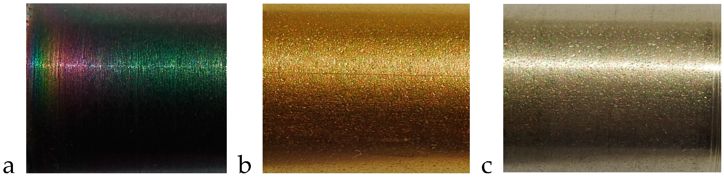
- CrN+OX (thickness: 9 μm, colour: rainbow);
- TiN (thickness: 3.5 μm, colour: yellow–gold);
- ZrN (thickness: 2.5 μm, colour: golden white).
The macroscopic images of the coated shaft surfaces are shown in Figure 1.

Figure 1.
The view of the shaft surface with a coating applied; (a) CrN+OX, (b) TiN, (c) ZrN.
The test model was assembled by forcing the sleeve onto the shaft with the use of a hydraulic press recording the value of the pressing force in the function of the length of the connection. The maximum values of the pressing force for the various samples are presented in Table 1.

Table 1.
Maximum values of the force pressing the sleeve onto the shaft.
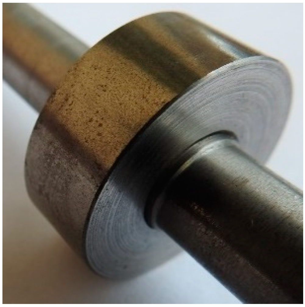
The tolerance was taken at 0.02 mm, for which the surface pressure is 130.8 MPa. The calculated surface pressure is close to the value of surface pressures in the real wheel set. Figure 2 shows the photo of the sleeve and shaft press-in connection for wear tests.

Figure 2.
The view of the tribological kinematic pair.
Fatigue tests were conducted on a UB-M fatigue machine.
The machine enables the generation of a periodically variable load with the pure bending of a rotating sample. The fatigue cycle is performed by bending a rotating sample under a constant load in one plane, where the upper layers are compressed and the lower ones stretched. The machine enables double-side sample fixing, in which the bending moment is constant over the entire sample length, or single-side fixing, where the bending moment is variable. For the purposes of this work, the double-side sample fixing was used.
The fatigue test parameters were as follows:
- load on the tribological kinematic pair—550 N;
- maximum bending moment following from the load on the sample—27.5 Nm;
- stress amplitude—162 MPa (for the 12 mm shaft diameter) and 128 MPa (for the 13 mm shaft diameter);
- number of cycles—8.5 × 10⁶.
The load on the sample is close to the actual load on the wheel set of a rail vehicle moving along a straight track, i.e., in the case where lateral forces originating, for example, from the hunting oscillation of the vehicle, do not act on the wheel set.
It is only possible to obtain the oscillatory tangential displacements when one of the mated elements is subjected to bending during wear tests. In the case under analysis, this will be the shaft. The load on the connection should ensure shaft deflection, but it should not cause plastic deformations. To analyse the distribution of reduced stresses on the shaft and sleeve surfaces for the load taken, and to analyse shaft deflection and assess fatigue strength, a computer simulation was conducted with the use of ANSYS 2022 R1 software. The reduced stresses on the shaft and sleeve surfaces are similar to each other. In the case of the shaft, the maximum stress value is 318.71 MPa and that value occurs at the point of change of the cross-section diameter, therefore, at the place where the notch phenomenon might occur. In the case of the sleeve, the maximum stress value is 308.74 MPa, and that value occurs over the entire hub circumference.
To evaluate shaft surface damage, the following laboratory investigations and observations were conducted:
- axle seat surface-roughness measurement conducted before the connection was assembled. The measurement was performed with the Hommel—Etamic W5 profilometer by Jenoptik owned by the Faculty of Mechanical Engineering of the Krakow University of Technology, Cracow, Poland;
- macroscopic observations of the shaft axle seat surfaces before and after wear tests. Such observations were conducted with a camera with the zoom ×83 function, by Nikon owned by the Faculty of Engineering Sciences, State University of Applied Sciences in Nowy Sącz, Poland;
- microscopic observations of the shaft axle seat surface before and after wear tests, with the use of the JEOL JSM-6460LV scanning electron microscope owned by the Faculty of Engineering Sciences, State University of Applied Sciences in Nowy Sącz, Poland;
- qualitative and quantitative micro-analysis of the chemical composition of substances at the axle seat surface within the area of wear traces, conducted by means of the JEOL JSM-6460LV scanning electron microscope equipped with an EDS INCA x-act Energy 350 spectrometer owned by the Faculty of Engineering Sciences, State University of Applied Sciences in Nowy Sącz, Poland;
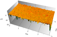
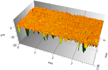
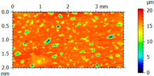
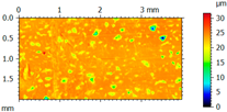
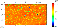
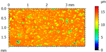
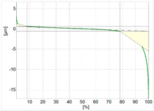
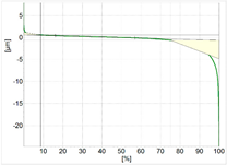
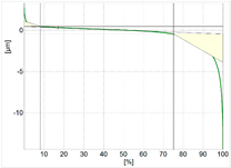
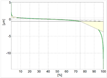
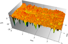
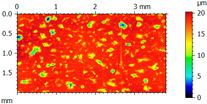
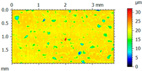
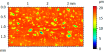
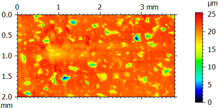
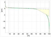
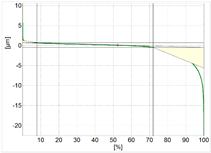
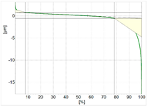
- top layer typography measurement after the assembly of the connection and after wear tests. The measurements were performed with the use of a TOPO 01P contact profilometer equipped with an induction-measuring head with a 2 μm radius and 90° cone angle. The results were presented as a roughness profile, material ratio curve, and contour maps. The selected 3D shaft surface-roughness parameters were also indicated.
3. Results and Discussion
3.1. Macroscopic Observations
In Figure 3, the results of macroscopic observations of the shaft surfaces are presented with a coating and, for comparison, the uncoated shaft surface.
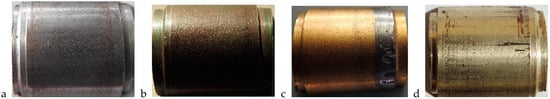
Figure 3.
Macroscopic images of shaft surfaces after wear tests, (a) shaft without coating, (b) shaft with CrN+OX coating, (c) shaft with TiN coating, (d) shaft with ZrN coating.
The macroscopic images of uncoated shafts depict fretting wear on either side of the shaft axle seat. Wear occurs at the entire circumference of the axle seat in the form of a 3–4 mm wide ring; however, that width is different on either side. The traces of wear at the edge of the connection follow from the fretting-wear development mechanism in press-in connections, which is discussed in detail by Guzowski S. in his publications, and which may be presented in the following way. As a result of model rotation during operation, and due to the occurrence of oscillatory tangential displacements, the products of the press-in process, present at the connection edge, are removed towards the outside. Due to that, direct contact between the shaft and sleeve surfaces takes place, which creates advantageous conditions for the development of adhesive bonds that cause the destruction of the top layer.
The traces of wear are brown, which is a colour typical of the atmospheric corrosion of iron, that being the evidence of the damaged area’s oxidation. Oxide formation is linked to the existence of a gap between the shaft and sleeve surfaces, which comes into being as a result of sample bending, thus enabling contact of the damaged areas with oxygen.
The images of the shaft surface with a CrN+OX coating indicate fretting wear in the form of a regular ring comprising the entire hub and axle-seat circumference, especially on the right side of the sample. The colours of wear traces and of the coating applied onto the shaft merge with each other, thus causing difficulties with the correct interpretation of the shaft surface wear. Under operation conditions, this situation is all the more dangerous as unnoticed fretting wear can, over time, contribute to the development of fatigue wear.
The use of an oxide layer on the coating surface has had the effect of reducing the fretting wear of the shaft. The ring of wear traces observed on the right side of the sample starts at a distance of 2 mm from the edge of the axle seat and is 3 mm wide. The left side of the sample is distinguished by lower wear intensity. In that case, the wear ring width varies between 2–2.3 mm, and the ring also starts at a distance of 2 mm from the edge.
All the analysed shaft surfaces with the TiN coating are noted for considerable damage. The first, and most conspicuous instance of damage, is the destruction of the surface on the left side of the sample. This is distinguished by coating tearing or a considerable build-up of material from the sleeve top layer. The nature of the damage may be studied in detail during microscopic observations. The following causes of damage were considered. As the first cause, errors in shaft or sleeve manufacture were pointed out, in particular the lack of the required dimensional tolerance. However, all the components were made on CNC machines with high accuracy; therefore, that assumption may be disregarded. In turn, the incorrect manufacture of the components would affect the assembly of the connection. During forcing in, too close a fit could lead to the destruction of the top layer in a way similar to that shown in the figure. The wear trace direction, however, does not indicate assembly damage. In that case, the traces would have been perpendicular to the shaft axis.
Most probably, damage occurred at the operation stage (during the wear tests). The traces indicate the reduction of assembly pressures, which come into being during sleeve forcing onto the shaft, as a result of the connection becoming loose. The sleeve rotating on the shaft during operation could cause similar damage. If this assumption is taken as the most probable one, a question arises as to why similar damage does not occur on the other side of the sample or at any other place. At this stage of research, it is difficult to explain the cause and mechanism of damage in a rational way. That is why the analysis of that damage will be the subject matter of relevant research in the future.
At the axle seat and sleeve surfaces, visible are also traces resembling fretting wear. They occur at a distance of 40–50 mm from the edge of the connection, on either side, as a 2 mm ring comprising the entire sleeve circumference. On the left side of the sample, the traces are more conspicuous, and the areas of higher wear intensity appear in places. In accordance with the fretting-wear development mechanism in press-in connections, the maximum slide amplitude occurs close to the edge of the connection and is near zero at the place of the visible traces. Therefore, the noted wear traces are not the effect of fretting wear.
In the case of shafts with the ZrN coating, fretting-wear traces are visible on either side of the shaft axle seat over the entire shaft circumference, at a distance of 8–10 mm from the edges. The distribution of fretting-wear traces is random in nature. On the right side of the sample, the local occurrence of wear traces is noted, with periodic high wear intensity. The area of the greatest wear region is approximately 0.75 cm2, and it can be seen on the right side of the axle seat. On the left side of the sample, wear is less intensive and, like on the right side, is distinguished by irregular shapes. Moreover, on the left side of the sample, wear micro-traces extending towards the shaft centre may be noted.
In addition to damage related to fretting wear, on the right side of the shaft, there is visible damage, which most probably occurred during the assembly of the connection. A dozen or so scratches of various lengths appear around the entire shaft circumference, perpendicular to the axis of symmetry of the shaft. The groove depth varies and generally is not greater than several micrometres, but one of them is very peculiar. Over five centimetres, the scratch depth is the biggest and it reaches as far down as the base surface of the coating, thus exposing the steel surface; then, the depth decreases to micrometres until the scratch disappears completely. This situation is undesirable because of the strength of the connection. During operation, additional focuses of fatigue, which may accelerate the development of fretting wear and lead to shaft cracking, may come into being at that place.
3.2. Measurement of Surface Roughness and Hardness
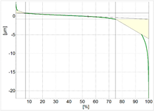
The results of the shaft surface-roughness measurement before and after wear tests are summarised in Table 2a,b. The surface-roughness measurements after wear tests were performed in the fretting-wear zone. The roughness measurement was carried out on the shaft surface, using a measurement section of 2 × 4 mm.
Table 2.
a. The results of shaft surface-roughness measurements. b. The results of shaft surface-roughness measurements, continued.
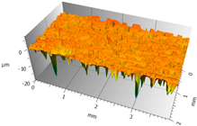
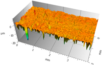
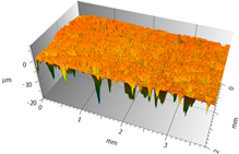
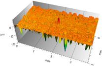
The topographies of all the surfaces and all the roughness parameters change their appearance and value after wear tests in relation to the surfaces before testing. Both the dimensions and the position of local elevations and cavities change.
When analysing the diagrams showing the surface-roughness spatial profile and contour maps, it is possible to note changes in the position of local elevations and cavities. The size and density of the single fields visibly changed. As regards the analysed section covered by the measurements, more elevations are noted on the shaft surface after wear tests. The change in shaft surface topography is due to the formation of new areas covered with micro-irregularities, which originate from the abrasion of protrusions located on the surfaces of the mating components. Displaced wear products stick to the surface, thus creating uneven areas filled with build-ups.
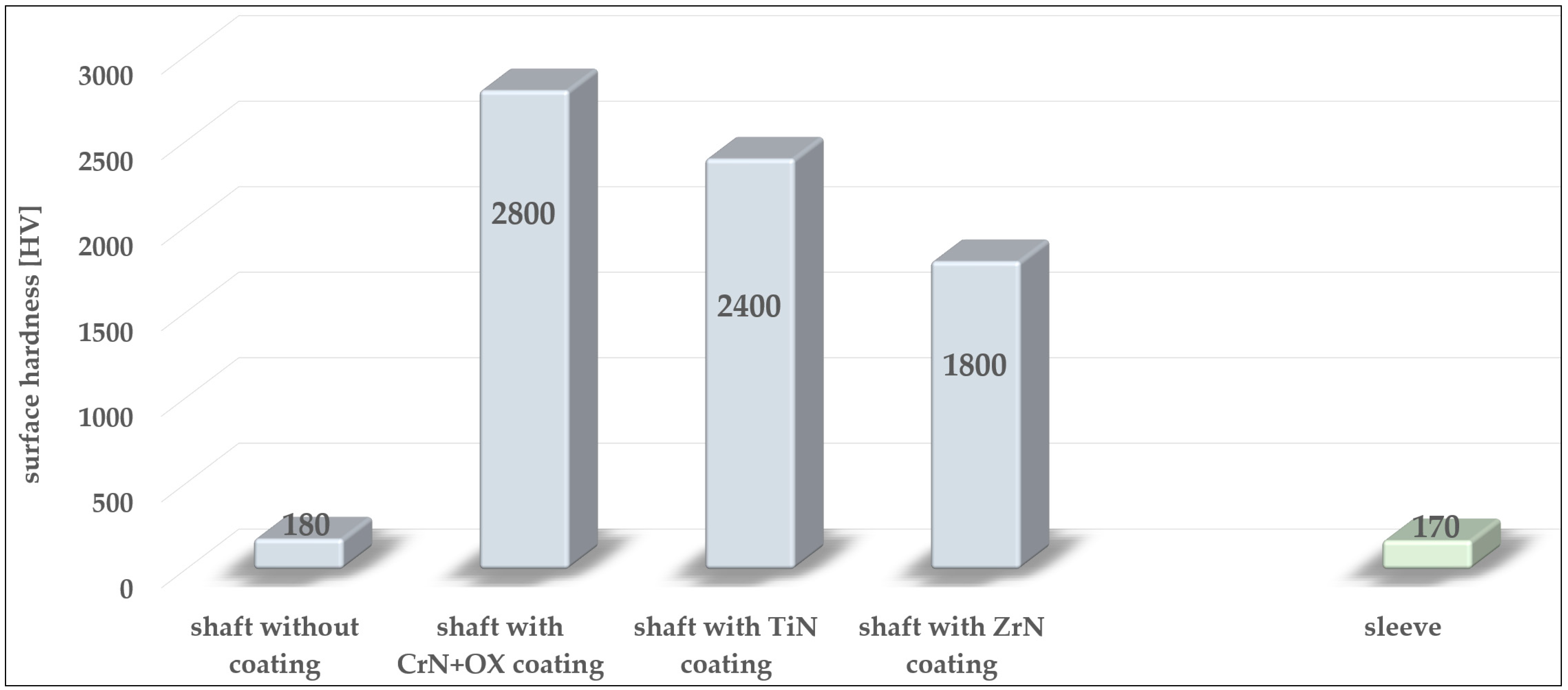
In the case of coated shafts, clear changes in volume are visible. It is noted that micro-holes in the coating are filled with powdered wear products displaced by micro-vibrations. Those products most likely originate from the shearing of the surface irregularities on the sleeve. This statement may be justified by the significant difference in the hardness of the mating surfaces. In Figure 4, the surface hardnesses of the shafts and sleeves analysed in this article are compared.
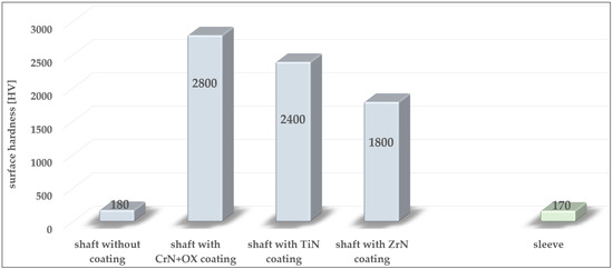
Figure 4.
Shaft and sleeve surface hardnesses.
The shaft with a CrN+OX coating is distinguished by the biggest difference in surface hardness, that being 2800 HV. That value follows from the presence of oxides on the surface of the coating. A difference in hardness of at least ten times between the surfaces of the coated shafts and the surfaces of the sleeves will cause sleeve wear in the first place. Therefore, the build-ups on the shaft surfaces will mostly originate from the shearing of micro-irregularities on the sleeve surface.
3.3. Microscopic Observations
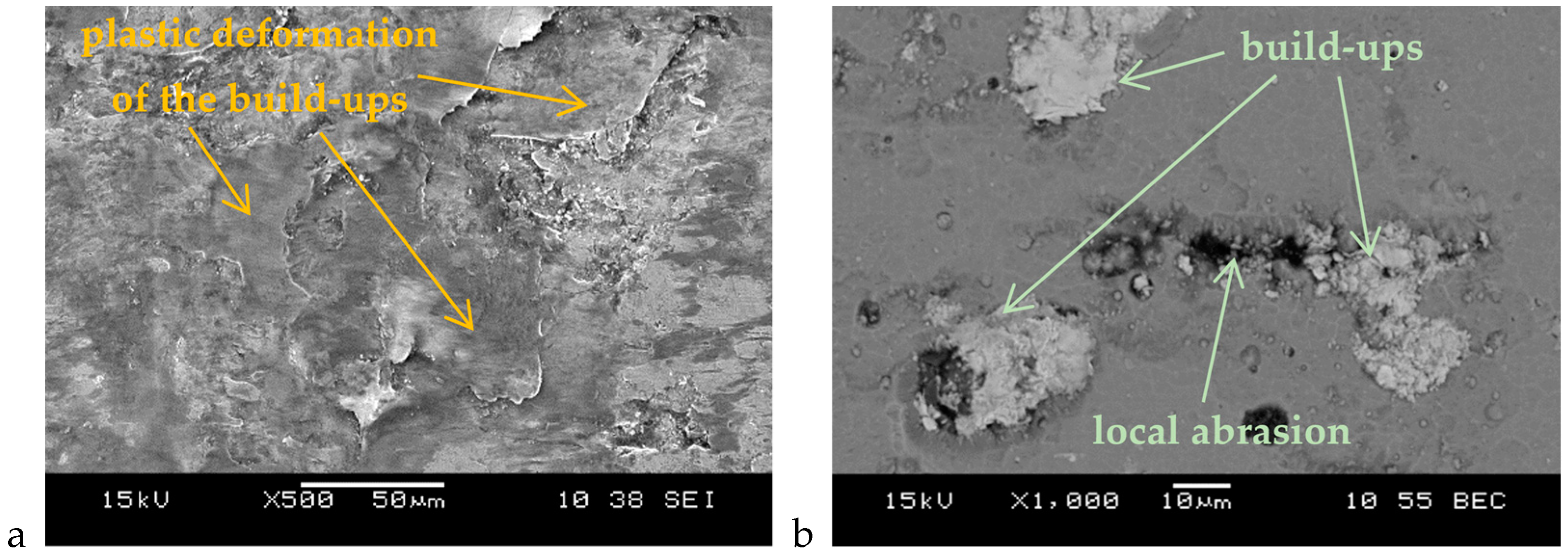
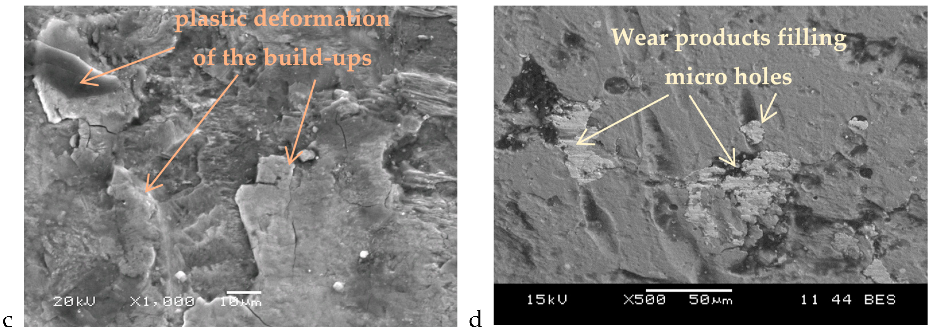
The wear-affected areas on the shaft surfaces were subjected to microscopic observations. The sample results of those observations are shown in Figure 5. The most frequently noted image shows material build-ups. They occur on all observed surfaces and occupy 80% of the worn-out area. The build-ups are of various sizes and colours. The colour of the build-ups depends on the degree of their oxidation. Those with a lower degree of oxidation have a lighter colour, and those more oxidised are darker.

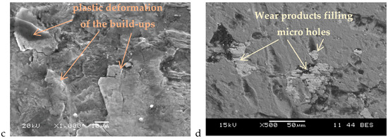
Figure 5.
The sample microscopic images of shaft surfaces, (a) the uncoated shaft, (b) the shaft with a CrN+OX coating, (c) the shaft with a TiN coating, and (d) the shaft with a ZrN coating.
During wear tests, the mating components are subjected to oscillatory tangential displacements which are conducive to the plastic deformation of the build-ups trapped between those components. Some of those build-ups tend to crack and move to other areas of the shaft surface.
In addition to the material build-ups mentioned previously, it is also noted that the micro-holes occurring at the coating surface are filled with wear products, which are mainly made up of the shorn micro-irregularities on the sleeve surface. The filling of micro-holes with wear products causes the surfaces of the shafts to become “smoother”, thus reducing roughness parameters. This is not an advantageous phenomenon because, in the case of a tribological kinematic pair subjected to loads following from rotational bending; a bigger contact area of the mating components means that adhesion may develop. Adhesive bonds will then be another factor conducive to further damage to the mating components.
The images of the worn-out surface, as mentioned and discussed above, concern all the shafts under analysis. In the case of uncoated shafts, more damage in the form of local abrasion and micro-pits is visible. Surface abrasion may be the result of micro-machining processes, where oxidised wear products, distinguished by greater hardness than the sleeve or shaft surface, are the cutting element.
The above images were not observed in the case of coated shafts, as the hardnesses of their surfaces prevented the “weaker” wear products originating from shearing the micro-irregularities of the sleeve surface from grooving or scratching those surfaces.
The damage arising on the surface may, under fatigue-loading conditions, become a focus of the development of fatigue cracks.
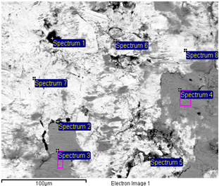
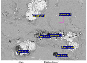
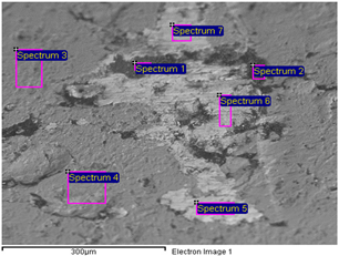
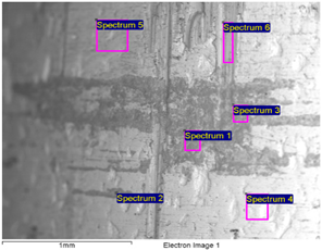
3.4. Analysis of the Chemical Composition of Wear Products
In order to quantify the chemical composition of the wear products found on the surfaces of the shafts, an EDS micro-analysis was performed. Table 3a–d summarises the percentage content of chemical elements present in the fretting-wear zone, including the wear products.
Table 3.
a. The results of the micro-analysis of the chemical composition of wear products (the uncoated shaft) [%]. b. The results of the micro-analysis of the chemical composition of wear products (the shaft with a CrN+OX coating) [%]. c. The results of the micro-analysis of the chemical composition of wear products (the shaft with a TiN coating) [%]. d. The results of the micro-analysis of the chemical composition of wear products (the shaft with a ZrN coating) [%].
The results of the analysis of the chemical composition of wear products on the shaft surfaces confirm their oxidation. That statement is proven by oxygen atoms displayed on each sample that has been examined. Those atoms, together with iron, form very hard iron oxides, Fe3O2. It is precisely those oxides, among others, that are responsible for damage to the top layer of the mating components, such as scratches and micro-cracks.
The analysis of the chemical composition also confirmed that the wear products filling the micro-holes on coated shaft surfaces mainly originate from shearing the micro-irregularities on the sleeve surfaces. That phenomenon is particularly well visible on the surface of the shaft with a CrN+OX coating (Figure 5b, Table 3b) and of the shaft with a TiN coating (Figure 5c, Table 3c), where the wear products are made of oxygen and/or iron atoms.
3.5. Wear Mechanism for the Top Layer of the Mating Components
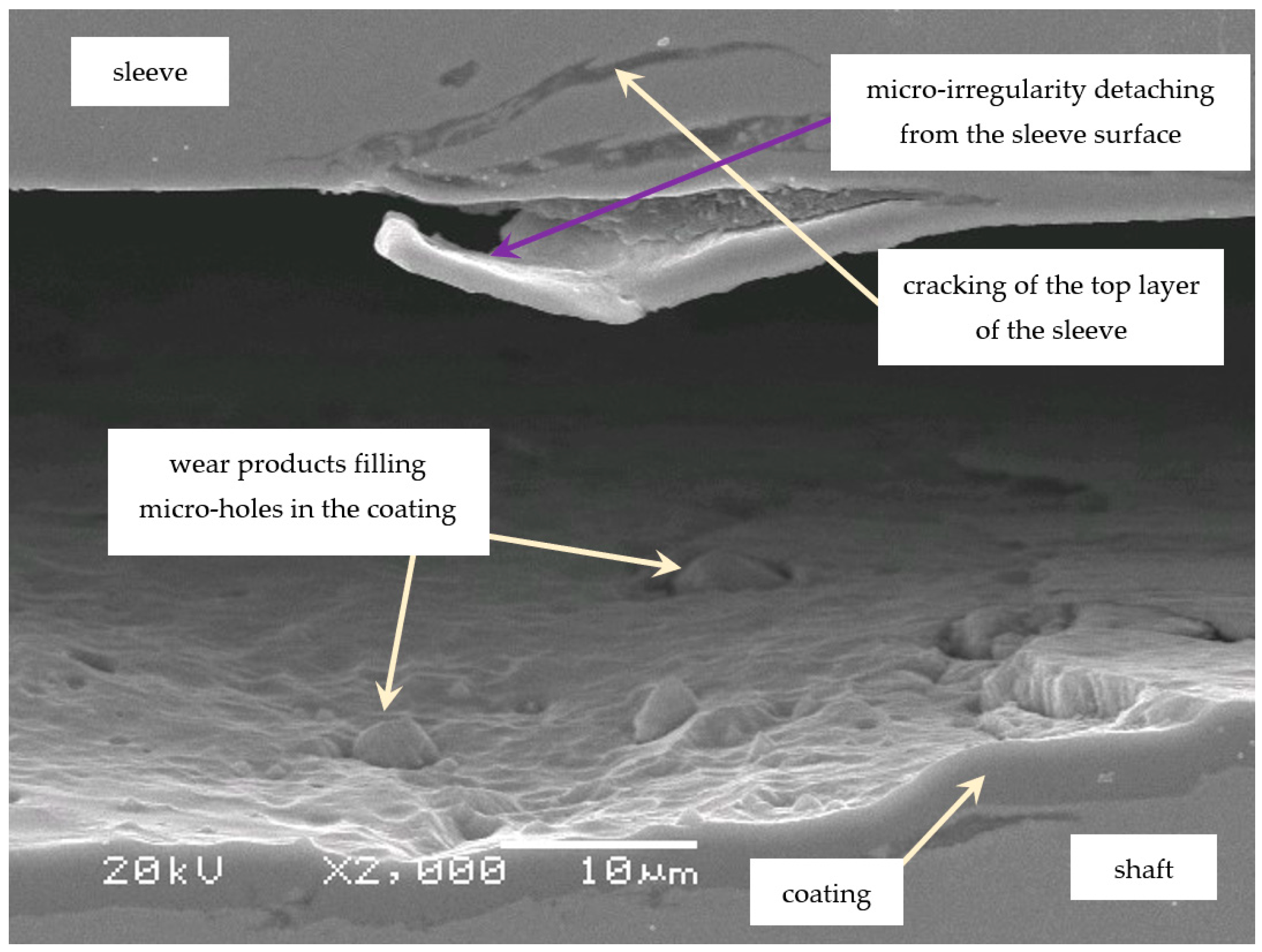
Figure 6 shows the connection between the sleeve and shaft depicting the tearing mechanism for micro-projections and their travel along the connection during wear tests.
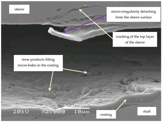
Figure 6.
The image shows the sleeve and shaft connection with visible wear products.
Micro-projections are shorn mainly during the assembly of the connection, i.e., when the sleeve is pressed onto the shaft, thus generating wear products. During the wear tests, oxidised products travel along the connection, causing the damage to both mating surfaces, with the sleeve surface being more exposed to wear, as its hardness is lower. Due to the activity of oscillatory tangential displacements of the elements of the tribological kinematic pair, the displacement and disintegration of the wear products take place. Some of them fill the micro-holes in the surface and, thus, make the surface smooth. A greater contact area between the mating components will be conducive to the formation of adhesive bonds affecting the life of the top layer of the components. Weakened due to adhesion and scratches, the surface will, over time, be liable to fatigue cracks, whose initiation starts at the surface of the component. In the next stage, the cracks develop and move deeper into the top layer at approximately 36°.
4. Conclusions
The aim of the research in this article was to assess the influence of selected coatings made with PVD technology on the wear of a press-in connection operating in rotational bending conditions.
The test results demonstrated the presence of fretting wear on all the examined surfaces. The image of fretting wear comprises damage caused by adhesion, plastic deformation, oxidation, and micro-machining. In all the examined samples, fretting wear occurs at the edges of the connection, which follows from the wear development mechanism described in the literature. The location of the wear traces confirms that the assumptions and test methodology are correct.
All the observed surfaces in the fretting-wear area have a brown colour, indicating oxidation of the wear products present in that area.
Microscopic observations showed that the predominant damage is the formation of material build-ups on the surfaces of the shafts, which undergo plastic deformation and oxidation.
The use of coatings reduces the development of fretting wear. However, due to the large difference in surface hardness, damage to the sleeve top layer and the movement of wear products along the connection occurs.
TiN coatings incurred further damage, which may be due to the assembly process or occurred during operation. Wear-product migration caused a change in the shaft surface profile. The coating was torn off completely in places. The unclear image of wear will constitute the research material presented in subsequent publications.
In the case of the coatings, fretting wear is randomly distributed around the circumference of the shafts; while in the case of uncoated shafts, fretting wear takes the form of a ring of varying width covering the entire shaft circumference.
Funding
This research received no external funding.
Institutional Review Board Statement
Not applicable.
Informed Consent Statement
Not applicable.
Data Availability Statement
Data are contained within the article.
Conflicts of Interest
The authors declare no conflict of interest.
References
- Suchý, L.; Knabner, D.; Hasse, A. Fretting fatigue of multiaxially loaded shrink-fit connections—The effect of material sensitivity on fatigue strength. Procedia Struct. Integr. 2022, 42, 1128–1136. [Google Scholar] [CrossRef]
- Falter, J.; Binz, H.; Kreimeyer, M. Investigations on design limits and improved material utilization of press-fit connections using elastic-plastic design. Appl. Eng. Sci. 2023, 13, 100124. [Google Scholar] [CrossRef]
- Dong, Y.; Zeng, D.; Wu, P.; Lu, L.; Zou, L.; Xu, T. Numerical prediction of fretting fatigue crack growth in scaled railway axles considering fretting wear evolution. Int. J. Fatigue 2024, 181, 108150. [Google Scholar] [CrossRef]
- Ren, Y.; Nie, H.; Dong, Y.; Xu, X.; He, J.; Li, Z.; Cai, Z.; Shen, H.; Zhu, M. Fretting wear behavior of different surface modified layers of a tight fit spline used for a gauge-changeable railway vehicle. Tribol. Int. 2024, 193, 109359. [Google Scholar] [CrossRef]
- Aliakbari, K.; Abbasnia, S.K.; Nejad, R.M.; Manoochehri, M. Analysis of stress intensity factors in railway wheel under the influence of stress field due to heat treatment and press-fitting process. Eng. Fail. Anal. 2021, 130, 105736. [Google Scholar] [CrossRef]
- Čapek, J.; Trojan, K.; Kec, J.; Ganev, N.; Černý, I.; Mužík, T. Residual Stresses and the Microstructure of Modeled Laser-Hardened Railway Axle Seats under Fatigue. Metals 2024, 14, 290. [Google Scholar] [CrossRef]
- Xin, L.; Han, Y.; Lin, L.; Zhang, W.; Lu, Y.; Shoji, T. The Evolution of Fretting Wear Behavior and Damage Mechanism in Alloy 690TT with Cycle Number. Materials 2020, 13, 2417. [Google Scholar] [CrossRef] [PubMed]
- Kowalski, S. Application of dimensional analysis in the fretting wear studies. J. Balk. Tribol. Assoc. 2016, 22, 3823–3835. [Google Scholar]
- Sharma, A.; Sadeghi, F. Effects of fretting wear on rolling contact fatigue. Tribol. Int. 2024, 192, 109204. [Google Scholar] [CrossRef]
- Pinto, A.L.; Araújo, J.A.; Talemi, R. Effects of fretting wear process on fatigue crack propagation and life assessment. Tribol. Int. 2021, 156, 106787. [Google Scholar] [CrossRef]
- Argatov, I.; Chai, Y.S. Contact Geometry Adaptation in Fretting Wear: A Constructive Review. Front. Mech. Eng. 2020, 6, 51. [Google Scholar] [CrossRef]
- Chyła, K.; Gaska, K.; Gronba-Chyła, A.; Generowicz, A.; Grąz, K.; Ciuła, J. Advanced Analytical Methods of the Analysis of Friction Stir Welding Process (FSW) of Aluminum Sheets Used in the Automotive Industry. Materials 2023, 16, 5116. [Google Scholar] [CrossRef] [PubMed]
- Lavella, M.; Botto, D. Fretting wear damage mechanism of CoMoCrSi coatings. Wear 2021, 477, 203896. [Google Scholar] [CrossRef]
- Kowalski, S.; Opoka, K.; Ciuła, J. Analysis of the end-of-life the front suspension beam of a vehicle. Eksploat. Niezawodn.–Maint. Reliab. 2022, 24, 446–454. [Google Scholar] [CrossRef]
- Michnej, M.; Guzowski, S. Fretting wear simulation in a clamped joint based on the example of a rail vehicle wheel set. Wear 2019, 438–439, 102654. [Google Scholar] [CrossRef]
- Muhammed, M.; Javidani, M.; Ebrahimi Sadrabadi, T.; Heidari, M.; Levasseur, T.; Jahazi, M. A Comprehensive Review of Cathodic Arc Evaporation Physical Vapour Deposition (CAE-PVD) Coatings for Enhanced Tribological Performance. Coatings 2024, 14, 246. [Google Scholar] [CrossRef]
- Hadło, K.; Lubas, J.; Szczypinski-Sala, W.; Tomala, A.; Konieczny, D. Tribological Properties of a Sliding Joint with an a-C:H:W Coating under Lubrication Conditions with PAO8 Oil and the Addition of 2% MoS2 Nanoparticles. Materials 2024, 17, 870. [Google Scholar] [CrossRef]
- Grąz, K.; Generowicz, A.; Kwaśny, J.; Gronba-Chyła, A.; Kwaśnicki, P.; Ciuła, J.; Łapiński, J.; Bajdur, W. Microplastics from Plastic Waste as a Limitation of Sustainability of the Environment. Rocz. Ochr. Srodowiska 2023, 25, 367–373. [Google Scholar] [CrossRef]
- Staszuk, M. Investigations of CrN+Cr2O3/TiO2 coatings obtained in a PVD/ALD hybrid method on austenitic 316L steel substrate. Vacuum 2023, 207, 111653. [Google Scholar] [CrossRef]
- Kao, W.H.; Su, L.Y.; Lin, Y.J. Mechanical, Tribological, and Anti-corrosion Properties of Nitrogen-Doped AlCrNbSiTiMoW High-Entropy Coatings. Mater. Chem. Phys. 2022, 282, 125999. [Google Scholar] [CrossRef]
- Yang, D.; Yan, F.; Zhang, W.; Xie, Z. Microstructure, Wear Resistance and Corrosion Resistance of CrN Coating with Platinum Iridium Co-Doping. Coatings 2024, 14, 238. [Google Scholar] [CrossRef]
- Du, J.W.; Chen, L.; Chen, J.; Du, Y. Mechanical properties, thermal stability and oxidation resistance of TiN/ CrN multilayer coatings. Vacuum 2020, 179, 109468. [Google Scholar] [CrossRef]
- Li, M.; Yu, Y.; Zou, C.; Tian, C.; Xiang, Y. Tribological and Corrosion Performance of CrAlN/CrN Coatings in Artificial Seawater under Varied Nitrogen Pressures. Coatings 2023, 13, 2090. [Google Scholar] [CrossRef]
- Chen, Y.; Wang, S.; Hao, Y.; Pu, J.; Jiang, X.; Huang, L.-F.; Wang, L. Friction and Wear Behavior of CrN Coating on 316L Stainless Steel in Liquid Sodium at Elevated Temperature. Tribol. Int. 2020, 143, 106079. [Google Scholar] [CrossRef]
- Bai, H.; Li, J.; Gao, J.; Ni, J.; Bai, Y.; Jian, J.; Zhao, L.; Bai, B.; Cai, Z.; He, J.; et al. Comparison of CrN Coatings Prepared Using High-Power Impulse Magnetron Sputtering and Direct Current Magnetron Sputtering. Materials 2023, 16, 6303. [Google Scholar] [CrossRef] [PubMed]
- Hussein, M.A.; Adesina, A.Y.; Kumar, A.M.; Sorour, A.A.; Ankah, N.; Al-Aqeeli, N. Mechanical, in-vitro corrosion, and tribological characteristics of TiN coating produced by cathodic arc physical vapor deposition on Ti20Nb13Zr alloy for biomedical applications. Thin Solid Film. 2020, 709, 138183. [Google Scholar] [CrossRef]
- Yuan, Z.; Han, Y.; Zang, S.; Chen, J.; He, G.; Chai, Y.; Yang, Z.; Fu, Q. Analysis of the mechanical properties of TiN/Ti multilayer coatings using indentation under a broad load range. Ceram. Int. 2021, 47, 10796–10808. [Google Scholar] [CrossRef]
- Kowalski, S.; Cygnar, M.; Cieślikowski, B. Analysis of the application of ZrN coatings for the mitigation of the development of fretting wear processes at the surfaces of push fit joint elements. Proc. Inst. Mech. Eng. Part J J. Eng. Tribol. 2020, 234, 1208–1221. [Google Scholar] [CrossRef]
- Tien, C.-L.; Chiang, C.-Y.; Lin, S.-C. Optimization of Electron-Beam Evaporation Process Parameters for ZrN Thin Films by Plasma Treatment and Taguchi Method. Plasma 2023, 6, 478–491. [Google Scholar] [CrossRef]
- Özkan, D.; Yilmaz, M.A.; Karakurt, D.; Szala, M.; Walczak, M.; Bakdemir, S.A.; Türküz, C.; Sulukan, E. Effect of AISI H13 Steel Substrate Nitriding on AlCrN, ZrN, TiSiN, and TiCrN Multilayer PVD Coatings Wear and Friction Behaviors at a Different Temperature Level. Materials 2023, 16, 1594. [Google Scholar] [CrossRef]
- Frank, F.; Kainz, C.; Tkadletz, M.; Czettl, C.; Pohler, M.; Schalk, N. Microstructural and micro-mechanical investigation of cathodic arc evaporated ZrN/TiN multilayer coatings with varying bilayer thickness. Surf. Coat. Technol. 2022, 432, 128070. [Google Scholar] [CrossRef]
- Cai, F.; Zhou, Q.; Chen, J.; Zhang, S. Effect of inserting the Zr layers on the tribo-corrosion behavior of Zr/ZrN multilayer coatings on titanium alloys. Corros. Sci. 2023, 213, 111002. [Google Scholar] [CrossRef]
- Kowalski, S. Assessment of the possibility of the application of a CrN+OX multi-layer coating to mitigate the development of fretting wear in a press-fit joint. Wear 2018, 398–399, 13–21. [Google Scholar] [CrossRef]


Disclaimer/Publisher’s Note: The statements, opinions and data contained in all publications are solely those of the individual author(s) and contributor(s) and not of MDPI and/or the editor(s). MDPI and/or the editor(s) disclaim responsibility for any injury to people or property resulting from any ideas, methods, instructions or products referred to in the content. |
© 2024 by the author. Licensee MDPI, Basel, Switzerland. This article is an open access article distributed under the terms and conditions of the Creative Commons Attribution (CC BY) license (https://creativecommons.org/licenses/by/4.0/).