Abstract
To investigate the effect of ZrC on the ablative properties of C/SiC composites in a high-temperature environment, the oxidative ablation of C/SiC and C/SiC-ZrC composites at high-temperatures was examined through ablation tests. In this study, two ceramic matrix composites, C/SiC and C/SiC-ZrC, were prepared by chemical vapor deposition and precursor impregnation pyrolysis. The ablation properties of the materials were tested and analyzed using an oxyacetylene flame to simulate a high-temperature environment. The results revealed that the line ablation rate of C/SiC-ZrC was 8.48% and 20.81% lower than that of C/SiC at 30 s and 60 s, respectively. At the same ablation time, the depth of the crater resulting from erosion of the C/SiC material by the high-temperature airflow was deeper than that of C/SiC-ZrC. The traces of the fibers subjected to erosion were more prominent. In a longitudinal comparison, the mass ablation rate of C/SiC-ZrC material decreased with the increase in time, while the line ablation rate initially increased rapidly and then decreased. From 30 s to 90 s of ablation, the line ablation rate and mass ablation rate decreased by 55.62% and 89.5%, respectively. The overall trend for both rates was a decrease with the increase in time. Under the same ablation time, the ablation rate of C/SiC-ZrC was generally lower than that of C/SiC. This is because the generated molten ZrO2 was more viscous and denser than SiO2, effectively blocking oxidizing gases from penetrating the interior of the material. The molten ZrO2 provided better protection for the substrate in the high-temperature environment.
1. Introduction
With the vigorous development of aerospace science and technology, the speed of vehicles has reached as high as Mach 5, resulting in increasingly harsh working conditions for hypersonic vehicles [1,2,3]. The erosion of materials by high-temperature airflow seriously affects the structural life and safety of the vehicle, posing a great challenge to the high-temperature materials [4,5]. Traditional high-temperature alloys, C/C composites, and graphite have difficulty meeting the requirements. C/SiC, due to its good high-temperature resistance, oxidation resistance, and excellent ablation resistance, is widely recognized as the most promising thermal protection material [6,7,8,9]. C/SiC has been initially applied to the nose cones of intercontinental missiles, the end cowl of the X-38 vehicle, the gas rudders of rockets, and parts such as Laval nozzles [10,11,12].
At present, C/SiC composites are considered to be able to work at 1650 °C for a long time, but once they exceed 1650 °C, the material reacts violently with oxygen, and the carbon fibers surrounded by the matrix exhibit serious oxidation. At the same time, under high-temperature gas scrubbing, the surface of the material undergoes obvious ablation, which alters the material’s morphology as well as its physical properties, and thereby reduces its mechanical properties. Therefore, it is crucial to study the mechanism of thermal ablation for understanding the oxidation and ablation phenomena of materials in a high-temperature environment. Currently, the main test methods for evaluating the ablation properties of materials are plasma ablation, oxygen–acetylene ablation, and electric arc ablation. Among these, the oxygen–acetylene ablation test method is widely used in ablation tests due to its simple test device and low cost. In recent years, many scholars have conducted in-depth studies on the ablation properties and mechanisms of C/SiC, C/C, C/C-SiC, and SiC/SiC composites in high-temperature environments [13,14,15,16,17]. It is generally believed that ablation is caused by the combined effect of mechanical scouring, physical sublimation, and thermochemical reaction. Chen [18] used an oxygen–acetylene flame to create two different high-temperature ablation environments at 2900 °C and 3550 °C for C/SiC materials. At 2900 °C, thermal decomposition and oxidation of the SiC matrix dominated the overall ablation behavior, while sublimation of the SiC matrix was the primary ablation behavior above 3550 °C, thus revealing the ablation behavior of C/SiC at different temperatures. Lee [19] investigated the ablation properties of C/C materials coated with SiC and found that the presence of a SiC coating favors the inhibition of oxidation in C/SiC, resulting in better ablation resistance. Xiang [20] investigated the ablation oxidation behavior of C/SiC materials coated with two different coatings and found that the mass loss rate of the uncoated C/SiC material was as high as 13.19%, whereas the mass loss rate of the SiC-coated C/SiC material was 4.6%, and the mass loss rate of the C/SiC material coated with the ZrB2-SiC/SiC coating was only 0.4%, indicating that the ZrB2-SiC/SiC coating played a more effective role in protecting the material. Tang [21,22] investigated the SiO2 droplet/liquid film flow, fusion, and fluidic transition generated by ablation on the surface of C/SiC materials. These can be categorized into droplet flow, liquid flow, and liquid film flow according to the different forms of the flow. Additionally, the periodic K-H (Kelvin–Helmholtz) instability phenomenon at the gas–liquid interface was observed. Yu [23] not only studied the ablation morphology of SiC/SiC composites at 1800 °C but also investigated the flow mechanism of the liquid layer on the surface of the material at this temperature. He found that during the ablation process, due to the pressure difference between the inside and the outside and surface tension, the gas generated destroyed the continuity of the liquid film, allowing oxygen to continue attacking the internal material, thus weakening the material’s ablative resistance. To gain a clearer understanding of the ablation process, Fang [24] used a high-speed camera to record the thermal ablation process of C/SiC composites at 1800 °C, and found that the material formed a “pore” structure, surface cracks, and a “skeleton” structure after ablation. E. P. Simonenko [25,26] studied the long-term ablation behavior of ultra-high-temperature composite materials. The total time was more than 30 min. Under certain test conditions, some regions of the sample were found to experience a rapid increase in temperature up to 2700 °C.
A more in-depth investigation of the ablation behavior of C/SiC materials reveals that different partial pressures of oxygen lead to different oxidation reactions of SiC. The oxidation process is categorized into active and passive oxidation [27]. Active oxidation occurs in a low oxygen environment generates SiO, while passive oxidation takes place in a high oxygen environment, leading to the formation of SiO2. These products enhance the ablation resistance of C/SiC composites.
C/SiC composites exhibit good ablation resistance below 2000 °C. However, as the temperature continues to rise, the ablation resistance of C/SiC composites with a pure SiC matrix decreases significantly due to scouring by high-temperature and high-speed airflow, making it difficult to meet the requirements for good ablation resistance. Therefore, some domestic research institutions and universities have studied the ablation performance of ceramic matrix composites with the addition of refractory metal carbide. They found that the ablation resistance of C/SiC composites with the addition of an appropriate amount of ZrC refractory metal compounds is better than that of C/SiC materials without the addition. This enhanced ablation resistance allows the material to better withstand scouring by the airflow in a high-temperature environment.
To study the ablation mechanisms of C/SiC and C/SiC-ZrC composites, most scholars have primarily analyzed and discussed the materials based on their macroscopic and microscopic morphology after ablation, with few exploring the ablation properties and mechanisms through alternative means. In this study, a detailed macroscopic and microscopic observation of the two materials after ablation was conducted. The surface of the ablated materials was scanned and reconstructed using three-dimensional reconstruction technology. Additionally, the microstructures of the two materials were analyzed using an electron microscope and an energy spectrum analyzer. By comparing the ablation rates, the ablation parameters of C/SiC and C/SiC-ZrC materials were obtained, which demonstrates the influence of ZrC refractory metal compounds on the ablation properties of C/SiC composites. This approach allowed us to gain a deeper understanding of the ablation mechanisms of C/SiC and C/SiC-ZrC composites.
2. Materials and Test Procedure
2.1. Materials
C/SiC and C/SiC-ZrC ablation specimens were prepared by chemical vapor deposition and precursor impregnation pyrolysis (CVD + PIP) processes at the Institute of Metals, Chinese Academy of Sciences. The ceramic matrix composites consisted of a carbon fiber precursor, a pyrolytic carbon interface layer, and a silicon carbide matrix. The preparation process was as follows: Carbon fiber preform was used as the reinforcement. A layer of pyrolytic carbon was first deposited on the surface of the precast body. Then, the silicon carbide matrix was deposited via chemical vapor deposition (CVD), repeated several times to achieve densification. As shown in Figure 1, the needled 2D ceramic matrix composites consisted of alternating layers of 0° unidirectional fiber layers, mesh tire layers, and 90° unidirectional fiber layers, and both materials were reinforced with bundles of needled fibers in the thickness direction to prevent delamination. The volume fractions of the fibers, matrix, and pores of the ceramic matrix composites were 30%, 59%, and 11%, respectively. The density of the C/SiC composite was 1.90 g/cm3, and that of the C/SiC-ZrC composite was 1.95 g/cm3. The test specimens were machined to 30 × 30 × 3.5 mm3 and 30 × 30 × 5.1 mm3 using a UHP waterjet cutting process.
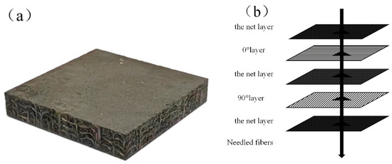
Figure 1.
The 2D needled composites: (a) physical drawing of the 2D needled composites; (b) schematic diagram of the 2D needled composites production process.
2.2. Ablation Test
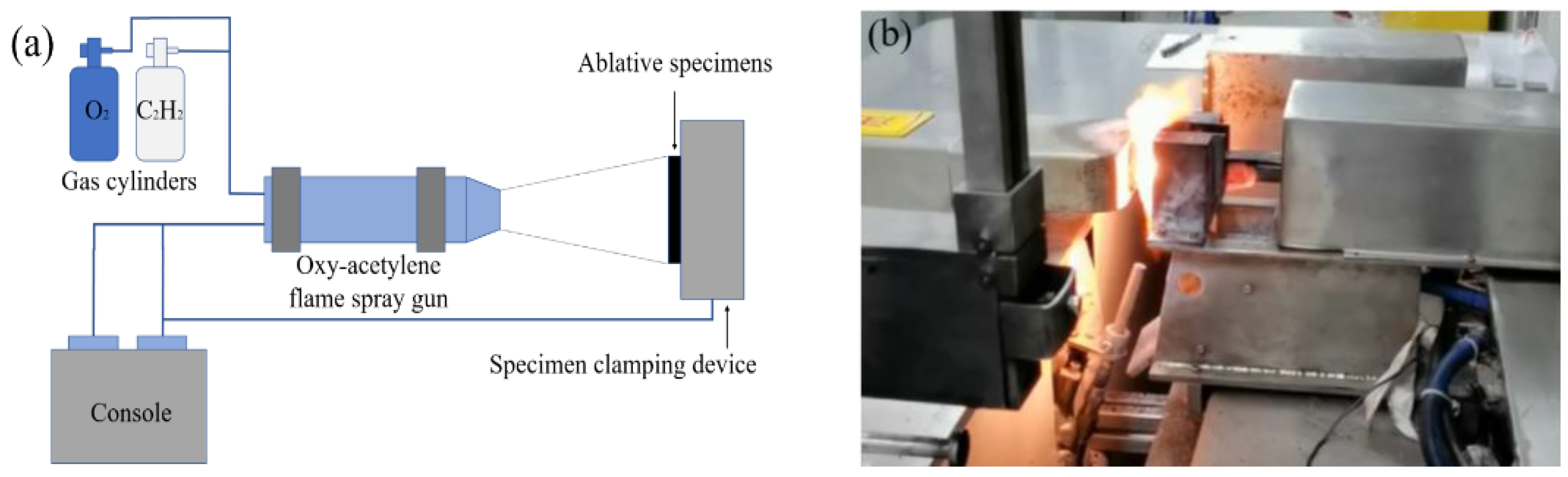
The ablation test was conducted using the test method outlined in the national military standard (GJB323A-1996) [28]. The entire specimen was exposed to an oxy–acetylene flame. The ablation test rig is depicted in Figure 2. The oxy–acetylene test rig comprised an oxy–acetylene gas unit, a control console, a flame gun, and a specimen-holding device. The gas heat flux was 4200 Kw/m2. The heat flux density was measured prior to the ablation test. Oxygen flow and acetylene flow were recorded when the heat flow density were achieved and stabilized. The oxygen flow rate and pressure required for a heat flux of 4200 Kw/m2 were 1512 L/h and 0.4 MPa, and the C2H2 gas flow rate and pressure were 1116 L/h and 0.095 MPa. The flame gun was made of metallic copper with a cooling device to withstand very high temperatures. Oxygen and C2H2 were pre-mixed in the flame gun and the resulting oxygen–acetylene flame was emitted from the nozzle. The flame can reach temperatures of up to 3000 °C [29]. The diameter of the flame nozzle was 2 mm. The specimen was securely mounted on a clamping device with water cooling, which allowed longer ablation tests. The oxy–acetylene flame gun was held perpendicular to the surface of the ablated specimen at a distance of 10 mm. The control panel was connected to the gas pressurizer and the gas flow meter. Automatic ignition of the flame gun and precise pressure and flow control of the oxygen–acetylene mixture were realized.
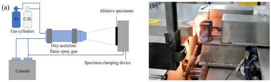
Figure 2.
Ablation platform: (a) schematic diagram of ablation platform; (b) local diagram of the ablation platform.
Before and after the test, the mass and thickness of the specimen were measured using an electronic scale and a depth gauge, respectively. Due to the Gaussian distribution of heat from the oxygen–acetylene flame, there was a significant thermal gradient from the center to the edge of the specimen, resulting in uneven ablation across the entire specimen surface. Therefore, the measurement position was standardized. The line ablation rate was measured at the ablation center of the specimen and the mass ablation rate was measured on the entire ablated specimen. The line ablation rate (LAR) and mass ablation rate (MAR) can be expressed as follows [30]:
where and are the thicknesses of the specimen center before and after ablation, and are the masses of the specimen before and after ablation, respectively, and t is the ablation time.
The microstructure of the specimens after ablation was analyzed using a field emission electron scanning microscope (FESEM; Gemini SEM 500, ZEISS company, Oberkochen, Germany), and elemental and physical phase analyses were carried out using an energy spectrometer (EDS) and X-ray diffractometer. The macroscopic morphology after ablation was reconstructed using Reeyee 3M (Weibu company, Nanjing, China).
3. Results and Analysis
The essence of ablation is material removal, which is a coupled process involving the external flow field, surface ablation, and internal heat transfer. In this section, the morphology of the ablated specimens is analyzed from both macroscopic and microscopic perspectives. Additionally, the ablation properties of C/SiC and C/SiC-ZrC are examined in conjunction with the macroscopic morphology and ablation parameters. Furthermore, the ablation mechanisms of C/SiC and C/SiC-ZrC are analyzed through observation of the materials’ microscopic morphology using scanning electron microscopy.
3.1. Macro Morphology
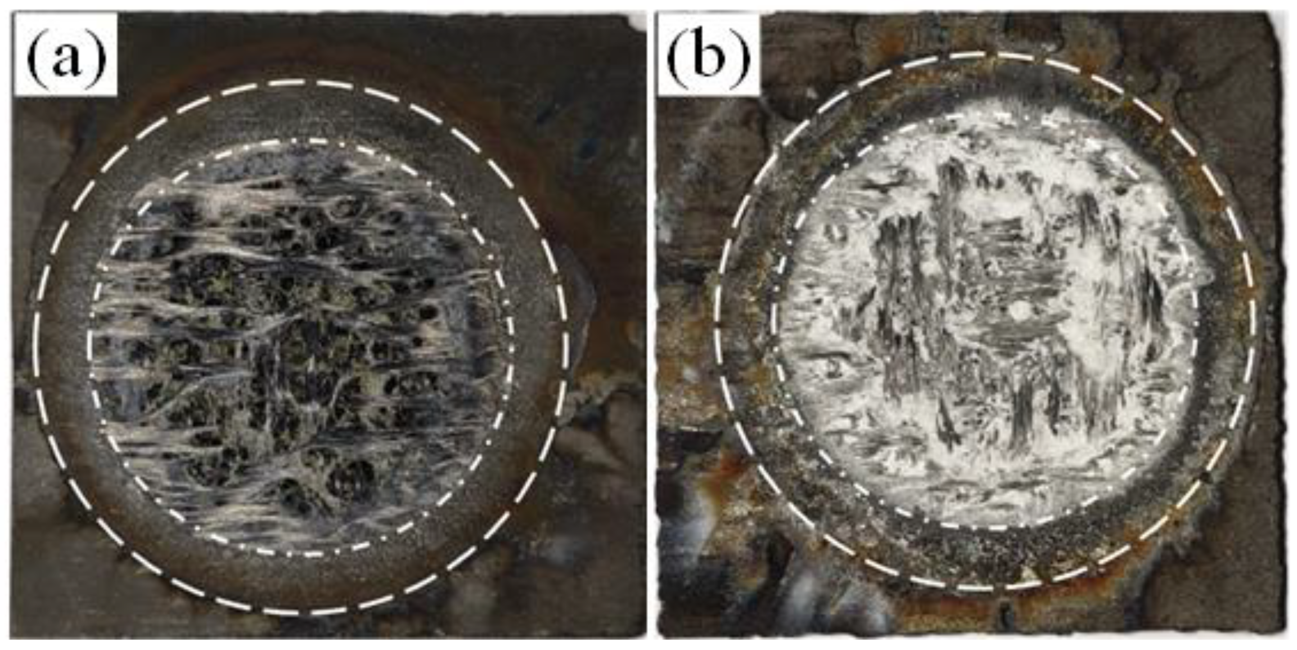
Figure 3 demonstrates the macro-morphology of C/SiC and C/SiC-ZrC after ablation for 30 s. From the figure, it can be seen that the C/SiC ablation area is divided into three areas by two concentric circles: the center area, the transition area, and the edge area. The central ablation area is a smaller pit. The center area is most seriously ablated; the surface is loose and porous, with a large number of oxidized carbon fibers exposed. From a macroscopic perspective, we can see a lot of pores of different sizes, which are formed because the C fibers of the vertically ablated surface were ablated first, before the SiC substrate. Secondly, the transition area is flat and shiny, showing a gray-black ring. The edge area is the farthest from the ablation center, where the temperature and partial pressure of gas are the lowest, and the surface has the lowest degree of ablation. The center area of the C/SiC-ZrC after ablation also shows a smaller pit, indicating that the C/SiC-ZrC was also subject to erosion during the ablation process, with fewer fibers exposed. A layer of grayish-white material covers the center area. The surface of the center area is flatter, and the generated grayish-white substance fills the pores on the surface, hindering oxidative gas erosion, preventing the internal material from being further ablated.

Figure 3.
C/SiC and C/SiC-ZrC ablation specimens: (a) C/SiC macro ablative morphology; (b) C/SiC-ZrC macro ablative morphology.
The ablation morphologies of 3D reconstructed C/SiC and C/SiC-ZrC are shown in Figure 4. The center ablation region, transition region, and edge region can be roughly seen from the 3D morphology. Figure 4a,b show the morphologies of C/SiC after ablation for 30 s and 60 s, respectively, and the distribution of yarns can be seen, with a large number of discontinuous fibers exposed. The depth of the pits increases with the increase in ablation time. Figure 4c,d depict the morphologies of C/SiC-ZrC after ablation for 30 s and 60 s, respectively. Compared with the C/SiC morphology, the central ablation area of the C/SiC-ZrC surface is smaller than that of C/SiC. The yarn distribution is not visible, with fewer exposed fibers, and the ablated surface is flatter. With the increase in ablation time, the depth of the pits also increases. Under the same ablation time, the depth of the pits in C/SiC-ZrC is smaller than that in C/SiC, so the linear ablation rate of C/SiC-ZrC is smaller than that of C/SiC. It can be seen that the ablation resistance of C/SiC-ZrC is better than that of C/SiC.
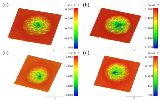
Figure 4.
Reconstruction of 3D topography: (a) C/SiC topography after 30 s of ablation; (b) C/SiC topography after 60 s of ablation; (c) C/SiC-ZrC topography after 30 s of ablation; (d) C/SiC-ZrC topography after 60 s of ablation.
3.2. Ablation Parameters
Table 1 lists the ablation measurements of the C/SiC specimens. The table shows the line ablation rate and mass ablation rate of the ablated C/SiC specimens. The average value of the line ablation rate of C/SiC is 0.03555 mm/s, and the average value of the mass ablation rate is 0.00985 g/s. The deviation of the line ablation rate and the mass ablation rate relative to the average value for 30 s of ablation is 9.42% and 7.61%, respectively. After 60 s of ablation, the deviation decreased by 17.22% for the line ablation rate and increased by 16.48% for the mass ablation rate, relative to the values at 30 s of ablation.

Table 1.
C/SiC ablation rate results.
Table 2 shows the results of the ablation rate test for six C/SiC-ZrC ablation specimens. The average value of the line ablation rate for the six ablation specimens was 0.0249 mm/s, and the average value of the mass ablation rate was 0.01275 g/s. The line ablation rate of C/SiC-ZrC when ablated for 30 s had the maximum value of 0.0356 mm/s, with a deviation of 42.97% from the average value. The line ablation rate and mass ablation rate of C/SiC-ZrC after 90 s of ablation were the lowest values, at 0.0158 mm/s and 0.0019 g/s, respectively.
Table 2.
C/SiC-ZrC ablation rate results.
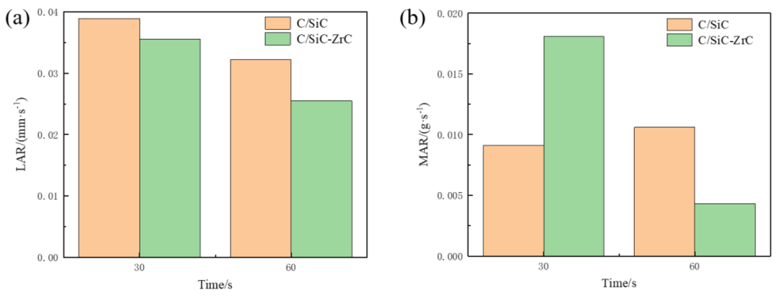
Figure 5 compares the ablation rates of C/SiC and C/SiC-ZrC at 30 s and 60 s. The C/SiC-ZrC line ablation rate was lower than that of C/SiC at both time points. At 30 s and 60 s, the line ablation rate of C/SiC-ZrC was 8.48% and 20.81% lower than that of C/SiC, respectively. From 30 s to 60 s, the line ablation rate of C/SiC-ZrC decreased by 0.0101 mm/s, and the line ablation rate of C/SiC decreased by 0.0067 mm/s. The increase in the pit depth in the ablation center of C/SiC-ZrC material was smaller than that of the C/SiC material, which indicates that the degree of erosion of C/SiC-ZrC material was smaller than that of the C/SiC material at the same time. The mass ablation rate of C/SiC-ZrC was higher than that of C/SiC at 30 s, while the mass ablation rate of C/SiC-ZrC was lower than that of C/SiC at 60 s. The comparison of the two mass ablation rates shows that ZrC had little effect on the ablation rate in the early stages of ablation, and the addition of ZrC slowed down the ablation rate of the composites as the ablation time increased.

Figure 5.
C/SiC and C/SiCZrC ablation rate after 30 s and 60 s of ablation: (a) linear ablation rate; (b) mass ablation rate.
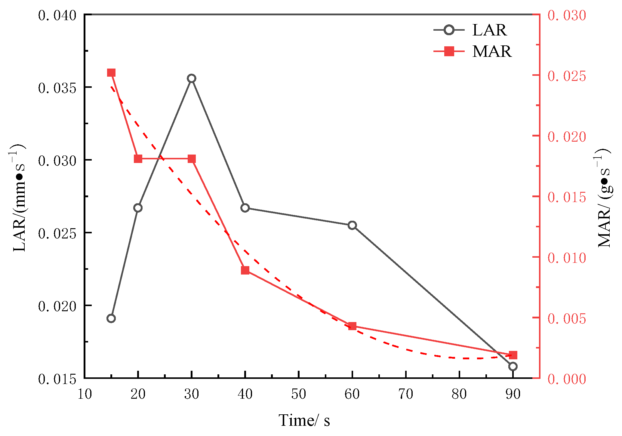
The ablation rate of C/SiC-ZrC over time is shown in Figure 6. The mass ablation rate of C/SiC-ZrC decreased gradually as time increased. From 30 s to 60 s, the mass ablation rate decreased by 76.24%, and from 60 s to 90 s, it decreased by 55.81%. As time passed, the rate of decrease in the mass ablation rate slowed down. The main reason is that at the beginning of the test stage, the material was subjected to ablation and no new product had yet been generated, so the ablation rate of the material was faster. As ablation continued to occur, the generated ZrO2 had a higher density and covered the surface of the material, which prevented the flame from penetrating, resulting in the gradual slowdown of the mass ablation rate. On the other hand, the line ablation rate first increased and then gradually decreased as time increased. This is mainly because at the beginning of the test stage, the temperature had not yet stabilized. After a period of ablation, when the flame temperature stabilized, the product began to be generated in large quantities and covered the surface of the material, causing the line ablation rate to start decreasing. Over the ablation time from 15 s to 90 s, the line ablation rate decreased by 17.28%.

Figure 6.
LAR and MAR of C/SiC-ZrC at different ablation times.
3.3. Microscopic Morphology
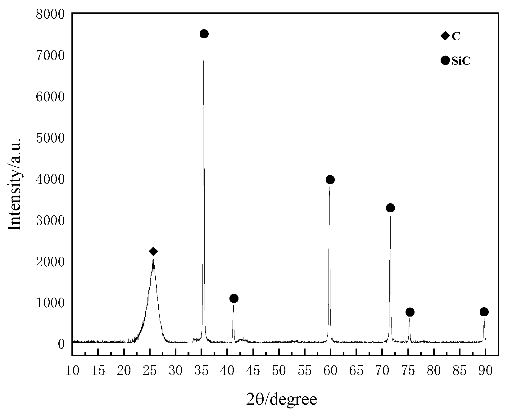
The X-ray diffraction pattern of the ablated surface of the C/SiC is shown in Figure 7. From this, it can be observed that the surface of the C/SiC after ablation consisted of C and SiC, and there is no diffraction peak indicating the presence of a SiO2 material phase. The primary reason is that during the high-temperature ablation process, the surface of the material heated up rapidly, exceeding the boiling point of SiO2 (2230 °C). This led to the direct evaporation and sublimation of SiO2, either due to the high temperature or the reaction with oxidizing gases during the sublimation process, resulting in the formation of volatile SiO. Additionally, the transition region of SiO2 may not be detectable due to its low degree of crystallization [31]. Similarly, the transition zone SiO may not be detected due to the low degree of crystallization.
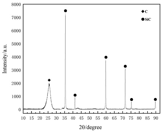
Figure 7.
The XRD pattern of the C/SiC ablative surface.
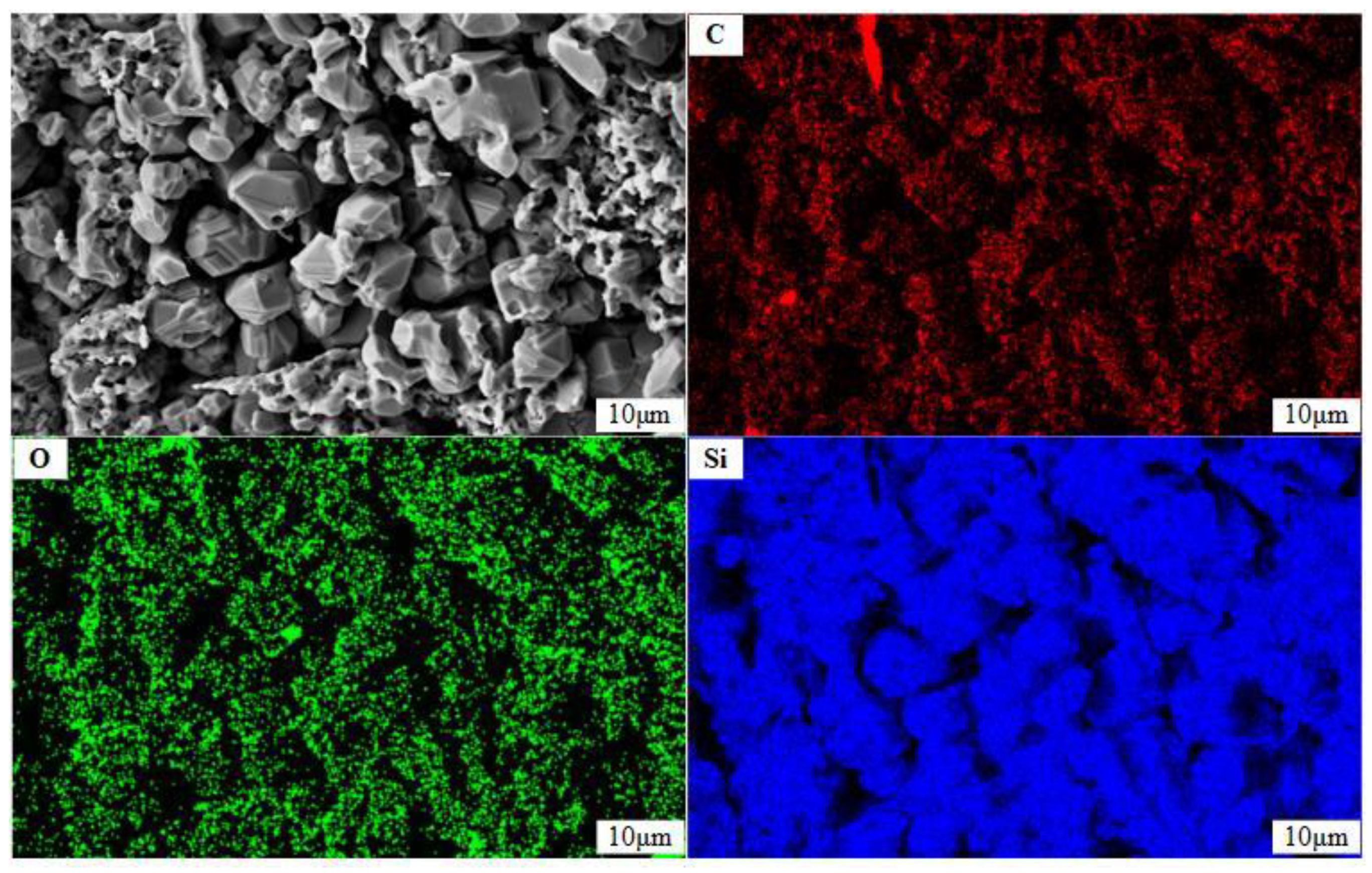
Figure 8 shows the microscopic morphology of the C/SiC material matrix after ablation. After ablation, the C/SiC matrix exhibited a granular shape, broken into an irregular organization. EDS analysis was conducted on the matrix portion of the ablation center to detect the elements present. The instrumental results indicate that the matrix was covered with C, O, and Si elements, with a more uniform distribution of oxygen elements. This suggests the formation of a silicon–oxygen compound on the surface.
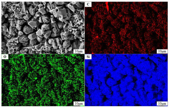
Figure 8.
The EDS diagram of the matrix after C/SiC ablation.
The equilibrium composition of oxyacetylene combustion products was calculated according to the Chemical Equilibrium with Applications Code from NASA, which is a program to calculate chemical thermodynamic equilibrium compositions by the principle of free energy minimum [32,33]. The gas composition and combustion products of the oxygen–acetylene flame are presented in Table 3 [34]. It can be observed that O2, CO2, and CO are the primary components of the oxygen–acetylene flame. During the ablation process, the specimens primarily underwent chemical reactions with these three components. Mainly, the C fiber and SiC matrix were oxidized, resulting in the production of CO, CO2, SiO, SiO2, etc. The reactions that may occur in C/SiC materials are shown in Table 4.
Table 3.
Oxygen–acetylene flame composition and combustion products [34].
Table 4.
The chemical reactions that may occur during the thermochemical reaction of C/SiC [35,36,37].
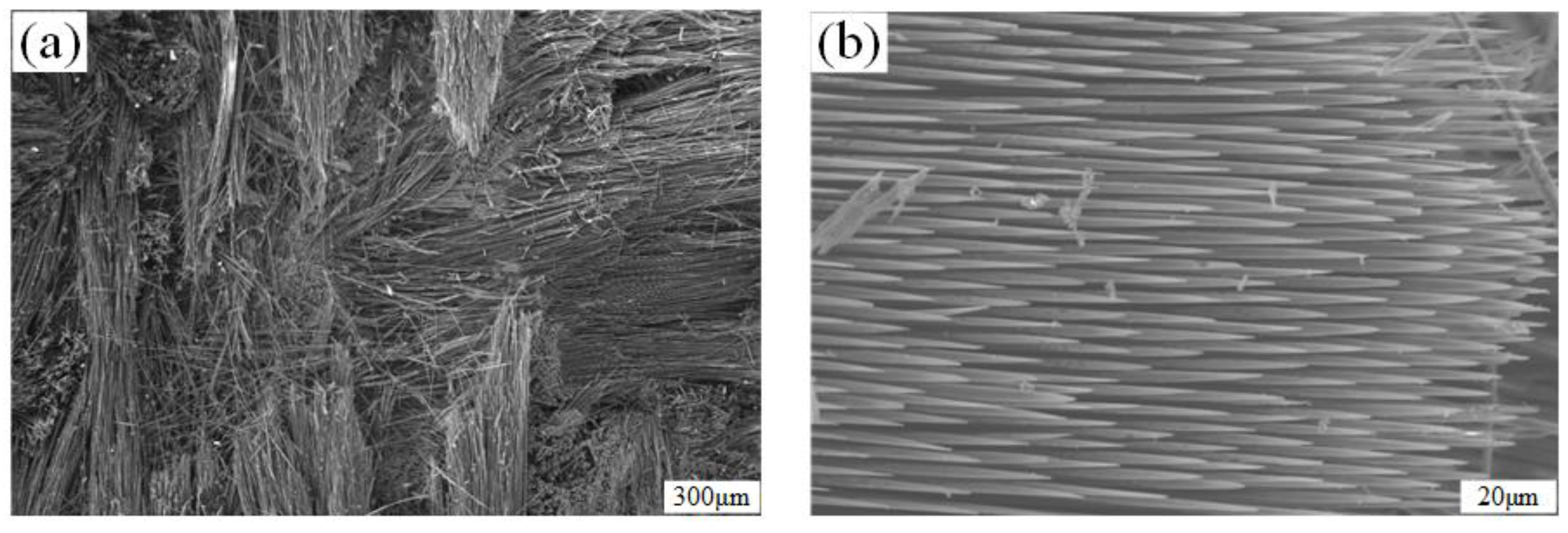
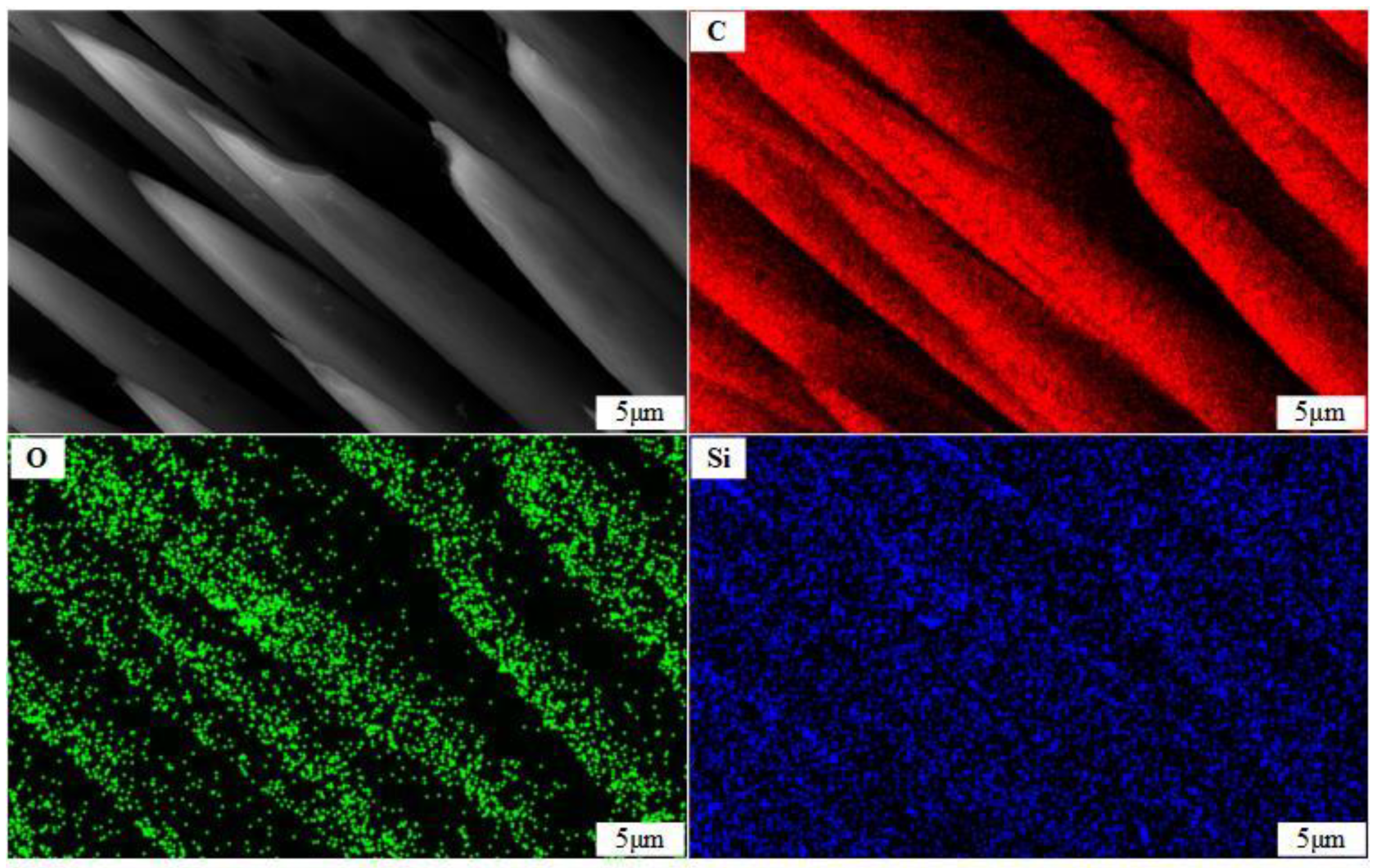
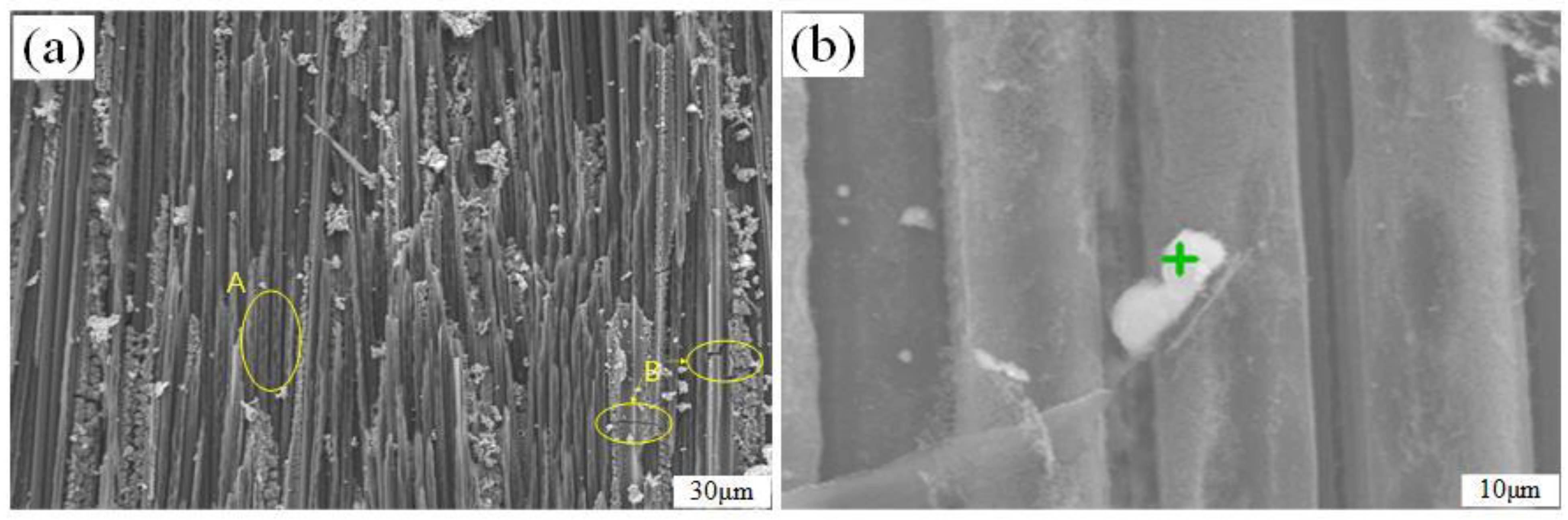
In the high-temperature ablation process, the center temperature of the oxygen–acetylene flame can reach up to 3000 °C, while the sublimation temperature of the SiC substrate is 2700 °C. The sublimation temperature of carbon fiber is approximately 3100 °C, which is significantly higher than that of the SiC substrate. Meanwhile, the latent heat of sublimation of SiC is 19.825 MJ/kg, and the latent heat of sublimation of carbon fiber is 59.75 MJ/kg. Given these factors, the ablation rate of the SiC matrix is higher than that of carbon fiber, hence the ablation resistance of carbon fiber is superior to that of the SiC matrix. As shown in Figure 9, under high temperatures and high-speed airflow, the matrix near the fiber has been completely burned and consumed, leaving only the fiber directly exposed to the air. The fiber is fractured by the high-speed airflow. At the end of the fractured fiber, the temperature is highest. Carbon fiber has good thermal conductivity, so the heat rapidly transfers along the fiber’s longitudinal direction, causing the erosion area to continue expanding. Furthermore, it is easy for a gas vortex to form between the carbon fiber and SiC substrate. This vortex heats the aggregation, accelerating the ablation of both the substrate and the fiber. As the ablation time increases, the front end of the carbon fiber becomes thinner and thinner, while the back end remains relatively thicker, resulting in an overall needle-like shape [37]. Figure 10 is the EDS diagram of the carbon fiber. The fiber surface is uniformly distributed with three elements: C, O, and Si. The content of the C element accounts for 94.86%, the O element for 1.72%, and the Si element for 0.20%. This indicates that there is a very small amount of SiO2 adhering to the fiber surface. In the center ablation zone, the ablation mechanism is primarily dominated by sublimation and mechanical stripping.
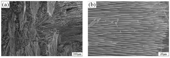
Figure 9.
The SEM diagram after C/SiC fiber ablation: (a) ablation center; (b) ablation fibers.

Figure 10.
The EDS diagram of fibers after C/SiC ablation.
The C/SiC-ZrC specimens also underwent chemical reactions during the ablation process, and Table 5 lists the possible reactions of the C/SiC-ZrC material, in addition to the potential chemical reactions of the C/SiC material. Detailed observation of the surface of the C/SiC-ZrC composite material revealed a distinct difference between its micro-morphology and that of the C/SiC after ablation. Figure 11 shows the XRD pattern of the ablated surface of C/SiC-ZrC, from which it can be seen that the compounds detectable on the surface of the C/SiC-ZrC material after ablation at nearly 3000 °C were ZrO2, SiC, SiO2, and ZrC. The ZrO2 peaks are particularly prominent, indicating a higher content of ZrO2.
Table 5.
Possible reactions of C/SiC-ZrC composites [38].
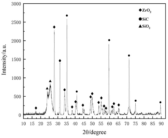
Figure 11.
The XRD pattern of the C/SiC-ZrC ablative surface.
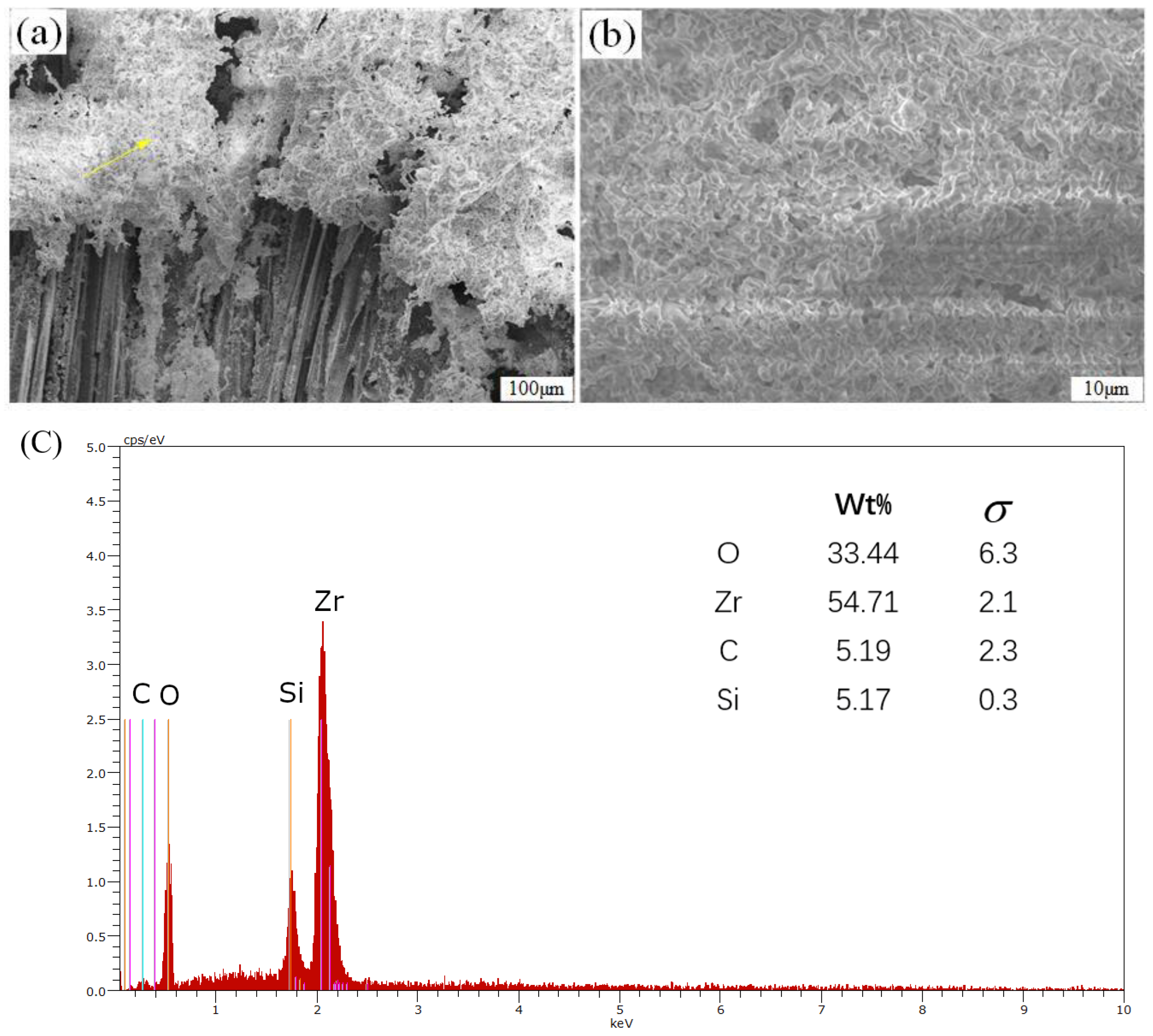
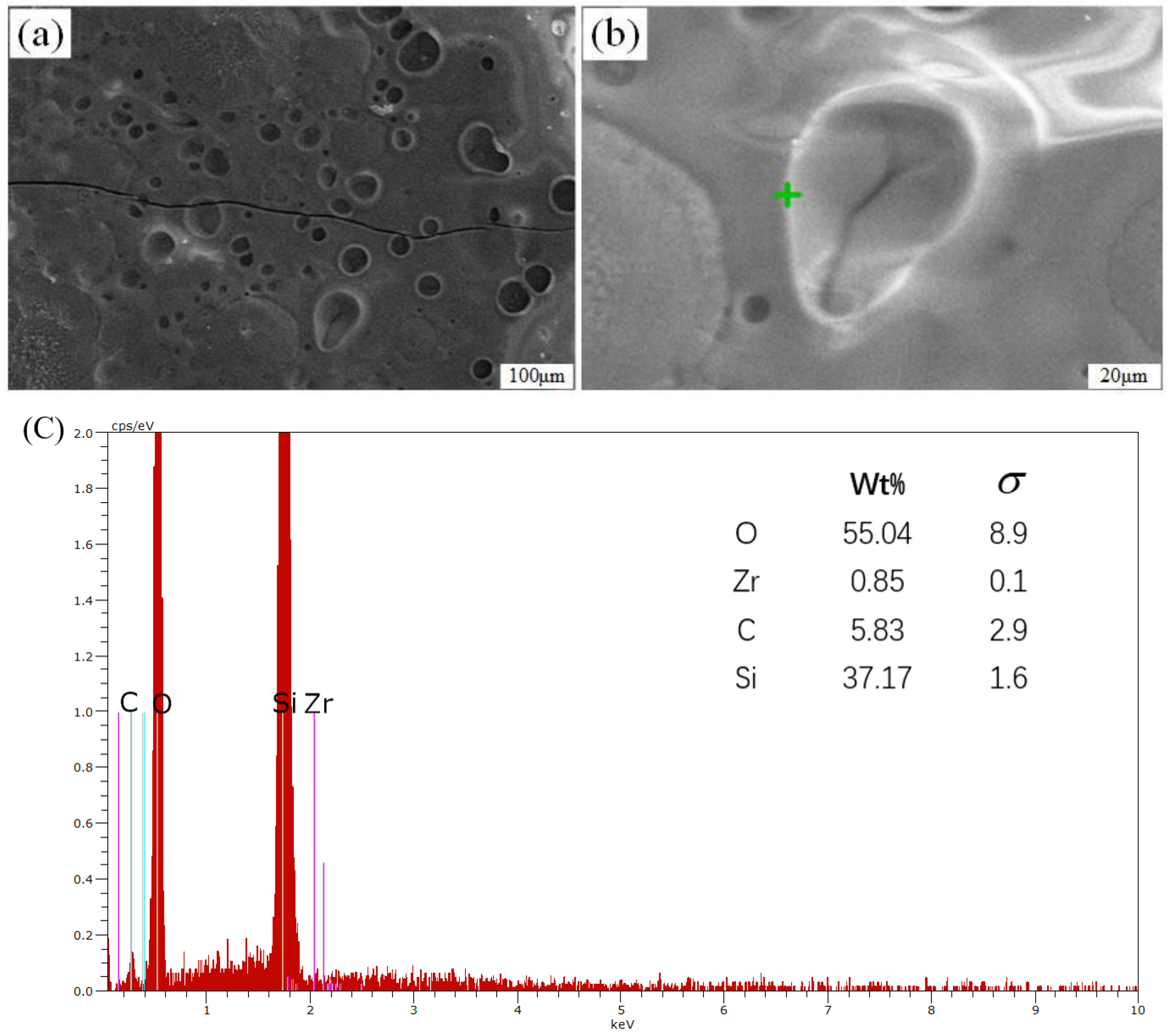
Figure 12 shows the micrograph of the ablation center of C/SiC-ZrC. In Figure 12a,b, a large amount of white flocculent material (Shown by the yellow arrow) can be seen covering the surface of the fiber. Upon magnification, Figure 12c reveals that through observation and energy spectrum analysis, it can be concluded that the white flocculent material mainly contains four elements: Zr, O, C, and Si. Of these, Zr and O elements account for up to 88.15%. Combined with the EDS spectrum, it can be determined that the white material is primarily ZrO2. The oxygen–acetylene flame temperature was 3000 °C, and at this temperature the molten ZrO2 forms a viscous ZrO2-SiO2 melt layer with SiO2 [39,40]. The ZrO2-SiO2 melt layer has a high viscosity and covers the surface of the material to protect it.
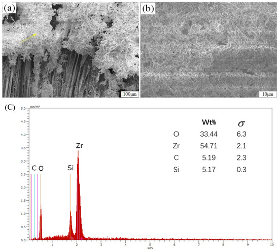
Figure 12.
Microscopic diagram of the C/SiC-ZrC ablation center: (a) surface; (b) white flocculent; (c) EDS diagram of surface.
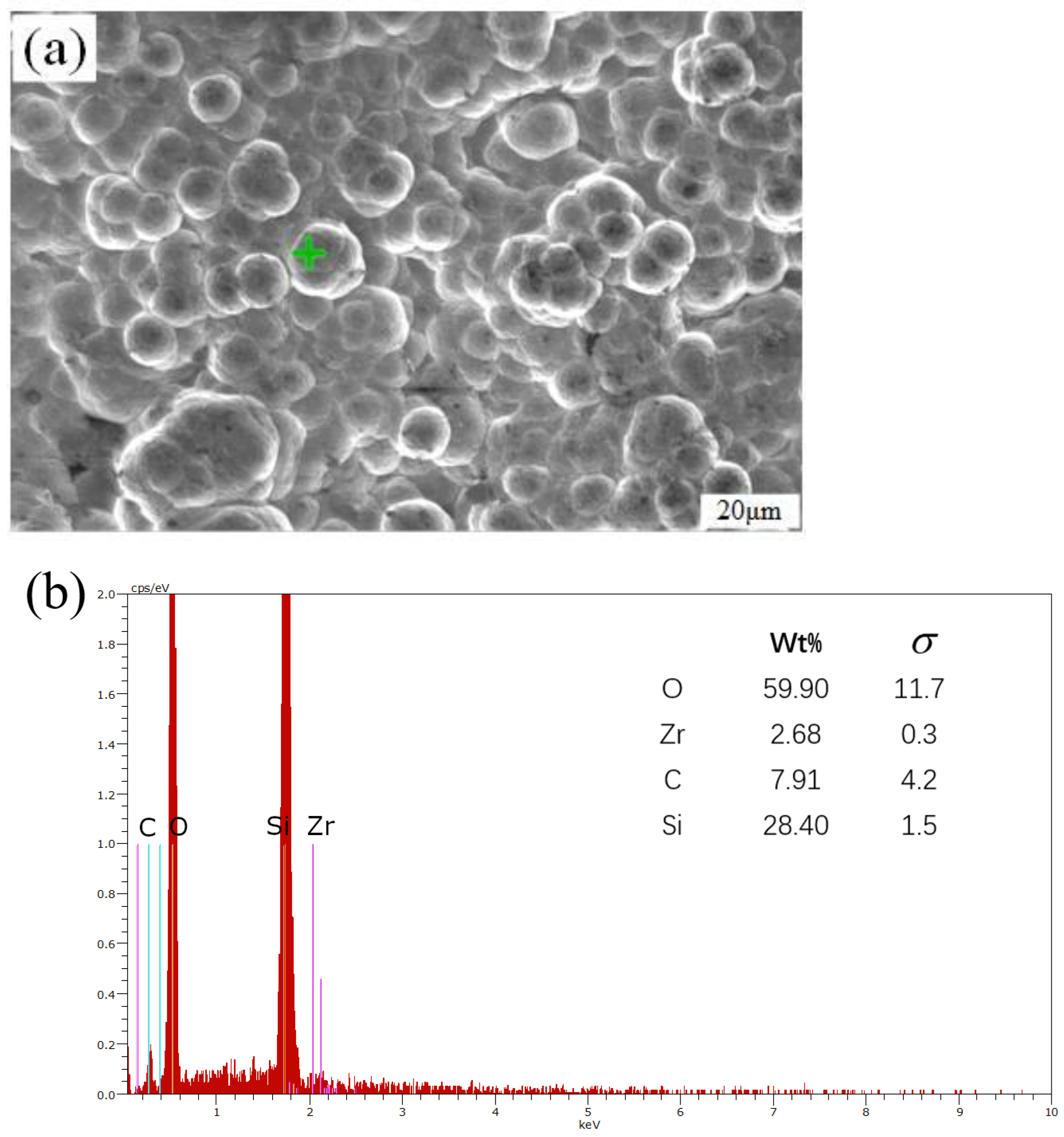
The fibers not covered by ZrO2 oxide are exposed on the surface, as shown in Figure 13a. Fibers parallel to the surface have been partially broken under the action of the high-speed air flow and have left erosion traces. As shown in area A of Figure 13a, the fibers are no longer intact and cylindrical. The broken fiber area has spikes, and there are particles of different sizes attached to the surface. As shown in area B of Figure 13a, accompanied by the uneven distribution of thermal stress during the heating process of high-temperature airflow, cracks appeared on the fiber surface. Figure 13b is a magnified image of the fiber surface, and it can be clearly seen that the fiber surface is no longer cylindrical. Analysis of the energy spectrum through the position of the green symbol of Figure 13b, the proportion of Si, Zr, and O in the white substance attached to the fiber was found to be 45.59%, in which the content of Si is higher than that of Zr. The white substance is a mixture of SiO2 and ZrO2. The SiO2 oxidized by SiC has a low viscosity and is easily dispersed by the high-speed airflow, forming small agglomerates. Figure 13d is a scanning electron microscope image of fibers perpendicular to the surface. The fiber bundles of yellow circle in Figure 13dare needle-punched carbon fibers with sharp or obtuse shapes at the fiber ends, and it can be seen that the oxyacetylene flame has thermo-mechanically stripped the fibers perpendicular to the surface.
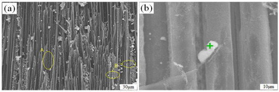
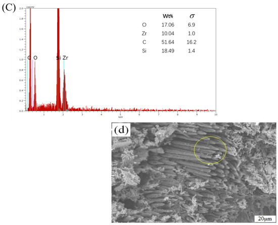
Figure 13.
Micromorphology of C/SiC-ZrC fibers after high-speed airflow scouring: (a) fibers with parallel surfaces; (b) localized fiber surface; (c) EDS diagram of fiber surface; (d) fibers perpendicular to the surface.
Figure 14 shows the micro-morphology of the transition region, and Figure 14a displays the morphology of the substrate in the transition region. It can be observed that cracks have appeared on the surface of the substrate, which were caused by thermal stress resulting from the mismatch of thermal expansion coefficients between the substrate and the surface oxide layer during the cooling process. At the same time, there are numerous bubbles and pits on the surface of the substrate. The gases inside the bubbles were CO and SiO, produced during the ablation process. Under high pressure, the pressure difference between the inside and outside of the bubbles exceeded the surface tension, which led to the rupture of the bubbles and the escape of the gases to form pits. The pits were partially filled by silica in the fused state but did not finish filling. Figure 14c shows the EDS analysis of the green symbol in Figure 14b, which shows that the content of Zr elements is very low, while the content of O and Si elements is 92.21%. This indicates that the surface of the ablation transition zone is dominated by silica, mainly due to the flow of silica on the surface formed by oxidation of the silicon carbide substrate at high temperatures, and the ZrC in the coating has not melted but is covered by the fused silica.

Figure 14.
Microscopic diagram of the transition zone of C/SiC-ZrC ablation surface: (a) morphology of the substrate; (b) bubbles; (c) EDS diagram of the edge of a bubble.
The ablation edge region is the furthest region from the flame center, which is subjected to the lowest temperature and surface pressure, and therefore experiences the lowest degree of ablation. Figure 15a displays the micro-morphology of the matrix in the edge region after ablation. Figure 15b shows the EDS analysis of the green symbol in Figure 15a, it is evident that the matrix in the edge region is abundant with particles and exhibits fewer ablation traces from the high-temperature gas flow. According to the EDS energy spectrum, the SiO2 present in the matrix of the edge region is partially due to the oxidation of SiC.
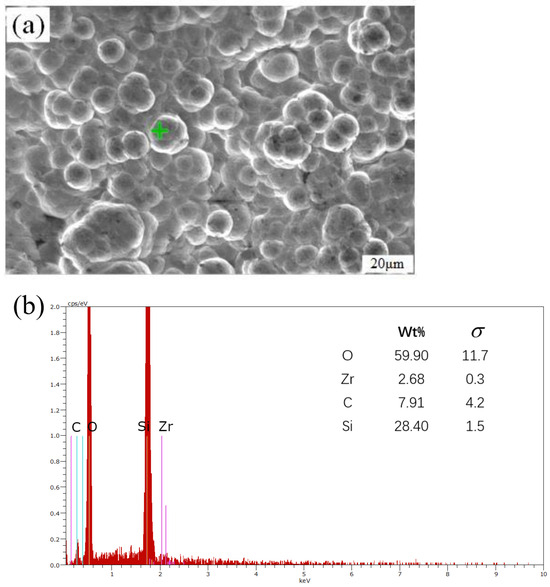
Figure 15.
Microscopic diagram of the edge zone of the C/SiC-ZrC ablation surface: (a) micromorphology of the matrix in the edge region; (b) EDS diagram of the edge.
The macroscopic and microscopic morphologies resulting from ablation are interconnected, and the three regions of macroscopic morphology exhibit different microscopic morphologies. In the ablation center area of the macroscopic morphology, the temperature is the highest and the partial pressure of oxygen is large. Under high-speed gas flow, the fibers exhibit a needle-like appearance, with ZrO2 covering the surface. Secondly, in the ablation transition zone, the degree of ablation is reduced and ZrO2 and SiO2 substances can be detected microscopically. Additionally, there are pits and bubbles on the surface of the material. Finally, in the ablation edge zone, the material is least affected, primarily due to the high-temperature oxidation of SiC.
3.4. Ablation Mechanism
SiO2 has a melting point of 1723 °C, and ZrO2 has a melting point of 2750 °C [41]. The surface temperature of C/SiC material increased gradually with the increase in ablation time, and the temperature reached the melting point of SiO2 first. The solid SiO2 generated by oxidation on the surface of the material started to change into a liquid phase, but the viscosity of the molten SiO2 being small, part of the liquid SiO2 was washed away under the action of high-speed airflow (as shown in Figure 3a and Figure 9a). This resulted in part of the internal material being exposed to the air, and the high-temperature airflow continued to erode the internal material. The possible reactions in this process are shown in Table 4. The high-temperature airflow continued to erode the interior of the material, and the reactions that may occur during this process are also detailed in Table 4. The C/SiC-ZrC material not only generated SiO2 but also ZrO2 during the ablation process. Table 5 outlines the possible chemical reactions that may occur in C/SiC-ZrC, based on the chemical reactions of the C/SiC material. The generated ZrO2 has a higher melting point, higher density (5.89 g/cm3), and higher viscosity in the molten state (as shown in Figure 3b and Figure 12a), enabling it to withstand high-temperature ablation with minimal evaporation and loss. It adheres to the surface of the material, filling in crevices and voids, and isolating the material from the flame, thus reducing further gas intrusion. Simultaneously, ZrO2 can absorb a significant amount of heat during the melting process, lowering the surface temperature of the material and hindering continued erosion of the fibers and matrix caused by the high-temperature gas flow.
4. Conclusions
The ablation tests on the C/SiC material were conducted at 30 s and 60 s, while the ablation tests on the C/SiC-ZrC material were performed at 15 s, 20 s, 30 s, 40 s, 60 s, and 90 s. Additionally, 3D reconstruction of the ablated surfaces of both C/SiC and C/SiC-ZrC materials was carried out for ablation durations of 30 s and 60 s, respectively. This allowed the restoration of the macroscopic morphology of the two materials under different ablation times. The ablation rates of both materials at various time points were compared and analyzed, and the micro-morphology and ablation laws of the materials were explored. Based on these findings, the following conclusions were drawn:
- (1)
- Both C/SiC material and C/SiC-ZrC material form three regions on their surfaces after ablation at high temperature: the ablation center region, the ablation transition region, and the ablation edge region.
- (2)
- At 30 s and 60 s, the line ablation rate of C/SiC-ZrC was 8.48% and 20.81% lower than that of C/SiC, respectively. At the same ablation time, the depth of the crater caused by the erosion of C/SiC material by high-temperature airflow was shallower than that of C/SiC-ZrC, and the bare area was smaller, which shows that the C/SiC-ZrC material is more ablation-resistant than the C/SiC material. C/SiC-ZrC has better application prospects for hot-end components of hypersonic vehicles.
- (3)
- The mass ablation rate of the C/SiC-ZrC material decreased gradually with the increase in time, while the line ablation rate initially increased rapidly and then decreased continuously. With the increase in ablation time from 30 s to 90 s, the line ablation rate and mass ablation rate decreased by 55.62% and 89.5%, respectively. This indicates that the oxides produced by initial ablation oxidation adhering to the surface of the material had the effect of slowing down the ablation rate.
- (4)
- The SiO2 generated by the ablation of C/SiC material is less viscous and is easily blown away by the high-speed airflow, which limits its ability to protect the material. On the other hand, when C/SiC-ZrC material is exposed to high temperature and high-speed airflow, a ZrO2-SiO2 melt layer, dominated by ZrO2, is formed on the surface of the material. This layer is more viscous and denser, covering the surface of the material and filling in surface pores. This effectively slows down the invasion of oxidizing gases and enhances the material’s ability to resist ablation.
Author Contributions
Conceptualization, H.G. and L.Z.; methodology, H.G. and F.F.; software, F.F. and J.D.; validation, F.F. and T.H.; writing—original draft preparation, H.G. and F.F.; writing—review and editing, H.G. and L.Z.; visualization, L.Z.; supervision, X.G.; project administration, X.G. and Y.S.; funding acquisition, Y.S. All authors have read and agreed to the published version of the manuscript.
Funding
This research was funded by the National Science and Technology Major Project, grant number Y2019-I-0018-0017.
Institutional Review Board Statement
Not applicable.
Informed Consent Statement
Not applicable.
Data Availability Statement
The data that support the findings of this study are available from the corresponding author upon reasonable request.
Acknowledgments
We acknowledge the State Key Laboratory of Mechanics and Control for Aerospace Structures and the Key Laboratory of Aero-engine Thermal Environment and Structure, Ministry of Industry and Information Technology for providing research facilities for this work. The authors also wish to thank Zhang Sheng and Wu Tao for their assistance in interpreting the significance of the results of this study.
Conflicts of Interest
The authors declare no conflicts of interest.
References
- Jiang, Z. Standing oblique detonation for hypersonic propulsion: A review. Prog. Aerosp. Sci. 2023, 143, 100955. [Google Scholar] [CrossRef]
- Anand, V.; Gutmark, E.J. Rotating Detonations and Spinning Detonations: Similarities and Differences. AIAA J. 2018, 56, 1717–1722. [Google Scholar] [CrossRef]
- Wang, Y.; Cheng, K.; Dang, C.; Wang, C.; Qin, J.; Huang, H. Performance and experimental investigation for a novel heat storage based thermoelectric harvester for hypersonic vehicles. Energy 2023, 263, 125885. [Google Scholar] [CrossRef]
- Lv, C.; Lan, Z.; Ma, T.; Chang, J.; Yu, D. Hypersonic vehicle terminal velocity improvement considering ramjet safety boundary constraint. Aerosp. Sci. Technol. 2024, 144, 108804. [Google Scholar] [CrossRef]
- Jing, T.; Xin, Y.; Zhang, L.; Sun, X.; He, C.; Wang, J.; Qin, F. Application of Carbon Fiber-Reinforced Ceramic Composites in Active Thermal Protection of Advanced Propulsion Systems: A Review. Chem. Rec. 2023, 23, e202300022. [Google Scholar] [CrossRef]
- Diao, Q.; Zou, H.; Ren, X.; Wang, C.; Wang, Y.; Li, H.; Sui, T.; Lin, B.; Yan, S. A focused review on the tribological behavior of C/SiC composites: Present status and future prospects. J. Eur. Ceram. Soc. 2023, 43, 3875–3904. [Google Scholar] [CrossRef]
- Cheng, L.; Xu, Y.; Zhang, L.; Gao, R. Effect of glass sealing on the oxidation behavior of three dimensional C/SiC composites in air. Carbon 2001, 39, 1127–1133. [Google Scholar] [CrossRef]
- Wang, K.; Xu, C.; Gao, B.; Dai, X.; Deng, T.; Meng, S. Effect of oxidation time on fracture behavior of C/SiC composites at 800 °C in air. J. Eur. Ceram. Soc. 2024, 44, 2078–2086. [Google Scholar] [CrossRef]
- Fang, G.; Ren, J.; Shi, J.; Gao, X.; Song, Y. Thermal Stress Analysis of Environmental Barrier Coatings Considering Interfacial Roughness. Coatings 2020, 10, 947. [Google Scholar] [CrossRef]
- Krenkel, W. C/C-SIC composites for hot structures and advanced friction systems. In Ceramic Engineering and Science Proceedings; John Wiley & Sons, Inc.: Hoboken, NJ, USA, 2003; Volume 24. [Google Scholar]
- Kumar, S.; Chandra, R.; Kumar, A.; Prasad, N.E.; Manocha, L.M. C/SiC composites for propulsion application. Compos. Nanostructures 2015, 7, 225–230. [Google Scholar]
- Breede, F.; Hofmann, S.; Jain, N.; Jemmali, R. Design, manufacture, and characterization of a carbon fiber-reinforced silicon carbide nozzle extension. Int. J. Appl. Ceram. Technol. 2016, 13, 3–16. [Google Scholar] [CrossRef]
- Sun, G.; Li, H.; Yao, D.; Li, H.; Yu, P.; Xie, J.; Pan, X.; Fan, J.; Wang, W. A Multilayer SiC/ZrB2/SiC Ablation Resistance Coating for Carbon/Carbon Composites. Adv. Eng. Mater. 2019, 21, 1800774. [Google Scholar] [CrossRef]
- Zhang, H.; Liu, L.; Feng, W.; Guo, Y.; Han, Q.; Tang, C.; Wang, X.; Xie, Y. Effect of Al addition on the single and cyclic ablation properties of C/C–SiC composites. Ceram. Int. 2023, 49, 6262–6269. [Google Scholar] [CrossRef]
- Du, J.; Yu, G.; Zhang, H.; Jia, Y.; Chen, R.; Liu, C.; Gao, X.; Wang, F.; Song, Y. Microstructural evolution mechanism of plain-woven SiC/SiC during thermal ablation. Corros. Sci. 2022, 208, 110679. [Google Scholar] [CrossRef]
- Fan, X.; Dang, X.; Ma, Y.; Yin, X.; Zhang, L.; Cheng, L. Microstructure, mechanical and ablation behaviour of C/SiC–Si with different preforms. Ceram. Int. 2019, 45, 23104–23110. [Google Scholar] [CrossRef]
- Guo, M.; Cui, Y.; Wang, C.; Jiao, J.; Bi, X.; Tao, C. Characterization and Control of Residual Stress in Plasma-Sprayed Silicon Coatings on SiC/SiC Composites. Coatings 2023, 13, 674. [Google Scholar] [CrossRef]
- Chen, Z.; Fang, D.; Miao, Y.; Yan, B. Comparison of morphology and microstructure of ablation center of C/SiC composites by oxy-acetylene torch at 2900 and 3550 °C. Corros. Sci. 2008, 50, 3378–3381. [Google Scholar] [CrossRef]
- Lee, Y.J.; Joo, H.J. Ablation characteristics of carbon fiber reinforced carbon (CFRC) composites in the presence of silicon carbide (SiC) coating. Surf. Coat. Technol. 2004, 180–181, 286–289. [Google Scholar] [CrossRef]
- Xiang, Y.; Li, W.; Wang, S.; Chen, Z.H. Oxidation behavior of oxidation protective coatings for PIP–C/SiC composites at 1500 °C. Ceram. Int. 2012, 38, 9–13. [Google Scholar] [CrossRef]
- Tang, Y.; Yue, M.; Zhang, J.; Li, Y.; Fang, X.; Feng, X. Revealing thermal ablation mechanisms of C/SiC with in situ optical observation and numerical simulation. J. Eur. Ceram. Soc. 2020, 40, 3897–3905. [Google Scholar] [CrossRef]
- Tang, Y.; Yue, M.; Fang, X.; Feng, X. Evolution of surface droplets and flow patterns on C/SiC during thermal ablation. J. Eur. Ceram. Soc. 2019, 39, 3566–3574. [Google Scholar] [CrossRef]
- Yu, G.; Du, J.; Zhao, X.; Xie, C.; Gao, X.; Song, Y.; Wang, F. Morphology and microstructure of SiC/SiC composites ablated by oxyacetylene torch at 1800 °C. J. Eur. Ceram. Soc. 2021, 41, 6894–6904. [Google Scholar] [CrossRef]
- Fang, X.; Liu, F.; Xia, B.; Ou, D.; Feng, X. Formation mechanisms of characteristic structures on the surface of C/SiC composites subjected to thermal ablation. J. Eur. Ceram. Soc. 2016, 36, 451–456. [Google Scholar] [CrossRef]
- Sevastyanov, V.G.; Simonenko, E.P.; Gordeev, A.N.; Simonenko, N.P.; Kolesnikov, A.F.; Papynov, E.K.; Shichalin, O.O.; Avramenko, V.A.; Kuznetsov, N.T. HfB2-SiC (45 vol %) ceramic material: Manufacture and behavior under long-term exposure to dissociated air jet flow. Russ. J. Inorg. Chem. 2014, 59, 1298–1311. [Google Scholar] [CrossRef]
- Simonenko, E.P.; Simonenko, N.P.; Gordeev, A.N.; Kolesnikov, A.F.; Papynov, E.K.; Shichalin, O.O.; Tal’skikh, K.Y.; Gridasova, E.A.; Avramenko, V.A.; Sevastyanov, V.G.; et al. Impact of a supersonic dissociated air flow on the surface of HfB 2–30 vol% SiC UHTC produced by the Sol–Gel method. Russ. J. Inorg. Chem. 2018, 63, 1484–1493. [Google Scholar] [CrossRef]
- Balat, M.J. Determination of the active-to-passive transition in the oxidation of silicon carbide in standard and microwave-excited air. J. Eur. Ceram. Soc. 1996, 16, 55–62. [Google Scholar] [CrossRef]
- Commission of Science, Technology and Industry for National Defense. Ablation Test Method for Ablative Materials: GJB323A—96; Military Standard Publishing House, Commission of Science, Technology and Industry for National Defense: Beijing, China, 1997. (In Chinese) [Google Scholar]
- Du, J.; Yu, G.; Jia, Y.; Ni, Z.; Gao, X.; Song, Y.; Wang, F. Ultra-high temperature ablation behaviour of 2.5D SiC/SiC under an oxy-acetylene torch. Corros. Sci. 2022, 201, 110263. [Google Scholar] [CrossRef]
- Jiao, X.; Tan, Q.; He, Q.; Qing, M.; Wang, Y.; Yin, X. Cyclic ablation behavior of mullite-modified C/C-HfC-SiC composites under an oxyacetylene flame at about 2400 °C. J. Eur. Ceram. Soc. 2023, 43, 4309–4321. [Google Scholar] [CrossRef]
- Kou, S.; Fan, S.; Ma, X.; Ma, Y.; Luan, C.; Ma, J.; Liu, C. Ablation performance of C/HfC-SiC composites with in-situ HfSi2/HfC/SiC multi-phase coatings under 3000 °C oxyacetylene torch. Corros. Sci. 2022, 200, 110218. [Google Scholar] [CrossRef]
- Gordon, S.; McBride, B.J. Computer Program for Calculation of Complex Chemical Equilibrium Compositions and Applications I: Analysis. NASA Reference Publication, NASA Lewis Research Center: Cleveland, OH, USA, 1994; pp. 25–32. [Google Scholar]
- Gordon, S.; McBride, B.J. Computer Program for Calculation of Complex Chemical Equilibrium Compositions and Applications II: User’s Manual and Program Description. NASA Reference Publication, NASA Lewis Research Center: Cleveland, OH, USA, 1996; pp. 65–71. [Google Scholar]
- Shen, X.T.; Li, K.Z.; Li, H.J.; Fu, Q.G.; Li, S.P.; Deng, F. The effect of zirconium carbide on ablation of carbon/carbon composites under an oxyacetylene flame. Corros. Sci. 2011, 53, 105–112. [Google Scholar] [CrossRef]
- Cui, Y.; Li, A.; Li, B.; Ma, X.; Bai, R.; Zhang, W.; Ren, M.; Sun, J. Microstructure and ablation mechanism of C/C–SiC composites. J. Eur. Ceram. Soc. 2014, 34, 171–177. [Google Scholar] [CrossRef]
- Weng, Y.; Yang, X.; Chen, F.; Zhang, X.; Shi, A.; Yan, J.; Huang, Q. Effect of CVI SiC content on ablation and mechanism of C/C-SiC-ZrC-Cu composites. Ceram. Int. 2022, 48, 7937–7950. [Google Scholar] [CrossRef]
- Wang, Y.; Chen, Z.; Yu, S. Ablation behavior and mechanism analysis of C/SiC composites. J. Mater. Res. Technol. 2016, 5, 170–182. [Google Scholar] [CrossRef]
- Wang, S.L.; Li, K.Z.; Li, H.J.; Zhang, Y.L.; Zhang, W.Y. Ablation behavior of CVD-ZrC coating under oxyacetylene torch environment with different heat fluxes. Int. J. Refract. Met. Hard Mater. 2015, 48, 108–114. [Google Scholar] [CrossRef]
- Zhao, Z.; Li, K.; Kou, G.; Li, W. Comparative research on cyclic ablation behavior of C/C-ZrC-SiC and C/C-ZrC composites at temperatures above 2000 °C. Corros. Sci. 2022, 206, 110496. [Google Scholar] [CrossRef]
- Yang, C.; Zeng, C.; Xu, P.; Song, W.; Xie, X.; Liu, B.; Liu, J.; Su, Z.; Huang, Q.; Cheng, H. Ablation behavior and mechanism of SiCnw modified SiC-ZrC coating for graphite under a plasma ablation flame. Corros. Sci. 2023, 222, 111419. [Google Scholar] [CrossRef]
- Wang, R.; Li, N.; Zhang, J.; Liu, B.; Yan, N.; Fu, Q. Ablation behavior of sharp leading-edge C/C-ZrC-SiC composites using 3000 °C oxyacetylene torch. Corros. Sci. 2022, 206, 110551. [Google Scholar] [CrossRef]


Disclaimer/Publisher’s Note: The statements, opinions and data contained in all publications are solely those of the individual author(s) and contributor(s) and not of MDPI and/or the editor(s). MDPI and/or the editor(s) disclaim responsibility for any injury to people or property resulting from any ideas, methods, instructions or products referred to in the content. |
© 2024 by the authors. Licensee MDPI, Basel, Switzerland. This article is an open access article distributed under the terms and conditions of the Creative Commons Attribution (CC BY) license (https://creativecommons.org/licenses/by/4.0/).