Article

Preparation and Properties of Environmentally Friendly, Hydrophobic, Corrosion-Resistant, Multifunctional Composite Coatings

Department of Mechanical Engineering, College of Engineering, Shanghai Ocean University, Shanghai 201306, China
*
Author to whom correspondence should be addressed.
Coatings 2024, 14(5), 586; https://doi.org/10.3390/coatings14050586
Submission received: 11 April 2024 / Revised: 2 May 2024 / Accepted: 6 May 2024 / Published: 8 May 2024
(This article belongs to the Topic Alloys and Composites Corrosion and Mechanical Properties)

Abstract

:
With the continuous exploitation of the marine resources, the equipment should meet the marine complex working environment. In this study, a type of environmentally friendly coating was prepared. Based on low surface energy environmental protection and anti-fouling, a film forming material with water-based epoxy-modified silicone resin emulsion was prepared. And industrial fillers were added to give it both inorganic and organic properties. Meanwhile, various contents of graphene oxide (GO) were added in the coating system. The coating properties were comprehensively analyzed, and the optimal GO content was obtained as 0.1 wt. %. The composite coating was studied by seawater immersion experiments, and the failure process of the coating in was proposed. The composite coating prepared in the present study has both environmental protection and hydrophobic anti-fouling characteristics, and its comprehensive performance is excellent through various performance evaluations, i.e., it meets the requirements of long-term coating, environmental friendliness and anti-fouling and corrosion resistance.

1. Introduction

During the use of aquaculture network facilities, communities derived from the attachment of contaminated organisms to ship hulls make it easy for bacteria and parasites to breed, which will adversely affect the production of aquatic products [1]. A lack of resistance to biological attachment is one of the serious challenges faced by oceanfront equipment. Biological adhesion not only increases the maintenance cost of equipment, but also leads to equipment failure and corrosion failure. Coatings are among the most widely used methods for marine equipment maintenance. Traditional solvent-based antifouling coatings use organic solvents as dispersing media to prevent microbial attachment through the release of sterilizers in the coating system. However, the use of organic solvents consumes a lot of fossil energy, and organic solvents are harmful to the health of construction workers because of their volatility. In addition, the release of sterilizers causes pollution to the marine environment, and is more likely to accumulate in marine organisms, threatening the safety of humans who eat marine organisms. Sun [2] grafted low-toxic structural compounds as sterilization factors onto the side chain of acrylic resin to control the hydrolysis of sterilization factors to achieve self-polishing of the coating. Compared with heavy metal copper sterilization factors they are green, but they are still toxic and still pose a threat to marine microorganisms. In order to solve this industry dilemma, researchers continue to innovate and devote themselves to the development of new materials and new technologies to realize new coatings that are environmentally friendly and anti-fouling.
The birth of the new water-based coating should meet the requirements of being environmentally friendly, such as the advantages of small pollution and low volatile organic matter emissions. However, most of the protective waterborne coatings cannot possess environmental protection, anti-corrosion and anti-adhesion properties at the same time. Water-based epoxy-modified silicone resin emulsions have the properties of both epoxy resin and silicone resin emulsions, high adhesion and low surface energy, thereby meeting the requirements of environmental protection and anti-fouling. The new water-based coating can realize the performance of traditional sol-based coatings and conform to the concept of environmental protection, and it has promising application prospects in the field of anti-corrosion. Through different modification means and technical optimization, the performance of the new water-based coating can be further improved to meet the needs of more practical applications. Xu [3] synthesized a water-based silicone nanocomposite coating with long-term hydrophobicity and self-cleaning performance by combining a silicone emulsion with a TiO2 dispersion by using a mechanical blending method. But its long-term self-cleaning performance was lacking in a natural pollution environment. After mixing the cationic silicone emulsion made by Khanjani [4] with an acrylic emulsion the mixed emulsion was cured at room temperature by using the low glass transition temperature of the acrylic emulsion, and the resulting coating had good hydrophobic and mechanical properties. However, the existence of two emulsions in the coating system required consideration of compatibility and the content of the single components, which was a huge workload.
In order to improve the overall performance of the silicone resin emulsion coating, inorganic fillers were added to the coating system to be more suitable for engineering applications. Wang [5] successfully developed a two-component inorganic coating, and systematically studied the influence of film forming additives on the stability of the coating, and then finally determined the best formula and curing time. Shan [6] used a nanosilica sol as the main film forming material and added an appropriate amount of inorganic filler to prepare an inorganic coating with excellent performance. In recent years, graphene showed great application potential in various fields [7]. It is wise to add it as a filler to water-based resin emulsion with low surface energy to improve the corrosion resistance of coatings. However, because the surface of the emulsion particles is rich in hydroxyl groups, it is easy for them to agglomerate and they have a high activity, which will lead to a reduction in the dispersibility and stability. Tian [8] used ammonium-grafted graphene oxide as a dispersant, which effectively solved the problem of microscopic defects in the preparation of water-based epoxy resin, and improved the compatibility and dispersion of graphene nanoparticles in water-based epoxy resin. Huang [9] significantly improved the cathodic protection and barrier properties of the coating by adding different contents of graphene to the water-based epoxy zinc-containing coating, which benefited from the graphene lamellar barrier effect [10] and conductive effect [11]. Chen [12] introduced graphite (g)-C3N4 into the aqueous epoxy solution by using an ultrasonic dispersion technology, and the modified water-based composite epoxy coating also showed excellent barrier properties. These research studies focus on the uniform distribution of fillers and the improvement of corrosion resistance of coatings, while there are few research studies on low-surface-energy silicone resins.
Based on the above discussions, a simple mechanical stirring method was used to add the inorganic filler to the water-based epoxy-modified silicone resin emulsion, and the crosslinking agent was formed to cure it at room temperature to prepare a stable coating with environmental protection and corrosion resistance. The microstructure, phase change and corrosion resistance of the coating were analyzed by scanning electron microscopy (SEM), X-ray diffraction (XRD) and electrochemical impedance spectroscopy (EIS). The failure mechanism of organosilicone resin was discussed. The addition of the inorganic filler gives the coating both inorganic and organic properties, i.e., more excellent comprehensive properties. The high silicon content of the epoxy-modified silicone resin emulsion gives the coating better hydrophobic properties. In addition, the flake structure of graphene oxide can effectively alleviate the corrosion of a metal matrix. This work provides a new method against microbial attachment and for protection of metal equipment in a marine environment.

2. Methods

2.1. Materials and Reagents

The epoxy-modified silicone resin emulsion (SH9607) was manufactured by Hubei Longsheng Sihai New Materials Co., Ltd. (Shenzhen, China) The array of active additives encompassed dipropylene glycol methyl ether (DPM), sourced from Shenzhen Jinlong Chemical Technology Co., Ltd. (Shenzhen, China); alkynyl glycol 104E, obtained from Air Chemical Products Co., Ltd. (Tokyo, Japan); the water-based dispersible agent SN5040 and the antifoaming agent J0401, both procured from Shenzhen Jitian Chemical Co., Ltd. (Shenzhen, China); and the leveling agent BYK381, purchased from BYK Chemical (Wesel, Germany). As for fillers, single-layer graphene oxide was acquired from Suzhou Carbonfeng Graphene Technology Co., Ltd. (Suzhou, China), talc was sourced from Guilin Guiguang Talc Development Co., Ltd. (Guilin, China), mica powder was obtained from Chuzhou Wansilk New Material Co., Ltd. (Chuzhou, China), iron red was purchased from Henan Bairun New Material Co., Ltd. (Zhengzhou, China), zinc tetrahydrate phosphate was sourced from Sinopdrug Group Chemical Reagent Co., Ltd. (Shanghai, China), and the curing agent KH550 was procured from Dongguan Kangjin New Material Technology Co., Ltd. (Dongguan, China) Q235 served as the substrate for the coating in the conducted experiments, eliminating the need for any further pretreatment.

2.2. Preparation of Different Coatings

The schematic depiction of the composite coating preparation is presented in Figure 1. The Q235 steel plate, measuring 10 mm × 10 mm × 1 mm, underwent polishing using SiC paper graded from 100 to 800, followed by ultrasonic cleaning with absolute ethanol (99.9%) for 10 min. Subsequently, the plate was dried in an air-drying oven maintained at 60 °C. To ensure the effective dispersion of fillers within the coating system, the active additives were initially introduced into the aqueous solvent, and a pretreatment solution was obtained through uniform stirring. High-speed grinding was then employed to incorporate the fillers, resulting in a uniformly colored paste. This colored paste was subsequently combined with the emulsion in a fixed proportion, completing the preparation of the coating. Prior to spraying, the composite coating and curing agent were mixed in a mass ratio of 20:1 and allowed to age for 20 min. The mixture was then sprayed onto the substrate surface and left for curing at room temperature for 7 days, yielding the desired coating with a thickness of approximately 60 ± 5 μm. To investigate the optimal filler dosage, a series of GO-modified composite coatings containing fillers in varying concentrations (0 wt. %, 0.01 wt. %, 0.05 wt. %, 0.1 wt. % and 0.15 wt. %) were prepared and labeled as G0, G1, G5, G10, and G15, respectively.

2.3. Characterization

Optical microscopy and scanning electron microscopy (SEM) (condition: EHT = 3.00 KV, WD = 7.4~8.4 mm) were employed to meticulously observe the morphological features of the modified composite coatings with varying concentrations of GO. Precise measurements of the coating’s water contact angle were conducted using the droplet angle measurement method on a Shanghai Zhongchen JC2000D3-X (Shanghai, China) contact angle/surface tension measuring instrument. Furthermore, X-ray diffraction (XRD) and SEM (condition: EHT = 3 KV, WD = 8.0~8.4 mm) were utilized to comprehensively characterize the microstructural and phase changes in the G10 coating before and after simulated seawater immersion. Ultrasonic thickness gauges (CT400) were utilized to ensure consistent thickness of coatings with different contents. The corrosion resistance of various coatings was rigorously tested in a 3.5 wt. % NaCl solution using an electrochemical workstation (reference 600+). Additionally, the long-term corrosion behavior of the G10 coating was specifically evaluated in simulated seawater. For the electrochemical measurements, a coated steel sample with an exposed area of 1 cm2 served as the working electrode, a saturated calomel electrode was used as the reference electrode, and a platinum plate electrode functioned as the counter electrode. The impedance spectrum measurements were conducted within a frequency range of 100 kHz to 0.1 Hz, with an amplitude of 5 mV. To minimize the influence of external factors, the entire experimental process was conducted within a Faraday cage.

3. Discussion and Results

3.1. Status of Filler

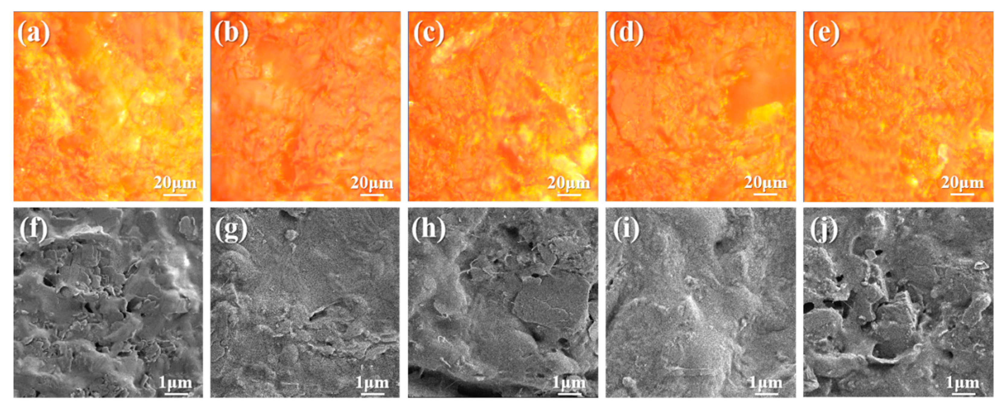
The cross section of the composite coating modified with different contents of GO was polished, and the morphology was observed with an optical microscope to judge the compatibility and the distribution of the GO. As shown in Figure 2a–e, the surface morphology of the coating did not show the state of incompatible fillers, indicating that the fillers were evenly distributed in the composite coating and could be well bonded together by the film-forming material. As shown in Figure 2f–j, cross section micro-morphologies of GO composite coatings with different contents can be seen. The lamellar fillers were detected. The film-forming materials on the surface of the G0 coating (due to its poor electrical conductivity and light color) are obvious, but there are more pores between lamellar fillers. The surface density of the G1 coating is improved. Some of the larger fillers are embedded in the surface of the coating, and the smaller fillers are completely wrapped in the film-forming material. The surface of the G5 coating is similar to that of G1. There is a large flake filler on the surface, and the density of the coating is further improved. There is basically no protruding sheet filler on the surface of the G10 coating, which indicates that the compatibility between the filler and the film-forming material is the best, and the coating is the densest. For the G15 coating surface, more pores are in appearance. Meanwhile the density of the coating is poor, due to too much graphene oxide. It results in the agglomeration in the composite, so that its nanoparticle characteristics begin to gradually fail. The distribution of coating filler is also negatively affected. The higher the density of the coating, the stronger the ability of the coating to block the external medium, the stronger the corrosion resistance. It shows that the appropriate addition of graphene oxide filler is beneficial to improve the overall performance of the coating.

3.2. Hydrophobicity

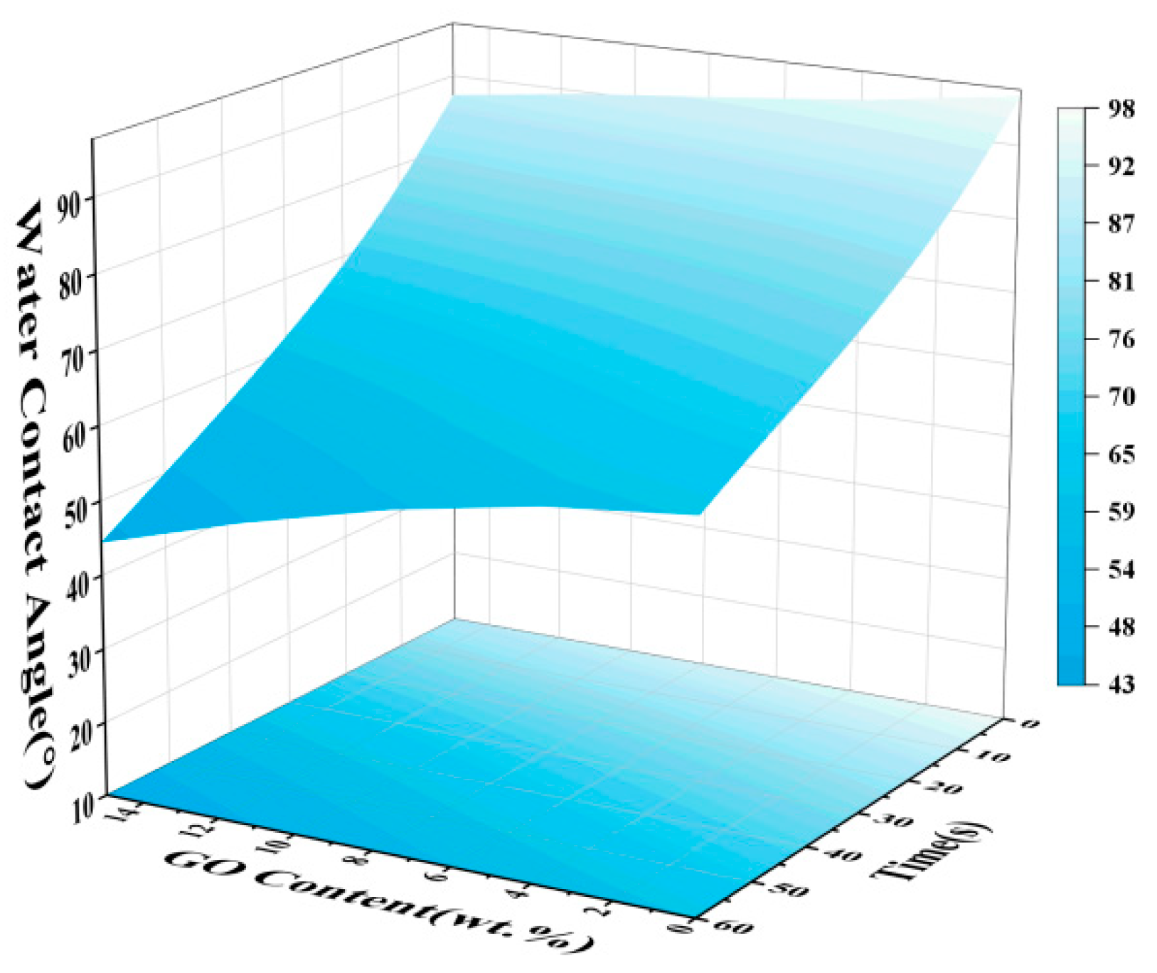
The dynamic water contact angle of the coating can reflect the dynamic anti-fouling performance of the coating. As shown in Figure 3, the dynamic water contact angle changes in composite coatings with different contents of graphene oxide. Because graphene oxide is a hydrophilic nanofiller, the dynamic water contact angle of the coating film shows a decreasing trend with the increase in graphene oxide nanofiller. The reason is that the presence of hydroxyl groups on the edge and base surface of the graphene oxide sheet determines its hydrophilicity. Therefore, with the increase in graphene oxide content in the modified composite coating, the hydrophilicity of the GO was continuously offset by the hydrophobicity of the silicone resin. However, in general, the water contact angle of the composite coating with different graphene oxide contents is greater than 90° at 0 s, and the composite coating has the performance of hydrophobicity at this moment. In the process of a ship traveling, the marine organisms attached to the surface of the ship can be removed by relying on the shear force of the seawater to achieve a better dynamic anti-fouling effect.

3.3. Corrosion Resistance

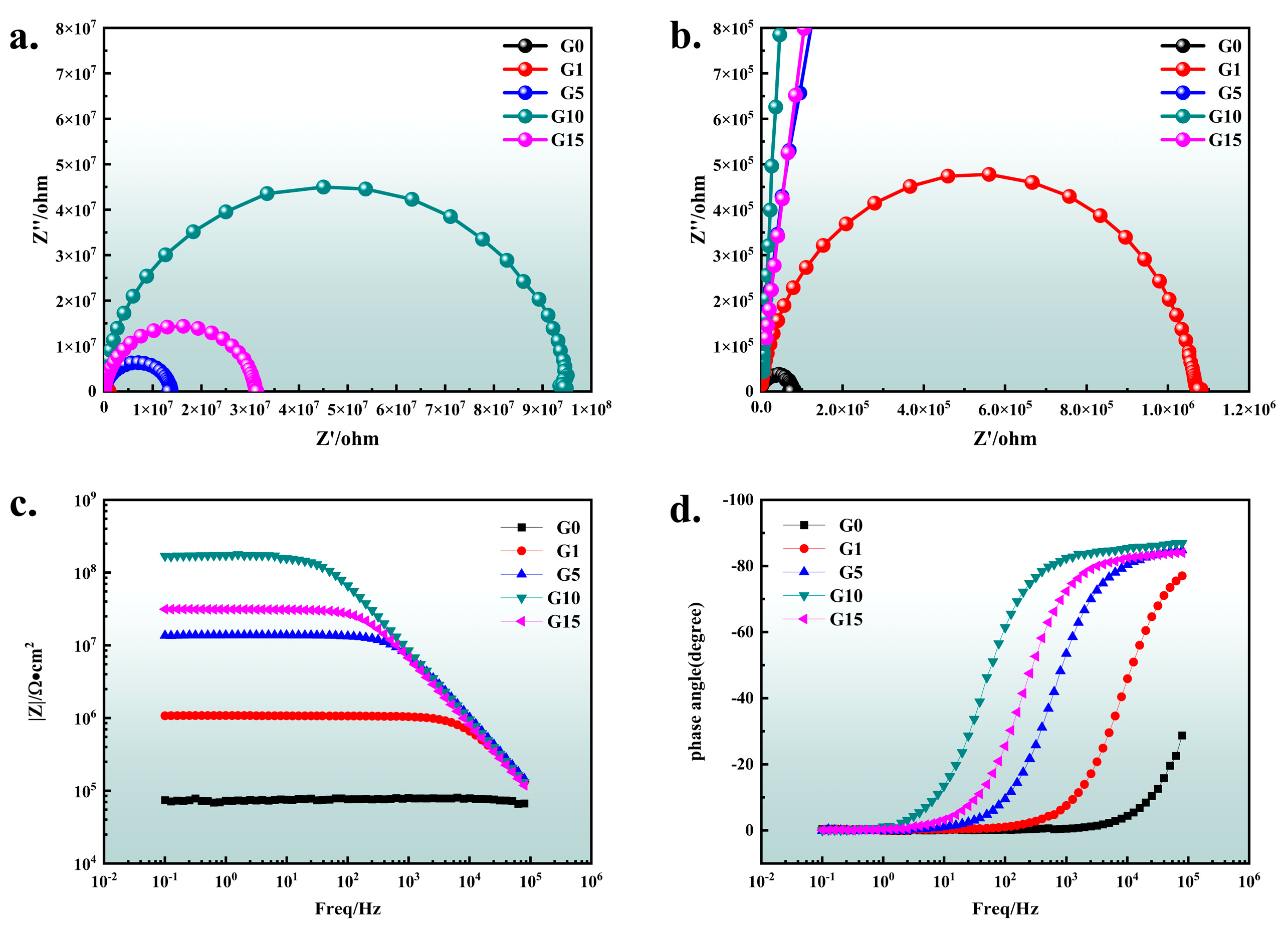
As can be seen from Figure 4a,b, the arc resistance of the composite coating is as follows: G10 > G15 > G5 > G1 > G0, indicating that the corrosion resistance of the composite coating increases first and then decreases with the increase in graphene oxide addition. And G10 has the largest arc resistance radius and the best corrosion resistance. As can be seen from the microscopic morphology of the coating, the number of pores on the surface of the coating gradually decreases with the increase in the content of GO. When the content of GO exceeds 0.1 wt. %, the coating is more easily immersed in the external water, and the corrosion resistance of the coating decreases. As shown in Figure 4c,d, with the increase in graphene oxide content, the impedance mode value |Z| in the Bode figure is as high as 108 and only one time constant appears in the phase angle figure, indicating that the corrosive medium did not penetrate the coating to have an electrochemical reaction with the metal substrate. Compared with the waterborne inorganic zinc-rich coating modified by rGO studied by Jang [13] et al., the coating developed here has better corrosion resistance. It means that the barrier property of the coating is good. With the increase in graphene oxide content, the impedance mode value |Z| in the low-frequency region of the coating firstly increases and then decreases, and the phase angle diagram shifts first to the left and then to the right, which is in accordance with the change rule of the Nyquist diagram. The impedance mode value of the G10 coating is the largest, and the order of magnitude is 108, which is three orders of magnitude larger than that of G0, indicating that the corrosion resistance of the coating can be significantly improved by adding an appropriate amount of graphene oxide to the coating.
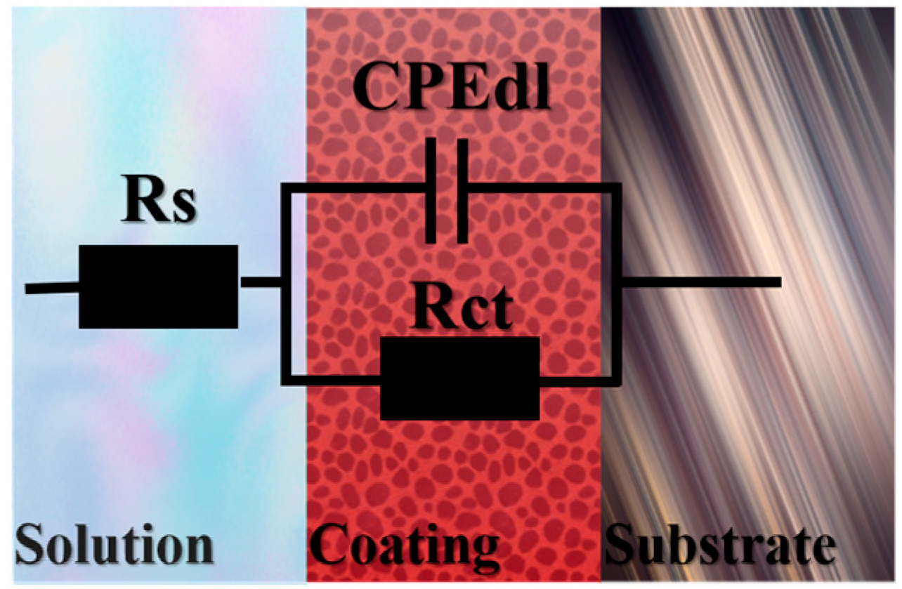
By observing the impedance spectrum of the composite coating, it is found that the coating is a standard charge diffusion. The equivalent circuit diagram of different contents of graphene oxide coating was obtained from the impedance spectrum, as shown in Figure 5. The circuit description code is Rs (CPEdlRct), where Rs is the solution resistance. Rct is the charge transfer resistance, namely the coating resistance. CPEdl is the coating capacitance.
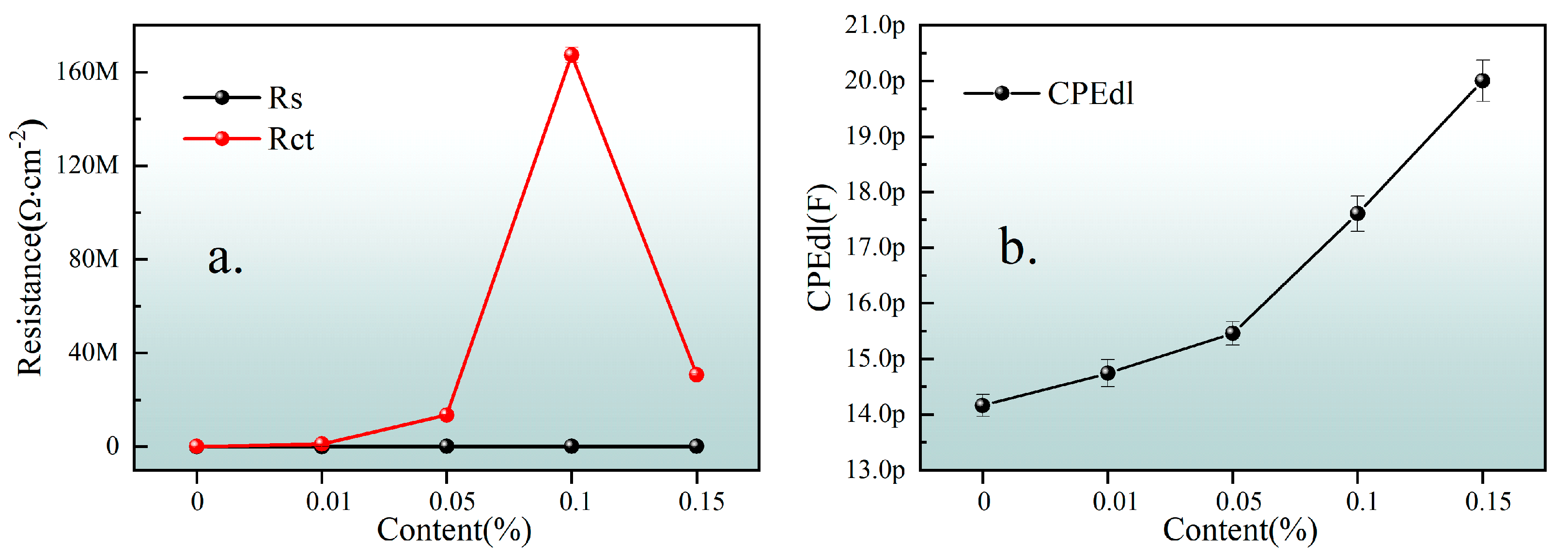
The impedance spectrum was fitted to obtain the equivalent circuit parameter, Table 1, and the equivalent circuit parameter variation, Figure 6. The increasing capacitance of the coating is caused by the increasing pseudocapacitance provided by the oxygen-containing functional groups on the surface of graphene oxide [14]. It can be seen that the coating resistance first increases and then decreases with the content of GO, reaching the maximum value when the content is 0.1 wt. %. Although the sheet graphene oxide has a barrier effect and can delay the penetration of corrosive media, the presence of hydrophilic groups weakens its anti-corrosion performance. Therefore, when a small amount of graphene oxide is added, it is easy to evenly disperse and can effectively play a blocking role. However, with the increase in the addition, the hydrophilicity of the coating is enhanced, resulting in the agglomeration of the graphene oxide, which leads to the decrease in the coating resistance. Therefore, when the amount of GO was 0.15 wt. %, the corrosion resistance began to decrease. The coating capacitance in electrochemical impedance spectroscopy has been proved to be a key parameter to measure the water permeability of the coating [15]. The coating capacitance CPEdl increases with the increase in the graphene oxide content, because CPEdl represents the dielectric property of the coating, and the coating gradually increases during the process of being gradually permeated by electrolytes [16]. The more graphene oxide in the coating, the easier the electrolytes in the coating will penetrate into the coating due to its hydrophilicity, thus increasing the coating capacitance.

3.4. Corrosion Mechanism

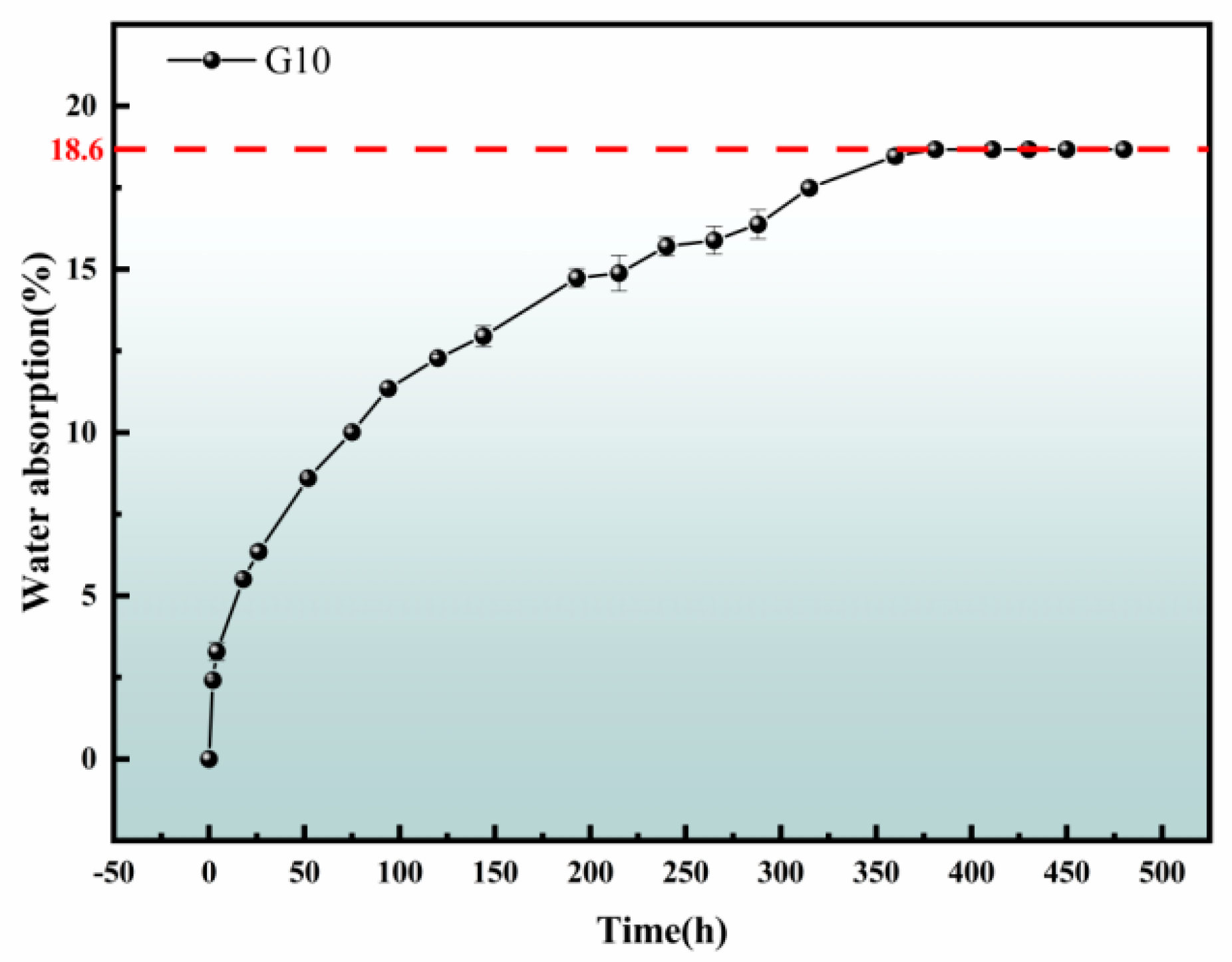
The water absorption of the coating has an important impact on the coating/metal interface, which in turn affects the corrosion resistance of the coating [17]. The corrosion resistance of organic coatings is not only achieved by resistance inhibition, but also by the transport of water and corrosive substances. The low permeability of water does not guarantee the best corrosion resistance, because when osmotic pressure is generated due to surface contaminants, it may cause the coating to blister. On the contrary, a certain osmotic pressure is necessary to prevent blistering. The water absorbed in the coating will affect the coating polymer and cause swelling, which is reflected in the change in dielectric properties [18], so the water absorption rate of the coating can be combined with electrochemistry to jointly analyze them. As shown in Figure 7, the water absorption curve of the composite coating with graphene oxide content of 1 wt. % increases with time. It can be seen that the water absorption rate of the coating film is fast in the initial stage of immersion, and then the water absorption rate gradually slows down until it reaches saturation. When immersed in deionized water for 350 h (≈15 d), the water absorption rate no longer increases, and the water absorption rate at this time is 18.6%.
EIS has been widely used in the study of coating protection and aging mechanisms. The resistance of a coating is an important index to evaluate its corrosion resistance, and the capacitance value can reflect the ability of coating to allow electrolytes to penetrate. In addition, the corrosion rate of the metal under the coating can be understood by estimating the reaction resistance [19]. Generally speaking, the arc radius of capacitive reactance in a Nyquist diagram is inversely proportional to the corrosion rate: the smaller the radius, the faster the corrosion rate of the coating. Conversely, the larger the radius, the slower the corrosion rate [20]. As shown in Figure 8a,b, the arc resistance of the composite coating is semi-circular, indicating that the electrode process is mainly controlled by charge transfer. And the effect caused by impedance is negligible. With the extension of soaking time, the arc radius of the composite coating decreases gradually, and the corrosion resistance weakens gradually. In the simulated corrosion experiment of seawater for 28 days, no second arc resistance appeared, indicating that no corrosion products were formed, which confirmed the excellent corrosion resistance of the composite coating. At the initial stage of immersion, seawater quickly permeates the coating, enhancing the ion conductivity. It results in a sharp decrease in the coating resistance and a significant change in the impedance spectrum. With the extension of soaking time, the penetration rate of seawater slows down, and the change in coating resistance is gradually stable. The change in capacitance–reactance spectrum characteristics decreases. When the soaking time exceeds 350 h, the coating resistance shows a downward trend again, which indicates that corrosion occurs at the interface between the coating and the metal, resulting in local peeling of the coating [21]. As shown in Figure 8c,d, the impedance mode value of the composite coating in seawater, |Z|, gradually decreases with the increase in time, and the phase angle curve gradually shifts to the right with the increase in time, which reflects the continuous decrease in the coating resistance and the gradual decline of corrosion resistance, whose changing speed is consistent with that of the Nyquist diagram.
Combined with the characteristics of the impedance spectrum, structural characteristics and existing studies of the composite coating, the equivalent circuit (which is the same as Figure 5) was used to fit the impedance spectrum of the composite coating soaking process. Meanwhile, the circuit description code of the equivalent circuit diagram is Rs (CPEdlRct), where Rs stands for solution resistance, Rct stands for coating resistance (charge transfer resistance), and CPEdl stands for coating capacitance, whose value will change with the infiltration of a corrosive medium [22]. Table 2 lists the fitting parameters of the corresponding electrochemical impedance spectrum equivalent circuit diagram for different immersion periods.
Figure 9 shows the variation trend of CPEdl, Rs and Rct in the composite coating equivalent circuit diagram. At the initial stage of immersion, water permeates the coating evenly, and the double electric layer capacitance of the coating increases slowly. Before 350 h, the water absorption in the composite coating gradually reaches saturation. The capacitance gradually increases, and the increase rate gradually slows down. This corresponds to the ion transport process inside the composite coating, which is the incubation stage when the coating substrate begins to corrode. The coating capacitance begins to change greatly, indicating that the interface between the coating and the substrate at this time is locally foamed and stripped due to the immersion of the corrosive medium, which leads to a substantial increase in the coating capacitance, and the coating begins to fail at this time and the substrate corrosion begins [17]. The coating resistance Rct changes greatly in the initial stage. The reason is that at the initial stage of composite coating immersion the penetration of water to the coating can significantly promote the ion conductivity of the coating, resulting in a large change in the coating resistance after one day and four days of immersion. After that, the water molecules in the coating gradually approach saturation, and the ion conductivity changes little, resulting in a small change in the coating resistance.
Figure 10 shows the microstructure of composite coating G10 before and after it was soaked in simulated seawater for 28 days. After soaking, the number of pores in the composite coating increased, resulting in increased surface roughness of the composite coating, and the remaining materials were mainly inorganic fillers with large sheets, because organic film-forming materials on the surface of the composite coating decomposed under the action of the seawater. The tiny inorganic fillers were dissolved in the simulated seawater, resulting in a lot of tiny pores. The water absorption of the composite coating reached saturation. Due to the existence of these pores in seawater, the seawater filled these tiny pores, resulting in an increase in the overall ion conductivity of the composite coating, a decrease in the resistance of the composite coating and a decrease in the corrosion resistance of the composite coating.
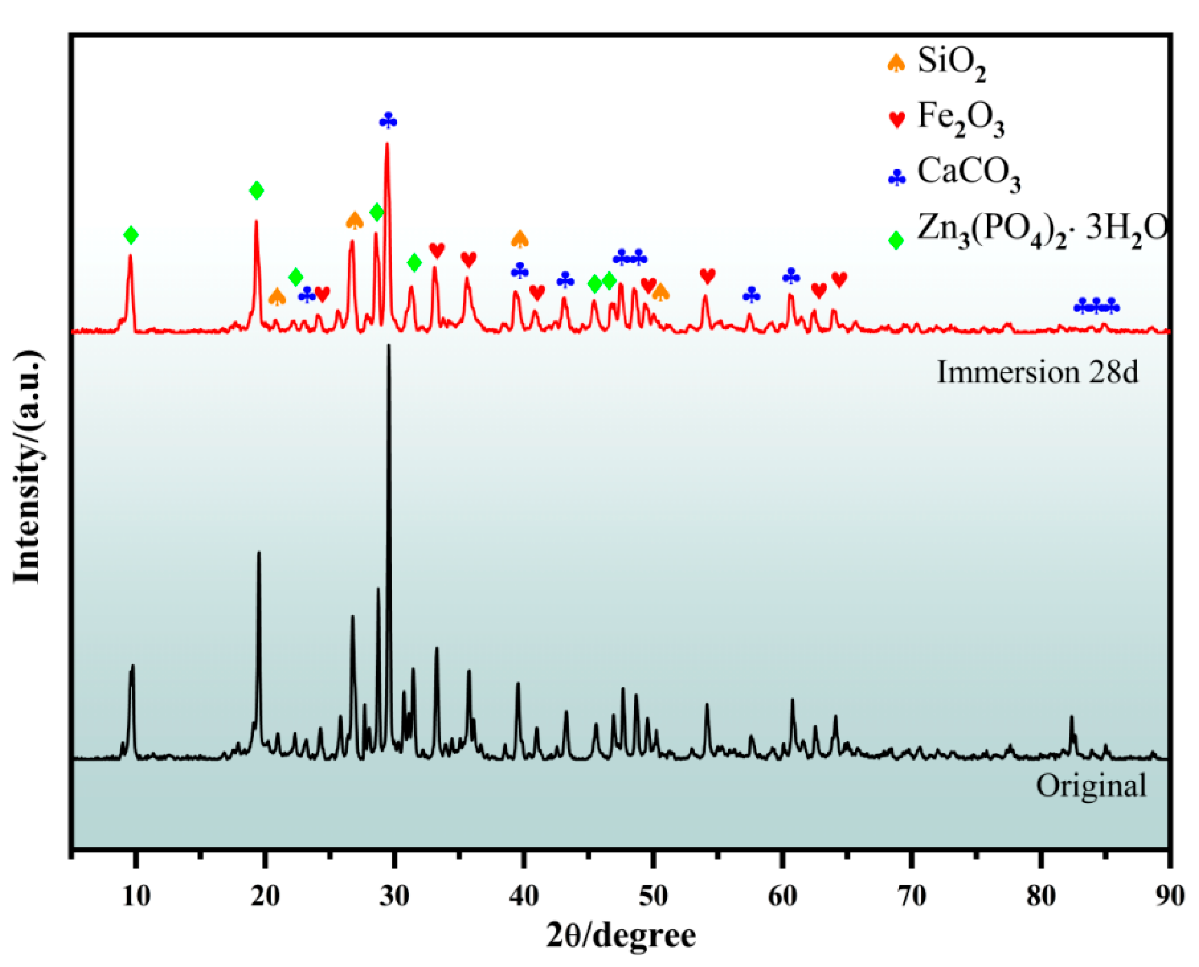
Phase analysis of modified composite coating G10 before and after seawater immersion is shown in Figure 11. It can be seen that the phase composition of the composite coating did not change before and after seawater immersion, indicating that no corrosion products were produced on the surface of the coating. During seawater immersion, the structural stability of the composite coating was good, and no different phases were produced. The stable structure of the coating can reduce the dissolution of the internal GO as much as possible, thus reducing the damage caused by GO to marine life [23]. According to the above electrochemical impedance spectroscopy analysis, it can also be seen that the interface between the composite coating and the substrate has just bubbled or spalled, the corrosion behavior is in the initial stage, and the corrosion products still do not appear on the surface of the coating.

3.5. Failure Mechanism Analysis of Coating

Based on the water absorption, electrochemical impedance spectroscopy, phase analysis and microscopic morphology observation and analysis of the composite coating, the failure mechanism diagram of the coating in simulated seawater, as shown in Figure 12, was obtained. At the initial stage of immersion of the composite coating, the corrosive medium stops on the surface of the coating. At this time, the corrosion resistance of the coating is the maximum, and the double electric layer capacitance of the composite coating is the minimum. As the corrosive medium begins to penetrate the composite coating, it gradually dips into the interior of the coating. In the middle stage of corrosion, the penetration rate of the corrosive medium gradually changes from fast to slow and gradually tends to saturation. Water molecules in the corrosive medium will affect the polymer and cause the coating to swell. At this time, the ion conductivity of the composite coating increases significantly, the resistance of the composite coating decreases sharply, and the double electric layer capacitance of the composite coating increases slowly until 350 h later. The corrosive medium in the composite coating reaches saturation, which belongs to the gestation stage of matrix corrosion. At the end of immersion, local bubbling and spalling occur at the interface between the composite coating and the substrate. The double electric layer capacitance increases sharply with the process at the interface between the composite coating and the substrate, from local spalling to whole spalling, and the coating resistance gradually decreases. From then on, the corrosion of the substrate begins, and the protective effect of the coating begins to fail until it completely fails.

4. Conclusions

With the enhancement of environmental protection awareness, water-based coatings will gradually replace traditional oil-based coatings. This paper focuses on the study of the structure and properties of water-based epoxy-modified silicone coatings, and the research results provide reference values for the exploration of water-based silicone coatings. In this paper, graphene oxide as a nanofiller was introduced into the composite coating for modification, and the performance of the graphene oxide-modified composite coating was systematically studied. The composite coating with the best comprehensive performance was obtained when the amount of graphene oxide was 0.1 wt. %, and the best modified composite coating was immersed in simulated seawater to study its failure behavior. The filler, different contents of GO, in the modified composite coating is uniformly distributed, all states are compatible, and the impedance modulus of the coating |Z| can reach 108 Ω·cm2. The composite coating shows good hydrophobic properties at 0 s water contact, i.e., an angle greater than 90°, which also results in a good dynamic anti-fouling effect. The structure of the composite coating is relatively stable before and after immersion in seawater. The long-term corrosion rule of the composite coating in simulated seawater has been deeply studied. Through the data analysis of the test results, the failure process of the composite coating is rationally explained, and the mechanism diagram of the failure process is drawn.

Author Contributions

Conceptualization, J.X.; Formal analysis, J.L.; Data curation, W.T.; Writing—original draft, Z.C.; Writing—review & editing, Z.Z. All authors have read and agreed to the published version of the manuscript.

Funding

This work was supported by the National Nature Science Foundation of China (No. 51872072), Special funding for the development of science and technology of Shanghai Ocean University (No. A2-0203-00-100231 and A2-2006-00-200371).

Institutional Review Board Statement

Not applicable.

Informed Consent Statement

Not applicable.

Data Availability Statement

Data are contained within the article.

Conflicts of Interest

The authors declare no conflict of interest.

References

  1. Zhang, K.; Cong, W.; Gui, T.; Xing, T.; Wu, L. Effect and Remediation of Biofouling on Marine Aquaculture. Mater. Rep. 2020, 34, 78–81. [Google Scholar]
  2. Sun, B.-K.; Fan, H.-S.; Pan, X.-L.; Lu, A.-D.; Hu, J.-K. Development of Copper-free Self-polishing Anti-fouling Paints by Using Acrylate Resin. Surf. Technol. 2022, 51, 280–286. [Google Scholar]
  3. Xu, F.; Wang, T.; Bohling, J.; Maurice, A.M.; Chen, H.; Wu, L.; Zhou, S. Extended hydrophobicity and self-cleaning performance of waterborne PDMS/TiO2 nanocomposite coatings under accelerated laboratory and outdoor exposure testing. J. Coat. Technol. Res. 2018, 15, 1025–1034. [Google Scholar] [CrossRef]
  4. Khanjani, J.; Pazokifard, S.; Zohuriaan-Mehr, M.J. Improving, dirt pickup resistance in wat erborne coatings using latex blends of acrylic/PDMS polymers. Prog. Org. Coat. 2017, 102, 151–166. [Google Scholar] [CrossRef]
  5. Wang, Q.; Li, C.; Li, G. Study on stability of water-based two-component, i norganic coatings based on silica sols. Electroplat. Finish. 2021, 40, 654–659. [Google Scholar]
  6. Shan, X.; Wang, S.; Zhang, L.; Jiang, L. Preparation of silica sol-based water-based pure in organic coatings. Appl. Chem. Ind. 2018, 47, 1195–1199. [Google Scholar]
  7. Wang, C.; Zhao, L.; Jia, J.; Wang, D.; Peng, Z. Effect of mixed acid functionalized carbon nanotubes doping on the electrical and thermal conductivity of epoxy resin. Trans. China Electrotech. Soc. 2019, 34, 457–464. [Google Scholar]
  8. Tian, Y.; Xie, Y.; Dai, F.; Huang, H.; Zhong, L.; Zhang, X. Ammonium-grafted graphene oxide for enhanced corrosion resistance of waterborne epoxy coatings. Surf. Coat. Technol. 2020, 383, 125227. [Google Scholar] [CrossRef]
  9. Huang, S.; Kong, G.; Yang, B.; Zhang, S.; Che, C. Effects of graphene on the corrosion evolution of zinc particles in waterborne epoxy zinc-containing coatings. Prog. Org. Coat. 2020, 140, 105531. [Google Scholar] [CrossRef]
  10. Li, S.; Zhang, S.; Yang, B.; Guo, H.; Li, Y.; Wen, F. Research progress of graphene anticorrosive coatings. Corros. Sci. Prot. Technol. 2019, 31, 455–461. [Google Scholar]
  11. Chen, S.; Brown, L.; Levendorf, M.; Cai, W.; Ju, S.Y.; Edgeworth, J.; Li, X.; Magnuson, C.W.; Velamakanni, A.; Piner, R.D.; et al. Oxidation resistance of graphene-coated Cu and Cu/Ni alloy. ACS Nano 2011, 5, 1321–1327. [Google Scholar] [CrossRef]
  12. Chen, C.; He, Y.; Xiao, G.; Zhong, F.; Xia, Y.; Wu, Y. Graphic C3N4-assisted dispersion of graphene to improve the corrosion resistance of waterborne epoxy coating. Prog. Org. Coat. 2020, 139, 105448. [Google Scholar] [CrossRef]
  13. Jiang, Y.; Jiang, H.Y.; Xiong, S.P. Effect of Reduced Graphene Oxide on Corrosion Resistance of Waterborne Inorganic Zinc-rich Coatings. Paint. Coat. Ind. 2023, 53, 68–72. [Google Scholar]
  14. Xiao, P.; Wang, D.-H.; Lang, J.-W. Comparison in Factors Affecting Electrochemical Properties of Thermal-Reduced Graphene Oxide for Supercapacitors. J. Electrochem. 2014, 20, 553–562. [Google Scholar]
  15. Darowicki, K. The application of impedance measurements for the determination of the probability of the course of corrosion processes. Corros. Sci. 1997, 39, 1087–1092. [Google Scholar] [CrossRef]
  16. Wang, W.J.; Guan, Z.C.; Han, J.C.; Xu, H.; Jin, X.; Di, Z.G. Application of Electrochemical Impedance Spectroscopy in the Evaluation of Protective Performance of Organic Coating. Paint. Coat. Ind. 2023, 53, 58–64. [Google Scholar]
  17. Gao, L.X.; Zhang, D.Q.; Zhou, G.D.; Li, H.G. Study on water absorption and corrosion protection properties of modified epoxy coatings. Chin. J. Corros. Prot. 2002, 22, 41–43. [Google Scholar]
  18. Van Westing, E.P.M.; Ferrari, G.M.; De Wit, J.H.W. The determination of coating performance with impedance measurements—II. Water uptake of coatings. Corros. Sci. 1994, 36, 957–977. [Google Scholar] [CrossRef]
  19. Cai, G.; Zhang, D.; Zhao, W.; Dong, Z. Research progress on protection performance and failure evaluation of organic coatings. Corros. Prot. 2017, 38, 657–664. [Google Scholar]
  20. Yuan, S.J.; Chong AM, F.; Pehkonen, S.O. The influence of the marine aerobic Pseudomonas strain on the corrosion of 70/30 Cu-Ni alloy. Corros. Sci. 2007, 49, 4352–4358. [Google Scholar] [CrossRef]
  21. Yang, L.H.; Liu, F.C.; Zhang, Z.Q.; He, P.; Han, E.H.; Qi, L. Research on the Anti-Diffusion Behavior of ZnO/Polyurethane Coatings. J. Peking Univ. Nat. Sci. 2006, 91–96. [Google Scholar]
  22. Wu, C.; Lin, Z.; Li, X.; Ma, B.; Xu, L. Electrochemical Corrosion Behavior of Zinc Powder Sherardized Carbon Steel. Corros. Sci. Prot. Technol. 2014, 26, 441–445. [Google Scholar]
  23. de Medeiros, A.M.; Khan, L.U.; da Silva, G.H.; Ospina, C.A.; Alves, O.L.; de Castro, V.L.; Martinez, D.S. Graphene oxide-silver nanoparticle hybrid material: An integrated nanosafety study in zebrafish embryos. Ecotoxicol. Environ. Saf. 2021, 209, 111776. [Google Scholar] [CrossRef] [PubMed]
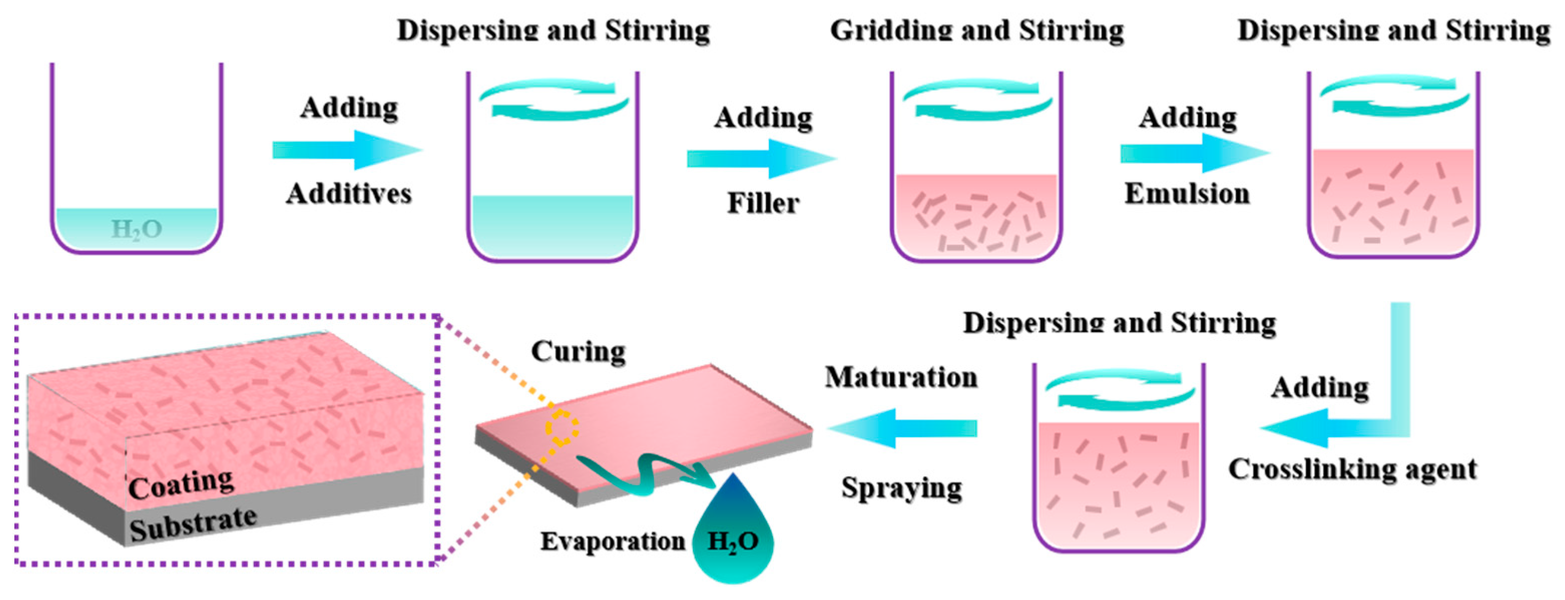
Figure 1. Schematic diagram of composite coating preparation process.
Coatings 14 00586 g001
Figure 2. Optical and electron microscope images of cross sections of GO composite coatings with different contents: (a,f) G0, (b,g) G1, (c,h) G5, (d,i) G10, (e,j) G15.
Coatings 14 00586 g002
Figure 3. Changes in dynamic water contact Angle of composite coatings with different GO contents.
Coatings 14 00586 g003
Figure 4. Impedance spectra of modified composite coatings with different GO contents: (a) Nyquist diagram; (b) Nyquist local magnification diagram; (c) impedance modulus |Z| diagram; (d) phase angle diagram.
Coatings 14 00586 g004
Figure 5. Analog equivalent circuit diagram of modified composite coating with different GO contents.
Coatings 14 00586 g005
Figure 6. GO equivalent circuit diagram with different content parameter variation diagram: (a) coating resistance and solution resistance variation diagram, (b) diagram of coating capacitance variation.
Coatings 14 00586 g006
Figure 7. Water absorption of G10 coating—time variation diagram.
Coatings 14 00586 g007
Figure 8. Variation in the impedance spectrum of the composite coating with seawater immersion time: (a) Nyquist plot, (b) Nyquist local enlarged image, (c) Bode modulus |Z| diagram, (d) Bode phase angle diagram.
Coatings 14 00586 g008
Figure 9. Variation trend of (a) parameters CPEdl, (b) Rs and Rct in equivalent circuit diagram.
Coatings 14 00586 g009
Figure 10. Comparison of the micromorphology of composite coating G10 after 28 days of immersion in simulated seawater: (a) The original morphology of the coating, the morphology of the coating after 28 days of immersion in simulated seawater figure (b), and the local enlarged figure (c).
Coatings 14 00586 g010
Figure 11. Phase analysis of composite coating G10 before and after 28 d seawater immersion.
Coatings 14 00586 g011
Figure 12. Failure mechanism of composite coating G10 coating in simulated seawater. (a) At the initial stage of immersion; (b) at the middle stage of immersion; (c) at the beginning stage of late immersion.
Coatings 14 00586 g012
Table 1. Equivalent circuit fitting parameters of different contents of graphene oxide-modified composite coatings.
Content (wt. %)Rs (Ω·cm−2)Error (%)CPEdl (F)Error (%)Rct (Ω·cm−2)Error (%)Goodness of Fit
00.001262.06 × 1071.416 × 10−111.40475,9100.54750.00133
0.01846.657.381.474 × 10−111.6471.024 × 1061.160.00547
0.0516,86023.761.546 × 10−111.371.351 × 1070.90590.00404
0.111,14051.881.761 × 10−111.8231.673 × 1081.9870.011
0.1517,08027.352 × 10−111.8633.064 × 1071.6210.00909
Table 2. The fitting parameters of the equivalent circuit diagram of electrochemical impedance spectra corresponding to different soaking periods.
Time (Day)Rs (Ω·cm−2)Error (%)CPEdl (F)Error (%)Rct (Ω·cm−2)Error (%)Goodness of Fit
0556325.624.104 × 10−111.0289.353 × 1071.1643.62 × 10−3
1458719.994.426 × 10−111.0541.266 × 1060.62271.72 × 10−3
4515717.164.566 × 10−111.926142,0000.75061.34 × 10−3
7407010.424.686 × 10−111.56163,9600.65462.196 × 10−4
14281012.094.823 × 10−111.28362,4200.53771.562 × 10−4
21210912.945.298 × 10−112.39823,6701.1334.756 × 10−5
28331320.036.327 × 10−117.79517,5703.722.71 × 10−4
Disclaimer/Publisher’s Note: The statements, opinions and data contained in all publications are solely those of the individual author(s) and contributor(s) and not of MDPI and/or the editor(s). MDPI and/or the editor(s) disclaim responsibility for any injury to people or property resulting from any ideas, methods, instructions or products referred to in the content.