Abstract
In this study, a HfO2 coating was developed on an Ir matrix using a customized open-tube airflow, cold-wall chemical vapor deposition instrument. The preparation process and structure of the as-prepared coating were investigated to gain insights into its characteristics. The HfO2 coating effectively prevents direct contact between Ir and O, leading to a reduction in the oxidation rate of Ir. Furthermore, defects such as micropores and cracks generated during sealed oxidation erosion contribute to Ir’s decelerated oxidation failure. The as-prepared HfO2 coating exhibits low thermal conductivity and a high heat radiation rate, reducing the coating’s surface temperature. These characteristics significantly enhance adversity tolerance and increase the working temperature of the coating. Moreover, the as-prepared HfO2 coating can serve as a diffusion barrier, blocking both the direct contact of O with the Ir coating and the diffusion of other elements to the Ir coating. As a result, the rates of diffusion of other elements to the Ir coating are reduced.
1. Introduction
Thermal barrier coatings (TBCs) are used to mitigate material degradation caused by high heat flux [1]. The application of a TBC maintains the thermal gradient between the coating surface and the substrate surface, thereby improving operating temperature range and efficiency. TBCs are widely used in the energy, automotive, aerospace, electronics and power industries [2].
The working temperature of the combustion chamber nozzle predominantly determines the performance of aerospace engines. Currently, Re/Ir composite nozzles can operate at temperatures of up to 2200 °C [3,4,5]. However, at high temperatures, Re is susceptible to oxidation and volatilization [6]. In contrast, Ir exhibits excellent thermal and chemical stability, allowing it to operate under weakly oxidizing atmospheres and high-temperature airflows below 2200 °C for prolonged periods [7]. Consequently, Re/Ir nozzles have garnered significant research interest for high-performance engine applications.
Although Re/Ir nozzles are suitable for the commonly used nitrogen tetroxide/monomethylhydrazine (NTO/MMH) propellant [8,9,10], this propellant poses substantial environmental risks due to its high toxicity, flammability, explosiveness, and potential to pollute the Earth’s atmosphere and space. To address these concerns, countries and regions engaged in space exploration, including China, have been actively developing safer green propellants, such as O2/H2 [11,12,13], as alternatives to NTO/MMH. Green propellants and their combustion products are substantially more oxidizing than NTO/MMH and their combustion products. Unfortunately, an Ir coating alone does not protect against oxidation in this operating environment. Consequently, Re/Ir composite nozzles cannot sustain prolonged operation when subjected to green propellants with a working temperature of 2200 °C.
Aerospace engines operate in continuous ignition mode, with extremely short ignition times. To enhance the high-temperature oxidation resistance of a Re/Ir nozzle, a metallic oxide coating with a high melting point can be applied to the inner surface of the nozzle. This metallic oxide coating effectively lowers the working temperature of Ir, thereby reducing the oxidation rate of the Ir coating without compromising the overall working temperature of the engine. Additionally, the metallic oxide coating prevents direct contact between Ir and the combustion products of the propellant, significantly reducing the oxidation rate and erosion of the surface of the Ir layer by high-temperature airflow. As a result, the service life of the Ir layer is prolonged, effectively extending the overall lifespan of the engine. The metallic oxide coating serves the dual function of acting as a thermal and diffusion barrier [14].
When selecting metallic oxides with high melting points, factors such as the melting point of the metal oxide and its vapor pressure, thermal conductivity, and compatibility with Ir’s coefficient of thermal expansion are considered. The current domestic research on high-temperature oxidation-resistant coatings mainly focuses on ZrO2 and Al2O3 coatings [15,16,17,18], as they have high melting points, low coefficients of thermal expansion, and good thermal compatibility with the matrix, which are essential characteristics for high-temperature oxidation-resistant coatings. However, a substantial difference exists in the thermal expansion coefficients between ZrO2, Al2O3, and Ir, resulting in poor thermal compatibility between them [19,20]. Furthermore, ZrO2 will transition from a tetragonal phase t to a monoclinic phase m at high temperatures. Volume change is the main reason for the cracking of the coating [21]. On the other hand, Al2O3 has relatively high thermal conductivity, limiting its ability to provide adequate thermal barrier performance for the Ir layer. Considering these factors, the oxide HfO2, incorporating the element Hf, which is in the same group as Zr, emerges as an ideal alternative. HfO2 has a high melting point, a coefficient of thermal expansion close to that of Ir (with only a 0.4 × 10⁻⁶/K difference), low thermal conductivity, and a low evaporation rate [22,23]. These properties demonstrate excellent thermal compatibility, performance, and diffusion barrier capabilities [24,25], making HfO2 one of the most suitable materials for high-temperature oxidation-resistant aerospace engine nozzles.
The preparation methods for HfO2 coatings are various, but there are still many bottlenecks in the preparation process. It is necessary to select the appropriate preparation methods and process conditions according to the performance requirements, production scale, the application environment, and other factors. At present, the common preparation methods for HfO2 coatings are chemical vapor deposition (CVD) [26], physical vapor deposition (PVD) [27], the sol–gel method [28], atomic layer deposition (ALD) [29], sintering [30], etc. The preparation cycles of the sol–gel, ALD, and PVD methods are longer than the others. The controllability of sintering preparation is insufficient. Chemical vapor deposition is a good choice for preparing HfO2 coatings when seeking to ensure uniformity, controllability, and preparation efficiency at the same time.
This paper addresses the challenges related to superhigh-temperature noble metal/outer composite coatings. The main focus of this study is the investigation of the preparation, structure, defects, and oxidation resistance of an Ir/HfO2 composite coating. This research aims to establish a solid foundation for meeting the demands of the new generation of aerospace engines, particularly in regard to selecting appropriate superhigh-temperature coating materials able to withstand extreme conditions such as higher working temperatures and more robust oxidation environments.
2. Materials and Methods
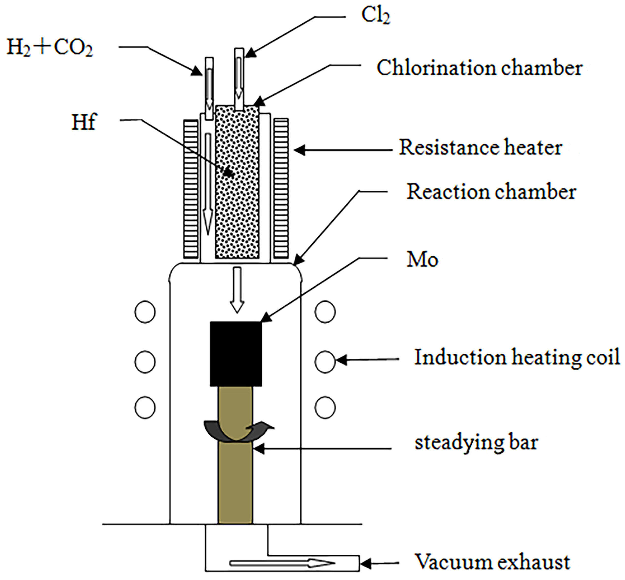
The HfO2 coating was prepared using the open-tube airflow, low-pressure cold-wall chemical vapor deposition technique. The deposition process was divided into two stages: the chlorination of Hf in a chlorination chamber and the redox of HfCl4 in a reaction chamber. During the Hf chlorination stage, electric furnace heating was employed to heat the Hf. Conversely, in the HfCl4 redox stage, the matrix was heated using the medium-frequency induction method. The equations describing the reaction are shown in Equations (1) and (2).
Hf (s) + 2Cl2 (g) → HfCl4 (g)
HfCl4 (g) + 2CO2 (g) + 2H2 (g) → HfO2 (s) + 2CO (g) + 4HCl (g)
The experimental chemical vapor deposition apparatus was self-designed and -assembled, and a schematic diagram of it is illustrated in Figure 1.
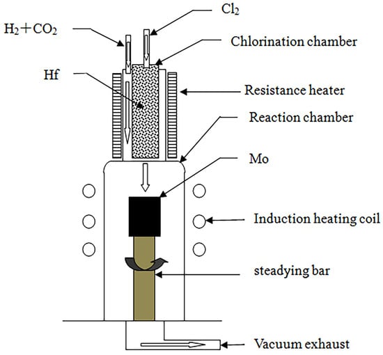
Figure 1.
Schematic of the CVD process for the preparation of HfO2 coatings.
The experimental setup included the following components:
- (1)
- Chlorination chamber: A 65 mm diameter quartz tube was selected as the chlorination chamber, wherein Hf was heated using a self-assembled resistance furnace, and its temperature was measured with a platinum–rhodium alloy thermocouple. A CY digital display temperature controller was employed to control the temperature in the furnace.
- (2)
- Deposition chamber: A quartz tube with a diameter of 86 mm was selected as the deposition chamber, and the matrix was heated using the medium-frequency induction method. The tube’s surface temperature was measured using an infrared thermometer (WGG2-201N) (the measurement error was maintained at ±5 °C), and a self-assembled electric control cabinet was used to control the temperature.
- (3)
- Gas supply system: After drying was allowed, the reaction gas flow rate was controlled using a glass-rotor gas flow meter, which was introduced into the chlorination chamber and deposition chamber through a rubber tube.
- (4)
- Exhaust treatment system: A 2X-4 vacuum pump was used to extract the reaction residue. To prevent blockage of the pumping pipeline, a glass-filled filtration device was installed between the vacuum pump and the deposition chamber to prevent powder byproducts from being generated during the deposition process. The filtered exhaust gas was fed into a dilute NaOH solution for treatment.
The Ir/HfO2 composite coating was prepared using a Mo core in a powder metallurgical processing state as the base. The HfO2 coating was first deposited on the Mo matrix, and the Ir coating was then prepared, via chemical vapor deposition, on the HfO2 coating. Additionally, the vacuum degree in heat treatment was not less than 10−2 Pa, and the heat treatment temperature was not less than 1400 °C.
A scanning electron microscope (SEM) was employed to scan the specimen using a focused high-energy electron beam, enabling the observation of the surface morphology of the specimen by accepting and amplifying various types of information excited by the high-energy electron beam. The SEM used allowed adjustable magnification within a wide range, boasting high resolution and a large depth of field, making it suitable for analyzing the surface microstructures of diverse samples. In this experiment, the surface morphology of the HfO2 coating was observed using the SPM-S3400N scanning electron microscope produced by Hitachi.
The wavelength dispersive spectrometry (WDS) module of the Electron Probe X-ray Micro-Analyzer (EPMA) was used to analyze the composition of the coating surface. The accelerating voltage used was 15 kv. The scanning speed was 45 ms/point.
For X-ray diffraction analysis of the HfO2 coating prepared via CVD, a RIGAKU D/max-2200 X-ray diffractometer from Tokyo, Japan was employed. In this test, we employed a Cu target, with a light tube voltage of 40 kV and a current of 100 mA. Furthermore, the step width was set to 0.02°, and the rate of movement was 5°/min. DS/SS was set to 1°, and RS was set to 0.3 mm. The diffraction angle (2θ) ranged from 10 to 90°. The measured diffraction peaks were calibrated using a standard PDF card to determine the phase structure of the coating.
3. Results and Discussion
3.1. Microstructure and Composition of Ir/HfO2 Composite Coating
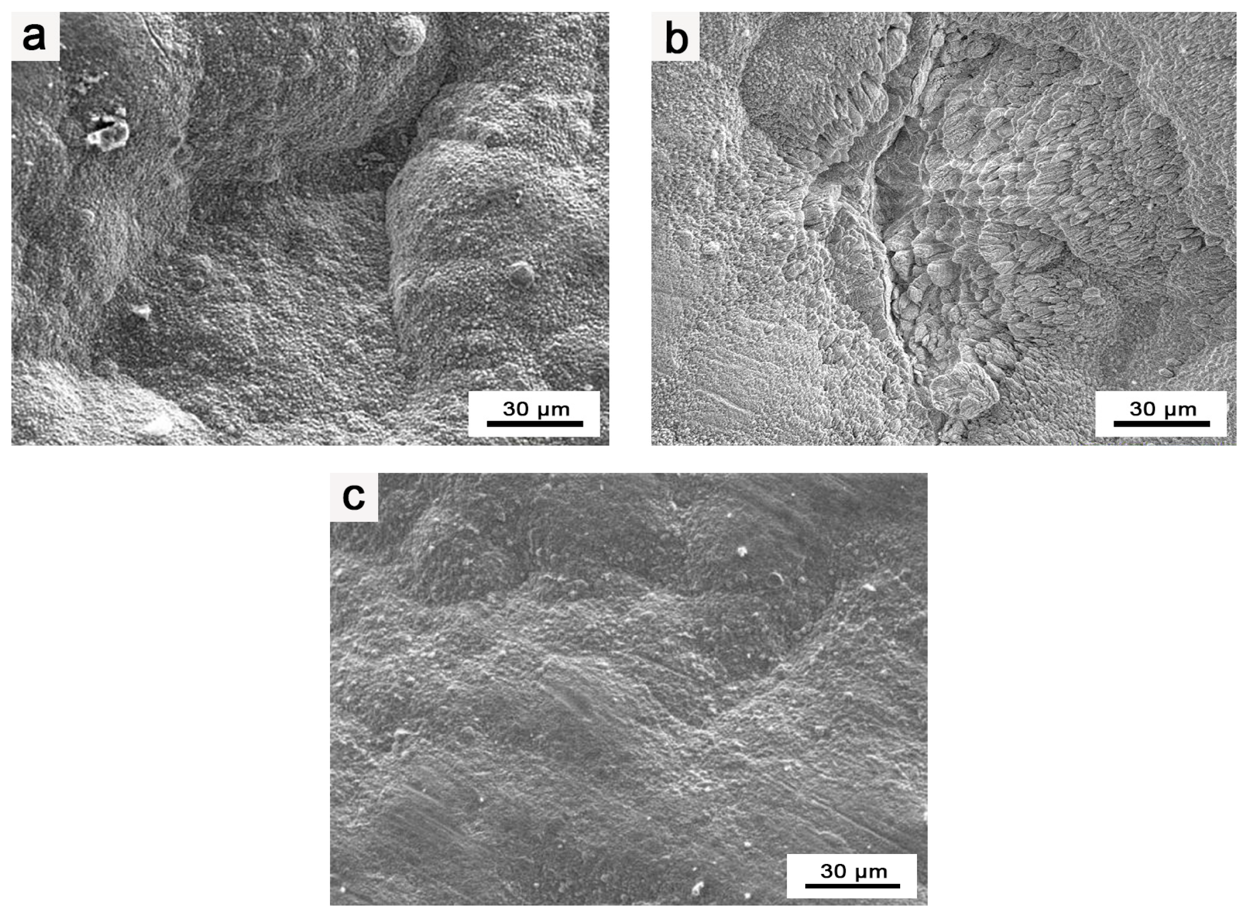
During the heat treatment and preparation of the Ir layer in the composite coating, surface blistering and cracking were observed on the Ir coating. Notably, the blistering and cracking phenomena became more pronounced during heat treatment, as presented in Figure 2a,b.
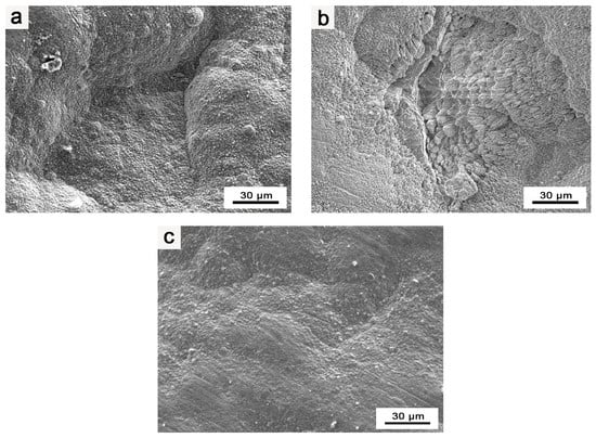
Figure 2.
EPMA images of Ir coating: (a) surface morphology of blisters in composite coatings; (b) surface morphology of cracks in composite coatings; (c) surface morphology of flat and intact composite coating.
Through an analysis of the experimental process, a possible explanation is proposed. The surface blistering and cracking of the Ir coating primarily result from gas adsorption by the as-prepared HfO2 coating during the process of increasing the temperature in the heat treatment and Ir layer preparation stages of the composite coating. This gas release weakens the bonding between Ir and HfO2. Subsequently, during the heat treatment of the composite coating, the released gas expands substantially under high temperatures, leading to the cracking and peeling of the coating. As a result, after the preparation of the coating, the pores in the coating adsorb some gas. On the other hand, in the preparation of the Ir coating, the lower reaction temperature and positive pressure of the preparation process result in less evident blistering and cracking on the surface of the Ir coating. However, during the heat treatment of the composite coating, conducted at higher temperatures (≥1400 °C), the blistering and cracking on the surface of the composite coating become more severe, and instances of the coating peeling are observed.
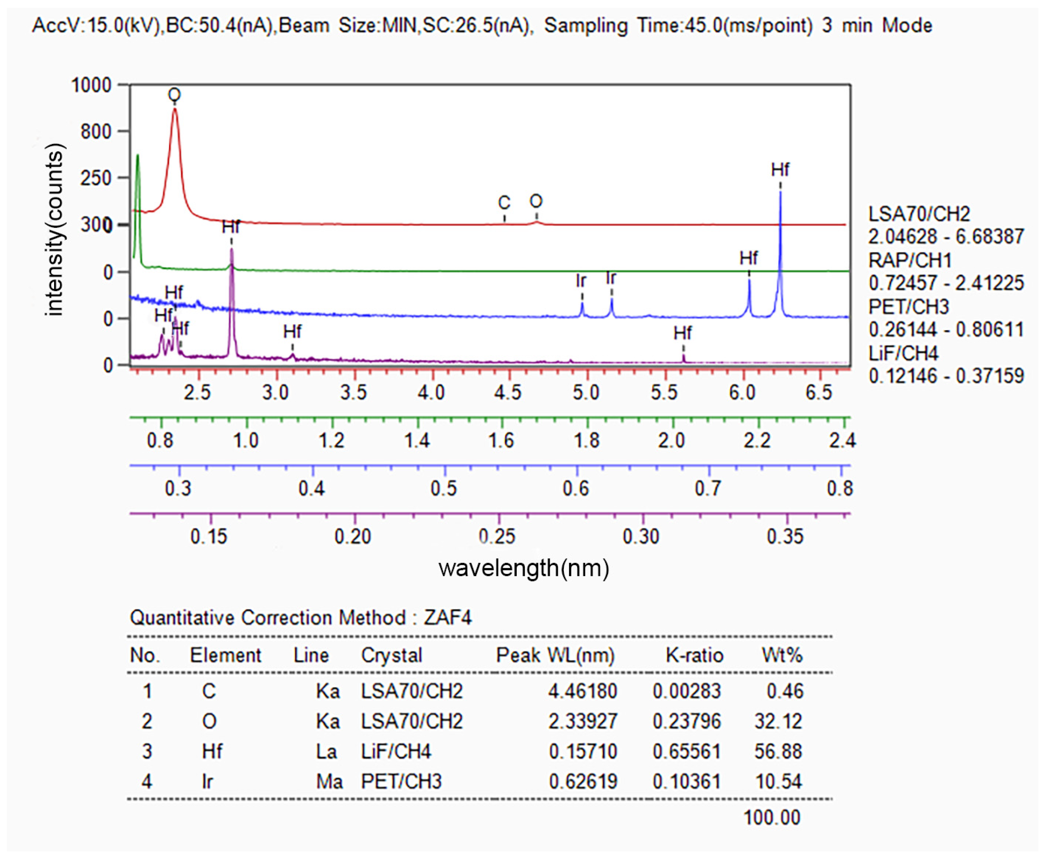
The composition of the area wherein the blistering and cracking of the Ir coating occurred was analyzed using EPMA, and the results are presented in Figure 3. It can be observed that this area exhibits a high content of hafnium and oxygen, along with a certain amount of carbon.
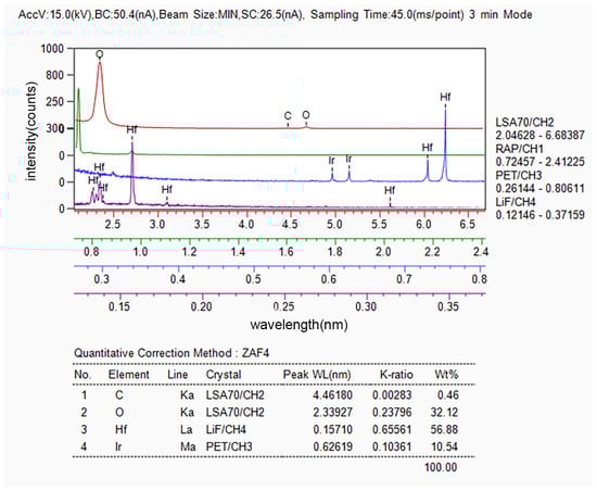
Figure 3.
Composition of blisters and cracks in the composite coatings determined via WDS.
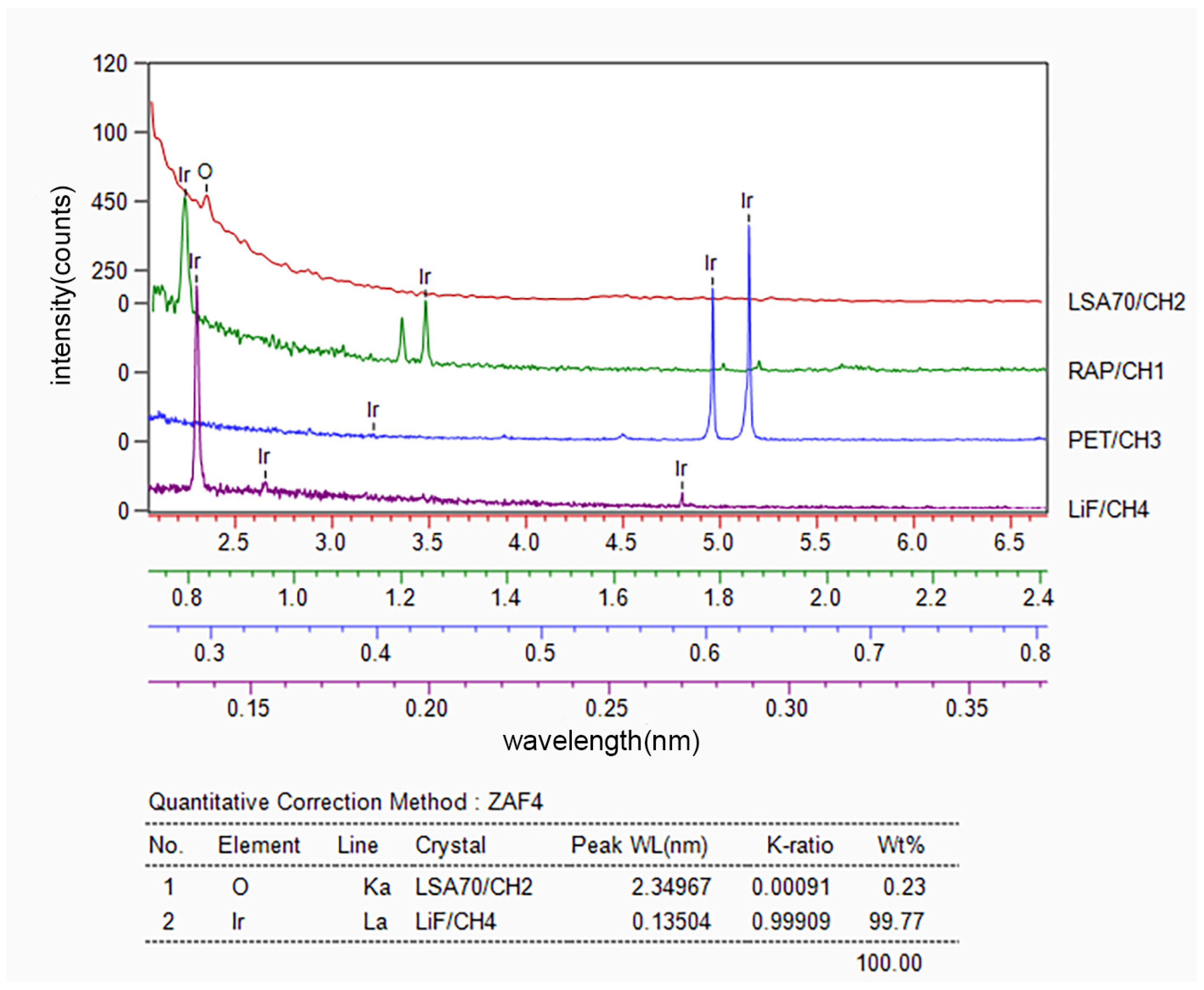
After implementing various improvements, a slow-warming vacuum degassing process was applied before the secondary preparation of HfO2 in the subsequent experiments. Additionally, in preparing the Ir coating, a slow-warming high-vacuum degassing process was also applied before the deposition, aimed at minimizing the adsorbed gas in the pores of HfO2. This approach proved to be considerably effective in addressing the issue in question. The slow-heating method was adopted to prevent the rapid escape of gas, which could otherwise damage the coating during rapid heating. As a result of applying this improved process, the surface of the Ir/HfO2 composite coating appeared relatively flat and smooth, devoid of evident bubbling and cracking, as illustrated in Figure 2c. Figure 4 displays the composition of the Ir/HfO2 composite coating prepared using the improved process.
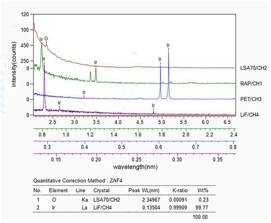
Figure 4.
Composition of the flat and intact composite coating determined via WDS.
3.2. Oxidation Resistance and Structure of Ir and Ir/HfO2
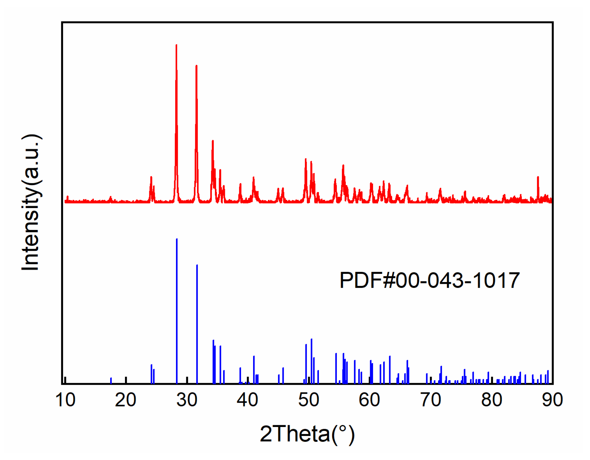
In Figure 5, it can be seen that the diffraction peak position of the HfO2 coating prepared using the CVD method is consistent with the standard spectrum. There are no obvious shifts or broadening phenomena, indicating that the obtained coating is a pure HfO2 coating with a monoclinic crystal structure at room temperature.
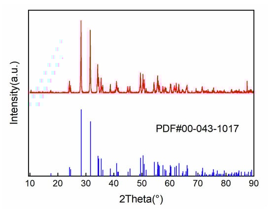
Figure 5.
XRD results of HfO2 coating.
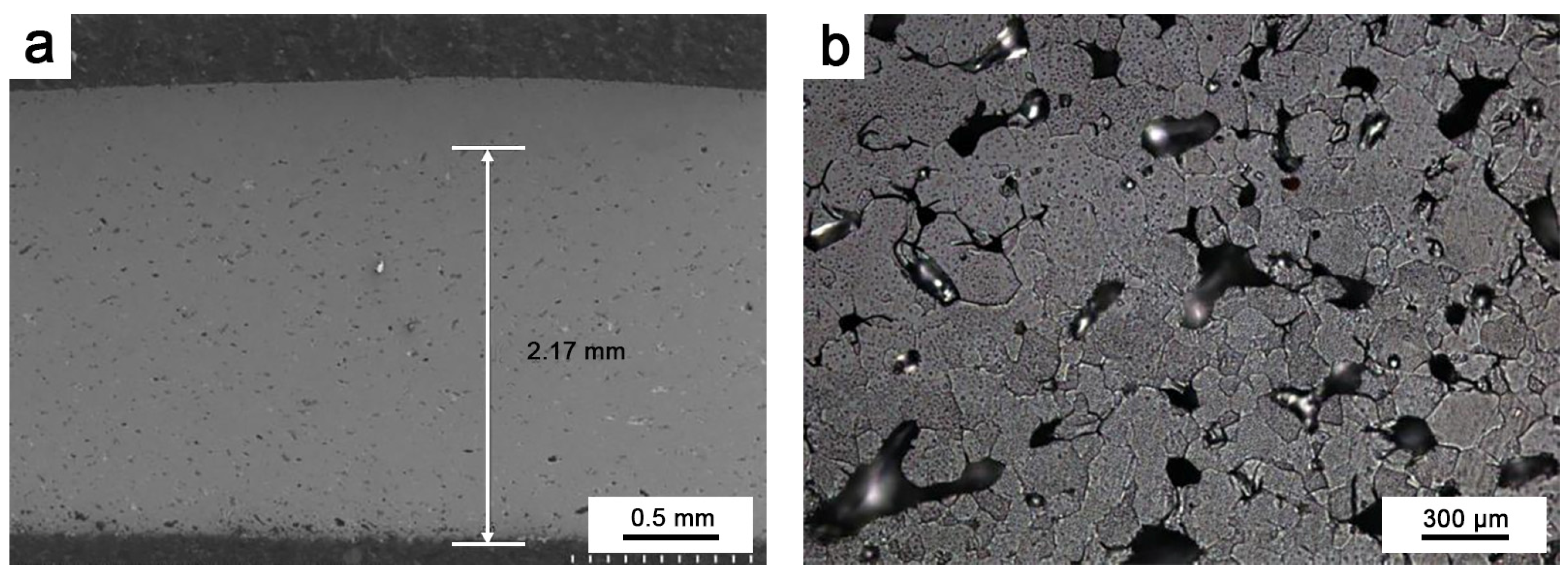
To investigate the protective effect of oxidation on Ir, oxidation tests were performed at 1980 °C for 10 h on round Ir rods treated with hot isostatic pressing and round Ir rods with an HfO2 coating. The oxidation of pure Ir proceeded as follows: After the oxidation test, a sample that was approximately 2–3 mm thick was cut from the end face. It was inlaid so that it could be polished, and the longitudinal section was observed, as shown in Figure 6a. Figure 6b depicts the outermost layer of pure Ir oxidation observed via a metallographic microscope. Figure 7 illustrates the fault morphology of Ir/HfO2 before and after oxidation, respectively.
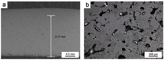
Figure 6.
(a) Oxidation depth of pure Ir; (b) oxidized metallographic phase of pure Ir.
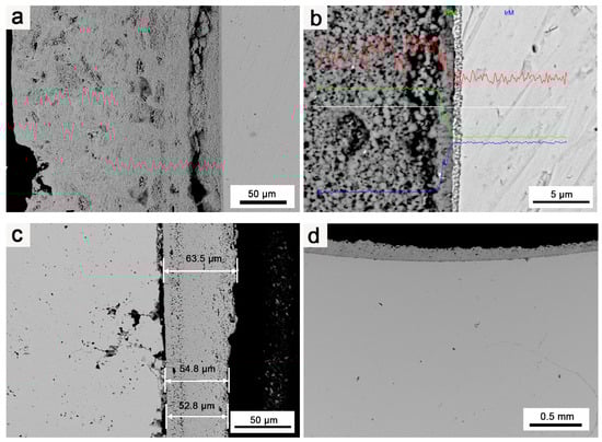
Figure 7.
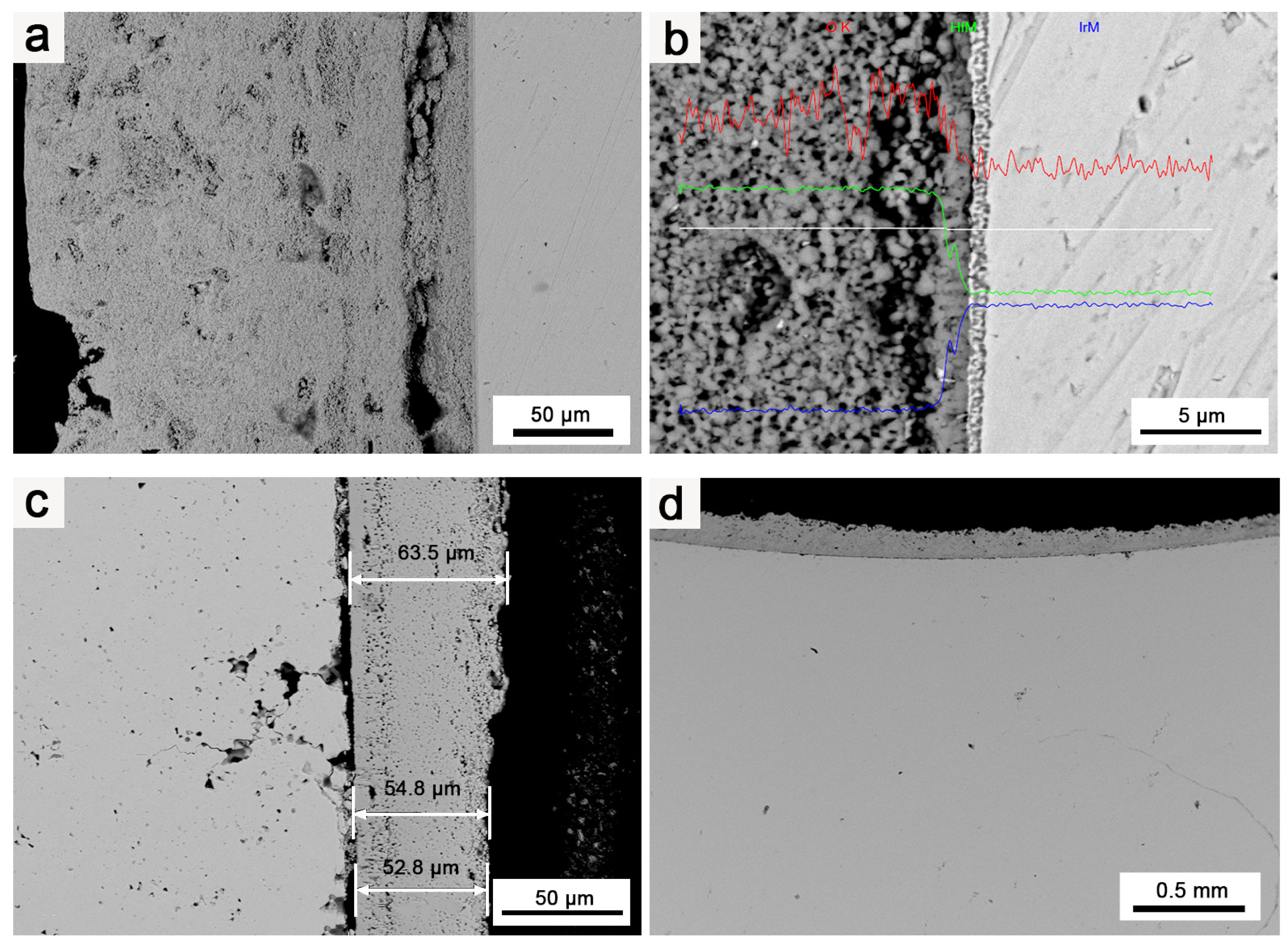
SEM images of Ir/HfO2 coating: (a) Ir/HfO2 before oxidation; (b) EDS of Ir/HfO2 before oxidation; (c,d) Ir/HfO2 after oxidation.
As depicted in Figure 6, prolonged high-temperature oxidation resulted in considerable oxidation volatilization of Ir, with oxidized holes being observable throughout the depth of the sample till reaching the millimeter level. Some parts even formed penetration holes. At temperatures exceeding 1100 °C, pure Ir cannot form a stable, protective oxide film and directly oxidizes into gaseous iridium dioxide and iridium trioxide [31,32], resulting in the continuous volatilization of Ir at a rate of approximately 35 μm/h in the air at 1965 °C [33]. Ir is oxidized to IrO2 at 650 °C in air. At 1100 °C, IrO2 undergoes thermal decomposition, forming the gaseous oxide IrO3. The equations describing the reaction are shown in Equations (3) and (4) [31,34].
Ir (s) + O2 (g) → IrO2 (s)
2IrO2 (s) + O2 (g) → 2IrO3 (g)
This substantially impacts the service life of a material when used in high-temperature oxidizing environments. Additionally, under high-temperature oxidizing environment conditions, Ir is susceptible to micropore diffusion and agglomeration along grain boundaries, forming rapid diffusion channels along these grain boundaries [35,36,37]. As oxidation proceeds, the density of the micropores in Ir increases, and they agglomerate along the grain boundaries, facilitating outward movement. These grain boundaries, with numerous micropores, provide the shortest diffusion channel for O diffusion, allowing oxygen and matrix elements to diffuse rapidly through the grain boundaries, ultimately leading to the rapid failure of Ir.
Figure 7a,b illustrates the pristine Ir matrix before oxidation, showing no defects or oxidation holes. Figure 7c,d highlight the pronounced protective effect of the HfO2 coating on Ir. Notably, the thickness of the coating considerably influenced the protective effect on Ir. In the thinnest part of the HfO2 coating (50–60 μm across the entire sample), Ir’s oxidation was more noticeable than that in other regions, and an increased number of oxidation holes appeared. Although oxidation and oxidized pores were present in Ir under the protection of the HfO2 coating, there were considerably fewer oxidation holes of Ir in the case of the Ir/HfO2 coating compared to the number for pure Ir. The oxidation depth was only tens of microns, and the oxidized pores were much smaller, with no evidence of micropore diffusion and clustering along the grain boundaries. This observation indicates that the HfO2 coating has a substantial protective effect on Ir.
The deposition of the HfO2 coating on the surface of Ir serves two purposes: Firstly, it blocks direct contact between Ir with O, reducing the oxidation rate of Ir. Secondly, the HfO2 coating acts as a sealant, filling micropores, cracks, and other defects that may occur during the oxidation erosion process, significantly reducing the scope of the oxidation failure of Ir. Additionally, the HfO2 coating exhibits low thermal conductivity and high thermal emissivity (1.5 W/(m·K) [22], 0.38–0.58) compared to Ir (147 W/(m·K), 0.25~0.3), effectively lowering the temperature of the coating surface and significantly increasing the coating’s tolerance of the environment and the overall working temperature.
3.3. Effects of Heat Treatment Temperature on the Microstructure of the Composite Coating
Figure 8 illustrates the microstructures of the Mo/HfO2/Ir/Re composite in the as-deposited state and after 2 h of heat treatment at different temperatures. In the as-deposited state, the bonding between the HfO2 layer and the Ir layer, as well as the Ir layer and the Re layer, was not particularly tight, leaving a certain gap between the components. Combined with the element diffusion shown in Figure 9, only a thin diffusion layer was present in the region of mutual bonding, and the diffusion layer between HfO2 and the matrix was not considerably pronounced. Following heat treatment, interdiffusions were observed between HfO2/Ir and Ir/Re, leading to improved bonding between the different coatings compared to that in their deposited state. The bonding between the coatings further improved upon increasing the heat treatment temperature. Consequently, heat treatment effectively enhanced the bonding between the coatings, reducing the likelihood of detachment from the matrix.
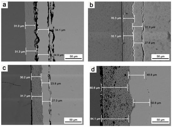
Figure 8.
SEM images of coating’s cross-sections: (a) Structure of composite in the deposition state; (b) structure of composite after it was subjected to 1400 °C for 2 h; (c) structure of composite after it was subjected to 1600 °C for 2 h; (d) structure of composite after it was subjected to 1800 °C for 2 h.
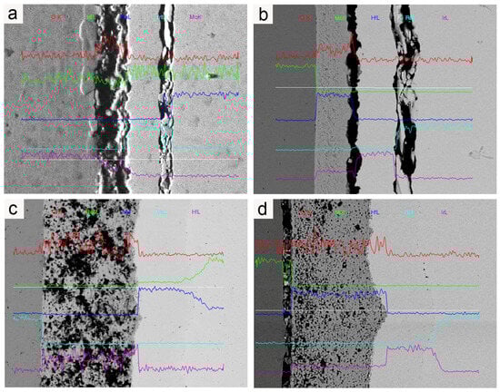
Figure 9.
EDS of coating cross-section: (a) element diffusion in the as-deposited composite; (b) element diffusion in the composite after it was subjected to 1400 °C for 2 h; (c) element diffusion in the composite after it was subjected to 1600 °C for 2 h; (d) element diffusion in the composite after it was subjected to 1800 °C for 2 h.
Nevertheless, a negative consequence was an increase in heat treatment temperature, namely, an increase in Ir/Re interdiffusion. After the composite was heat-treated at 1600 °C for 2 h, Kirkendall voids appeared between the Ir and Re layers. These Kirkendall voids became more pronounced after heat treatment at 1800 °C for 2 h. Ir/Re interdiffusion substantially influenced the service life of the composite coating.
In the initial state, the binding strength between the Ir and HfO2 layers is relatively weak, and the degree of Ir/Re interdiffusion is insignificant. However, following heat treatment, the binding strength between the Ir layer and HfO2 layer improves upon increasing the heat treatment temperature. Simultaneously, Ir/Re interdiffusion increases, leading to a thicker diffusion layer between the Ir and Re layers, along with the appearance of Kirkendall voids between the Ir and Re layers. Furthermore, the element diffusion analysis reveals that the HfO2 layer has a substantial barrier effect on element diffusion both in the as-deposited state and after heat treatment. As a result, the entire composite coating has a very low Mo content.
Apart from oxidative ablation and volatilization, another failure mechanism of the Ir coating involves the diffusion of other elements into the coating, forming a diffusion layer. The Ir coating loses its antioxidant protection once the diffusion layer reaches a certain thickness. Fortunately, the presence of the HfO2 coating acts as a diffusion barrier, serving multiple purposes. Firstly, it blocks direct contact between O and the Ir coating, thereby slowing down the Ir layer’s oxidation and ablation volatilization rates. Second, it effectively hinders the diffusion rate of other elements to the Ir coating, reducing the growth rate of the interdiffusion layer. As a result, the HfO2 coating significantly prolongs the service life of the Ir coating.
3.4. Effects of Heat Treatment Duration on the Composite Coating’s Microstructure
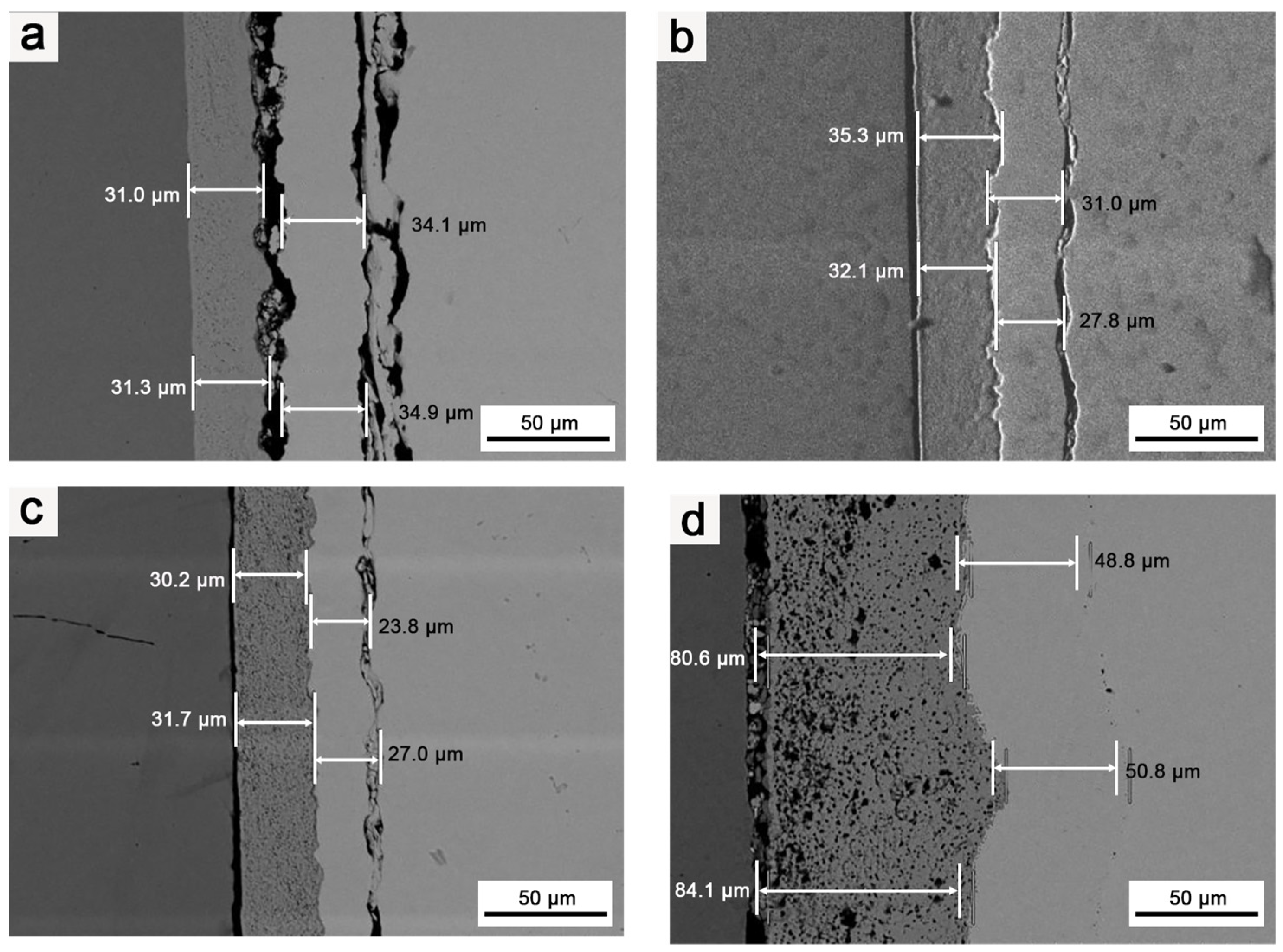
Figure 10 illustrates the effects of various heat treatment of different durations on the microstructures of the composites at 1800 °C.
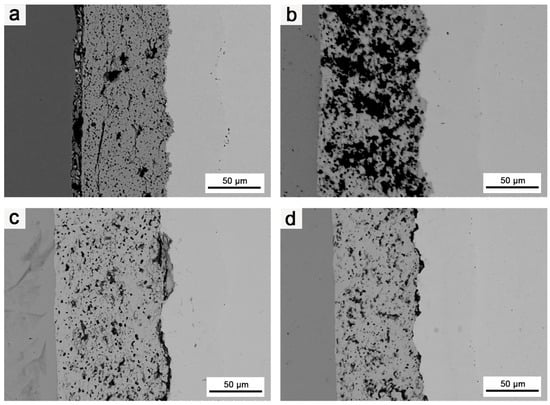
Figure 10.
SEM images of coating cross-section: (a) structure of the composite after it was subjected to 1800 °C for 2 h; (b) structure of the composite after it was subjected to 1800 °C for 3 h; (c) structure of the composite after it was subjected to 1800 °C for 4 h; (d) structure of the composite after it was subjected to 1800 °C for 5 h.
As the heat treatment duration increased, the bonding between the HfO2 layer and Mo matrix, as well as between the different coatings, gradually improved. Therefore, extending the duration of the heat treatment had a positive effect on improving the bonding strength between the HfO2 coating and matrix, as well as between different coatings. Nevertheless, as in the case of increasing the heat treatment temperature, extending the heat treatment duration also intensified Ir/Re interdiffusion and increased the thickness of both the Mo diffusion and Ir/Re interdiffusion layers.
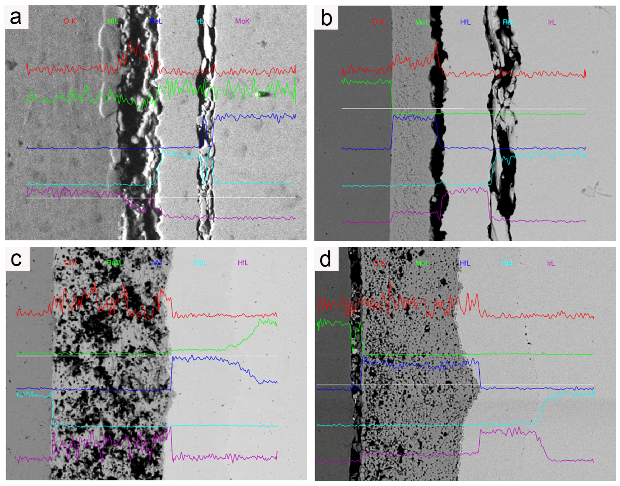
Figure 11 displays the degrees of Mo diffusion and Ir/Re interdiffusion in the composite after treatment at 1800 °C for various durations.
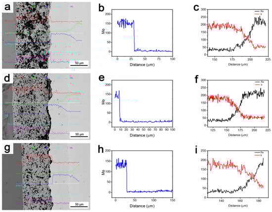
Figure 11.
(a–c) Element diffusion in the composite after it was subjected to 1800 °C for 3 h; (d–f) element diffusion in the composite after it was subjected to 1800 °C for 4 h; (g–i) element diffusion in the composite after it was subjected to 1800 °C for 5 h.
As observed, the long-duration heat treatment was beneficial in terms of improving the binding strength of the layers in the composite. However, it also resulted in an increase in Ir/Re interdiffusion, an increase in the thickness of the diffusion layer between the Ir and Re layers, and the formation of an increased number of Kirkendall voids between these layers. Despite this, the increase in heat treatment duration did not have a significant negative effect on the barrier function of the HfO2 layer for element diffusion. Additionally, the Mo content in the entire composite coating remained very low and did not undergo significant changes with the increase in heat treatment duration.
4. Conclusions
To prepare HfO2/Ir and HfO2/Ir/Re composite coatings, a high-vacuum degassing process is essential. This process involves gradually increasing the temperature after depositing the HfO2 layer and before applying the Ir layer. It effectively prevents bubbling and cracking in the subsequent preparation stages of these composite coatings.
The HfO2 coating effectively prevents direct contact between Ir and O, reducing the oxidation rate of Ir. Additionally, it seals defects like micropores and cracks that may form during oxidation erosion. This slows down the oxidation failure of Ir.
The HfO2 coating functions as a reliable diffusion barrier. It prevents direct contact between O and the Ir coating and obstructs the diffusion of other elements into the Ir coating.
Increasing the heat treatment duration and temperature enhances the binding strength of the composite coating and its constituent layers. However, it also increases the interdiffusion between the Ir layer and other metal layers.
Author Contributions
Conceptualization, H.C. and J.Z.; methodology, J.Z.; validation, X.W. (Xian Wang) and X.W. (Xingqiang Wang); formal analysis, W.L.; investigation, J.Z. and X.Z. (Xingdong Zhao); resources, Y.W.; data curation, W.L. and X.Z. (Xuxiang Zhang); writing—original draft preparation, J.Z.; writing—review and editing, H.C.; visualization, X.W. (Xian Wang); supervision, C.H.; project administration, H.C.; funding acquisition, H.C. All authors have read and agreed to the published version of the manuscript.
Funding
This research was funded by the National Science Foundation of China (Nos. 52061019 and 51361014), Scientific and Technological Project of Yunan Precious Metals Laboratory (Nos. YPML-2022050214, YPML-2023050225 and YPML-2023050213), and Yunnan Science and Technology Projects (No. 202302AB080021).
Institutional Review Board Statement
Not applicable.
Informed Consent Statement
Not applicable.
Data Availability Statement
Data are contained within the article.
Conflicts of Interest
The authors declare no conflict of interest.
References
- Schütze, M. Fundamentals of High Temperature Corrosion. In Materials Science and Technology: A Comprehensive Treatment; John Wiley & Sons, Ltd.: Hoboken, NJ, USA, 2000; pp. 67–130. ISBN 978-3-527-61930-6. [Google Scholar]
- Thakare, J.G.; Pandey, C.; Mahapatra, M.M.; Mulik, R.S. Thermal Barrier Coatings—A State of the Art Review. Met. Mater. Int. 2021, 27, 1947–1968. [Google Scholar] [CrossRef]
- Biaglow, J. High Temperature Rhenium Material Properties. In 34th AIAA/ASME/SAE/ASEE Joint Propulsion Conference and Exhibit; American Institute of Aeronautics and Astronautics: Washington, DC, USA, 1998. [Google Scholar]
- Liu, C.; Chen, J.; Han, H.; Wang, Y.; Zhang, Z. A Long Duration and High Reliability Liquid Apogee Engine for Satellites. Acta Astronaut. 2004, 55, 401–408. [Google Scholar] [CrossRef]
- Guo, Y.; Xie, H.Y.; Jiang, Z.R.; Xia, Z.X. Mechanical Properties and Thermal Shock Resistance of Rhenium Coating in Iridium/Rhenium/Carbon-Carbon Composites. Procedia Eng. 2015, 99, 1407–1414. [Google Scholar] [CrossRef]
- Jacobson, N.S.; Myers, D.L.; Zhu, D.; Humphrey, D.L. Rhenium/Oxygen Interactions at Elevated Temperatures. Oxid. Met. 2001, 55, 471–480. [Google Scholar] [CrossRef]
- Mumtaz, K.; Echigoya, J.; Taya, M. Preliminary Study of Iridium Coating on Carbon/Carbon Composites. J. Mater. Sci. 1993, 28, 5521–5527. [Google Scholar] [CrossRef]
- Davis, J.R. ASM Specialty Handbook: Heat-Resistant Materials; ASM International: Materials Park, OH, USA, 1997; ISBN 978-0-87170-596-9. [Google Scholar]
- Hu, H.B.; Chen, H.Y.; Yan, Y.; Zhang, F.; Yin, J.H.; Zheng, D. Investigation of Chemical Kinetic Model for Hypergolic Propellant of Monomethylhydrazine and Nitrogen Tetroxide. J. Energy Resour. Technol. 2020, 143, 062304. [Google Scholar] [CrossRef]
- Osmont, A.; Catoire, L.; Klapötke, T.M.; Vaghjiani, G.L.; Swihart, M.T. Thermochemistry of Species Potentially Formed During NTO/MMH Hypergolic Ignition. Propellants Explos. Pyrotech. 2008, 33, 209–212. [Google Scholar] [CrossRef]
- Chang, Y.-P.; Boyer, E.; Kuo, K.K. Combustion Behavior and Flame Structure of XM46 Liquid Propellant. J. Propuls. Power 2001, 17, 800–808. [Google Scholar] [CrossRef]
- Wang, X.; Zhao, C.; Huang, H.; Fang, J. Design and Performance Evaluation of a Novel H2/O2 Electro-Chemical Hybrid Thruster. Proc. Inst. Mech. Eng. Part G J. Aerosp. Eng. 2023, 237, 2594–2601. [Google Scholar] [CrossRef]
- Betti, B.; Bianchi, D.; Nasuti, F.; Martelli, E. Chemical Reaction Effects on Heat Loads of CH4/O2 and H2/O2 Rockets. AIAA J. 2016, 54, 1693–1703. [Google Scholar] [CrossRef]
- Liu, B.; Liu, Y.; Zhu, C.; Xiang, H.; Chen, H.; Sun, L.; Gao, Y.; Zhou, Y. Advances on Strategies for Searching for next Generation Thermal Barrier Coating Materials. J. Mater. Sci. Technol. 2019, 35, 833–851. [Google Scholar] [CrossRef]
- Chen, Z.; Wu, W.; Cong, X. Oxidation Resistance Coatings of Ir–Zr and Ir by Double Glow Plasma. J. Mater. Sci. Technol. 2014, 30, 268–274. [Google Scholar] [CrossRef]
- Ai, T.; Wang, F.; Feng, X. High-Temperature Oxidation Behavior of Al2O3/TiAl Matrix Composite in Air. Sci. China Ser. E-Technol. Sci. 2009, 52, 1273–1282. [Google Scholar] [CrossRef]
- Zhang, X.; Wang, Y.; Sun, W.; Yang, Y.; Zhang, C.; Ma, Y.; Cui, Y.; Zhao, C.; Wang, L.; Dong, Y.; et al. Microstructure and Properties of Al2O3–ZrO2–Y2O3 Composite Coatings Prepared by Plasma Spraying. J. Therm. Spray Tech. 2020, 29, 967–978. [Google Scholar] [CrossRef]
- Chen, D.; Lu, J.; Sun, C.; Wang, Q.; Ning, X. Microstructure and Thermal Cycling Behavior of Ta2O5 and Y2O3 Co-Doped ZrO2 Coatings. J. Therm. Spray Tech. 2023, 32, 1327–1337. [Google Scholar] [CrossRef]
- Cverna, F.; ASM International (Eds.) ASM Ready Reference. Thermal Properties of Metals; ASM Materials Data Series; ASM International: Materials Park, OH, USA, 2002; ISBN 978-1-68015-944-8. [Google Scholar]
- Baklanova, N.I.; Lozanov, V.V.; Morozova, N.B.; Titov, A.T. The Effect of Heat Treatment on the Tensile Strength of the Iridium-Coated Carbon Fiber. Thin Solid Film. 2015, 578, 148–155. [Google Scholar] [CrossRef]
- Kisi, E.H.; Howard, C.J. Crystal Structures of Zirconia Phases and Their Inter-Relation. Key Eng. Mater. 1998, 153–154, 1–36. [Google Scholar] [CrossRef]
- Johnson, B.; Jones, J.L. Structures, Phase Equilibria, and Properties of HfO2. In Ferroelectricity in Doped Hafnium Oxide: Materials, Properties and Devices; Schroeder, U., Hwang, C.S., Funakubo, H., Eds.; Woodhead Publishing Series in Electronic and Optical Materials; Woodhead Publishing: Cambridge, UK, 2019; pp. 25–45. ISBN 978-0-08-102430-0. [Google Scholar]
- Alper, A.M. High Temperature Oxides: Oxides of Rare Earths, Titanium, Zirconium, Hafnium, Niobium and Tantalum; Elsevier: Amsterdam, The Netherlands, 2013; ISBN 978-1-4832-7139-2. [Google Scholar]
- Mergia, K.; Liedtke, V.; Speliotis, T.; Apostolopoulos, G.; Messoloras, S. Thermo-Mechanical Behaviour of HfO2 Coatings for Aerospace Applications. Adv. Mater. Res. 2009, 59, 87–91. [Google Scholar] [CrossRef]
- Kasajima, M.; Akashi, T.; Shimada, S. Effect of HfO2 Coating Films on Oxidation Resistance of SiC Ceramics. Key Eng. Mater. 2009, 403, 193–196. [Google Scholar] [CrossRef]
- Bi, M.; Zhu, J.; Luo, Y.; Cai, H.; Li, X.; Wang, X.; Wei, Y.; Wang, X.; Hu, C.; Hu, J.; et al. Effect of Deposition Temperature on the Surface, Structural, and Mechanical Properties of HfO2 Using Chemical Vapor Deposition (CVD). Coatings 2022, 12, 1731. [Google Scholar] [CrossRef]
- McGinn, P.J. Thin-Film Processing Routes for Combinatorial Materials Investigations—A Review. ACS Comb. Sci. 2019, 21, 501–515. [Google Scholar] [CrossRef]
- Abdul Hadi, S.; Humood, K.M.; Abi Jaoude, M.; Abunahla, H.; Shehhi, H.F.A.; Mohammad, B. Bipolar Cu/HfO2/P++ Si Memristors by Sol-Gel Spin Coating Method and Their Application to Environmental Sensing. Sci. Rep. 2019, 9, 9983. [Google Scholar] [CrossRef]
- Zhang, C.; Divitt, S.; Fan, Q.; Zhu, W.; Agrawal, A.; Lu, Y.; Xu, T.; Lezec, H.J. Low-Loss Metasurface Optics down to the Deep Ultraviolet Region. Light Sci. Appl. 2020, 9, 55. [Google Scholar] [CrossRef]
- McCormack, S.J.; Tseng, K.-P.; Weber, R.J.K.; Kapush, D.; Ushakov, S.V.; Navrotsky, A.; Kriven, W.M. In-Situ Determination of the HfO2–Ta2O5-Temperature Phase Diagram up to 3000 °C. J. Am. Ceram. Soc. 2019, 102, 4848–4861. [Google Scholar] [CrossRef]
- Chaston, B.J.C. The Oxidation of the Platinum Metals: A Descriptive Survey of the Reactions Involved. Platin. Met. Rev. 1975, 19, 135–140. [Google Scholar] [CrossRef]
- Wimber, R.T.; Kraus, H.G. Oxidation of Iridium. Metall. Trans. 1974, 5, 1565–1571. [Google Scholar] [CrossRef]
- Wimber, R.T.; Hills, S.W.; Wahl, N.K.; Tempero, C.R. Kinetics of Evaporation/Oxidation of Iridium. Metall. Trans. A 1977, 8, 193–199. [Google Scholar] [CrossRef]
- Carpenter, J.H. Equilibrium Reaction of Iridium and Oxygen at High Temperatures. J. Less Common Met. 1989, 152, 35–45. [Google Scholar] [CrossRef]
- Yang, W.; Zhang, L.; Hua, Y.; Cheng, L. Thermal Stability of Iridium Coating Prepared by MOCVD. Int. J. Refract. Met. Hard Mater. 2009, 27, 33–36. [Google Scholar] [CrossRef]
- Mumtaz, K.; Echigoya, J.; Enoki, H.; Hirai, T.; Shindo, Y. Thermal Cycling of Iridium Coatings on Isotropic Graphite. J. Mater. Sci. 1995, 30, 465–472. [Google Scholar] [CrossRef]
- Wang, J.M.; Zhang, Z.W.; Xu, Z.H.; Lin, X.; Wu, W.P.; Chen, Z.F. Oxidation of Double Glow Plasma Discharge Coatings of Iridium on Molybdenum for Liquid Fuelled Rocket Motor Casings. Corros. Eng. Sci. Technol. 2011, 46, 732–736. [Google Scholar] [CrossRef]
Disclaimer/Publisher’s Note: The statements, opinions and data contained in all publications are solely those of the individual author(s) and contributor(s) and not of MDPI and/or the editor(s). MDPI and/or the editor(s) disclaim responsibility for any injury to people or property resulting from any ideas, methods, instructions or products referred to in the content. |
© 2024 by the authors. Licensee MDPI, Basel, Switzerland. This article is an open access article distributed under the terms and conditions of the Creative Commons Attribution (CC BY) license (https://creativecommons.org/licenses/by/4.0/).