Abstract
The micro-arc oxidation (MAO) technique was employed to produce calcium phosphate coatings on titanium surfaces using an electrolyte composed of hydroxyapatite and calcium carbonate in an aqueous solution of orthophosphoric acid. The coatings’ morphology and composition were regulated by adjusting electrical parameters, specifically the duty cycle and voltage. This study examined the effects of the duty cycle and voltage during the MAO process on the microstructure and composition of calcium phosphate coatings on VT1–0 titanium substrates. Scanning electron microscopy (SEM) was utilized to analyze the microstructure and thickness of the coatings, while X-ray diffraction (XRD) was employed to determine their phase composition. The findings reveal that the surface morphology of the calcium phosphate coatings transitions from a porous, sponge-like structure to flower-like formations as the duty cycle and voltage increase. A linear increase in the voltage within the applied duty cycles led to a rise in the size of the forming particles of amorphous/crystalline structures containing phases of monetite (CaPO3(OH)), monocalcium phosphate monohydrate (Ca(H2PO4)2·H2O), and calcium pyrophosphate (γ–Ca2P2O7).
1. Introduction
In recent decades, significant research efforts have been dedicated to developing materials for medical applications, especially for dental and orthopedic implants [1,2,3]. Titanium and its alloys are ideal for these purposes due to their outstanding properties, including their high strength, low density, excellent corrosion resistance, and superior biocompatibility [4,5,6,7,8]. However, for implants to effectively interact with the physiological environment of the body, their surfaces must exhibit osteoconductive and osseointegrative properties [9,10]. Surface morphology, composition, hydrophilicity, and roughness are important surface characteristics of implants [11]. Therefore, to improve the biological properties and osteoconductivity of implants, calcium phosphate (CaP) coatings are applied to their surfaces.
Various methods are used to apply CaP coatings, including typical methods such as the sol–gel method [12], plasma spraying [13], electrophoretic deposition [14], micro-arc oxidation (MAO) [15], chemical vapor deposition [16], pulsed laser deposition [17], ion beam deposition [18], magnetron sputtering [19], and sandblasting [20,21], among others. Some researchers [22,23] have proposed a combination of methods for the deposition of CaP coatings. Compared to other surface modification techniques, MAO is highly suitable for depositing a porous bioceramic layer on titanium and its alloys [24]. This is because MAO is a cost-effective, straightforward, and environmentally friendly method for preparing CaP coatings [25]. The MAO process is derived from conventional anodic oxidation [26,27].
The structure and properties of CaP coatings produced via MAO can be controlled by adjusting the electrical parameters of the pulsed current, such as the current duty cycle, current intensity, voltage, and density, pulse frequency, pulse duration, and others. For synthesizing CaP coatings on titanium and its alloys by MAO, aqueous electrolytes containing dissolved compounds of Ca2+ and PO43− elements can be utilized [10,28,29]. Our previous study [30] showed that promising results in terms of obtaining bioactive coatings were obtained by MAO of titanium in phosphoric acid electrolytes with a pH range of approximately 3 to 1.
By adjusting the electrical parameters of the MAO process, high-quality CaP coatings with high biological characteristics can be achieved. In most cases, an increase in voltage leads to an increase in pore size and the appearance of preferred phases of CaP coatings. In [31], CaP coatings were synthesized at different low voltages until 450 V. Han Y. et al. [32] fabricated a hydroxyapatite (HA) layer on a Ti6Al4V alloy using an electrolyte composed of 0.2 M calcium acetate and 0.02 M calcium glycerophosphate at varying voltages (400 V, 430 V, 450 V, and 480 V) over a 20-minute MAO process. The X-ray spectra of the coatings revealed peaks corresponding to the HA phase at an applied voltage of 430 V.
More recently, in studies [33,34,35,36], coatings were obtained under conditions of varying the current duty cycle. Zhou P. et al. [33] analyzed the effects of varying duty cycles (10% and 50%) and oxidation durations (10 and 30 min) on the microstructure and microhardness of the coatings. The results showed that under such conditions, the morphology of the deposited layer changed and the microhardness increased with increasing oxidation time and duty cycle. The authors of [33] studied the impact of current frequency and duty cycle on the morphology, microstructure, and properties of coatings. The coatings obtained at 100 Hz and a 60% duty cycle exhibited a lower porosity and were more compact. At 500 Hz and 1000 Hz current frequencies with higher duty cycles, coatings with enhanced wear resistance were formed. The authors of [35] showed that increasing the duty cycle from 10% to 40% resulted in an increase in coating porosity from 5.85% to 14.38%. According to the results of [36], the coating removed at the 80% duty cycle had a homogeneous surface with lower porosity and greater thickness.
As previously discussed, the composition of the electrolyte and the electrical synthesis parameters are critical in determining the surface morphology, elemental and phase composition, and properties of the CaP coatings on the Ti surface during the MAO process. Most prior research has focused on the influence of the electrolyte composition on the structure and properties of the coatings. However, the relationship between the electrical parameters of the MAO, the formation of structural parameters, and the properties of CaP coatings on pure titanium necessitate further investigation. In this work, a CaP coating was produced using the MAO process on the surface of VT1–0 grade titanium at different duty cycles and current voltages. The morphology, microstructure, and composition of the CaP coating were comprehensively examined.
2. Materials and Methods
2.1. Materials
Cylindrical samples with dimensions of Ø10 × 15 mm and plates measuring 10 mm × 10 mm × 1 mm made of Ti grade VT1–0 (equivalent to Ti grade 2) were used as substrates. The surface preparation of the samples for MAO involved several steps: cutting the cylinder, grinding with abrasive papers of varying grit sizes (120, 320, 600, 1200, 2000, and 2500), and polishing until a mirror-like finish with diamond paste was achieved. The samples were then degreased with hexane and rinsed with distilled water. A thread (M10) was cut on the surface of the sample to connect the sample holder to the conductive clamp. The electrolyte was prepared as a mixture of the following composition: 30% aqueous solution of orthophosphoric acid H3PO4 (grade A, CAS 7664-38-2) + hydroxyapatite (Ca10(PO4)6OH2—60 g/L, CAS 1306-06-5) + calcium carbonate (CaCO3—100 g/L, CAS 471-34-1) [37]. Hydroxyapatite—HA—(Sigma-Aldrich, St. Louis, MA, USA) with a particle size distribution of <5 µm was used. To complete the chemical reactions, the electrolyte was allowed to stand for two days after preparation.
2.2. Micro-Arc Oxidation of Titanium
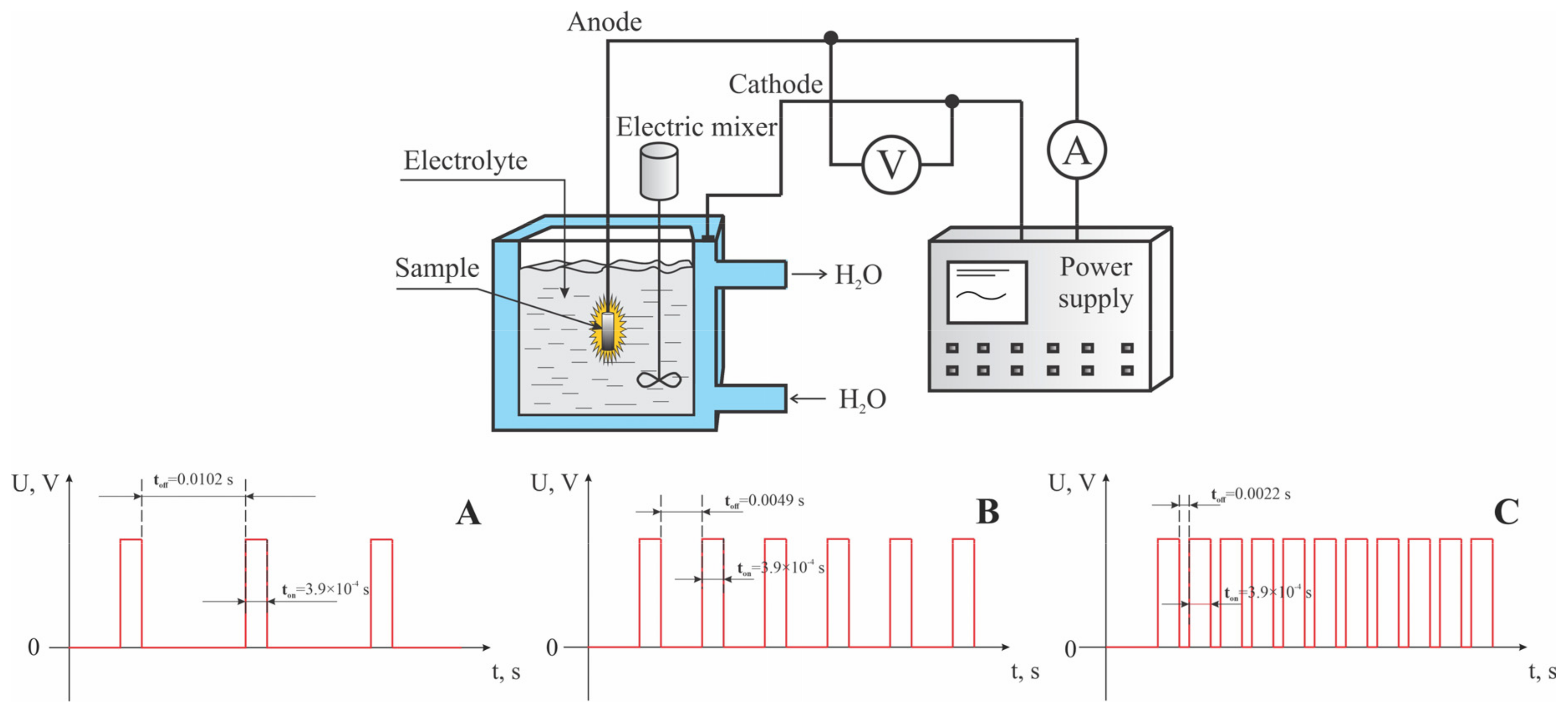
To conduct this study, an experimental setup for micro-arc oxidation was assembled, consisting of a pulsed power source, an electrolytic bath, a water cooling system, an exhaust system, and a pulse recording system. A Stegler 5DT stainless steel ultrasonic bath (Stegler, Sacramento, CA, USA) with a capacity of 5 L and a power of 120 watts served as the cathode and as a vessel for the electrolyte. A custom-designed power supply served as the source of pulsed current, featuring a constant pulse duration of 300 µs. This setup allowed for voltage variations from 0 to 700 V and pause durations of 0.0102, 0.0049, and 0.0022 s, corresponding to duty cycles of 35%, 17.3%, and 8.3%, respectively. The micro-arc oxidation (MAO) process was conducted in the anodic mode, with voltages incrementally increased from 300 to 600 V in steps of 100 V, over a treatment period of 10 min. Three series of experiments were carried out on the surfaces of titanium samples, utilizing different pulse current duty cycles and voltages in the electrolyte solution. A schematic diagram of the pulsed current applied to the electrodes is shown in Figure 1.

Figure 1.
A schematic representation of the micro-arc oxidation (MAO) process, detailing the characteristics of the pulsed electric current applied to the anode under various coating synthesis conditions: (A) for mode A; (B) for mode B; (C) for mode C.
The parameters and names of the samples processed under different modes are listed in Table 1. During the MAO process, the electrolyte in the ultrasonic bath was additionally stirred using a DLS electric stirrer (Velp Scientifica, Monza, Italy). Additional mechanical stirring of the electrolyte during micro-arc oxidation is necessary to ensure even distribution of heat, ions, and additives, prevent particle settling, and remove gas bubbles, thereby ensuring the stability and quality of the process.

Table 1.
Sample designations and MAO parameters.
2.3. Coating Research Methods
Post-MAO samples were subjected to analysis using scanning electron microscopy (SEM) and X-ray diffraction (XRD). The surface morphology, coating thickness, and microanalysis were examined with a JXA-8230 microprobe analyzer (JEOL, Tokyo, Japan) at an accelerating voltage of 25 kV and an electron beam current of up to 8 nA across various magnifications. Microanalysis of all coatings was conducted over an area of 320 × 320 μm2, as well as at various points on each sample across a relatively large area. This paper presents the average results from seven measurements.
An X-ray phase analysis of CaP coatings was performed using a D8 Advance diffractometer (BRUKER, Ettlingen, Germany) with Cu–Kα1 radiation (λ ≈ 1.540598 Å). Data acquisition was performed at a rate of 0.1–1 deg/min; the 2θ angle range was set from 4 to 90 deg with a scan step of 0.01 deg. X-ray diffraction patterns were collected in Bragg–Brentano geometry. Phase analysis was conducted using the PDF 2 release 2023 database. Crystallinity was calculated using “Diffrac. Eva V5.2” software. Quantitative data on the dominant phase peaks were calculated using the Scherrer equation based on the results of the XRD analysis by using “Origin Pro 9.8.0.200”. Origin Pro software automatically determines the full width at half maximum (FWHM) for each diffraction peak.
Tribological tests were conducted using a custom-designed apparatus to measure the friction coefficient (CoF) of samples through reciprocating motion. The testing conditions adhered closely to the DIN 51834-1:2010 standard [38]. The experimental setup comprised a holder for the counter-body with an applied load, a mechanism for sample displacement, an electronic control unit, and a laptop for data acquisition. A 4 mm diameter steel ball, made of SHX15 steel, was utilized as the counter-body. The test parameters were as follows: ball displacement speed of 26 mm/s, friction track length of 5 mm, total friction path length of 5 m, 500 cycles, and applied loads of 5 N and 20 N.
3. Results and Discussion
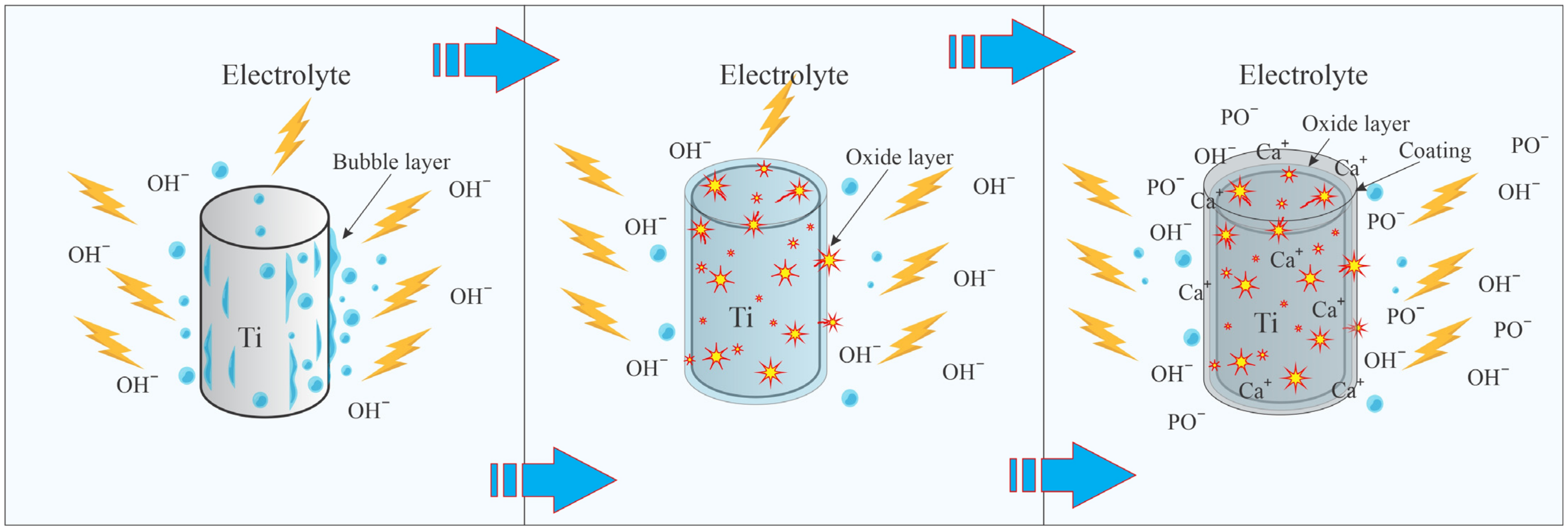
The schematic representation of the MAO process is illustrated in Figure 2. Upon applying voltage to the electrodes, an oxygen layer initiates on the surface of the anode due to electrolysis, which subsequently increases the junction resistance. As a result, an electrical breakdown occurs between the electrode and the electrolyte. Due to the high energy of short-lived plasma discharges, an unstable vapor–gas layer forms on the near-surface layer. At the same time, oxygen bubbles form on the sample surface due to electrolysis, which does not participate in the formation of the oxide layer. Ca+ and PO− ions are formed in the plasma layer and deposited on the titanium surface as calcium phosphate compounds. The deposition process is accompanied by discharges that create microchannels in the deposited layer. In the microchannels, electrolyte anions are attracted by the electric field. Plasma chemical reactions occur in the channels due to extreme temperatures and pressures. Electrolyte ions diffuse towards the anode, where calcium phosphate compounds are synthesized, leading to the formation of the coating. Comprehensive descriptions of the intricate MAO processes are available in the following references [28,39,40].
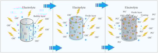
Figure 2.
The main stages of titanium micro-arc oxidation.
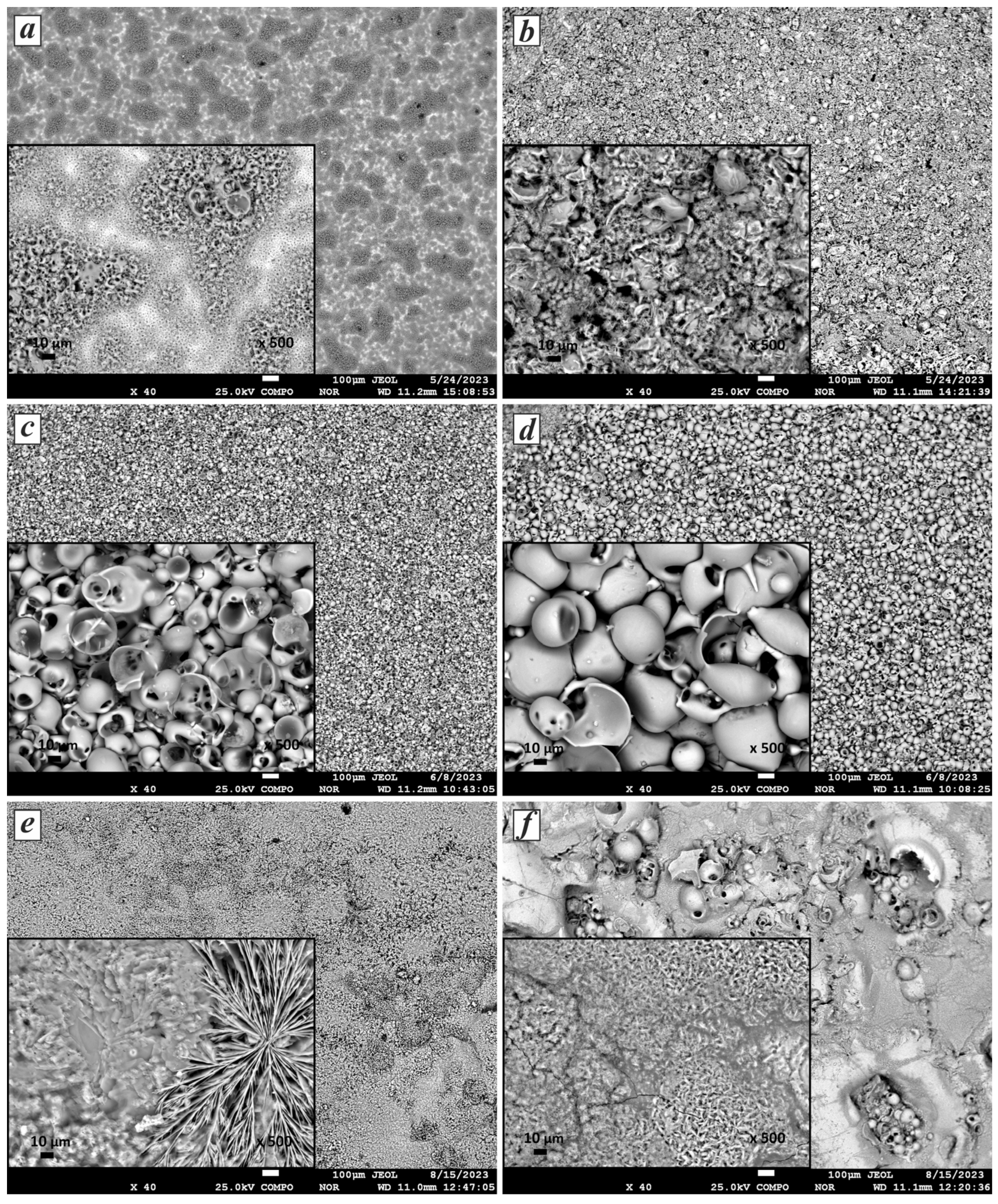
The morphology of the synthesized CaP coatings transforms with variations in the current duty cycle and voltage during the MAO process. Figure 3 presents SEM images illustrating the surface morphology of CaP coatings obtained at 400 V and 600 V across all pulse current modes: A, B, and C. As shown in Figure 3a, at 400 V, a coating with a porous structure is formed, with local areas containing small and large pores. The sizes of the large pores range from 1 to 8 µm, and the small ones range from 0.5 to 2 µm. Upon increasing the voltage to 600 V (Figure 3b), layers with a loose structure composed of fragments of spherical shells filled with needle-like crystals are formed. The length of the needle-like crystals ranges from 1.2 to 6.5 µm. Needle-like and hexagonal columnar CaP coatings exhibit strong adsorption characteristics due to their increased surface area [41].

Figure 3.
SEM images of the morphology of CaP coatings under various conditions: (a) 400 V, mode A; (b) 600 V, mode A; (c) 400 V, mode B; (d) 600 V, mode B; (e) 400 V, mode C; and (f) 600 V, mode C.
On the surfaces of the samples processed under pulse current mode B, CaP coatings are observed with a typical porous sponge-like structure formed by hollow spherical shells (Figure 3c,d). The size of the pores in the spheres increases with increasing current voltage, a result that correlates with previous studies [42,43]. While the average sphere size of the CaP coating obtained at 400 V is 25.7 µm, it increases to 49.9 µm at 600 V. In particular, many studies have shown that pores ranging from 15 to 50 µm promote nutrient cycling [44] in biomaterials for medical implants. In addition, these pores can facilitate bone growth, proliferation, and cell attachment and improve the bond between bone tissue and implants [45].
It is worth noting that in the case of processing under mode C (Figure 3e,f), flower-like structures with a plate-like morphology were formed on the coating surface, with petal thickness ranging from 7 to 86 μm. These structures consist of dendritic crystals growing from a common center in different directions along the coating plane. With increasing MAO time, these crystals spontaneously aggregate into flower-like agglomerates [46]. These structures exhibit significantly higher surface roughness levels [47] and create microstructures or nanostructures that improve the biomedical properties of the implant surface [48]. Flower-like structures during MAO have been reported in previous studies [46,49]. Layers with needle-like and plate-like structures are deposited during MAO at 600 V. However, microcracks are observed in them, which may be related to the high synthesis temperature. The micro-arc discharge may transition to arc discharge under such conditions, resulting in film damage.
Thus, the duty cycle influences the morphology of the resulting coatings more than the other MAO parameters. Meanwhile, the voltage determines the size of the particles formed in the coating. The observed change in morphology from porous structures with needle-like crystals inside hollow spheres to flower-like, plate-like, and dendritic structures with changes in the duty cycle suggests the influence of diffusion in the near-surface layer on the coating formation process. As reported by the authors of [50], the spheroidal structure (Figure 3a–d) results from the electrical breakdown and subsequent surface reconstruction of titanium. Low voltages in mode C lead to the formation of flower-like structures, which also correlates with the results of [49]. Regarding the homogeneity of the coating structures, each image in Figure 3 demonstrates varying levels of homogeneity and surface details at different magnifications, allowing conclusions to be drawn about the quality and characteristics of the coatings. Based on the results, it can be stated that the coatings obtained in mode B, compared to the others, exhibit uniform spherical structures, indicating a high degree of homogeneity. Both images (Figure 3c,d) show spherical particles with a relatively uniform distribution. The homogeneity of the coating contributes to more accurate and reproducible results when using methods for elemental and phase composition analysis.
The elemental analysis of the CaP coatings revealed the presence of calcium (Ca), phosphorus (P), oxygen (O), and titanium (Ti) (Table 2). A significant increase in oxygen content was observed in all samples due to the peculiarities of the MAO method. Based on the Ca/P ratio, it can be inferred that the obtained coatings likely belong to bioresorbable phases. The Ca/P ratio is one of the important indicators of bioactivity. Bioresorbable phases are identified as CaP compounds possessing a lower Ca/P ratio than hydroxyapatite, specifically with a Ca/P ratio of 1.67 or less [30,51]. With a decreasing duty cycle (A→C), the average Ca/P ratio increases from 0.31 to 0.48. It can also be observed that the Ca/P ratio increases with increasing voltage, except in modes A and B 600 V. This may be due to the increased deposition of Ca2+ ions from the electrolyte [52]. A relatively high Ca/P ratio of 0.62 was observed in the CaP layer produced under mode C at 600 V. This elevated ratio is attributed to the presence of the calcium phosphate phase γ–Ca2P2O7, which has a Ca/P ratio of one [53]. An increase in the Ca/P ratio is beneficial for the formation of calcium phosphate and enhances the bioactivity of the coatings. Additionally, as the coating thickness increases, the calcium content rises while the titanium content decreases, as evidenced by the microanalysis results with variations in the duty cycle during the MAO process.
Table 2.
Elemental composition of CaP coatings on titanium and Ca/P ratios.
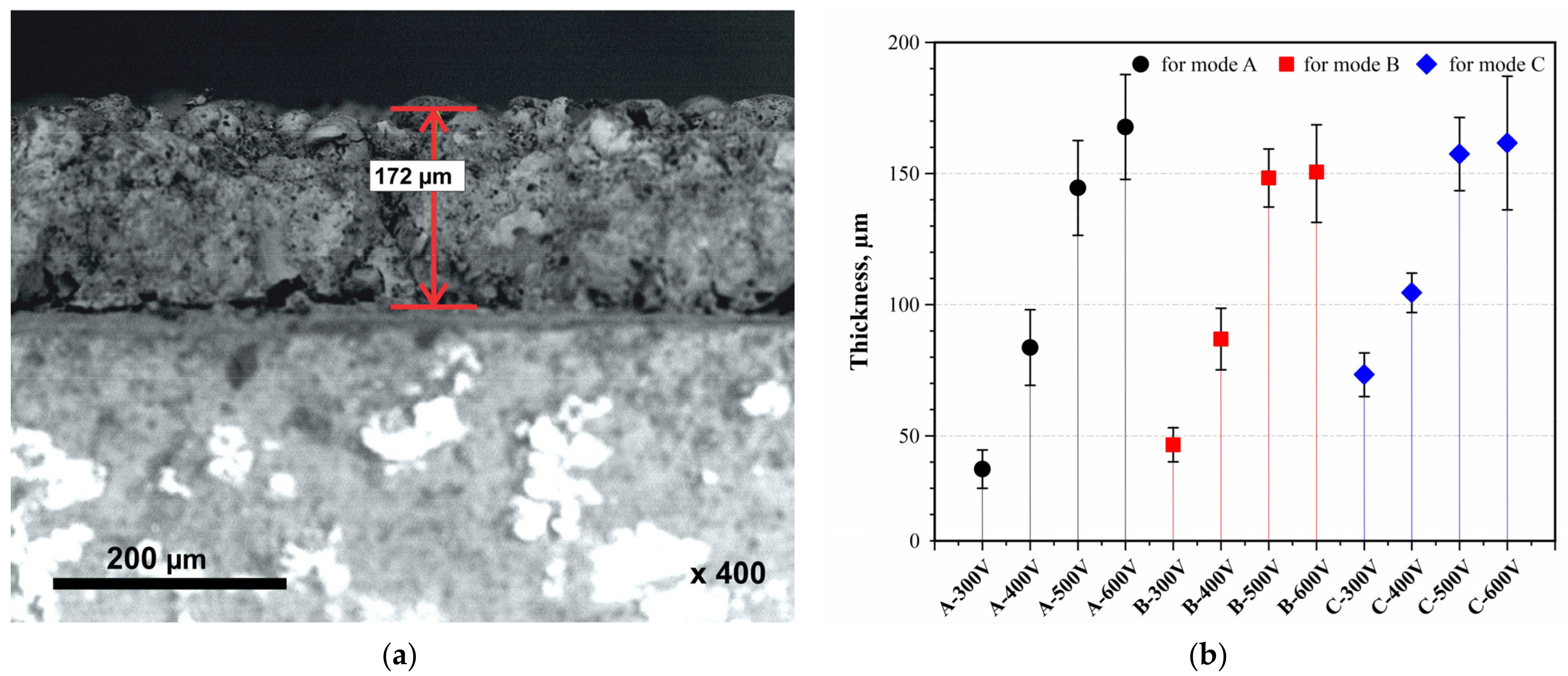
Figure 4 shows the thicknesses of CaP films after MAO in modes A, B, and C at different voltages. It can be observed that the thickness of the coatings increases with both rising voltage and an increased duty cycle. The thickness range for each mode was A from 37.3 to 167.7 µm, B from 46.6 to 150 µm, and C from 73.3 to 161.6 µm. Clearly, the thickness of the films increases with the number of pulses (A→C). However, increasing the MAO voltage to 500 V and beyond induces a transition from micro-arc discharges to arc discharges, resulting in the melting and degradation of the coating, thereby slowing its growth rate. The SEM image shows the structure of the coating formed under mode A at a voltage of 600 V, with a thickness of 172 µm.
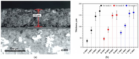
Figure 4.
Structure and thickness of the coating: (a) SEM image of the cross-section (A–600 V); (b) thickness of all obtained CaP coatings.
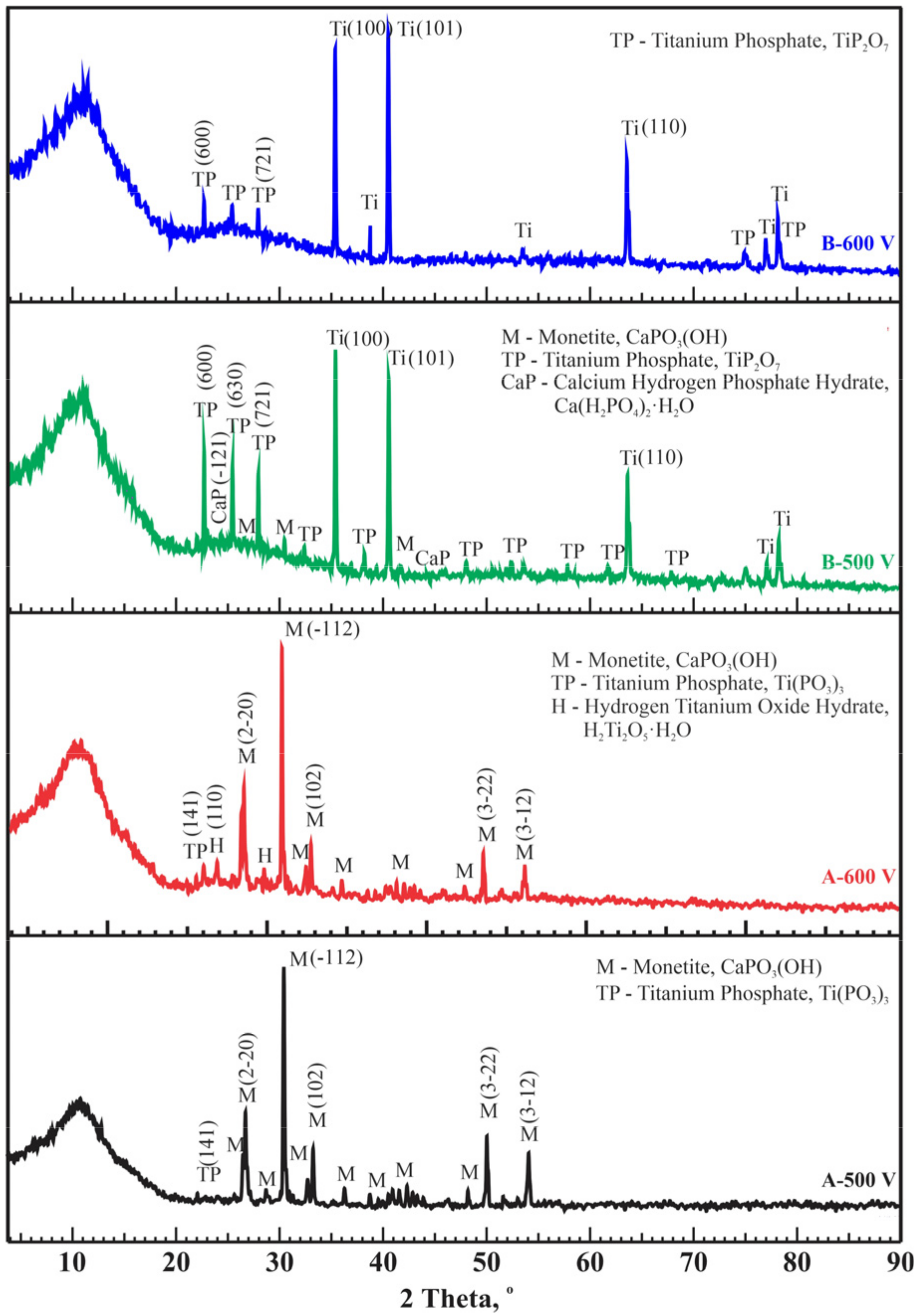
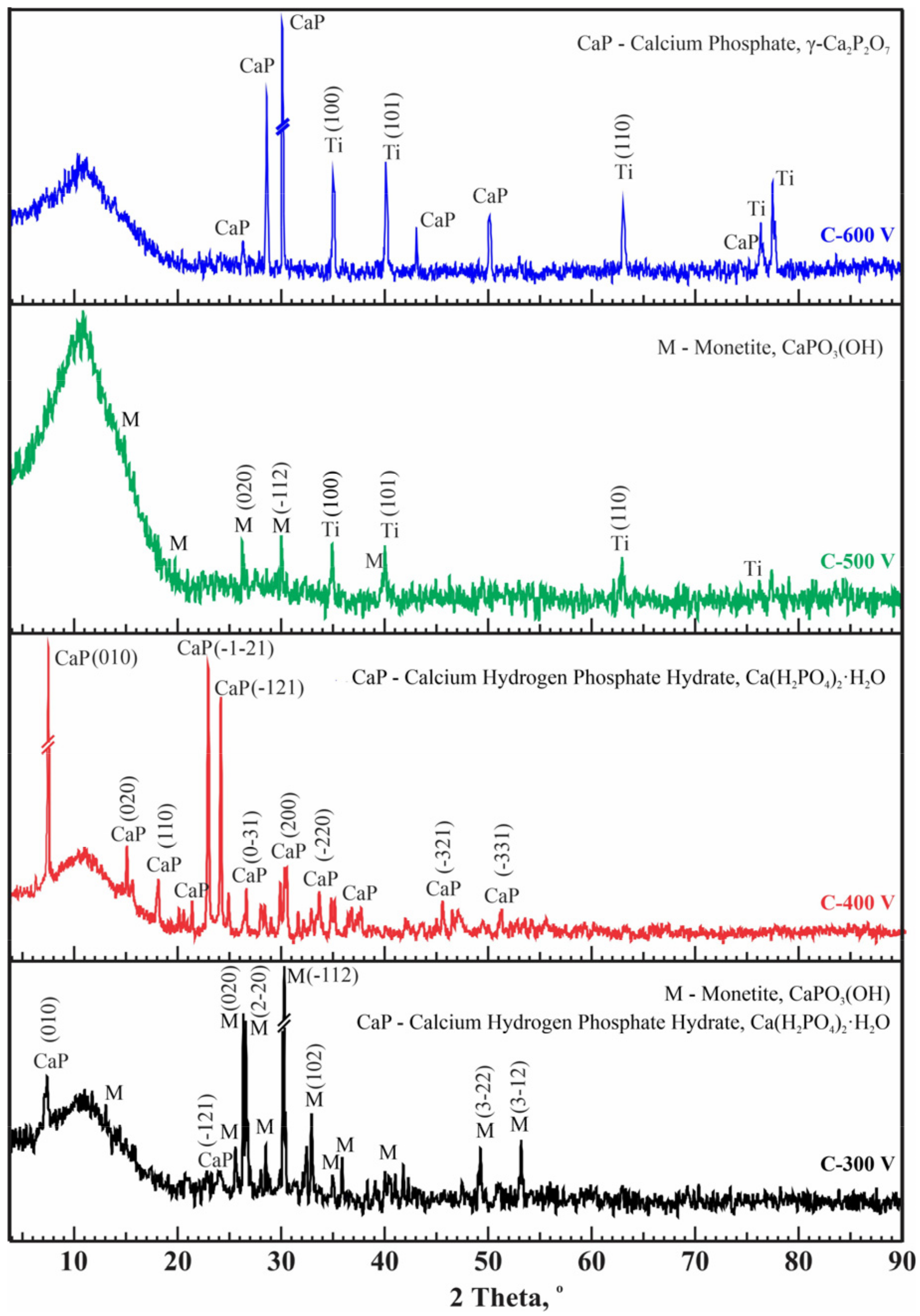
X-ray phase analysis of coatings obtained under modes A and B at high voltages revealed the presence of crystalline phases such as CaPO3(OH) (PDF 00-009-0080), Ca(H2PO4)2·H2O (PDF 00-009-0347), titanium phosphates TiP2O7 (PDF 00-038-1468), Ti(PO3)3 (PDF 00-082-1178), H2Ti2O5·H2O (PDF 00-047-0124), and Ti (PDF 01-086-2608). In coatings obtained at low voltages of 300 and 400 V under modes A and B, peaks corresponding to crystalline phases were absent. In all the diffraction patterns in Figure 5, the amorphous halo of the coating is noticeable. Therefore, we assume that these coatings are in an amorphous state. The presence of an amorphous phase and the slightly soluble crystalline phase monetite (CaPO3(OH)) in the CaP coatings suggests a high bioresorption rate [54,55]. Additionally, monetite facilitates the formation and growth of bone apatite, followed by subsequent mineralization [55]. According to literature data, the main phase Ca(H2PO4)2(H2O) is biocompatible [56,57]. The mechanism of titanium phosphate formation in samples deposited by MAO with varying pulse current duty cycles involves the interaction of titanium with phosphate ions in the electrolyte, driven by localized high temperatures and electric fields generated during the process. Titanium phosphates can form due to the high local temperatures and electric fields on the titanium surface, which initiate and sustain chemical reactions between titanium and phosphate ions (PO₄3−) [58,59]. Varying the pulse current duty cycle affects the duration and intensity of micro-arc discharges, which, in turn, alters the local temperatures and current densities on the titanium surface [33,40]. This enables the regulation of titanium oxidation and the formation of phosphate compounds, influencing the final phase composition and structure of the coating. Thus, in modes A and B, titanium phosphates are formed, whereas in mode C, they are not formed.
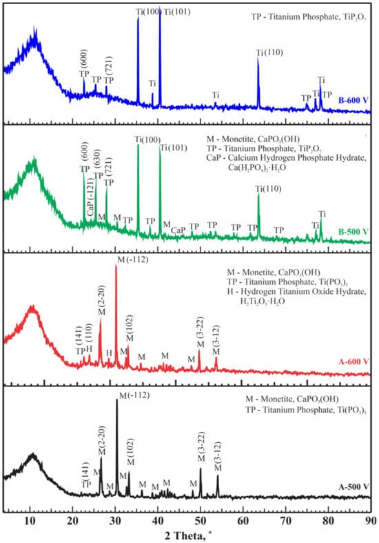
Figure 5.
Diffraction patterns of CaP coatings on Ti obtained at different conditions (modes A and B).
X-ray phase analysis revealed changes in the structural phase composition of CaP coatings with variations in applied voltage under mode C (Figure 6). All coatings exhibit a predominantly X-ray amorphous state. In coatings formed at voltages of 300 and 500 V, the main phase is the same monetite CaPO3(OH). At oxidation at a voltage of 500 V, the coating had monophasic Ca(H2PO4)2(H2O). However, increasing the voltage to 600 V causes the temperature in the discharge channels to rise, which can lead to the formation of the CaP crystalline phase γ–Ca2P2O7 (PDF 00-017-0499). The Ca2P2O7 phase is also biocompatible for use in the production of CaP ceramics for the treatment of bone defects [53,60,61].

Figure 6.
Diffraction patterns of CaP coatings on Ti obtained at different conditions (mode C).
Phase formation does not change significantly with current duty cycles; however, in mode C, CaP compounds were formed without titanium phosphates, and crystalline phases were formed at all processing voltages. For modes A and B, increasing the current voltage to 500 V and above led to the formation of crystalline CaP phases. Table 3 provides the X-ray phase analysis results, detailing the phase fractions of all samples obtained under modes A, B, and C. The presented results for determining the crystallinity-to-amorphous ratio pertain to the crystalline portion of the entire analyzed sample. Obviously, some samples contain titanium from the substrate in the crystalline part. The CaP coatings obtained in mode C show relatively high crystallinity values up to 60.3%.
Table 3.
Crystalline phase composition of the samples with their crystallinity degree.
For X-ray quantitative analysis, the dominant phase of calcium phosphate in the obtained CaP coatings was selected for each sample. Consequently, the informative range included reflections within 4–90° 2θ using copper radiation. The coatings’ quantitative data are presented in Table 4, which lists the average crystallite sizes of the dominant calcium phosphate phase. The crystallite sizes in the crystalline portion of the MAO coating range from 123 to 355 nm. The duty cycles of modes A and B facilitate the formation of CaP coatings with smaller crystallite sizes compared to mode C. The average crystallite size for the B–600 V sample was not determined due to the amorphous nature of the diffraction peaks of the calcium phosphate component of the coating. This also applies to samples processed in modes A and B of micro-arc oxidation at voltages of 300 and 400 V.
Table 4.
Average crystallite size of the dominant CaP crystalline phase of the samples.
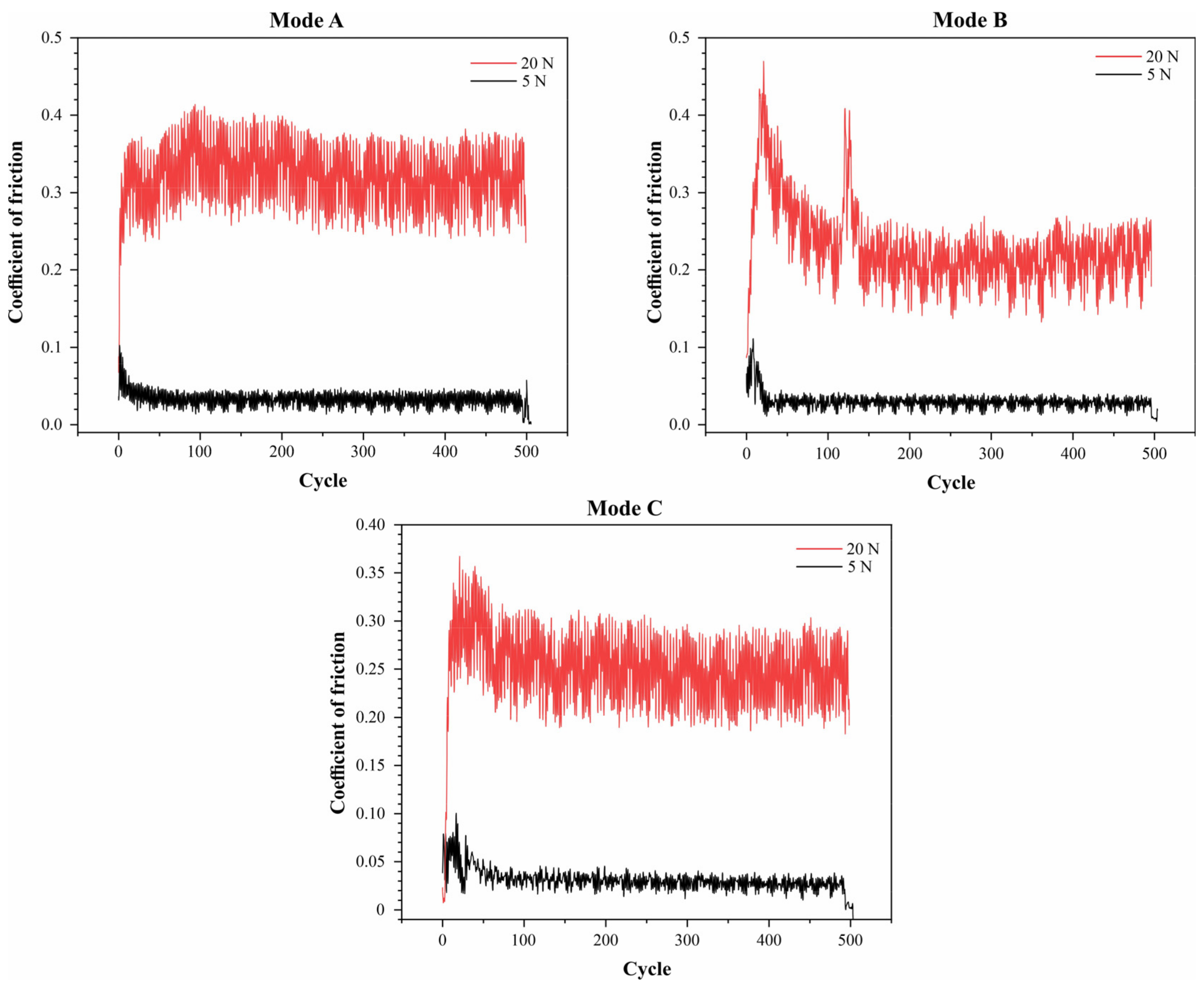
The graphs (Figure 7) show the dependence of the friction coefficient on the number of cycles for three different testing modes under two different loads: 5 N and 20 N. The graphs demonstrate that the friction coefficient is significantly influenced by both the load and the testing mode. Under a load of 5 N, all three modes exhibit a stable friction coefficient at approximately 0.1, 0.1, and 0.05 for modes A, B, and C, respectively. Under a load of 20 N, higher and more variable friction coefficients are observed: modes A and C display consistently high values around 0.35 and 0.25, respectively, while in mode B, the friction coefficient decreases from 0.45 to 0.2 after an initial period.

Figure 7.
Friction coefficient graphs for CaP coatings deposited in duty cycle modes: A, B, and C.
At a load of 5 N, the average wear track width was approximately 150 μm in mode B, while in Modes A and C, the wear track widths were 300 μm and 200 μm, respectively. Under a load of 20 N, the wear track width in mode C was approximately 700 μm, whereas modes A and B showed wear track widths of 520 μm and 460 μm, respectively. These data indicate that mode B is optimal for minimizing wear and the friction coefficient at lower loads, while at higher loads, no mode shows clear advantages.
These findings suggest that both the testing mode and the load significantly influence the antifriction properties of the materials.
4. Conclusions
Based on the results of the experimental studies, the following conclusions can be drawn:
- Calcium phosphate coatings were successfully deposited on a titanium substrate using the micro-arc oxidation method at different duty cycles and voltages in an aqueous solution of orthophosphoric acid with hydroxyapatite and calcium carbonate.
- The linear increase in voltage at the duty cycles used determined the size of the particles formed in the coating. Morphological analysis of the coatings showed that the morphology changes depending on the duty cycles, ranging from sponge-like with needles to flower-like structures.
- Using different duty cycles of micro-arc treatment, amorphous/crystalline structures were formed containing phases such as CaPO3(OH), Ca(H2PO4)2·H2O, and γ–Ca2P2O7, which are biocompatible phases.
- Regarding the crystallinity of the calcium phosphate coatings and the Ca/P ratio, the duty cycle of mode C allowed us to obtain coatings with relatively high indicators: crystallinity up to 60.3% and Ca/P ratio up to 0.62.
Author Contributions
Conceptualization, A.M. and A.P.; methodology, A.K. and N.B.; software, A.K.; validation, A.M., A.P., and A.K.; formal analysis, N.B. and N.T.; investigation, A.M., A.P. and A.K.; resources, D.F. and N.T.; data curation, A.K.; writing—original draft preparation, A.K.; writing—review and editing, D.F. and N.B.; visualization, A.K. and A.P.; supervision, R.A.; project administration, A.M.; funding acquisition, R.A. All authors have read and agreed to the published version of the manuscript.
Funding
This research was funded by the Committee of Science of the Ministry of Education and Science of the Republic of Kazakhstan within Program-Targeted Funding, grant number BR18574018.
Institutional Review Board Statement
Not applicable.
Informed Consent Statement
Not applicable.
Data Availability Statement
The data and results presented in this study are available in the article.
Acknowledgments
The authors are grateful to the National Laboratory for Collective Use of Institute of Metallurgy and Ore Beneficiation JSC for the analysis of the samples with the use of electron microscopy and X-ray phase analysis.
Conflicts of Interest
The authors declare no conflicts of interest.
References
- Abdel-Hady Gepreel, M.; Niinomi, M. Biocompatibility of Ti-alloys for long-term implantation. J. Mech. Behav. Biomed. Mater. 2013, 20, 407–415. [Google Scholar] [CrossRef] [PubMed]
- Paital, S.R.; Dahotre, N.B. Calcium phosphate coatings for bio-implant applications: Materials, performance factors, and methodologies. Mater. Sci. Eng. R Rep. 2009, 66, 1–70. [Google Scholar] [CrossRef]
- Heimann, R.B. Structure, properties, and biomedical performance of osteoconductive bioceramic coatings. Surf. Coat. Technol. 2013, 233, 27–38. [Google Scholar] [CrossRef]
- Geetha, M.; Singh, A.K.; Asokamani, R.; Gogia, A.K. Ti based biomaterials, the ultimate choice for orthopaedic implants—A review. Prog. Mater. Sci. 2009, 54, 397–425. [Google Scholar] [CrossRef]
- Alipovna, M.A.; Karaulovich, K.A.; Vladimirovich, P.A.; Zhanuzakovich, A.Z.; Bolatovna, K.B.; Wieleba, W.; Leśniewski, T.; Bakhytuly, N. The study of the tribological properties under high contact pressure conditions of TiN, TiC and TiCN coatings deposited by the magnetron sputtering method on the AISI 304 stainless steel substrate. Mater. Sci.-Pol. 2023, 41, 1–14. [Google Scholar] [CrossRef]
- Kenzhaliyev, B.K. Innovative technologies providing enhancement of non-ferrous, precious, rare and rare earth metals extraction. Kompleks. Ispolz. Miner. Syra = Complex Use Miner. Resour. 2019, 310, 64–75. [Google Scholar] [CrossRef]
- Almagul, U.; Bagdaulet, K.; Murat, O.; Azamat, Y.; Kaysar, K. Investigations of waste sludge of titanium production and its leaching by nitric acid. In Proceedings of the 19th International Multidisciplinary Scientific GeoConference SGEM 2019, Albena, Bulgaria, 30 June–6 July 2019; Volume 19, pp. 861–868. [Google Scholar]
- Ramazanova, Z.; Zamalitdinova, M.; Kovalenko, M. Investigation of the properties of oxide coatings on titanium alloys obtained by plasma electrolytic oxidation. Kompleks. Ispolz. Miner. Syra = Complex Use Miner. Resour. 2022, 321, 5–13. [Google Scholar] [CrossRef]
- Anselme, K. Biomaterials and interface with bone. Osteoporos. Int. 2011, 22, 2037–2042. [Google Scholar] [CrossRef] [PubMed]
- Qadir, M.; Li, Y.; Munir, K.; Wen, C. Calcium Phosphate-Based Composite Coating by Micro-Arc Oxidation (MAO) for Biomedical Application: A Review. Crit. Rev. Solid State Mater. Sci. 2018, 43, 392–416. [Google Scholar] [CrossRef]
- Le Guéhennec, L.; Soueidan, A.; Layrolle, P.; Amouriq, Y. Surface treatments of titanium dental implants for rapid osseointegration. Dent. Mater. 2007, 23, 844–854. [Google Scholar] [CrossRef]
- Wen, C.; Xu, W.; Hu, W.; Hodgson, P. Hydroxyapatite/titania sol–gel coatings on titanium–zirconium alloy for biomedical applications. Acta Biomater. 2007, 3, 403–410. [Google Scholar] [CrossRef] [PubMed]
- van Oirschot, B.A.; Bronkhorst, E.M.; van den Beucken, J.J.; Meijer, G.; Jansen, J.; Junker, R. A systematic review on the long-term success of calcium phosphate plasma-spray-coated dental implants. Odontology 2016, 104, 347–356. [Google Scholar] [CrossRef] [PubMed]
- Albayrak, O.; El-Atwani, O.; Altintas, S. Hydroxyapatite coating on titanium substrate by electrophoretic deposition method: Effects of titanium dioxide inner layer on adhesion strength and hydroxyapatite decomposition. Surf. Coat. Technol. 2008, 202, 2482–2487. [Google Scholar] [CrossRef]
- Sukhodub, L.F.; Pogrebnjak, A.D.; Sukhodub, L.B.; Sagidugumar, A.; Kistaubayeva, A.S.; Savitskaya, I.S.; Turlybekuly, A. Antibacterial and physical characteristics of silver-loaded hydroxyapatite/alginate composites. Funct. Compos. Struct. 2021, 3, 045010. [Google Scholar] [CrossRef]
- Piccirillo, C.; Denis, C.; Pullar, R.; Binions, R.; Parkin, I.; Darr, J.; Castro, P. Aerosol assisted chemical vapour deposition of hydroxyapatite-embedded titanium dioxide composite thin films. J. Photcohem. Phobiol. A Chem. 2017, 332, 45–53. [Google Scholar] [CrossRef]
- Nishikawa, H.; Hasegawa, T.; Miyake, A.; Tashiro, Y.; Hashimoto, Y.; Blank, D.H.; Rijnders, G. Relationship between the Ca/P ratio of hydroxyapatite thin films and the spatial energy distribution of the ablation laser in pulsed laser deposition. Mater. Lett. 2016, 165, 95–98. [Google Scholar] [CrossRef]
- Feng, H.; Wang, G.; Wu, G.; Jin, W.; Wu, H.; Chu, P.K. Plasma and ion-beam modification of metallic biomaterials for improved anti-bacterial properties. Surf. Coat. Technol. 2016, 306, 140–146. [Google Scholar] [CrossRef]
- Mamaeva, A.; Kenzhegulov, A.; Kowalewski, P.; Wieleba, W. Investigation of hydroxyapatite-titanium composite properties during heat treatment. Acta Bioeng. Biomech. 2017, 19, 161–169. [Google Scholar] [PubMed]
- Wang, H.; Zhu, R.; Lu, Y.; Xiao, G.; He, K.; Yuan, Y.F. Effect of sandblasting intensity on microstructures and properties of pure titanium micro-arc oxidation coatings in an optimized composite technique. Appl. Surf. Sci. 2014, 292, 204–212. [Google Scholar] [CrossRef]
- Mamaeva, A.A.; Kenzhegulov, A.K.; Panichkin, A.V.; Shah, A. Obtaining hydroxyapatite coatings by mechanochemical interaction. Kompleks. Ispolz. Miner. Syra = Complex Use Miner. Resour. 2020, 314, 76–83. [Google Scholar] [CrossRef]
- Rakhadilov, B.; Baizhan, D. Creation of bioceramic coatings on the surface of Ti–6Al–4V alloy by plasma electrolytic oxidation followed by gas detonation spraying. Coatings 2021, 11, 1433. [Google Scholar] [CrossRef]
- Hwang, I.-J.; Choe, H.-C. Surface morphology and cell behavior of Zn-coated Ti–6Al–4V alloy by RF-sputtering after PEO-treatment. Surf. Coat. Technol. 2019, 361, 386–395. [Google Scholar] [CrossRef]
- Wang, Y.; Yu, H.; Chen, C.; Zhao, Z. Review of the biocompatibility of micro-arc oxidation coated titanium alloys. Mater. Des. 2015, 85, 640–652. [Google Scholar] [CrossRef]
- Liu, F.; Song, Y.; Wang, F.; Shimizu, T.; Igarashi, K.; Zhao, L. Formation characterization of hydroxyapatite of titanium by microarc oxidation and hydrothermal treatment. J. Biosci. Bioeng. 2005, 100, 100–104. [Google Scholar] [CrossRef] [PubMed]
- Tian, P.; Xu, D.; Liu, X. Mussel-inspired functionalization of PEO/PCL composite coating on a biodegradable AZ31 magnesium alloy. Colloids Surf. B 2016, 141, 327–337. [Google Scholar] [CrossRef] [PubMed]
- Wang, Z.X.; Zhang, J.W.; Ye, F.; Lv, W.G.; Lu, S.; Sun, L.; Jiang, X.Z. Properties of micro-arc oxidation coating fabricated on magnesium under two steps current-decreasing mode. Front. Mater. 2020, 7, 261. [Google Scholar] [CrossRef]
- Durdu, S.; Deniz, O.F.; Kutbay, I.; Usta, M. Characterization and formation of hydroxyapatite on Ti6Al4 V coated by plasma electrolytic oxidation. J. Alloys Comp. 2013, 551, 422–429. [Google Scholar] [CrossRef]
- Yao, Z.Q.; Ivanisenko, Y.; Diemant, T.; Caron, A.; Chuvilin, A.; Jiang, J.Z.; Valiev, R.Z.; Qi, M.; Fecht, H.J. Synthesis and properties of hydroxyapatite-containing porous titania coating on ultrafine-grained titanium by micro-arc oxidation. Acta Biomater. 2010, 6, 2816–2825. [Google Scholar] [CrossRef] [PubMed]
- Mamaeva, A.A.; Panichkin, A.V.; Kenzhegulov, A.K.; Kalipbekova, M.A. Preparation of calcium phosphate coatings on a titanium substrate under microarc processing conditions. Kompleks. Ispolz. Miner. Syra = Complex Use Miner. Resour. 2017, 2, 33–40. (In Russian) [Google Scholar]
- Song, W.H.; Jun, Y.K.; Han, Y.; Hong, S.H. Biomimetic apatite coatings on micro-arc oxidized titania. Biomaterials 2004, 25, 3341–3349. [Google Scholar] [CrossRef] [PubMed]
- Sun, J.; Han, Y.; Huang, X. Hydroxyapatite coatings prepared by micro-arc oxidation in Ca- and P-containing electrolyte. Surf. Coat. Technol. 2007, 201, 5655–5658. [Google Scholar] [CrossRef]
- Chen, Y.; Zhou, P.; Yuan, M. Effect of Pulse Duty Cycle and Oxidation Time on Microstructure and Properties of Micro-arc Oxidation Coatings on Ti6Al4V Alloy. J. Phys. Conf. Ser. 2023, 2419, 012025. [Google Scholar] [CrossRef]
- Abbas, A.; Kung, H.-P.; Lin, H.-C. Effects of Electrical Parameters on Micro-Arc Oxidation Coatings on Pure Titanium. Micromachines 2023, 14, 1950. [Google Scholar] [CrossRef] [PubMed]
- Tang, Y.; Zhao, X.; Jiang, K.; Chen, J.; Zuo, Y. The influences of duty cycle on the bonding strength of AZ31B magnesium alloy by microarc oxidation treatment. Surf. Coat. Technol. 2010, 205, 1789–1792. [Google Scholar] [CrossRef]
- Hafili, F.; Chaharmahali, R.; Babaei, K.; Fattah-alhosseini, A. Duty cycle influence on the corrosion behavior of coatings created by plasma electrolytic oxidation on AZ31B magnesium alloy in simulated body fluid. Corros. Commun. 2021, 3, 62–70. [Google Scholar] [CrossRef]
- Komarova, E.G.; Sharkeev, Y.P.; Sedelnikova, M.B.; Prosolov, K.A.; Khlusov, I.A.; Prymak, O.; Epple, M. Zn- or Cu-Containing CaP-Based Coatings Formed by Micro-arc Oxidation on Titanium and Ti-40Nb Alloy: Part I–Microstructure, Composition and Properties. Materials 2020, 13, 4116. [Google Scholar] [CrossRef] [PubMed]
- DIN 51834-1:2010-11; Testing of Lubricants—Tribological Test in the Translatory Oscillation Apparatus—Part 1: General Working Principles. German Institute for Standardisation: Berlin, Germany, 2010.
- Wang, X.M.; Zhang, F.Q. Influence of anions in phosphate and tetraborate electrolytes on growth kinetics of microarc oxidation coatings on Ti6Al4V alloy. Trans. Nonferrous Met. Soc. China 2022, 32, 2243–2252. [Google Scholar] [CrossRef]
- Baizhan, D.R.; Rakhadilov, B.K.; Aldabergenova, T.M.; Bayatanova, L.B.; Kurbanbekov, S.R.; Buitkenov, D.B. Obtaining of calcium-phosphate coatings on the titanium surface by micro-arc oxidation. Eurasian Phys. Tech. J. 2023, 20, 34–41. [Google Scholar] [CrossRef]
- Yu, S.; Ling, L.I. Kinetic characteristics of phosphorus adsorption on surface coatings in natural water. Acta Sci. Circumstantiae 2013, 33, 1023–1027. [Google Scholar]
- Soballe, K.; Hansen, E.S.; Rasmussen, H.B.; Jorgensen, P.H.; Beunger, C. Tissue ingrowth into titanium and hydroxyapatite-coated implants during stable and unstable mechanical conditions. J. Orthop. Res. 1992, 10, 285–299. [Google Scholar] [CrossRef] [PubMed]
- Montazeri, M.; Dehghanian, C.; Shokouhfar, M.; Baradaran, A. Investigation of the voltage and time effects on the formation of hydroxyapatite-containing titania prepared by plasma electrolytic oxidation on Ti-6Al-4 V alloy and its corrosion behavior. Appl. Surf. Sci. 2011, 257, 7268–7275. [Google Scholar] [CrossRef]
- Budiraharjo, R.; Neoh, K.G.; Kang, E.T. Hydroxyapatite-coated carboxymethyl chitosan scaffolds for promoting osteoblast and stem cell differentiation. J. Colloid Interf. Sci. 2012, 366, 224–232. [Google Scholar] [CrossRef] [PubMed]
- Han, Y.; Hong, S.H.; Xu, K. Structure and in vitro bioactivity of titania-based films by micro-arc oxidation. Surf. Coat. Technol. 2003, 168, 249–258. [Google Scholar] [CrossRef]
- Liu, S.; Li, B.; Liang, C.; Wang, H.; Qiao, Z. Formation mechanism and adhesive strength of a hydroxyapatite/TiO2 composite coating on a titanium surface prepared by micro-arc oxidation. Appl. Surf. Sci. 2016, 362, 109–114. [Google Scholar] [CrossRef]
- Zhu, W.; Fang, Y.J.; Zheng, H.; Tan, G.; Cheng, H.; Ning, C. Effect of applied voltage on phase components of composite coatings prepared by micro-arc oxidation. Thin Solid Films 2013, 544, 79–82. [Google Scholar] [CrossRef]
- Zhao, L.; Liu, L.; Wu, Z.; Zhang, Y.; Chu, P.K. Effects of micropitted/nanotubular titania topographies on bone mesenchymal stem cell osteogenic differentiation. Biomaterials 2012, 33, 2629–2641. [Google Scholar] [CrossRef] [PubMed]
- Chen, K.T.; Huang, J.W.; Lin, W.T.; Kuo, T.Y.; Chien, C.-S.; Chang, C.-P.; Lin, Y.D. Effects of Micro-Arc Oxidation Discharge Parameters on Formation and Biomedical Properties of Hydroxyapatite-Containing Flower-like Structure Coatings. Materials 2023, 16, 57. [Google Scholar] [CrossRef] [PubMed]
- Wang, X.; Li, B.; Zhou, L.; Ma, J.; Zhang, X.; Li, H.; Liang, C.; Liu, S.; Wang, H. Influence of surface structures on biocompatibility of TiO2/HA coatings prepared by MAO. Mater. Chem. Phys. 2018, 215, 339–345. [Google Scholar] [CrossRef]
- Sheikh, Z.; Najeeb, S.; Khurshid, Z.; Verma, V.; Rashid, H.; Glogauer, M. Biodegradable materials for bone repair and tissue engineering applications. Materials 2015, 8, 5744–5794. [Google Scholar] [CrossRef] [PubMed]
- Du, C.L.; Chen, J.; Cao, B.B.; Xu, L.; Lu, S. Effects of interaction of (NaPO3)6 and NaH2PO4 on Ca/P of MAO Bio-ceramic coating of ZK60 Mg alloy. Mater. Sci. Forum. 2013, 745, 21–27. [Google Scholar] [CrossRef]
- Sauskojus, W.; Wied, J.K.; Litterscheid, C.F.; Mangstl, M.; Schmedt auf der Günne, J. Crystal Structure of γ-Ca2P2O7. Z. Anorg. Allg. Chem. 2022, 648, e202200196. [Google Scholar] [CrossRef]
- Zhou, H.; Yang, L.; Gbureck, U.; Bhaduri, S.B.; Sikder, P. Monetite, an important calcium phosphate compound–Its synthesis, properties and applications in orthopedics. Acta Biomater. 2021, 127, 41–55. [Google Scholar] [CrossRef] [PubMed]
- Lawrence, M.; Jiang, Y. Bio-Aggregates Based Building Materials: State-of-the-Art Report of the RILEM Technical Committee 236-BBM; Springer: Dordrecht, The Netherland, 2017; pp. 39–71. [Google Scholar]
- Seesanong, S.; Seangarun, C.; Boonchom, B.; Sronsri, C.; Laohavisuti, N.; Chaiseeda, K.; Boonmee, W. Recrystallization of triple superphosphate produced from oyster shell waste for agronomic performance and environmental issues. Minerals 2022, 12, 254. [Google Scholar] [CrossRef]
- Boonchom, B.; Danvirutai, C. The morphology and thermal behavior of Calcium dihydrogen phosphate monohydrate (Ca(H2PO4)2•H2O) obtained by a rapid precipitation route at ambient temperature in different media. J. Optoelectron. Biomed. Mater. 2009, 1, 115–123. [Google Scholar]
- Zhao, Z.; Wang, S.; Zhang, J.; Liu, L.; Jiang, L.; Xu, X.; Song, Y. A phosphoric anion layer inhibits electronic current generation and nanotube growth during anodization of titanium. Nanoscale Adv. 2022, 4, 4597–4605. [Google Scholar] [CrossRef] [PubMed]
- Francisca, G.D.O.; Vitoriano, J.D.O.; Alves-Junior, C. Controlling plasma electrolytic oxidation of titanium using current pulses compatible with the duration of microdischarges. Results Mater. 2022, 15, 100310. [Google Scholar]
- Lukić, M.; Stojanović, Z.; Škapin, S.D.; Maček-Kržmanc, M.; Mitrić, M.; Marković, S.; Uskoković, D. Dense fine-grained biphasic calcium phosphate (BCP) bioceramics designed by two-step sintering. J. Eur. Ceram. Soc. 2011, 31, 19–27. [Google Scholar] [CrossRef]
- Khawaja, I.U.; Choudhry, Q.; Mahmood, A.; Gilani, Z.A.; Shahid, S.A.; Farooq, M. Structural, morphological and electrical properties of heat treated CaHPO4 biomaterials. J. Optoelectron. Adv. Mat. 2015, 9, 1171–1175. [Google Scholar]
Disclaimer/Publisher’s Note: The statements, opinions and data contained in all publications are solely those of the individual author(s) and contributor(s) and not of MDPI and/or the editor(s). MDPI and/or the editor(s) disclaim responsibility for any injury to people or property resulting from any ideas, methods, instructions or products referred to in the content. |
© 2024 by the authors. Licensee MDPI, Basel, Switzerland. This article is an open access article distributed under the terms and conditions of the Creative Commons Attribution (CC BY) license (https://creativecommons.org/licenses/by/4.0/).