Abstract
This study presents an innovative dual-layer coating approach integrating titanium dioxide (TiO2) onto diamond-like carbon (DLC)-coated 316L stainless steel. The combination of PECVD-deposited DLC and ALD-deposited TiO2 aims to preserve the inherent tribological properties of DLC while mitigating UV-induced degradation. By leveraging the ability of TiO2 to absorb, reflect, and scatter UV light, this dual-layer strategy significantly enhances the durability of DLC coatings in radiation-prone environments. The effects of accelerated aging through UV exposure on DLC and DLC/TiO2 films were evaluated using an Accelerated Weathering Tester. Comprehensive analyses were conducted to assess the structural and mechanical properties before and after UV exposure, including Raman spectroscopy, profilometry, SEM, EDS, nanoindentation, and tribometry. The results demonstrate that the TiO2 layer effectively mitigates UV-induced damage, preserving the DLC film’s integrity and tribological performance even after 408 h of UV aging. Specifically, the DLC/TiO2 coatings maintained lower roughness, higher hardness, and better adhesion than DLC-only coatings under identical conditions. This research significantly advances protective coating technology by enhancing the durability and performance of DLC films, particularly in aerospace and other demanding industries where exposure to UV radiation is a critical concern.
1. Introduction
Diamond-like carbon (DLC) is renowned for its exceptional hardness and resistance [1], but it is not impervious to challenges. Vulnerabilities may arise in environments characterized by ultraviolet radiation, high altitude, exposure to atomic oxygen, and wide temperature ranges, such as those encountered in high atmospheres or space [2,3,4]. Understanding these changes is crucial when designing materials for radiation-prone environments, as it can cause structural damage to DLC [5]. This is especially true in environments with high radiation doses, where it can lead to hydrogen loss, changes in the concentration of sp3 and sp2 bonded sites, alterations in bond angle disorder, and other effects [6]. These changes compromise the tribological properties of DLC, reducing its wear resistance and increasing friction. The adhesion of DLC to the underlying surface may also be compromised, potentially leading to its flaking or delamination.
Radiation interference can increase wear in scenarios where DLC is a lubricating coating. Additionally, radiation can further induce the formation of structural defects, such as gaps and vacancies in the DLC network, altering its hardness and toughness and increasing roughness [6]. This heightened roughness may render the surface more susceptible to wear and fracture, reducing effectiveness in applications where a smooth surface is crucial [2].
Mitigation strategies, such as using protective layers similar to TiO2, can help preserve DLC properties and enhance its robustness [7]. When applied as an additional layer over DLC, TiO2 plays a significant role in mitigating the effects of ultraviolet radiation [8,9]. The combination of these protective layers creates a more resilient system, preserving the structural integrity of the coating even under prolonged exposure to UV radiation since the TiO2 absorption wavelength is located in the UV region [10], thereby reducing the direct impact on DLC. This effect is attributable to the absorption properties of TiO2 within the UV spectrum, which helps to prevent direct damage to the DLC. It also offers protection against undesirable chemical reactions induced by radiation and enhances tribological properties, providing an additional layer of protection against wear and corrosion [9,11,12].
There are several deposition methods to produce DLC coatings. Among the most commonly employed methods are Physical Vapor Deposition (PVD) and Plasma-Enhanced Chemical Vapor Deposition (PECVD) [1,13,14]. PVD techniques, which include sputtering and cathodic vacuum arc, are renowned for producing high-quality coatings that exhibit superior mechanical and tribological performance [13,15]. However, these techniques necessitate high vacuum environments and elevated temperatures, potentially limiting their applicability to certain substrates and complex geometries [13,16].
In contrast, PECVD offers significant advantages, such as lower deposition temperatures and the capability to coat complex shapes, making it more suitable for a broader range of applications, including those involving flexible and temperature-sensitive substrates [17]. PECVD processes also allow the incorporation of various dopants to fine-tune the properties of DLC coatings, enhancing attributes such as wear resistance, biocompatibility, and corrosion resistance [13,15,16].
Beyond these conventional methods, several non-conventional techniques are gaining traction, driven by the need to meet new market demands in areas such as electronics, biomedical applications, additive manufacturing, and textiles. These techniques, including micro-plasma, dielectric-barrier-discharge (DBD), and electrospray-assisted plasma jet coating, facilitate low-temperature deposition, localized coating, and the ability to coat complex and internal surfaces [13,15].
For example, DBD systems can effectively coat the inner surfaces of narrow tubes, which is challenging with conventional PVD methods. Furthermore, these non-conventional approaches offer scalability for large-area deposition and the integration of nanomaterials for enhanced surface functionalities [13].
Given the specific requirements of the study at hand, PECVD is particularly advantageous. This technique excels in depositing high-quality DLC coatings at relatively low temperatures, with precise control over the coating composition and properties through the use of different precursors and process parameters [17,18]. Moreover, PECVD is well-suited for depositing coatings in large areas, providing a practical solution for the diverse requirements of emerging markets [18,19]. While traditional PECVD requires vacuum conditions, advancements such as Atmospheric Pressure PECVD (AP-PECVD) have made it possible to operate at atmospheric pressures, further simplifying the process and reducing costs, thus making PECVD a cost-effective and versatile method for producing high-performance DLC coatings [13,20].
Various deposition techniques have been developed to produce TiO2 coatings, each with its own set of advantages and challenges. For example, sputtering is a widely used physical vapor deposition technique that offers high adhesion and good control over film thickness and composition. However, it requires sophisticated equipment and can potentially damage the DLC film due to high-energy ion bombardment [10,21]. Chemical Vapor Deposition (CVD) is known for producing uniform films with excellent adhesion that are capable of covering complex geometries. It is extensively used in the microelectronics industry. Nevertheless, CVD processes often require high temperatures [18] and involve hazardous precursor gases, which makes them unsuitable.
Sol-gel techniques are cost-effective, making them suitable for large-area coatings and complex shapes. However, this process may result in films with porosity or cracks, involve long curing times, and require high-temperature annealing to achieve the desired crystalline phases [22]. In contrast to these methods, Atomic Layer Deposition (ALD) stands out for its ability to produce high-quality, uniform thin films with exceptional precision. One of the key advantages of ALD is its capability to deposit films at relatively low temperatures, making it particularly advantageous for temperature-sensitive materials. This method’s self-limiting nature ensures controlled growth for each layer, resulting in excellent film uniformity that is pinhole-free, with controllable thickness and reproducibility [23]. ALD enables atomic-level control over film thickness and composition, ensuring high conformity even on substrates with complex geometries [24,25].
The combination of PECVD and ALD deposition techniques aims to preserve the inherent tribological properties of DLC and also obtain highly uniform, adherent, and conformal dual-layer coatings. This research delves into the synergistic effects of DLC and TiO2, aiming to provide insights into the structural and tribological responses of this composite coating under challenging conditions. By elucidating the vulnerabilities of DLC in UV environments and assessing how TiO2 can serve as a mitigating agent, this study aims to significantly contribute to the advancement of protective coatings with enhanced durability, particularly in aerospace and other demanding industries.
2. Materials and Methods
2.1. Substrate Preparation
Samples of AISI 316L stainless steel were employed for the analyses and studies conducted. Table 1 outlines the key characteristics and properties of the substrate material used.

Table 1.
Properties and characteristics of stainless steel 316L as provided by the supplier.
The substrate material was cut into cylindrical-shaped specimens with a diameter of 20 mm and a thickness of 2 mm. Subsequently, a grinding process was carried out to equalize and level the surface, followed by cleaning to remove residues, salts, and oils, among other contaminants, ensuring the optimal adhesion of the films to the substrate material surface.
The specimens then underwent a meticulous sanding process, progressing through grit sizes #280, #400, #600, #1200, #1500, and #2000, followed by a final polishing step utilizing 0.5 μm aluminum oxide particles.
For thorough cleaning, the material underwent ultrasonic sonication while immersed in a solution of distilled water and enzymatic detergent (B4184Brij® L23 solution—Sigma Aldrich, São Paulo, Brazil) for 15 min. Subsequent rinsing with distilled water was followed by an additional 15 min sonication in acetone. Subsequently, the samples were carefully shielded, securely placed in sample holders, and stored for further use.
2.2. DLC Deposition Process
For the deposition of DLC, a PECVD reactor was employed, comprising a vacuum chamber, voltage source, mechanical and turbo-molecular pump, and flow controllers. The power supply utilized operated at a pulsed DC voltage of 1500 VA. The mechanical vacuum pump (Edwards E2M18—Barueri, São Paulo, Brazil) possessed an operational capacity of 24 m3/h, working in tandem with the high-vacuum turbo-molecular pump (Avaco-Pfeiffer Hipace 300—São Paulo, Brazil), enabling the achievement of an ultimate pressure inside the reactor in the order of 1.3 × 10⁻² Pa.
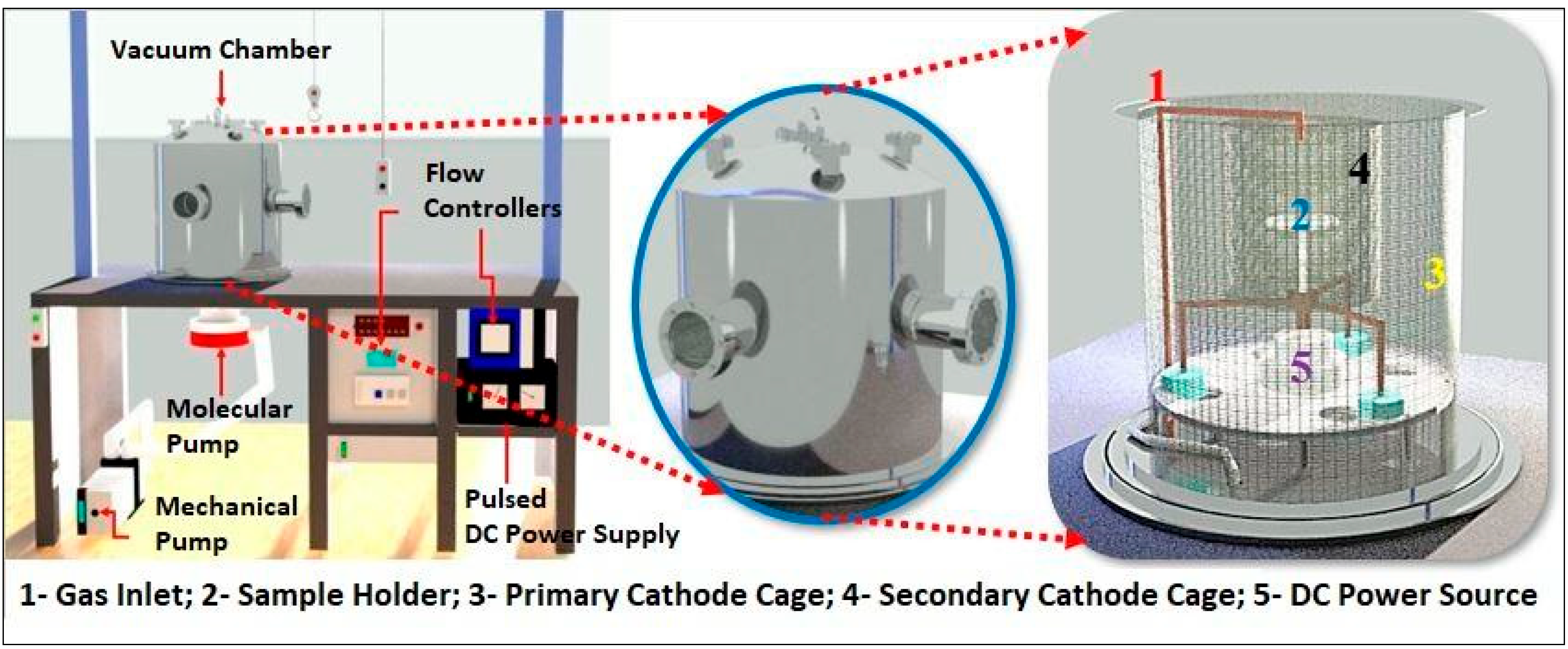
Internally, a primary cathode cage with a diameter of 42.5 cm and a height of 43.5 cm was utilized, along with an additional cathode cage measuring 22 cm in diameter and 25 cm in height. This additional cage, constructed from a woven steel profile, featured 70% transparency and an upper opening of 6 cm in diameter. It was employed to confine ions and densify the plasma over the samples, aiming to achieve enhanced homogeneity and quality of the DLC films. At the reactor base, there was an 8 cm diameter hole for connecting the chamber to the vacuum pump, along with a pressure sensor and a voltage source connector. Gases were introduced through an electronic controllers panel (Avaco-Cole-Parmer—São Paulo, Brazil), calibrated individually for each gas mass flow controller, to manage and control the flow of the injected gases, with a full-scale range of 100 sccm for argon gas, 20 sccm for silane gas (SiH4), and 50 sccm for acetylene gas. Figure 1 illustrates the schematic representation of the utilized reactor.
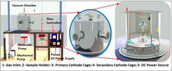
Figure 1.
Representation of PECVD reactor system.
Before deposition, the specimens underwent a 20 min cleaning process employing an argon plasma. In this study, silicon (Si) is used as an intermediate layer between the metal substrate and the DLC coating. This interlayer improves adhesion by forming a strong bond between the metal and carbon layers, thereby enhancing the overall durability and performance of the coating system. This approach ensures that the DLC coating remains securely attached to the metal substrate, even under challenging conditions [26,27]. Acetylene gas (C2H2) was employed as the carbon precursor for the DLC layer. To ensure plasma stability, the transition between gases in different stages was performed gradually. Table 2 outlines the parameters for the DLC coating deposition process stages.
Table 2.
DLC film deposition parameters.
2.3. TiO2 Layer Deposition Process
The deposition of the titanium dioxide (TiO2) film onto the DLC was achieved using the Beneq TFS-200 ALD reactor (Beneq Oy, Espoo, Finland). The reactor was set to operate in thermal mode at 200 °C, completing a total of 1500 reaction cycles. Titanium tetrachloride (TiCl4) was chosen as the precursor, boasting a purity level of 99.94%, while ultrapure water (H2O) served as the oxidizing agent. For the purging process, high-purity nitrogen gas (N2) at 99.99% was employed.
The deposition parameters were carefully configured to minimize the impact of temperature on the DLC film properties. The reaction cycle initiates with a 250 ms pulse of TiCl4, followed by a 2 s purging phase, then another 250 ms pulse of H2O succeeded by an additional 2 s purging phase. The total deposition process lasts approximately one hour and 30 min, followed by 3 h of gradual cooling. Figure 2 provides a visual representation of the reaction cycle employed for the deposition of titanium dioxide through the ALD technique.
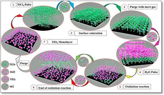
Figure 2.
Representation of TiO2 layer deposition cycle through the ALD technique.
2.4. Films Characterization
2.4.1. Raman Spectroscopy
The obtained films underwent examination using Raman spectroscopy, which was employed to identify carbon phase bands, analyze the displacement and width of characteristic bands, and determine the ID/IG ratio in the tested samples. The analysis was conducted utilizing a Renishaw 2000 system (Caxias do Sul, Brazil), equipped with an argon ion laser (λ = 514 nm) in a backscattering configuration. The laser beam, with a diameter of 2.5 μm, delivered approximately 0.6 mW of power to the sample. Raman shift calibration was performed using the diamond band at 1332 cm−1. All assessments were carried out under ambient conditions at room temperature.
2.4.2. Roughness and Thickness
Both optical and contact profilometers were employed to measure the roughness and thickness of the samples. The optical profilometer, a Wyko NT1100 (Bruker, São Paulo, Brazil) model integrated with Vision 32 software from Bruker, São Paulo, Brazil, was utilized to measure the thickness of DLC-coated samples and the roughness of all samples. The roughness was assessed using both arithmetic roughness (Ra) and quadratic roughness (Rq) parameters. The comparison between Rq and Ra was important to detecting surfaces with random peaks or valleys, as Rq highlights these features more than Ra by squaring the error in the Y direction; due to this, the Rq results give extra weight to high values and are about 11% higher than Ra. On the other hand, the Ra value over a sampling length represents the average roughness. Therefore, if an atypical peak or valley appears on the surface, the average value will not undergo significant alteration, potentially concealing such a defect.
Measurement of the film thickness of the DLC/TiO2 film was conducted using a contact profilometer, specifically the Dektak 150 Veeco model(Bruker, São Paulo, Brazil). Thickness measurements were performed on a silicon sample partially coated with the film.
2.4.3. Adherence Evaluation
The film’s adhesion was assessed following the ASTM C1624 standard [28] for the scratching test. The progressive loading (PL) mode was employed for the film scratching test. A preload force of 0.5 N was applied, and the load force ranged from 0 to 20 N during the test. The horizontal displacement rate was set at 6 mm/min, with a force application rate of 12 N/min, covering a total scratch length of 10 mm. The test was conducted using a Tribometer UMT Bruker Model, São Paulo, SP, Brazil, under a relative humidity of 50% and a temperature of 21 °C. Post-test, the critical scratch load and the type of cracks formed were examined on the scratched track using an optical microscope and, in some cases, SEM. The results were then compared with the literature references and ASTM C1624 standards.
2.4.4. Surface Evaluation
The surfaces of the samples were examined using scanning electron microscopy (SEM) with the ZEISS—EVO MA 10 equipment, São Paulo, SP, Brazil. The samples were scrutinized to assess surface conditions both before and after testing. Energy-dispersive spectroscopy (EDS) was employed to quantify the percentage of elements within the film.
2.4.5. Hardness Evaluation
The ultra-high resolution Nanoindenter UNHT with real force and displacement sensors was used to evaluate the mechanical properties of the tested materials at the nanoscale. Linear loading mode was employed, using a diamond Berkovich indenter (a three-sided pyramid with an area-to-depth function that is the same as that of a Vickers indenter), with a loading and unloading rate of 5 mN/min, a pause of 5 s, and a maximum depth of 100 nm (approximately 10% of the coating thickness). For calculating the hardness and Young’s modulus, Oliver and Pharr’s method was adopted [29,30], and the Poisson’s ratio for a-C:H films was assumed to be 0.3.
2.4.6. UV Light Ageing Test
The QUV Accelerated Weathering Tester was employed to evaluate the effects of accelerated aging through UV exposure on DLC and DLC/TiO2 films deposited onto a 316L stainless steel substrate. The tests followed the ASTM G154 practices [31], where each coating type was placed in the UV test chamber equipped with fluorescent lamps (Irradiance: 0.89 W/m2/nm, wavelength: 320 to 400 nm, and a temperature of 60 °C). The chamber operated on an 8 h on and 4 h off cycle with condensation. Two sets of five samples each underwent testing, accumulating a total of 408 h of exposure. These conditions aimed to assess changes in the properties of the tested materials when exposed to sunlight and moisture, such as rain or dew, in real-world conditions. Subsequently, a thorough inspection and analysis of the samples were conducted to identify any visible changes in color, chalking, cracking, peeling, blistering, fading, and loss of physical properties. SEM and Raman spectroscopy were also employed on the samples before and after the test to compare the surface conditions and changes in the film’s Raman spectra.
3. Results and Discussion
3.1. DLC and TiO2 Chemical Structure
The properties of DLC coatings are intricately tied to the ID/IG ratio, H content, and the shift of the bands D and G [1]. The D band, associated with the disorder, encompasses vibrational modes linked to sp, sp2, and sp3 hybridizations. In contrast, the G band indicates a tangential elongation of the sp2 hybridization mode [32], and its intensity exhibits a direct correlation with the content of sp2 bonds [33]. The ratio of sp3 to sp2 varies considerably as a function of the hydrogen content, which is one of the key factors in increasing the sp3 fraction in hydrogenated DLC (a-C:H) [34,35].
For this study’s samples, a thorough analysis of the Raman spectra was conducted to determine DLC coating characteristics. Each film was analyzed before and after the test to verify the variation in D and G bands, ID/IG ratio, and full width at half maximum of the G band (FWHMG).
The bands D and G vary from 1346 to 1375 and 1539 to 1549 cm−1, and the ID/IG ratio varies from 0.52 to 0.73 for DLC and 0.68 to 0.71 for DLC/TiO2 specimens, as presented in Table 3.
Table 3.
ID/IG ratio, D and G band positions, and FWHM of G bands were measured before testing for DLC and DLC/TiO2 coating surface.
The incorporation of the TiO2 layer via the ALD process resulted in a slight rightward shift in the D band of the DLC films, with no significant change observed in the G band or the ID/IG ratio. The FWHMG, a measure of the disorder [36,37], showed some minor effects due to the ALD deposition process.
The ID/IG ratio, which is directly related to the sp2/sp3 ratio, suggests a higher prevalence of sp2 bonding over sp3 [36]. Additionally, the photoluminescence slope of the DLC Raman spectrum, along with the ID/IG ratio and G band positions, aligns with those of a low-hydrogenated film (<20%), collectively categorizing the DLC films as a-C:H [38]. Moreover, the slight rightward shift in the D band suggests the presence of clusters containing aromatic carbon rings and open-chain carbon bonds within the coatings.
3.2. Results of the UV Ageing Test
Figure 3 presents a comparative analysis of the Raman spectra for DLC/TiO2 and DLC films on an AISI 316L substrate before and after UV exposure.
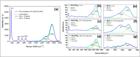
Figure 3.
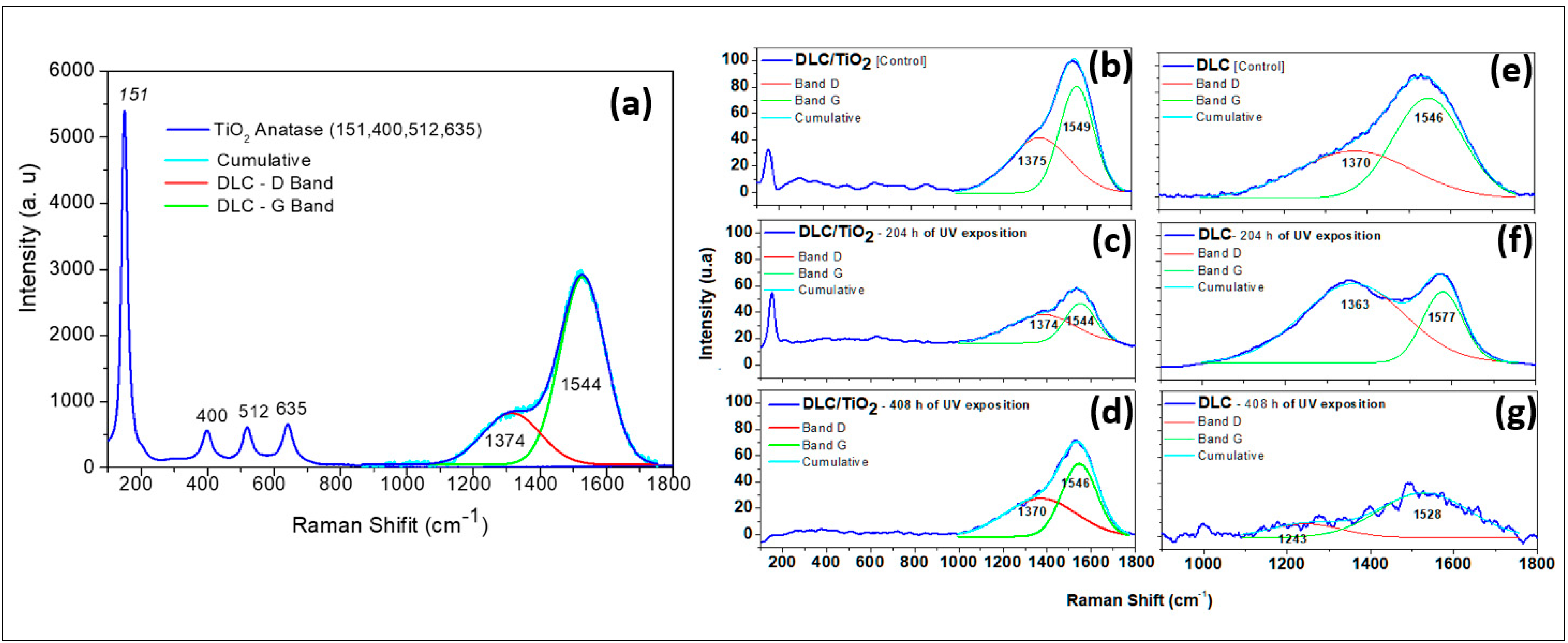
Comparative Raman spectra analysis of DLC/TiO2-film and DLC samples on the AISI 316L substrate before and after UV exposition. (a) DLC/TiO2-film sample characteristic with active Raman modes of the thin anatase phase of TiO2 film deposited on DLC samples; (b) DLC/TiO2-film sample before UV aging test; (c) DLC/TiO2-film sample after 204 h of UV aging test; (d) DLC/TiO2-film sample after 408 h of the UV aging test; (e) DLC sample before the UV aging test; (f) DLC sample after 204 h of the UV aging test; (g) DLC sample after 408 h of the UV aging test.
Figure 3a illustrates the characteristics of the DLC/TiO2 film, highlighting the active Raman modes of the anatase phase deposited on DLC samples. Since the TiO2 film is very thin, the laser penetrates the film and detects both the DLC and TiO2 interlayers. Figure 3b presents the DLC/TiO2-film sample before the UV aging test. Figure 3c and Figure 3d present the spectrum of the DLC/TiO2 film after 204 and 408 h of UV aging, respectively. Figure 3e shows the spectrum of the DLC film before UV aging. Figure 3f and Figure 3g present the spectrum of the DLC film after 204 and 408 h of UV aging, respectively.
The Raman spectra of the studied films were analyzed by fitting them with a Gaussian function, followed by deconvolution of the curves for the D and G bands. To estimate the sp3 hybridization ratio qualitatively, the ID/IG value was calculated from the areas under the D and G bands [39,40,41,42,43,44,45]. When analyzing the Raman spectra of the DLC/TiO2 film after 204 h of UV aging, as shown in Figure 3c, several bands were observed at 143, 399, 519, and 639 cm−1, corresponding to the active Raman modes characteristic of the anatase phase of TiO2 [9]. Additionally, discernible bands at 1374 and 1544 cm−1 correspond to the D and G bands of the DLC film [37,38].
After completing the 408 h UV test cycle, the bands related to the anatase phase of TiO2 are no longer discernible, as shown in Figure 3d. Only the distinctive signature of the DLC film remains, represented by the D and G bands, closely resembling those of the DLC control sample, as shown in Figure 3e. Samples containing only the DLC film exposed to UV radiation exhibited significant variations in their Raman spectra compared with the control sample and those films with the TiO2 layer, indicating continued degradation of the film, as illustrated in Figure 3f,g. Upon closer examination of the DLC film samples after 408 h of UV aging, substantial changes were observed in the DLC Raman spectrum signature, making the identification of the D and G bands challenging.
The values of ID/IG in samples subjected to UV testing, as displayed in Table 4, show significant changes compared with the reference samples in Table 3, accompanied by notable alterations in band shape. During the first 204 h of UV exposure, the values of the ID/IG ratio increased, FWHMG decreased, and band G position had a rightward shift tendency. At the end of the 408 h test period, the ID/IG ratio for DLC films decreased to a lower value compared with the initial and those obtained after 204 h of testing. Additionally, the FWHMG increased, which means that the band is broader, indicating a greater range of frequencies contributing to the band [37]. This broadening can be caused by various factors, such as disorder or defects in the carbon structure [37,46]. There was also a tendency for a leftward shift in the band G position, which indicates a decrease in the wavenumber value at which the band reaches its maximum intensity [37]. This shift can also be associated with changes in the carbon structure, such as an increase in disorder or a shift towards sp2 hybridization [46]. Together, an increased FWHM and a leftward shift in the position of the G band may suggest changes in the carbon structure of the DLC film, potentially indicating a decrease in the diamond-like character and an increase in disorder or defects [36,43,46,47].
Table 4.
ID/IG ratio, D and G band positions, and FWHM of G bands measured after 204 and 408 h of the UV aging testing for DLC and DLC/TiO2 coating surface.
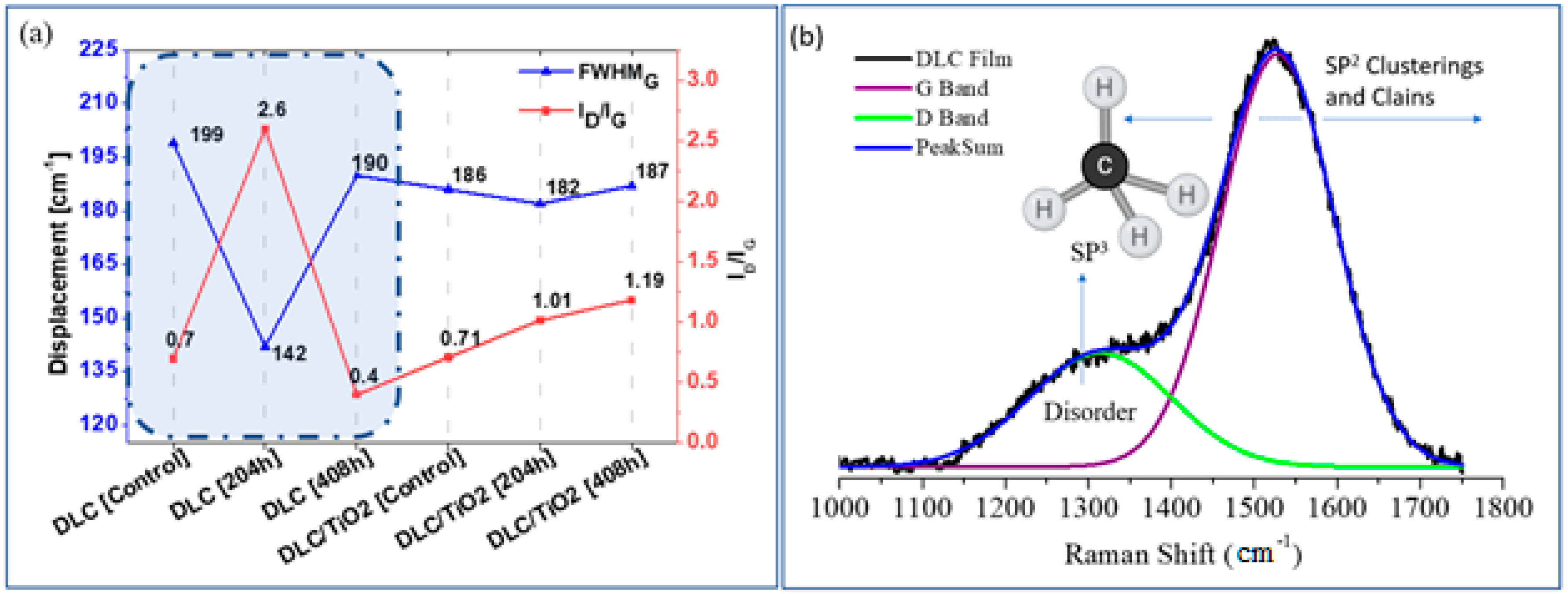
Figure 4a compares the average width of the FWHMG band and the ID/IG ratio variations among the different film samples studied. Figure 4b provides a schematic illustration of the factors influencing the Raman G and D bands of DLC films when using either a 532 nm or 514 nm laser. Robertson J. outlined a method for obtaining detailed bonding structures of DLC films using different laser wavelengths and identified specific polarizable and scattering sites crucial for Raman analysis [35]. Building on Robertson’s work, this study examines the percentage variations of ID/IG ratios and FWHMG for the analyzed film samples. These variations are summarized in Table 5.
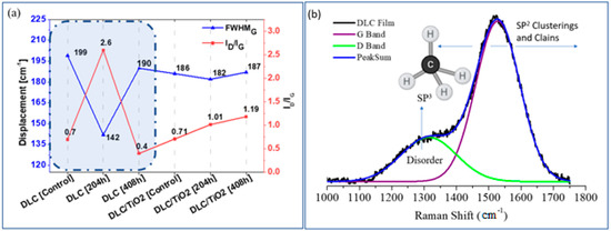
Figure 4.
(a) Comparison of the average FWHMG and ID/IG ratio variation of each studied film sample emphasis was done for DLC samples in blue shading in figure a; (b) Schematic plot of factors that affect the Raman G and D bands of DLC films using a laser of 532 nm or 514 nm.
Table 5.
Percentage variations of ID/IG ratios and FWHMG for DLC and DLC TiO2 after UV exposition.
Comparing the DLC sample before and after 204 h of UV exposure, a 28.64% reduction in FWHMG was observed after 204 h and a 4.52% reduction after 408 h. Conversely, for DLC/TiO2 film, the reductions were 2.15% after 204 h and 0.53% after 408 h of exposure. This suggests that after 204 h, DLC exhibited a narrower band, indicating an enhancement in the graphite phase. Additionally, the increase in ID/IG to 371% after 204 h reveals a transition from amorphous carbon to graphite phase, with a progressive reduction in amorphous phase and the promotion of ordered graphite layers while retaining aromatic small graphite rings.
This indicates a transition from sp3 to sp2 bonding due to hydrogen desorption and graphitization of the DLC structure [48], resulting in a decrease in the sp3 fraction and a reduction in the disorder band [2]. After 408 h, the ID/IG ratio decreased significantly from 2.6 to 0.4, primarily due to the intense degradation of the D band in the DLC film, as shown in Figure 3g. This transition or alteration in the DLC film could potentially lead to complete degradation or mischaracterization, as UV irradiation can cause the breakage of sp3 C-H bonds in a-C:H film. This, in turn, increases the number of dangling bonds in the films and decreases their wear life [49].
In contrast, DLC/TiO2 film showed lower percentage reductions in FWHMG, indicating a minimal reduction in the width of the G band and a low percentage of graphitization. Moreover, the ID/IG ratio remained around 0.7–1.19, which is characteristic of amorphous DLC.
Comparing the film morphology and Raman spectra, it was observed that in the samples with DLC/TiO2 film, there was notable preservation of the DLC structure after 408 h of testing. Only minor changes in the Raman spectra were observed compared with the control sample. However, comparing the Raman spectra after 204 and 408 h of testing revealed the disappearance of bands associated with the anatase phase present at 204 h, indicating some changes occurred in the TiO2 film structure.
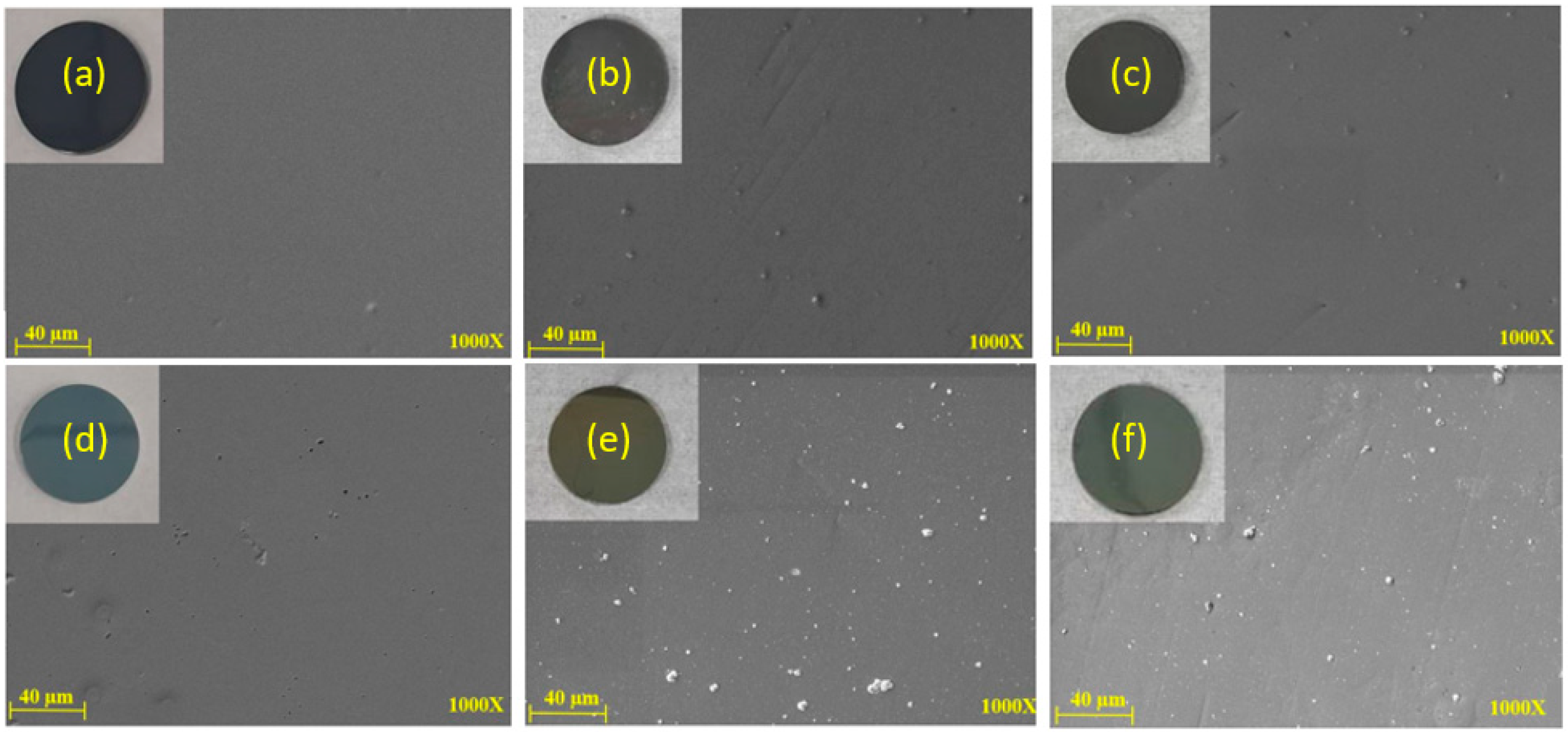
MEV and EDS analyses were also conducted on the samples after 204 and 408 h of UV aging tests for DLC and DLC/TiO2 coating surfaces. Figure 5 displays six SEM images comparing DLC and DLC/TiO2 film samples on an AISI 316L substrate. (a) Shows the DLC film before UV aging, (b) after 204 h of UV exposure, (c) after 408 h of UV exposure, (d) depicts DLC/TiO2 before the UV aging test, (e) after 204 h of UV exposure and (f) after 408 h of UV exposure. Despite progressive changes in film color, no cracking or delamination of the films was observed.
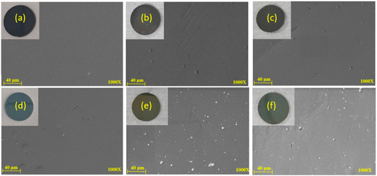
Figure 5.
SEM comparative analyses were conducted on DLC and DLC/TiO2-film samples on the AISI 316L substrate. (a) DLC before the UV aging test; (b) DLC after 204 h of UV exposure; (c) DLC after 408 h of UV exposure; (d) DLC/TiO2 before the UV aging test; (e) DLC/TiO2 after 204 h of UV exposure; (f) DLC/TiO2 after 408 h of UV exposure.
Figure 6 illustrates the comparative EDS analyses: (a) DLC/TiO2 before UV exposure, (b) after 204 h of UV exposure, and (c) after 408 h of UV exposure. Elemental analysis was conducted using Energy Dispersive Spectroscopy (EDS), providing a semi-quantitative assessment of elemental composition. The results revealed the presence of titanium and oxygen in all samples subjected to UV testing for 204 and 408 h. A noticeable decrease in the weight percentage of both elements was observed from 204 to 408 h, using the same analysis area and electron beam intensity for both measurements.
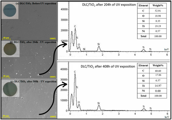
Figure 6.
Comparative EDS analysis on DLC/TiO2-film sample on the AISI 316L substrate. (a) DLC/TiO2 before UV exposure, (b) after 204 h of UV exposure, and (c) after 408 h of UV exposure.
3.3. Film Thickness and Roughness Measurements
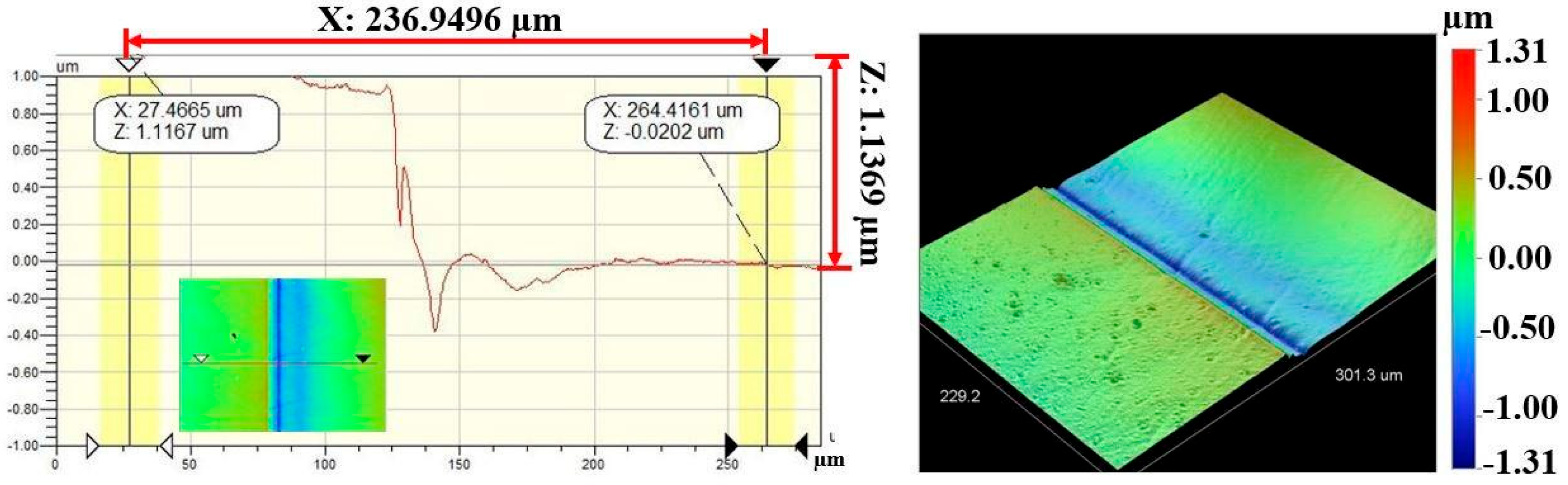
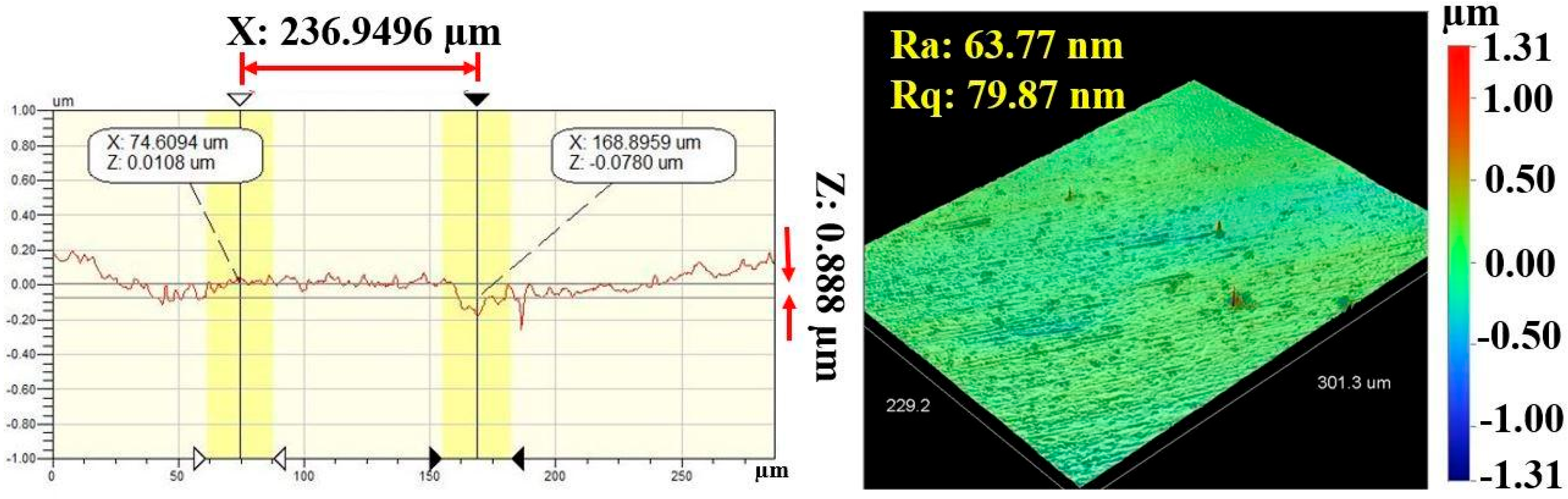
Figure 7 and Figure 8 show the results of profilometry measurements for the thickness and roughness of DLC-film samples on the AISI 316L substrate, respectively. Using the optical profilometer, the measurements were determined from the step heights observed in the line profiles, and the thickness yielded a mean value of 1 µm. The highest roughness values, Ra and Rq, measured from the control sample were 63.77 nm and 79.87 nm, respectively, for a film 1.1369 µm thick, showing a very smooth film.

Figure 7.
Thickness measurement of DLC-film samples on AISI 316L substrate.
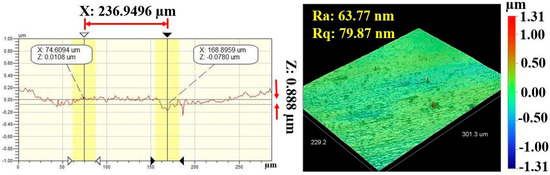
Figure 8.
Roughness values (Ra and Rq) of DLC-film samples on AISI 316L substrate.
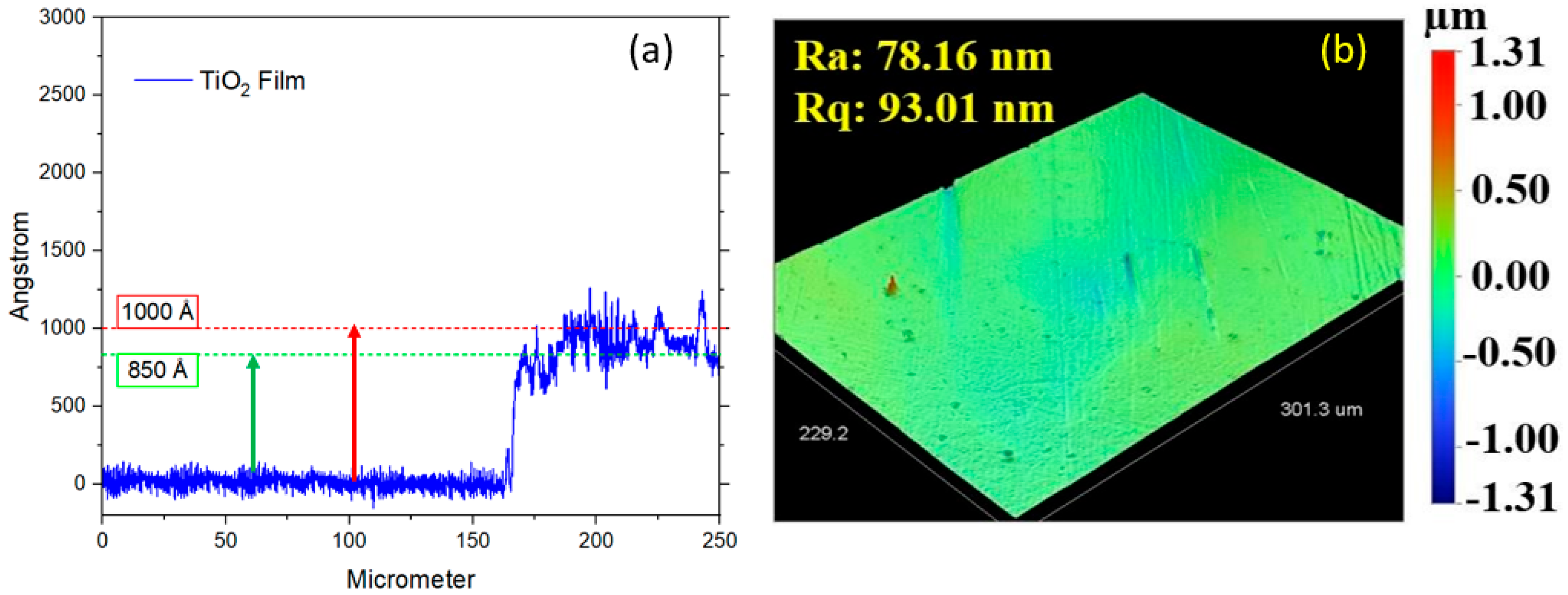
The thickness of the TiO2 layer on the DLC film was measured solely using a contact profilometer on samples with a silicon substrate due to its nanoscale dimensions. The TiO2 thickness ranged from 85 to 100 nm (850 to 1000 Å), as illustrated in Figure 9a, and the roughness is illustrated in Figure 9b. The highest roughness values observed for the DLC/TiO2-film samples on the AISI 316L substrate were 78.16 nm (Ra) and 93.01 nm (Rq). The increased roughness observed in the DLC/TiO2-film samples on the AISI 316L substrate may be attributable to several factors influencing the deposition process.

Figure 9.
(a) Roughness values (Ra and Rq) of DLC/TiO2-film samples on AISI 316L substrate. (b) Thickness measurement of the TiO2 layer on DLC film using a contact profilometer on a silicon substrate.
Variations in deposition conditions, such as temperature, pressure, and precursor concentrations, can lead to non-uniform growth of the TiO2 layer, resulting in surface irregularities [50,51,52,53]. Additionally, interactions between the TiO2 molecules and the substrate surface may contribute to the formation of rough surface features during the nucleation and growth stages [51,52]. Contaminants or impurities present in the deposition environment can also impact the surface morphology, leading to increased roughness.
It is worth noting that, on average, the roughness of the DLC/TiO2-film samples was lower than that of those films only with DLC. However, these factors may have contributed to an increase in the dispersion in roughness measurements across the samples. Therefore, careful control of deposition parameters and thorough monitoring of the coating process are essential to minimize roughness variations and ensure consistent film quality.
Comparing Ra and Rq values between both films before the test suggests more pronounced peaks and valleys on the surface of the DLC film, contributing to a higher Rq than Ra. In practical terms, this means that while Ra gives us an average measure of surface roughness, Rq considers the dispersion of all individual peak and valley heights across the surface [54,55]. Therefore, a higher Rq indicates a broader and more varied distribution of surface irregularities in the DLC film compared with the DLC/TiO2 film [55]. This difference in surface morphology may have significant implications for various surface-related properties, such as adhesion, friction, and optical properties, highlighting the potential benefits of incorporating TiO2 to achieve a more uniform and homogeneous surface characteristic.
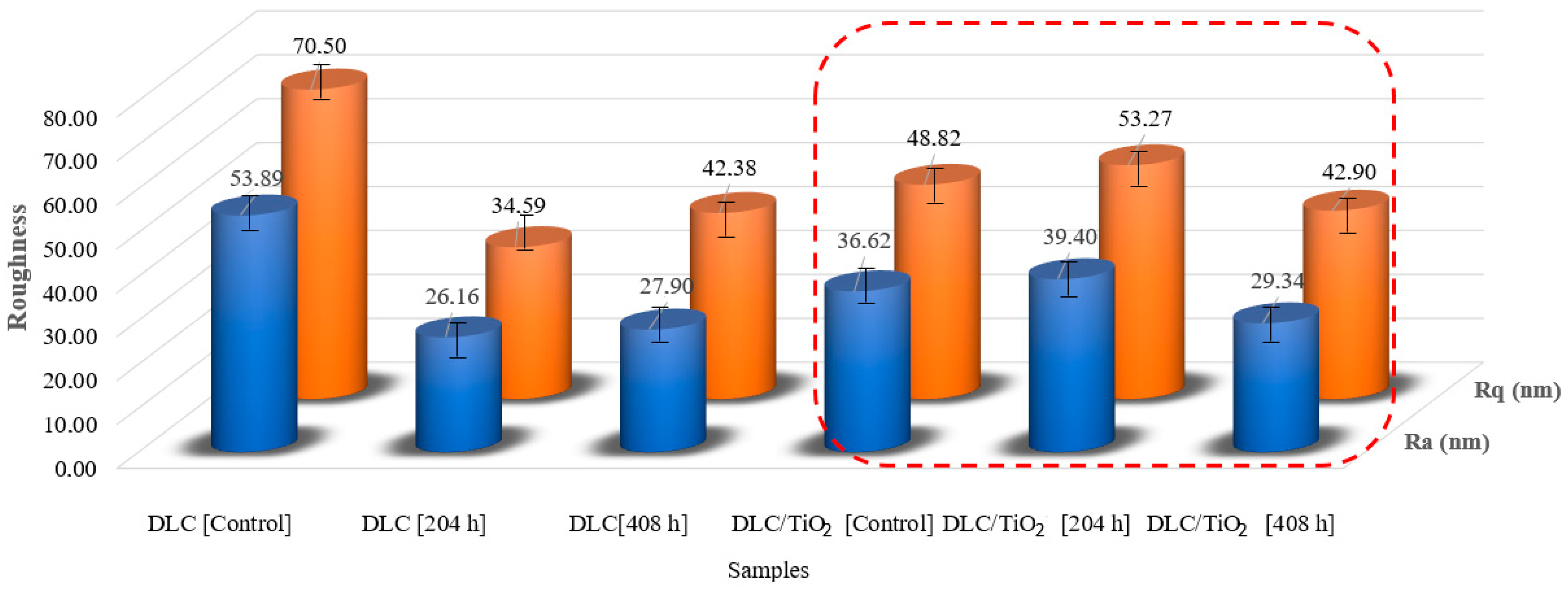
Figure 10 illustrates the Ra and Rq roughness average values measured from five distinct samples for DLC and DLC/TiO2 coatings before and after the UV aging tests. In the case of the DLC control samples, the average Ra value obtained was 53.89 nm, with an Rq value of 70.50 nm. Notably, following the UV aging tests, the roughness of the DLC samples decreased by a factor of approximately 2. The same did not occur for the DLC/TiO2-film samples. The roughness values of the control and test samples remained relatively stable, with variation close to the standard deviation.

Figure 10.
Roughness comparison among DLC and DLC/TiO2-film samples on the AISI 316L, in red frame, substrate before and after the UV aging test.
3.4. Adhesion Strength
Stress is a crucial inherent factor in DLC deposition, influencing adhesion quality [35]. Furthermore, stress is a measurable mechanical property. Similar to bulk materials, the resolution of interference-induced cracks is largely determined by mechanical properties [1].
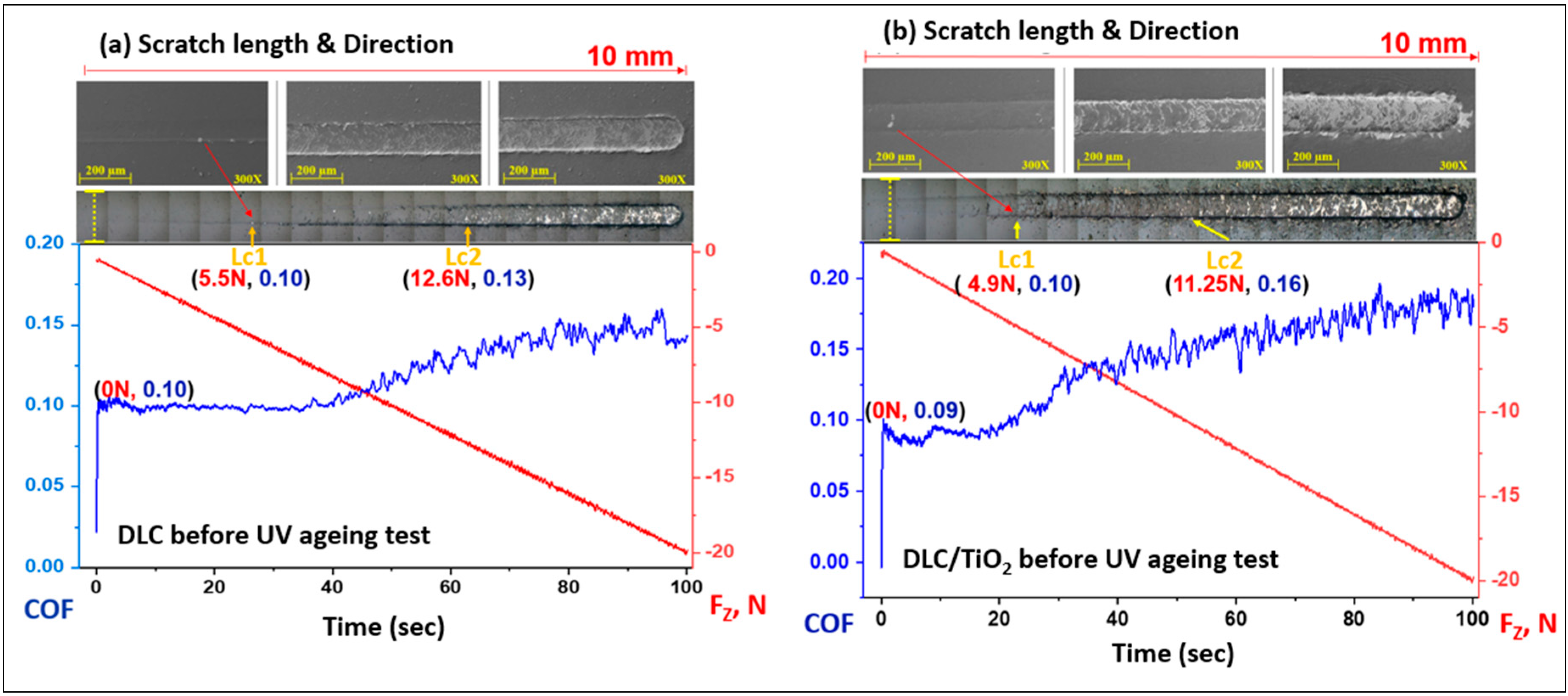
The method used for evaluating films’ cohesive and interfacial adhesive strength was the scratch test, following the procedures described in ASTM C1624-05. The adhesion strength of a coating–substrate system was assessed by optical microscopy and SEM. The images of the scratch tracks on the 316L substrate film with DLC and DLC/TiO2 were presented in Figure 11a and Figure 11b, respectively.
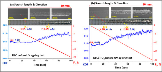
Figure 11.
SEM images of scratch test results for DLC and DLC/TiO2-film samples on AISI 316L substrate using a Rockwell C indenter before the UV aging testing. The friction coefficient (COF) is in the blue line, and the normal force is in the red line. (a) the COF rises from 0.10 to 0.14 for DLC, and (b) 0.9 to 0.18 for DLC/TiO2.
The first critical load (Lc1) is marked by the initial signs of damage or cracks in the coating, and the second critical load (Lc2) is associated with the start of chipping failure extending from the arc tensile cracks, indicating adhesive failure between the film and the substrate, with continuous substrate exposure [28,56].
The sample film with DLC exhibited the initial crack after a displacement of 2.7 mm, reaching a critical load (Lc1) of 5.5 N. The image depicts progressive failures resembling waves in that region. The adhesive failure between the film and the substrate was observed in the DLC sample after a displacement of 6.8 mm, up to a load force (Lc2) of 12.6 N. The concave curvature of the crack about the sliding direction led to cracks forming ahead of the tip during scratching, a damage mode commonly referred to as conformal cracking [28,57,58,59].
Similarly, the DLC/TiO2-film sample showed no adhesive failure with substrate exposure (Lc2) up to 11.25 N and 4.75 mm of displacement, although Lc1 occurred at 4.9 N and 2.7 mm of the beginning of scratch length. The film failures were correlated with the increase in friction forces, as indicated by a gradual rise in the friction coefficient (COF). In this case, the crack damage was characterized by a combination of buckling cracks along the scratch track due to the compressive stress field preceding the moving stylus and bucking spallation at the end of the scratch length [28].
The DLC and DLC/TiO2 films remained partially adhered to the AISI 316L substrate up to a load of 20 N, corresponding to a scratch distance of 10 mm. It still provides some lubrication between the tip and film/substrate, where the COF rises from 0.10 to 0.14 for DLC and 0.9 to 0.18 for DLC/TiO2.
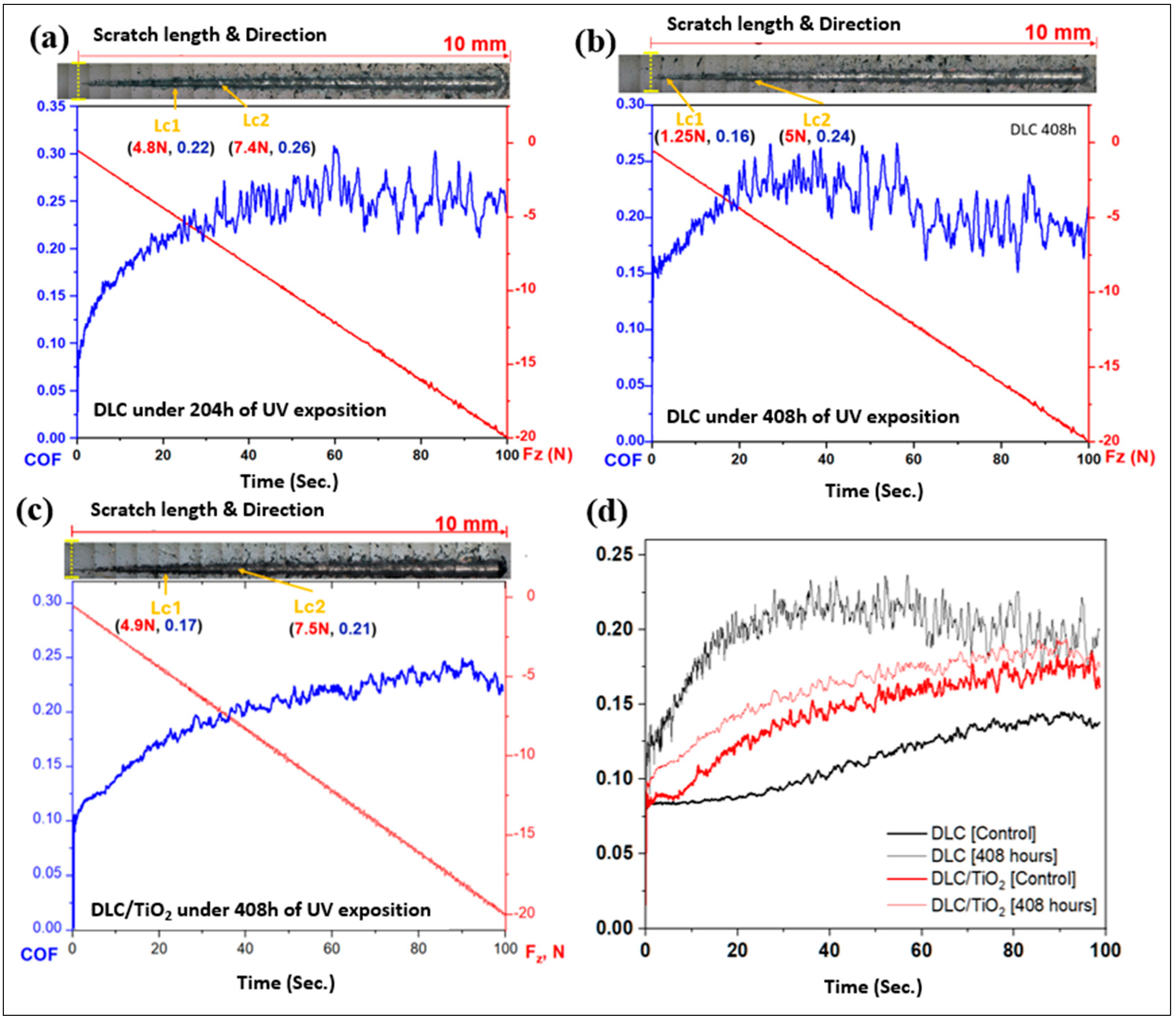
Figure 12 shows micrographs of scratch tests that were conducted on the DLC and DLC/TiO2-film samples on AISI 316L substrate using a Rockwell C indenter, in conjunction with the analysis of the friction coefficient (COF) and normal force curves and comparison of average friction coefficient (COF) curves following UV aging testing. (a) depicts the results for DLC at 204 h; (b) shows the results for DLC after 408 h; (c) shows the results for DLC/TiO2 after 408 h; (d) Comparison of average friction coefficient (COF) curves before and after UV exposure.
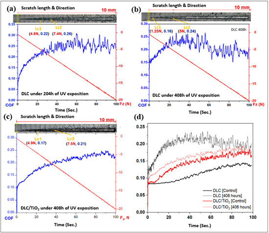
Figure 12.
Micrographs of scratch tests were conducted on the DLC and DLC/TiO2-film samples on AISI 316L substrate using a Rockwell C indenter, in conjunction with the analysis of the friction coefficient (COF) and normal force curves and comparison of average friction coefficient (COF) curves following UV aging testing. (a) depicts the results for DLC at 204 h; (b) shows the results for DLC after 408 h; (c) shows the results for DLC/TiO2 after 408 h; (d) comparison of average friction coefficient (COF) curves before and after UV exposure.
Both films had a satisfactory performance in the Scratch Test, showing good adhesion to the substrate even though DLC had better performance when compared with DLC/TiO2 film.
After 204 h of the UV aging test, the sample film with DLC exhibited the first critical load after a displacement of 2.4 mm, reaching a load force (Lc1) of 4.8 N. The adhesive failure between the film and the substrate was observed after a displacement of 3.5 mm, up to a load force (Lc2) of 7.4 N, and the COF rose from 0.08 to 0.26. As UV testing progressed, after 408 h, the first critical load occurred after a displacement of 0.4 mm, and Lc1 decreased to 1.25 N. The second critical load (Lc2) appeared after 2.2 mm of displacement with a load of 5 N, and the COF increased from 0.15 to 0.24. For DLC/TiO2-film samples, after 408 h of UV testing exposure, the first critical load occurred after a displacement of 2.0 mm, reaching a critical load (Lc1) of 4.9 N. The second critical load appeared after 3.9 mm of displacement, up to a load of 7.5 N, and the COF varied from 0.10 to 0.21. It became evident that all films experienced degradation in wear resistance and lubrication capacity.
Table 6 presents the average values of the coefficient of friction (COF) for the control samples and those coated with DLC and DLC/TiO2 after 408 h of UV exposure. When comparing the average COF for each type of sample with its respective control, an increase in the coefficient of friction is observed. However, this increase is significantly more pronounced for the sample with the DLC film, which shows a 72.72% increase in the average COF, rising from 0.11 to 0.19. In contrast, the DLC/TiO2 sample exhibits a more modest increase of 7.14%, with the average COF changing from 0.14 to 0.15.
Table 6.
Comparison of the mean value of friction coefficient [COF] among samples before and after the UV aging test.
The scratch test revealed a reduction in displacement and force necessary to initiate the failure modes, leading to a quicker depletion of their lubrication capacity; this depletion was particularly notable and more pronounced in the DLC-film specimens, confirming the protection of TiO2.
3.5. Hardness and Elastic Modulus
Nanometer-scale resolution indentation experiments were conducted on DLC and DLC/TiO2 specimens both before and after the UV aging test. This test is essential for determining the mechanical properties of DLC films, given that hardness and elastic modulus significantly influence friction and wear [33]. Therefore, a comprehensive understanding of these properties is crucial for gaining insights into tribological behavior and UV film degradation.
Hardness is quantified as the maximum load applied during indentation divided by the projected contact area, while Young’s modulus is derived from the slope of the unloading P-h curves [30,60]. To mitigate substrate influences, both hardness and Young’s modulus were assessed at an indenter penetration depth constituting less than 10% of the film’s thickness [30].
The measurements were taken at 10 different points, and the average value obtained was computed. The test results summary and the literature references are displayed in Table 7. A notable distinction in hardness is observed between the DLC and DLC/TiO2 controlled samples. Specifically, the DLC/TiO2 sample exhibits a significant reduction in hardness compared with its DLC counterpart, with the reduction in hardness being approximately 50%. This phenomenon may be attributable to the TiO2 deposition process, which requires the use of pure water as a precursor and operates under thermal conditions (at 200 °C) within the ALD reactor cycle.
Table 7.
Average hardness and elastic modulus of DLC and DLC/TiO2-film samples on AISI 316L substrate.
The deposition process, lasting approximately 1 h and 30 min, is followed by 3 h of gradual cooling, which likely contributes to the decrease in hardness. During this process, the presence of hydrogen, coupled with the elevated temperature of 200 °C, facilitates hydrogen diffusion within the film structure. Consequently, this increase in hydrogen content contributes to the diminished hardness and Young’s modulus [33].
The hardness discrepancy between DLC and DLC/TiO2 samples underscores the importance of considering deposition parameters and their effects on the resulting material characteristics.
4. Conclusions
In this study, DLC and DLC/TiO2 thin films were deposited onto a 316L stainless steel substrate using a combination of PECVD and ALD techniques. The effects of accelerated aging, induced by UV exposure, on the properties of the films were evaluated using an Accelerated Weathering Tester, following ASTM G154 practices. This assessment aimed to simulate the impact of sunlight and moisture (rain or dew) on the films under real-world conditions. The Raman spectra analysis was conducted to determine and compare film characteristics before and after 204 and 408 h of testing, including carbon phase bands, D and G band displacement, characteristic bandwidths, and the ID/IG ratio analyses.
The UV aging tests significantly impact the Raman spectrum of DLC films, leading to structural deterioration in the specimens. However, in samples with the DLC/TiO2 film, there was notable preservation of the Raman spectra signature after 204 and 408 h of testing when compared with the control sample. SEM analysis revealed no signs of cracking or delamination in the samples, although slight alterations in the color pattern were observed.
The adhesion of the films was evaluated using a scratching test following ASTM C1624 standards. Both the DLC and DLC/TiO2 films exhibited satisfactory performance both before and after the test, indicating good adhesion to the substrate. However, it is noteworthy that a progressive degradation in resistance to wear and lubrication capacity was observed in both types of films after the UV aging test. The scratch test revealed a reduction in scratch length and the force required to initiate failure modes and an increase in COF, suggesting a quicker depletion of the film. This depletion was particularly notable in DLC-film specimens.
The hardness of DLC specimens was found to decrease after the UV aging tests. Furthermore, it was noted that the TiO2 coating process significantly diminishes the hardness of the DLC film compared with DLC samples without TiO2. This reduction was more pronounced than the decrease resulting from the UV aging tests on DLC samples without the TiO2 layer. These findings emphasize the importance of thoroughly evaluating the effects of deposition processes and parameters on material characteristics.
Therefore, in applications where hardness is crucial, careful consideration should be given to utilizing this process, or alternative TiO2 deposition methods that do not compromise this property should be explored. Nonetheless, despite the hardness effect caused by the TiO2 deposition process, the TiO2 layer demonstrated its effectiveness in mitigating potential UV-induced damage in the DLC film structure.
Author Contributions
P.F.M. and L.V. conceived the work, developed the theory methodology, and performed the investigation and computations. C.H.d.S., A.A.M.V. and A.R.M. performed the analytical investigation and computations. F.d.C.M., G.J.M.F. and L.V. established the analytical methods. L.V. provided supervision and final revision. All authors have read and agreed to the published version of the manuscript.
Funding
This study was financed in part by the Coordenação de Aperfeiçoamento de Pessoal de Nível Superior-Brazil (CAPES)—Finance Code 001.
Institutional Review Board Statement
Not applicable.
Informed Consent Statement
Not applicable.
Data Availability Statement
The authors declare data will be available upon request.
Conflicts of Interest
The authors declare no conflicts of interest.
References
- Rajak, D.K.; Kumar, A.; Behera, A.; Menezes, P.L. Diamond-Like Carbon (DLC) Coatings: Classification, Properties, and Applications. Appl. Sci. 2021, 11, 4445. [Google Scholar] [CrossRef]
- Liu, X.; Wang, L.; Pu, J.; Xue, Q. Surface composition variation and high-vacuum performance of DLC/ILs solid-liquid lubricating coatings: Influence of space irradiation. Appl. Surf. Sci. 2012, 258, 8289–8297. [Google Scholar] [CrossRef]
- Wu, Y.; Li, H.; Ji, L.; Liu, L.; Ye, Y.; Chen, J.; Zhou, H. Effect of vacuum annealing on the microstructure and tribological behaviour of hydrogenated amorphous carbon films prepared by magnetron sputtering. Proc. Inst. Mech. Eng. Part J J. Eng. Tribol. 2013, 227, 729–737. [Google Scholar] [CrossRef]
- Rao, J.; Lawson, K.J.; Nicholls, J.R. The characterisation of e-beam evaporated and magnetron sputtered carbon films fabricated for atomic oxygen sensors. Surf. Coat. Technol. 2005, 197, 154–160. [Google Scholar] [CrossRef]
- Adliene, D.; Laurikaitiene, J.; Tamulevičius, S. Modification of amorphous DLC films induced by MeV photon irradiation. Nucl. Instrum. Methods Phys. Res. Sect. B Beam Interact. Mater. At. 2008, 266, 2788–2792. [Google Scholar] [CrossRef]
- Vankar, V.D.; Dilawar, N. Ion irradiation effects in diamond and diamond-like carbon thin films. Vacuum 1996, 47, 1275–1280. [Google Scholar] [CrossRef]
- Shan, C.X.; Hou, X.; Choy, K.L. Corrosion resistance of TiO2 films grown on stainless steel by atomic layer deposition. Surf. Coat. Technol. 2008, 202, 2399–2402. [Google Scholar] [CrossRef]
- Mohr, L.C.; Capelezzo, A.P.; Baretta, C.R.D.M.; Martins, M.A.P.M.; Fiori, M.A.; Mello, J.M.M. Titanium dioxide nanoparticles applied as ultraviolet radiation blocker in the polylactic acid biodegradable polymer. Polym. Test. 2019, 77, 105867. [Google Scholar] [CrossRef]
- Hanaor, D.A.H.; Sorrell, C.C. Review of the anatase to rutile phase transformation. J. Mater. Sci. 2011, 46, 855–874. [Google Scholar] [CrossRef]
- Weng, K.W.; Huang, Y.P. Preparation of TiO2 thin films on glass surfaces with self-cleaning characteristics for solar concentrators. Surf. Coat. Technol. 2013, 231, 201–204. [Google Scholar] [CrossRef]
- Matějová, L.; Cieslarová, M.; Matěj, Z.; Daniš, S.; Peikertová, P.; Šihor, M.; Lang, J.; Matějka, V. Microstructure, optical and photocatalytic properties of TiO2 thin films prepared by chelating-agent assisted sol-gel method. J. Nanosci. Nanotechnol. 2016, 16, 504–514. [Google Scholar] [CrossRef]
- Colmenares, J.C.; Luque, R.; Campelo, J.M.; Colmenares, F.; Karpiński, Z.; Romero, A.A. Nanostructured photocatalysts and their applications in the photocatalytic transformation of lignocellulosic biomass: An overview. Materials 2009, 2, 2228–2258. [Google Scholar] [CrossRef]
- Zia, A.W.; Birkett, M. Deposition of diamond-like carbon coatings: Conventional to non-conventional approaches for emerging markets. Ceram. Int. 2021, 47, 28075–28085. [Google Scholar] [CrossRef]
- Schlebrowski, T.; Acharchi, H.; Hahn, B.; Wehner, S.; Fischer, C.B. Refinement of sustainable polybutylene adipate terephthalate (PBAT) with amorphous hydrogenated carbon films (a-C:H) Revealing Film Instabilities Influenced by a thickness-dependent change of sp2/sp3 ratio. Materials 2020, 13, 1077. [Google Scholar] [CrossRef]
- Vitelaru, C.; Parau, A.C.; Constantin, L.R.; Kiss, A.E.; Vladescu, A.; Sobetkii, A.; Kubart, T. A strategy for alleviating micro arcing during HiPIMS deposition of DLC coatings. Materials 2020, 13, 1038. [Google Scholar] [CrossRef] [PubMed]
- Malisz, K.; Świeczko-Żurek, B.; Sionkowska, A. Preparation and Characterization of Diamond-like Carbon Coatings for Biomedical Applications—A Review. Materials 2023, 16, 3420. [Google Scholar] [CrossRef]
- Capote, A.; Capote, G.; Corat, E.J.; Trava-Airoldi, V.J. Effect of low-pressure deposition on the mechanical and tribological properties of a-C:H films deposited via modified pulsed-DC PECVD with active screen as an additional cathode. Surf. Coat. Technol. 2022, 445, 128716. [Google Scholar] [CrossRef]
- Zheng, J.; Liu, Q.; Li, Z. Effect of negative bias voltage on properties of hydrogenated diamond-like carbon films. Guangxue Jingmi Gongcheng/Opt. Precis. Eng. 2022, 30, 411–420. [Google Scholar] [CrossRef]
- Liu, Z.; Yin, P.; Wei, X.; Ding, Q.; Cao, X.; Zhang, G.; Xue, Q. Simultaneous deposition of DLC film on the internal surface of multiple pipes. Diam. Relat. Mater. 2022, 127, 109187. [Google Scholar] [CrossRef]
- Bora, J.; Basumatary, B.; Podder, S.; Gogoi, D.; Sharma, B.; Bhagowati, P.; Choudhury, B.; Patil, D.S.; Pal, A.R. A substrate constituent Na-catalyzed growth of carbon nanotubes on glass substrate by atmospheric pressure PECVD. Appl. Surf. Sci. 2024, 648, 158988. [Google Scholar] [CrossRef]
- Guo, C.Q.; Li, H.Q.; Peng, Y.L.; Dai, M.J.; Lin, S.S.; Shi, Q.; Wei, C.B. Residual stress and tribological behavior of hydrogen-free Al-DLC films prepared by HiPIMS under different bias voltages. Surf. Coat. Technol. 2022, 445, 128713. [Google Scholar] [CrossRef]
- Liaqat, M.A.; Hussain, Z.; Khan, Z.; Akram, M.A.; Shuja, A. Effects of Ag doping on compact TiO2 thin films synthesized via one-step sol–gel route and deposited by spin coating technique. J. Mater. Sci. Mater. Electron. 2020, 31, 7172–7181. [Google Scholar] [CrossRef]
- Yang, B. Applications of Titania Atomic Layer Deposition in the Biomedical Field and Recent Updates. Am. J. Biomed. Sci. Res. 2020, 8, 465–468. [Google Scholar] [CrossRef]
- Wu, Y.; Yang, X.; Chen, H.; Zhang, K.; Qin, C.; Liu, J.; Peng, W.; Islam, A.; Bi, E.; Ye, F.; et al. Highly compact TiO2 layer for efficient hole-blocking in perovskite solar cells. Appl. Phys. Express 2014, 7, 052301. [Google Scholar] [CrossRef]
- Aghaee, M.; Verheyen, J.; Stevens, A.A.E.; Kessels, W.M.M.; Creatore, M. TiO2 thin film patterns prepared by chemical vapor deposition and atomic layer deposition using an atmospheric pressure microplasma printer. Plasma Process. Polym. 2019, 16, 1900127. [Google Scholar] [CrossRef]
- Bonetti, L.F.; Capote, G.; Santos, L.V.; Corat, E.J.; Trava-Airoldi, V.J. Adhesion studies of diamond-like carbon films deposited on Ti6Al4V substrate with a silicon interlayer. Thin Solid Film. 2006, 515, 375–379. [Google Scholar] [CrossRef]
- Macário, P.F.; Vieira, A.; Manfroi, L.; da Silva, M.G.P.; Leite, P.; Vieira, L. Corrosion behavior of Al2024-T3, Al5052-H32, and Al6061-T6 aluminum alloys coated with DLC films in aviation fuel medium, Jet A-1 and AVGAS 100LL. Mater. Corros. 2019, 70, 2278–2291. [Google Scholar] [CrossRef]
- ASTM C1624-05; Standard Test Method for Adhesion Strength and Mechanical Failure Modes of Ceramic Coatings by Quantitative Single Point Scratch Testing. ASTM-International: West Conshohocken, PA, USA, 2005; pp. 1–28.
- Oliver, W.C.; Pharr, G.M. An improved technique for determining hardness and elastic modulus using load and displacement sensing indentation experiments. J. Mater. Res. 1992, 7, 1564–1583. [Google Scholar] [CrossRef]
- Fang, T.H.; Chang, W.J. Nanomechanical characterization of amorphous hydrogenated carbon thin films. Appl. Surf. Sci. 2006, 252, 6243–6248. [Google Scholar] [CrossRef]
- ASTM-G154; Standard Practice for Operating Fluorescent Light Apparatus for UV Exposure of Nonmetallic Materials. ASTM-International: West Conshohocken, PA, USA, 2000.
- Ouyang, Y.; Cong, L.M.; Chen, L.; Liu, Q.X.; Fang, Y. Raman study on single-walled carbon nanotubes and multi-walled carbon nanotubes with different laser excitation energies. Phys. E Low-Dimens. Syst. Nanostruct. 2008, 40, 2386–2389. [Google Scholar] [CrossRef]
- Fontaine, J.; Donnet, C.; Erdemir, A. Fundamentals of the tribology of DLC coatings. In Tribology of Diamond-Like Carbon Films; Springer: Boston, MA, USA, 2008; pp. 139–154. [Google Scholar]
- Pierson, H.O. Handbook of Carbon, Graphite, Diamonds and Fullerenes; Noyes Publications: Norwich, NY, USA, 1993; pp. 43–69. [Google Scholar]
- Robertson, J. Diamond-like amorphous carbon. Mater. Sci. Eng. R Rep. 2002, 37, 129–281. [Google Scholar] [CrossRef]
- Ferrari, A.C.; Robertson, J. Resonant Raman spectroscopy of disordered, amorphous, and diamondlike carbon. Phys. Rev. B 2001, 64, 075414. [Google Scholar] [CrossRef]
- Ferrari, A.C.; Robertson, J. Raman spectroscopy of amorphous, nanostructured, diamond-like carbon, and nanodiamond. Philos. Trans. A Math. Phys. Eng. Sci. 2004, 362, 2477–2512. [Google Scholar] [CrossRef]
- Grill, A. Diamond-like carbon: State of the art. Diam. Relat. Mater. 1999, 8, 428–434. [Google Scholar] [CrossRef]
- Guo, D.; Zhang, S.; Huang, T.; Wu, S.; Ma, X.; Guo, F. Corrosion Properties of DLC Film in Weak Acid and Alkali Solutions. Coatings 2022, 12, 1776. [Google Scholar] [CrossRef]
- Zavaleyev, V.; Walkowicz, J.; Sawczak, M.; Moszyński, D.; Ryl, J. Effect of substrate bias on the properties of DLC films created using a combined vacuum arc. Bull. Mater. Sci. 2021, 44, 170. [Google Scholar] [CrossRef]
- Zhang, C.Z.; Tang, Y.; Li, Y.S.; Yang, Q. Adhesion enhancement of diamond-like carbon thin films on Ti alloys by incorporation of nanodiamond particles. Thin Solid Film. 2013, 528, 111–115. [Google Scholar] [CrossRef]
- Fayed, S.M.; Chen, D.; Li, S.; Zhou, Y.; Wang, H.; Sadawy, M.M. Corrosion behavior and passive stability of multilayer DLC-Si coatings. Surf. Coat. Technol. 2022, 431, 128001. [Google Scholar] [CrossRef]
- Schwan, J.; Ulrich, S.; Batori, V.; Ehrhardt, H.; Silva, S.R.P. Raman spectroscopy on amorphous carbon films. J. Appl. Phys. 1996, 80, 440–447. [Google Scholar] [CrossRef]
- Ferrari, A.C.; Robertson, J. Interpretation of Raman spectra of disordrred and amorphous carbon. Surf. Coat. Technol. 2000, 61, 14095. [Google Scholar]
- Marciano, F.R.; Bonetti, L.F.; Pessoa, R.S.; Massi, M.; Santos, L.V.; Trava-Airoldi, V.J. Oxygen plasma etching of silver-incorporated diamond-like carbon films. Thin Solid Film. 2009, 517, 5739–5742. [Google Scholar] [CrossRef]
- Capote, G.; Silva, G.F.; Trava-Airoldi, V.J. Effect of hexane precursor diluted with argon on the adherent diamond-like properties of carbon films on steel surfaces. Thin Solid Film. 2015, 589, 286–291. [Google Scholar] [CrossRef]
- Rodriguez, B.J.; Navabpour, P.; Proprentner, D.; Walker, M.; Sun, H.; Schiller, T.L. An alternative approach to the tribological analysis of Si-doped DLC coatings deposited with different bias voltages using Raman spectroscopy mapping. Emergent Mater. 2021, 4, 1595–1604. [Google Scholar] [CrossRef]
- Rao, X.; Yang, J.; Chen, Z.; Yuan, Y.; Chen, Q.; Feng, X.; Qin, L.; Zhang, Y. Tuning C–C sp2/sp3 ratio of DLC films in FCVA system for biomedical application. Bioact. Mater. 2020, 5, 192–200. [Google Scholar] [CrossRef] [PubMed]
- Aobo Wei Guozheng Ma, G.L.Z.L.C.H.H.Z.W.G.Z.X.; Haidou, W. Effect of space UV irradiation on the mechanical and tribological properties of Cr and B doped hydrogen-containing diamond-like films. Fuller. Nanotub. Carbon Nanostruct. 2023, 31, 513–522. [Google Scholar]
- Staszuk, M. Application of PVD and ALD methods for surface treatment of Al-Si-Cu alloys. Solid State Phenom. 2019, 293, 97–109. [Google Scholar] [CrossRef]
- Chiappim, W.; Testoni, G.E.; de Lima, J.S.B.; Medeiros, H.S.; Pessoa, R.S.; Grigorov, K.G.; Vieira, L.; Maciel, H.S. Effect of Process Temperature and Reaction Cycle Number on Atomic Layer Deposition of TiO2 Thin Films Using TiCl4 and H2O Precursors: Correlation Between Material Properties and Process Environment. Braz. J. Phys. 2016, 46, 56–69. [Google Scholar] [CrossRef]
- Aarik, L.; Arroval, T.; Rammula, R.; Mändar, H.; Sammelselg, V.; Aarik, J. Atomic layer deposition of TiO2 from TiCl4 and O3. Thin Solid Film. 2013, 542, 100–107. [Google Scholar] [CrossRef]
- Wadullah, H.M.; Ajeel, S.A.; Abbass, M.K. Synthesis and Characterization of Nanocoatings Thin films by Atomic Layer Deposition for Medical Applications. IOP Conf. Ser. Mater. Sci. Eng. 2019, 518, 032057. [Google Scholar] [CrossRef]
- Abas, M.; Al Awadh, M.; Habib, T.; Noor, S. Analyzing Surface Roughness Variations in Material Extrusion Additive Manufacturing of Nylon Carbon Fiber Composites. Polymers 2023, 15, 3633. [Google Scholar] [CrossRef]
- Kadhim, H.K.; Alyounis, M. Effect of surface roughness on the interface behavior of clayey soils. Open Eng. 2024, 14, 20220578. [Google Scholar] [CrossRef]
- Sveen, S.; Andersson, J.M.; M’Saoubi, R.; Olsson, M. Scratch adhesion characteristics of PVD TiAlN deposited on high speed steel, cemented carbide and PCBN substrates. Wear 2013, 308, 133–141. [Google Scholar] [CrossRef]
- Ligot, J.; Benayoun, S.; Hantzpergue, J.J. Analysis of cracking induced by scratching of tungsten coatings on polyimide substrate. Wear 2000, 243, 85–91. [Google Scholar] [CrossRef]
- Burnett, P.J.; Rickerby, D.S. The relationship between hardness and scratch adhession. Thin Solid Film. 1987, 154, 403–416. [Google Scholar] [CrossRef]
- Bull, S.J. Failure mode maps in the thin film scratch adhesion test. Tribol. Int. 1997, 30, 491–498. [Google Scholar] [CrossRef]
- Savvides, N.; Bell, T.J. Microhardness and Young’s modulus of diamond and diamondlike carbon films. J. Appl. Phys. 1992, 72, 2791–2796. [Google Scholar] [CrossRef]
- Bec, S.; Tonck, A.; Fontaine, J. Nanoindentation and nanofriction on DLC films. Philos. Mag. 2006, 86, 5465–5476. [Google Scholar] [CrossRef]
- Bewilogua, K.; Hofmann, D. History of diamond-like carbon films—From first experiments to worldwide applications. Surf. Coat. Technol. 2014, 242, 214–225. [Google Scholar] [CrossRef]


Disclaimer/Publisher’s Note: The statements, opinions and data contained in all publications are solely those of the individual author(s) and contributor(s) and not of MDPI and/or the editor(s). MDPI and/or the editor(s) disclaim responsibility for any injury to people or property resulting from any ideas, methods, instructions or products referred to in the content. |
© 2024 by the authors. Licensee MDPI, Basel, Switzerland. This article is an open access article distributed under the terms and conditions of the Creative Commons Attribution (CC BY) license (https://creativecommons.org/licenses/by/4.0/).