Article

The Influence of Bias Voltage on the Structure and Properties of TiZrNbMo Coating Deposited by Magnetron Sputtering

by
Svitlana Romaniuk
1,*,
Katarzyna Nowakowska-Langier
1,
Grzegorz Witold Strzelecki
1,
Katarzyna Mulewska
1,2 and
Roman Minikayev
3
1
Material Physics Department, National Centre for Nuclear Research (NCBJ), Andrzeja Sołtana 7, 05-400 Otwock, Poland
2
NOMATEN Centre of Excellence, National Centre for Nuclear Research (NCBJ), Andrzeja Sołtana 7, 05-400 Otwock, Poland
3
Institute of Physics, Polish Academy of Sciences, Lotników Av. 32/46, 02-668 Warsaw, Poland
*
Author to whom correspondence should be addressed.
Coatings 2024, 14(7), 844; https://doi.org/10.3390/coatings14070844
Submission received: 31 May 2024 / Revised: 1 July 2024 / Accepted: 3 July 2024 / Published: 5 July 2024
(This article belongs to the Special Issue Advanced Nanostructured Coatings Deposited by Magnetron Sputtering)

Abstract

:
TiZrNbMo coatings have been deposited using the direct current pulsed magnetron sputtering method in an argon atmosphere. The synthesis processes have been conducted under various process parameters. The structure (chemical and phase composition) and mechanical properties of the obtained multicomponent coatings are investigated as a function of plasma modulation frequency (10 Hz and 1000 Hz) and substrate bias (0 to −150 V). It is the case that an increase in the substrate bias decreases the deposition rate and alters the coating’s chemical composition. The latter leads to a Ti concentration decrease and a simultaneous increase in Mo and Nb concentrations in the final coating material. X-ray diffraction measurements indicate a single-phase BCC structure, with grain size decreasing as substrate bias increases. This ultimately forms an amorphous–nanocrystalline structure at −150 V. The mechanical properties of the multicomponent TiZrNbMo coatings have been determined using the nanoindentation method. The maximum values of hardness (13.45 GPa) and elastic modulus (188.6 GPa) are achieved at a substrate bias of −150 V. We also show that the minimum elastic modulus (41.8 GPa) is achieved at an intermediate substrate bias of −100 V.

1. Introduction

The ever-increasing requirements for the quality and properties of medical devices create a demand for new effective materials. Medical metal implants must be characterized by good biocompatibility and excellent mechanical properties: high fatigue strength and hardness, corrosion resistance, good ductility, low modulus of elasticity, and excellent wear resistance. They must be made of non-toxic and hypoallergenic components [1,2,3,4] to withstand harsh working and environmental conditions, which has always been a problem in customarily used medical metal materials. One of the promising areas in the development and production of new materials is the creation of multi-component coatings with a unique combination of properties that are fundamentally different from those obtained by conventional methods. Both the coating composition and technology of obtaining protective coatings are being constantly improved. Currently, medium-entropy alloys (MEA) and high-entropy alloys (HEA) are actively being developed and investigated [5,6,7]. They represent a type of multicomponent alloy and are considered promising materials for industrial applications. The contents and ratio of each component are taken into account in the case of multicomponent alloys. By reducing or increasing the proportion of additional elements, one may generate a variety of metallographic structures which have a significant effect on the properties of alloys [8,9,10]. The selection of the composition of the multicomponent composition was determined primarily by the operating conditions. One of the titanium-based compositions for medical devices is the TiZrNbMo alloy. However, the main obstacle to the wider use of HEAs containing expensive elements is the cost of manufacturing entire products from them. To reduce the cost of such items while ensuring superior surface properties, it is possible to apply an HEA coating with the required composition. Depending on the ratio of components in the MoNbTiZr alloy and the method of production, its structure and phase composition can significantly vary. In the as-cast state, the TiZrNbMo 0.6 alloy exhibits two (BCC) lattice structures, labeled as BCC1 and BCC2, with lattice parameters of 0.332 nm and 0.338 nm, respectively [11]. According to the authors, such phase separation is caused by the significant difference in atomic radii and melting temperatures. Increasing the concentration of titanium to more than 50 atomic percent results in the formation of a cast TiZrNbMo alloy with a BCC lattice [12]. The TiMoNbZr coatings, synthesized using laser cladding, consist of a primary body-centered cubic (BCC) matrix phase and several hexagonally close-packed (HCP) phases [13,14]. The MoxNbTiZr coatings exhibit a dendritic microstructure with Mo-rich dendritic regions, rich in Nb, and interdendritic regions rich in Zr [13]. Equiatomic ZrNbTiMo coatings, synthesized by direct current magnetron sputtering (power of 150 W), exhibit a single body-centered cubic lattice structure [15]. However, as the substrate bias increases (from 0 to −200 V), the preferred grain orientation changes from (110) to (200). Additionally, the mechanical properties of the ZrNbTiMo HEA coating significantly change depending on the synthesis parameters.
The aim of this study is to obtain multicomponent coatings with high contents of Ti, Nb, Zr, and Mo elements using the pulsed magnetron sputtering (PMS) method from the mosaic target. Additionally, the study seeks to investigate the extent to which varying synthesis process parameters can control the structure, chemical composition, and phase composition of the coatings, thereby directly influencing their properties.

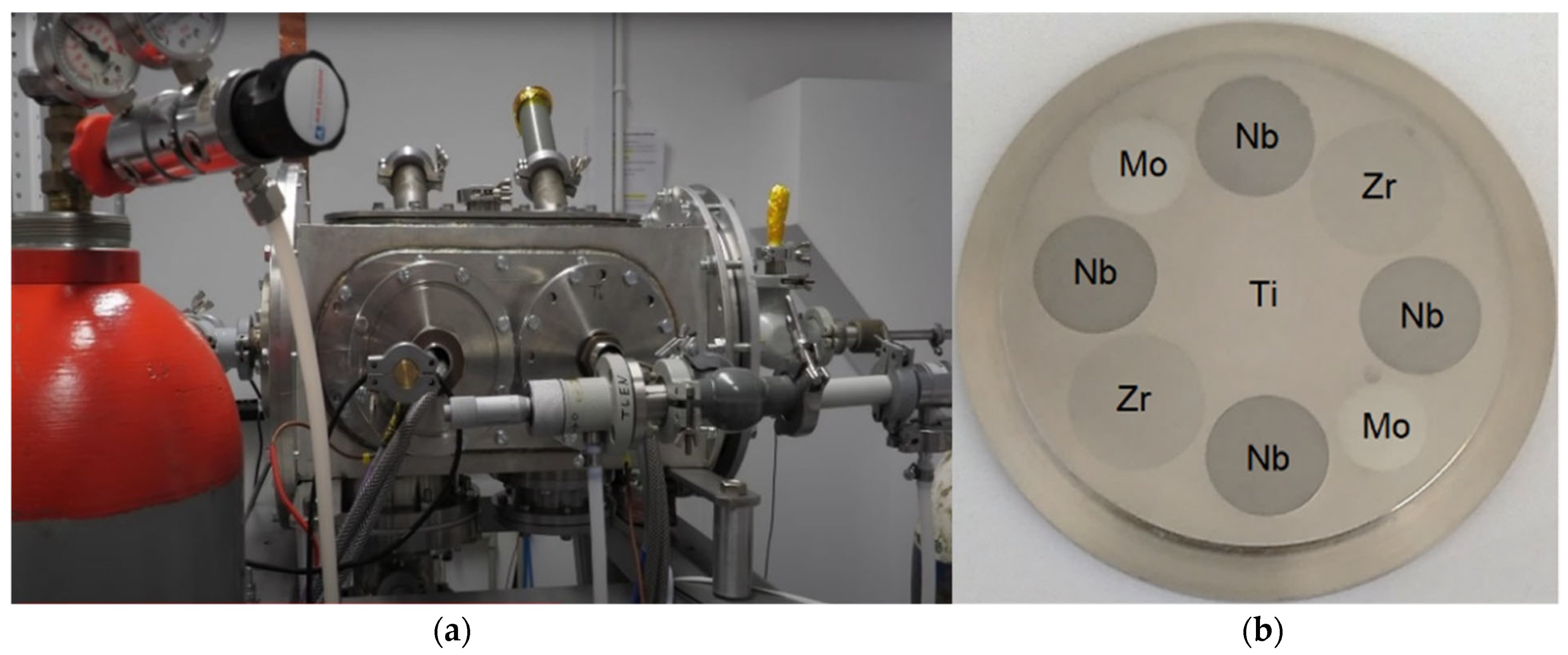
2. Materials and Methods

The WMK 50 (IMT, Wroclaw University of Technology, Poland) unbalanced magnetron was used in the synthesis by the Pulsed Magnetron Sputtering (PMS) method (Figure 1a) [16]. The magnetron was powered by a 10 kW pulse power supply DORA PS, operating in DC mode with a main frequency of 100 kHz and modulation frequencies of 1000 Hz and 10 Hz. During the coating deposition, a constant power of 1000 W was applied to the target. The substrate bias ranged from 0 to −150 V. The processes were carried out in an argon atmosphere under a dynamic pressure of pAr = 0.5 Pa. Coatings were synthesized on non-heated silicon substrates (Lukasiewicz Research Network—Institute of Electronic Materials Technology, Warsaw, Poland). All the samples had dimensions of 20 × 20 [mm]. The Si substrate used has a (100) orientation with a max disorientation of 15°. The substrates were ultrasonically cleaned using a Codyson 0.6L 50W CD3800 device (Shenzhen Codyson Electrical Co., Shenzhen, China) in acetone (Linegal Chemicals, Warsaw, Poland) and then mounted on a stage positioned 100 mm away from the magnetron cathode. All technological parameters of the coating deposition for each test sample are given in Table 1.
A 50 mm diameter and a 6 mm thick mosaic target was used as a magnetron cathode. The selection of the composition of the multicomponent composition was determined by the required level of performance properties. The mosaic target (Figure 1b) consisted of a titanium base (40.13 at. %) with metal inserts made of zirconium 18.48 at. %, niobium 31.5 at %, and molybdenum 9.89 at. % (Grade 1 purity). The calculation of the estimated share of individual metallic components of the target was performed in the same way as in our previous work [16].
The microstructure, cross-sectional morphology, and chemical composition of the coatings were determined by scanning electron microscopy (SEM, on Zeiss EVO® MA10, Jena, Germany) combined with X-ray dispersive energy spectrometry (Bruker’s EDS Detector, SEM, Zeiss, Jena, Germany). The structure and phase compositions of the coatings were investigated by X-ray diffraction (XRD) using monochromatized Cu-K radiation on an X’Pert MPD (XRD, Malvern-Panalitical, Almelo, Netherlands) laboratory diffractometer.
The interplanar spacing (d) of films was calculated according to the Bragg equation:
2dsinθ = λ
The lattice constant (a) of the films was theoretically estimated using the rule-of-mixtures approach (2) [17] and calculated based on experimental data using Equation (3):
amix = ∑ ciai
where ci is the atomic fraction and ai is the lattice parameter o element i.
d = a h 2 + k 2 + l 2
where h, k, and l are indices of crystallographic planes.
To assess the ability to form a solid solution and predict phase formation in TiZrNbMo coatings, the thermodynamic parameters proposed by the authors of [1,18] were used: the valence electron concentration (VEC), the atomic radius difference criterion (δ), the enthalpy (ΔHmix), and entropy of mixing ΔSmix.
The mechanical properties of the coatings were measured by using the NanoTest Vanatge System (MicroMaterials Ltd., Wrexham, UK), using the Berkovich diamond triangular pyramid. Fifteen probes were applied on the sample and the results were averaged. The indentations were carried out in the single mode with a load of 1 mN. The indentation depth did not exceed 85 nm. As a result of nanoindentation, data regarding the nanohardness (H) and reduced Young’s modulus (Er), the resistance to plastic deformation H3/Er2, as well as the indicators determining the wear resistance of coatings (H/Er and We) were obtained. The nanohardness and reduced Young’s modulus (Er) were calculated from the nanoindentation load–displacement curves using the Oliver and Pharr model. The elastic recovery value We was calculated from the loading–unloading curves and determined by the following formula:
W e = h max h r h max × 100 %
where hmax is the maximum penetration depth, and hr is the residual depth after a load relief.

3. Results and Discussion

Using scanning electron microscopy (SEM with EDX), a comparative analysis of the composition of the coatings was conducted. The EDX spectrum (Figure 2) consisted of characteristic peaks of titanium, zirconium, niobium, and molybdenum without the presence of any other impurity peaks. It was found that the proposed cathode composition (see Figure 1b) and synthesis parameters (see Table 1) ensure an almost uniform distribution of components in the TiZrNbMo coating. The data scatter in several analyzed micron-sized areas on the surface of each coating did not exceed ± 0.5 at. %.
A significant difference in the chemical composition of the obtained coatings compared to the concentrations of Zr, Nb, Ti, and Mo in the cathode was identified. The variation in the content of elements is primarily associated with their sputtering efficiency (Figure 3) and the different predisposed conditions during the synthesis process.
Bias voltage, power, and the frequency of the magnetron discharge regulate the energy of ions and electrons impacting the films during their growth. This affects the structure of the coatings, their crystalline orientation, porosity, adhesion, and thickness. Bias voltage can affect the chemical composition of coatings. Different elements in a target may sputter at different rates, and bias voltage can exacerbate this effect, leading to variations in composition. For instance, elements with lower sputtering yields might become deficient in their coating, while those with higher sputtering yields might become excessive. This phenomenon depends on preferential sputtering. Therefore, in the case of multicomponent alloy coatings, bias voltage can influence the relative amounts of the constituent elements. The content of Ti and Zr slightly increases in the substrate bias range from 0 to −50 V, as these lighter components receive more kinetic energy. Consequently, there is an observed increase in the thickness of the coating of 22% (Figure 4). Higher bias voltages can cause differential sputtering rates due to differences in atomic mass and binding energies, potentially leading to non-uniform or altered alloy compositions. The higher ion energies resulting from higher bias voltages can promote the formation of metastable phases due to increased kinetic energy and altered surface diffusion dynamics. With an increase in substrate bias from −50 V to −150 V, the concentration of elements with lighter atomic masses decreases. The atomic mass of titanium is the lowest, making it more susceptible to the re-sputtering effect under high bias voltage, resulting in a decrease in its content. Simultaneously, the concentration of Nb and Mo increases (Figure 5). The higher concentration of niobium compared to titanium may be attributed to the higher sputtering yield of niobium and its atomic weight being twice that of titanium. The observed effect is intensified with an increase in modulation frequency. The concentration of titanium decreases by a factor of 3 at a modulation frequency of 1000 Hz and by 1.6 times at 10 Hz, which is due to its repeated sputtering at a higher substrate bias.
As shown in Figure 5, frequency modulation does not significantly affect changes in the chemical composition but contributes to synthesis conditions conducive to the formation or disruption of the columnar structure as well as the thickness of coatings (Figure 6a,b). As is well known, both the composition and the formed structure influence the physical and mechanical properties. Therefore, conducting phase state analysis and understanding the conditions necessary for its creation are also essential.
The data presented in Table 2 suggest the formation of a stable and chemically inert TiZrNbMo coating with a low enthalpy of formation.
An additional parameter analyzed during the investigation of coatings is the bond order (Bo). This parameter serves as a measure of the strength of covalent bonds between titanium and alloying elements [19]. Alloying a titanium alloy with the components Zr, Nb, and Mo, which have a high value of bond order Bo, will also contribute to the increased phase stability of the obtained compositions (Table 3).
During the formation of coatings with a complex composition containing Zr, Nb, Ti, and Mo, various structures can be formed depending on their ratios. It is important to understand the phase formation processes and assess the possibilities of forming various solid solutions and intermetallic compounds. Based on the theoretical assessment of the phase-forming ability of the Ti-Zr-Nb-Mo composition (Figure 7), it follows that in most cases, such a composition will be a high-entropy alloy when the concentration of all components is above 15 at.% (ΔSmix ≥ 11 J/mol K [1,20]).
There are several approaches and criteria for predicting the phase stability of HEAs. For most of the obtained ZrNbTiMo coatings (Table 4), the theoretical conditions for forming a high-entropy solid solution are met, and the thermodynamic parameters are within the specified limits: 11 J/K·mol ≤ ΔSmix ≤ 19.5 J/K·mol, −22 kJ/mol ≤ ΔHmix ≤ 7 kJ/mol, and 0 ≤ δ ≤ 8.5% [21]. However, for samples No.3 and 4, the parameter ΔSmix is below the specified limit. With a lower value of ΔSmix (ΔSmix ≥ 7), but simultaneously with a more negative ΔHmix and higher δ, amorphous phases may form. Additionally, any alloy can become amorphous if a sufficiently high cooling rate is provided [21]. The authors of [22] proposed the following criteria as necessary conditions for the formation of stable solid solution phases: δ ≤ 6.6% and Ω ≥ 1.1. These criteria are met for all the obtained coatings. The concentration of valence electrons (VEC), calculated using expression (6), is a decisive parameter for predicting the formed solid solution phase. From the analysis of data in the literature and theoretical calculations (see Table 4) for the chosen composition, it follows that, for all the obtained coatings, the condition VEC ≤ 6.87 is met. This suggests that the obtained coatings tend to form an FCC structure. However, it should be noted that the formed structure and phase stability also depend on the synthesis parameters and the temperature during the coating deposition process.
There is a qualitative relationship between the mechanical and chemical characteristics of a substance as well as the width and shape of diffraction lines. Therefore, X-ray diffraction (Figure 8) was used to investigate the phase composition of the coatings. The most intense peak at 2θ = 69.19° corresponds to the Si peak (400) from the substrate, and also the peak at 2θ = 32.98° is a trace from the forbidden peak (200). The low-intensity peak at 2θ ~ 55° is detector noise. If the clear diffraction maxima at the positions around 37.1 and 79.2 degrees of 2θ in samples No.1–3 are attributed to the planes (110) and (220) adjacent to the BCC-structure, respectively, the lattice parameters found from the positions of 220 peaks (corrected to the position of the Si (400) peak based on the monocrystalline silicon lattice parameter [23]) will range from 3.360(2) to 3.419(2) Å. The possibility of the growth of such or similar structures is shown in Refs. [15,24]. In addition, the peaks are asymmetric, indicating a scatter of interplane distances and therefore some heterogeneity and defects distribution in the material composition. It should be noted that in such coatings, the formation of the most densely packed plane (110) in the BCC structure, from the thermodynamic point of view, will contribute to high levels of deformations (stresses). Increasing the residual compressive stresses would enhance the hardness. The obtained experimental results are in agreement with the estimation of the theoretical unit cell size and indicate the formation of TiZrNbMo coatings with nanocrystalline BCC structure. However, the experimental a values are slightly higher than the theoretical ones (Table 5) obtained based on the chemical composition. In both cases, there is a similar trend of increasing the lattice constant with increasing the substrate bias voltage. The observed differences are attributed to the fact that theoretical calculations do not account for real lattice defects, such as Frenkel pairs and anti-Schottky defects. As the bias voltage increases, the number of point defects increases, leading to the expansion of the unit cell and an increase in the lattice constant. Consequently, a deformation field is created, hindering the movement of dislocations and increasing the hardness of the coatings [25]. The interplanar spacing in the crystal lattice of TiZrNbMo coatings increases depending on the synthesis parameters. The changes in the width and shift of the diffraction peaks towards smaller angles observed in Figure 8 are due to the detected changes in the composition of the coatings. An increase in peak width (with increasing applied bias voltage) suggests changes in the microstructural characteristics of the coating. The coating formed in the absence of bias voltage is presumed to have the largest grain size, in our case approximately up to 20–25 nm (based on the Debye–Scherrer equation). This coating is characterized by the highest concentration of titanium. Point defects resulting from ion bombardment serve as nucleation centers, promoting the crystallization of new grains. Due to rapid cooling, the nucleation process prevails over grain growth, leading to the formation of finer grains at higher substrate bias voltages. Additionally, variations in the concentration of Nb in the coating composition are believed to influence the microstructure, contributing to a fine-grained structure. These combined factors are hypothesized to reduce the grain size to around a few nanometers. A finer grain structure with more grain boundaries can inhibit dislocation sliding. Sample No.4 is characterized by a broad diffraction peak. Adjusting the synthesis parameters of these coatings, particularly the substrate bias voltage up to −150 V, promotes the formation of an amorphous–nanocrystalline structure (Figure 6c), attributed to high-energy ion bombardment. Similar structural changes, namely, grain size reduction and an increase in the content of the amorphous phase when applying negative bias voltages, have also been observed by other researchers [26,27,28,29] in nitride compositions.
From the analysis of data from the literature, it can be inferred that titanium alloys with a β-phase mostly exhibit the lowest modulus [30]. Moreover, the Young’s modulus decreases with an increasing Bo value. Alloying a titanium alloy with components possessing high Bo values, specifically Zr, Nb, and Mo, will not only promote phase stability but also lead to the attainment of β-phase alloys with a low Young’s modulus. According to theoretical data, the modulus of elasticity for an alloy composition consisting of Ti, Zr, Nb, and Mo can vary from 101 GPa (for an alloy with the minimum amount of molybdenum—5% Ti25Zr35Nb35Mo5) to 177 GPa for the Ti35Zr5Nb25Mo35 alloy (Figure 9a). For the obtained coatings, the minimum value is 132.51 GPa for sample No.3. As a result of the conducted experimental research, it has been established that under the given synthesis parameters, the modulus of elasticity of the obtained coatings varies widely from 41.8 to 188.6 GPa. The minimum value of the modulus of elasticity is 41.8 GPa for sample No.3 (at −100 V). In this sample, there is an increased concentration of zirconium, which has the maximum atomic radius and the minimum value of the modulus of elasticity. The modulus of elasticity values for samples No.2 and 3 are significantly lower than those of SS 316L steel (197 GPa), Co–Cr–Mo (199 GPa), and Ti–6Al–4V (110 GPa). Increasing the bias voltage on the substrate contributes to the formation of coatings with smaller grain sizes, denser structures, and higher residual compressive stresses [15,31,32,33], leading to an increase in hardness (Figure 9b), reaching a maximum value of 13.45 GPa at −150 V. The difference in hardness values for the obtained coatings reaches 62.6%. The observed variation in mechanical properties is attributed to both the conditions of coating deposition and significant differences in microstructure and phase composition. Increasing the concentration of components with smaller radii by 42.8% Mo (with the maximum value of the modulus of elasticity) and 48.5% Nb may additionally lead to lattice deformation and influence the hardness level. This, in combination with the deposition conditions, promotes the formation of a coating with maximum hardness and modulus of elasticity. According to data in the literature, the observed high elasticity in sample No.4 may also be attributed to the combination of high strength and low stiffness characteristic of metallic glasses [18]. Such alloys can accumulate elastic deformation energy and release it. The mechanical properties of samples No.5–8, obtained at a modulation frequency of 10 Hz, were not investigated because their thickness (see Figure 4) did not meet the requirements for nanoindentation testing.
The hardness level, to varying degrees, increases in most coatings synthesized by magnetron sputtering using bias voltage on the substrate. Meanwhile, the modulus of elasticity changes inconsistently. For some coatings, a decrease in this parameter is observed [26], while for others, a maximum is observed at −100 V followed by slight decrease [34]. Coatings such as (AlCrNbSiTiMo)N and (AlCrMoSiTi)N [31,32] exhibit similar changes to the investigated TiZrNbMo coatings. The hardness level increases, while the modulus of elasticity reaches its minimum value at an intermediate bias voltage of −100 V. Moreover, for equiatomic crystalline TiZrNbMo coatings synthesized by magnetron sputtering at lower power with the application of bias voltage on the substrate, there is a characteristic increase in both hardness and modulus of elasticity [15]. The identified difference is explained by the influence of all synthesis parameters (considering the component ratios) on the properties of the coatings. This confirms the necessity of detailed studies on the structure and properties of the composition under different deposition parameters.
To predict the wear resistance of the coatings based on nanoindentation results, the elastic strain to failure (H/Er) [35], the plastic deformation coefficient (H3/Er2) [36], and the elastic recovery (We, %) were also evaluated (Table 6).
The value of H/Er for the TiZrNbMo coating varies from 0.07 to 0.21, H3/Er2 ranges from 0.05 to 0.39, and the value of We reaches 78.34%. The maximum values of H/Er, H3/Er2, and We correspond to the TiZrNbMo coating deposited at a substrate bias voltage of −100 V. Good wear resistance is achieved at high values of H/Er and H3/Er2. Resistance to plastic deformation is ensured by increasing the hardness level of the coating. For the distribution of applied load over a wider area within the coating, a low value of the effective modulus of elasticity is desirable [25]. The obtained results of good wear resistance of the coating make them promising as a protective coating. The final selection of deposition parameters and coating composition depends on the required operational properties of the working surface. For medical purposes, it is efficient to use sample No.3, as one of the primary requirements for implant properties is a low modulus of elasticity. This will enhance the interaction between bone tissue and the surface of the implants.

4. Conclusions

After the deposition of multi-component TiZrNbMo coatings using pulse magnetron sputtering in argon plasma under various plasma generation conditions, the following results were obtained:
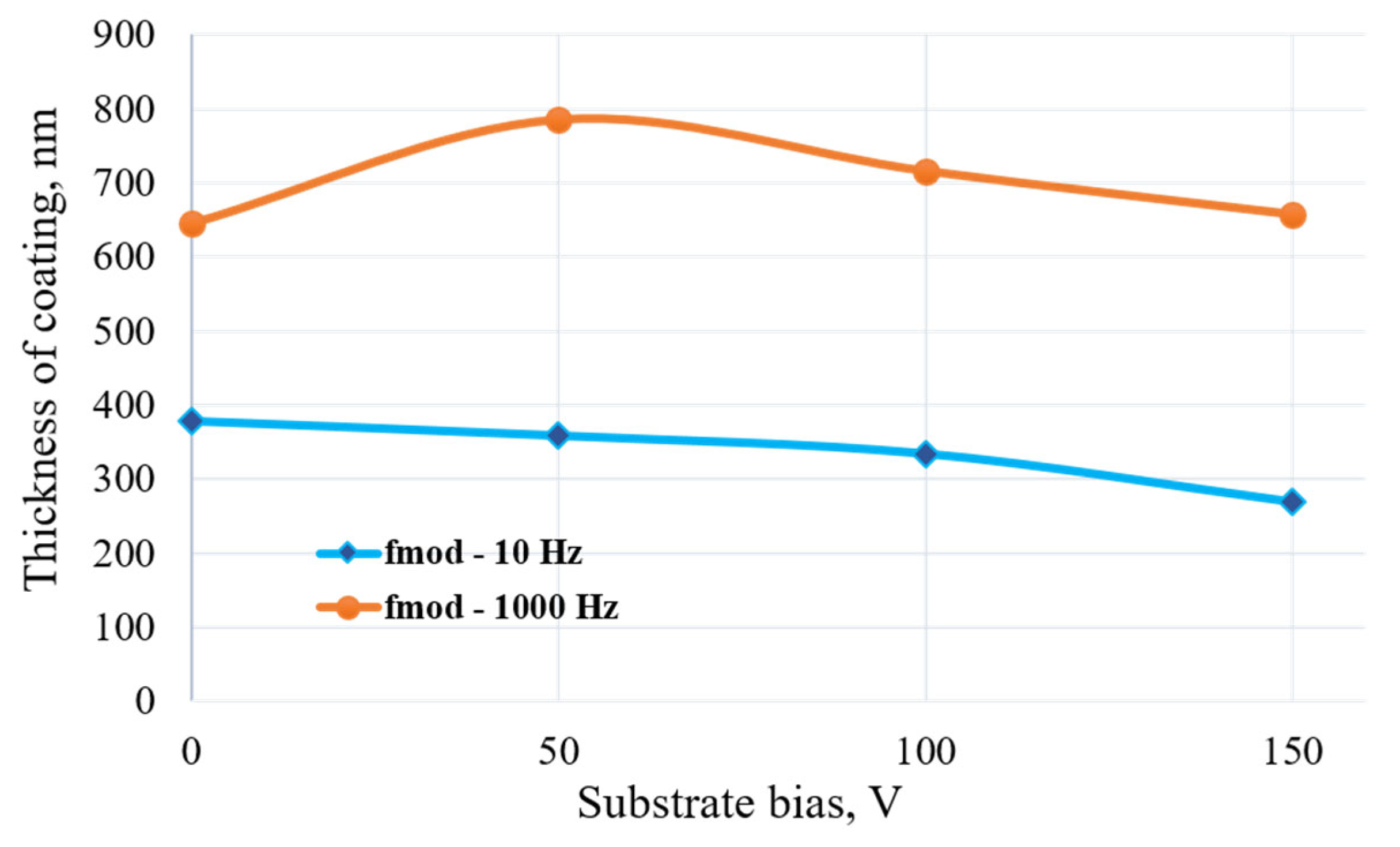
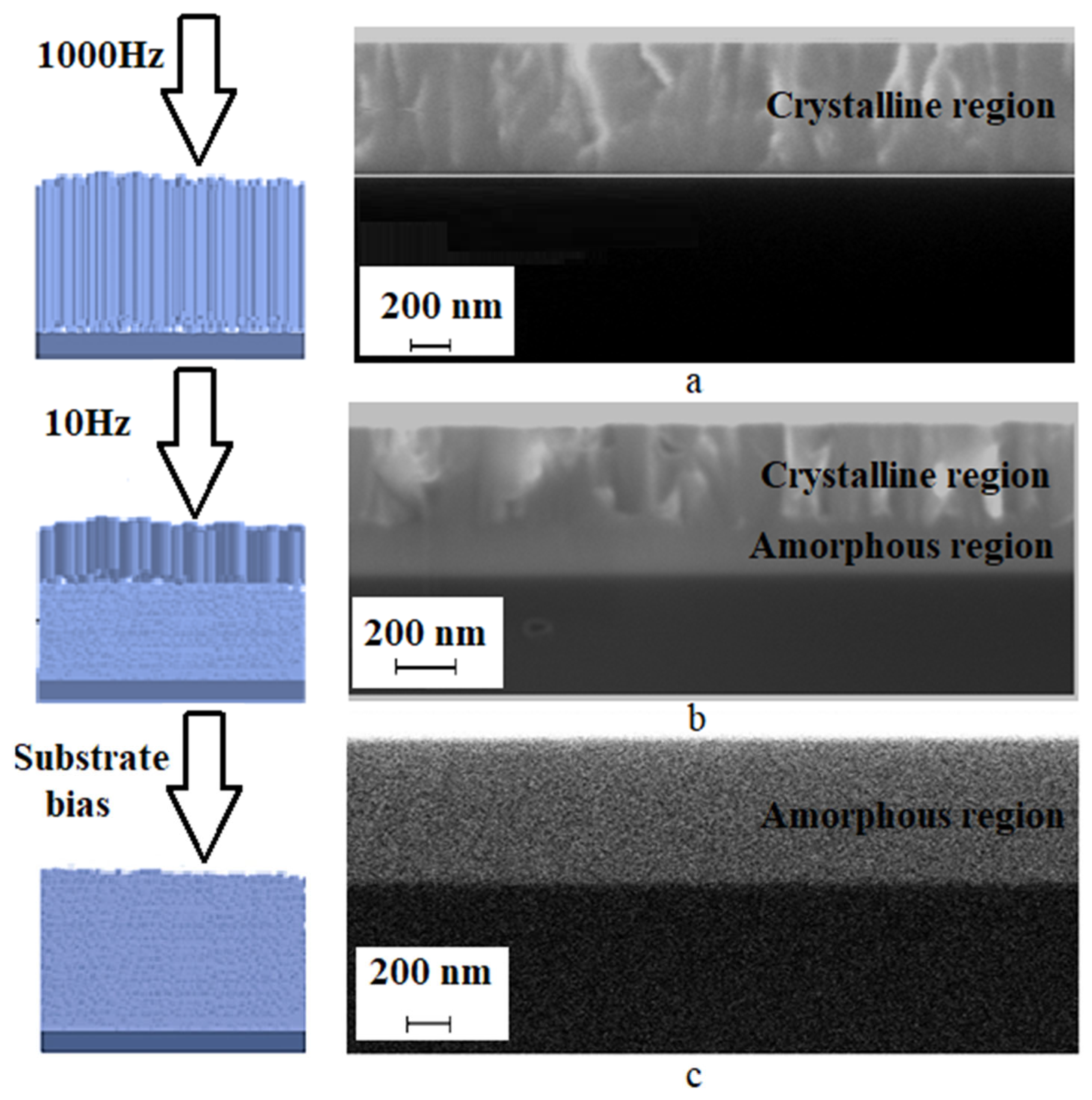
  • Increasing the modulation frequency (from 10 Hz to 1000 Hz) promotes the formation of a columnar structure and increases the coating thickness.
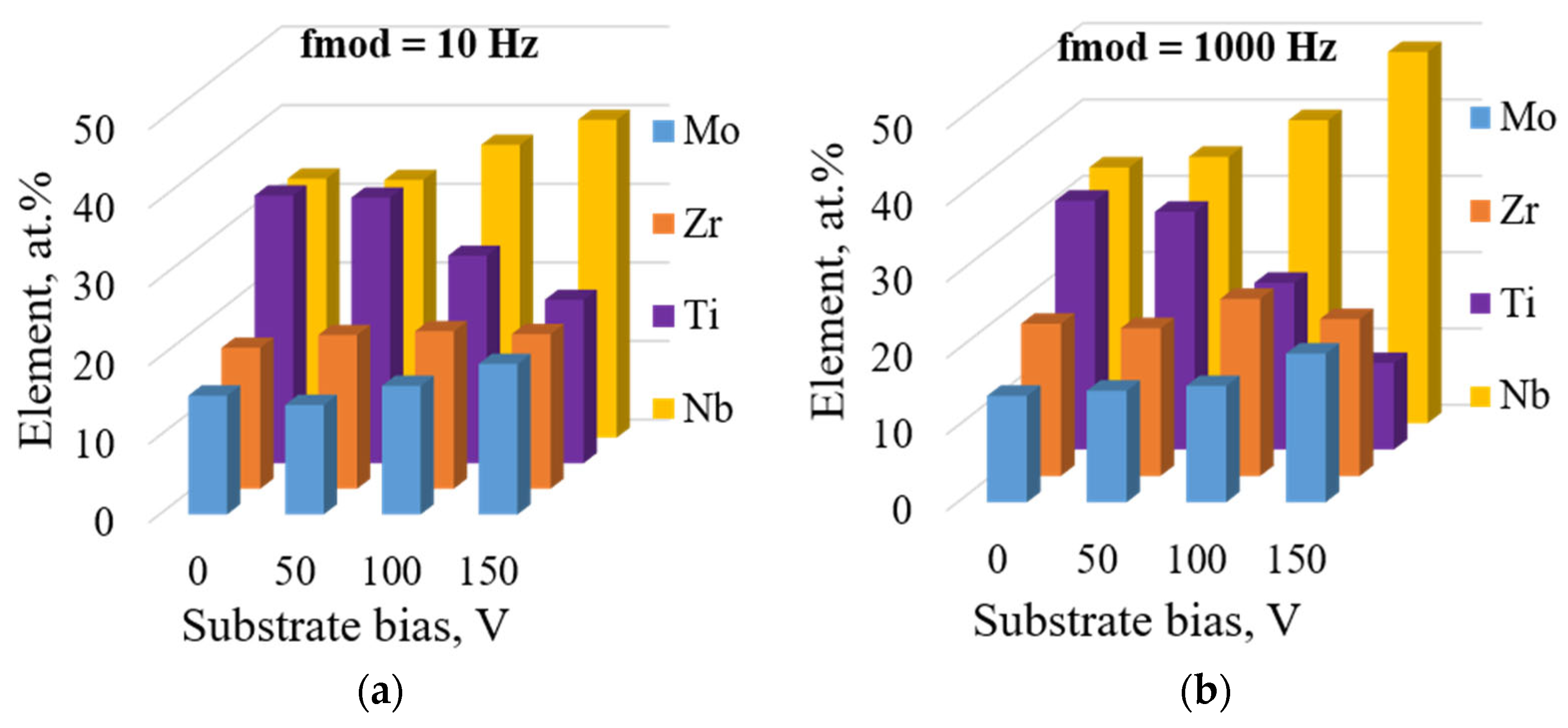
  • Increasing the negative voltage on the substrate decreases the deposition rate and significantly changes the chemical composition of the coating. The concentration of titanium decreases by a factor of three, while the concentrations of Mo and Nb increase by 42.8% and 48.5%, respectively.
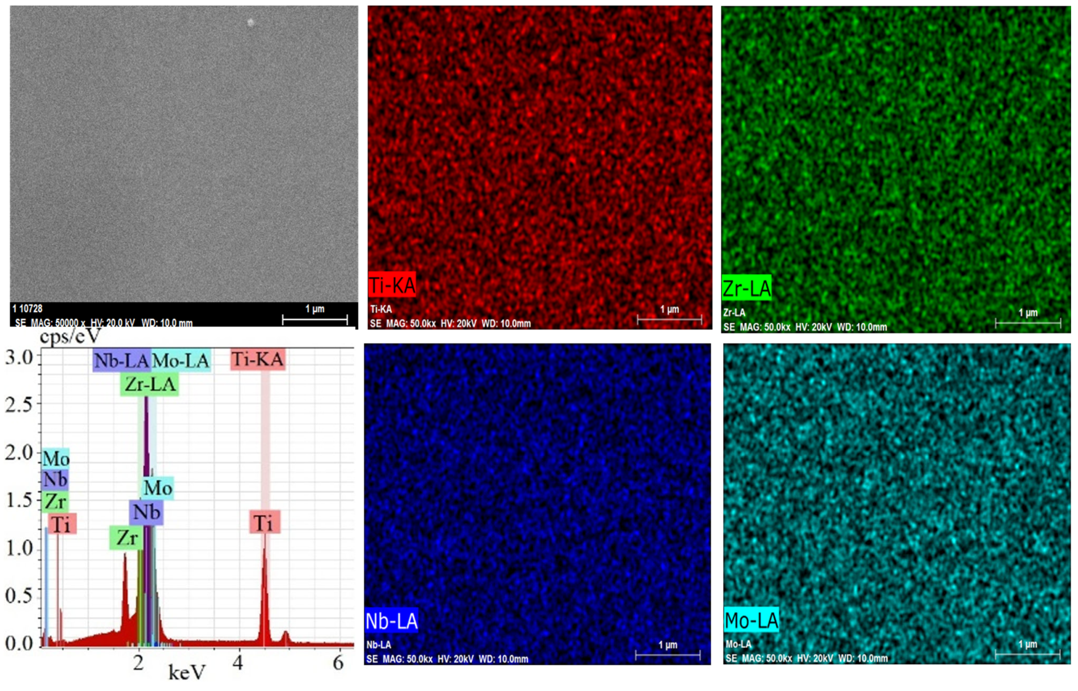
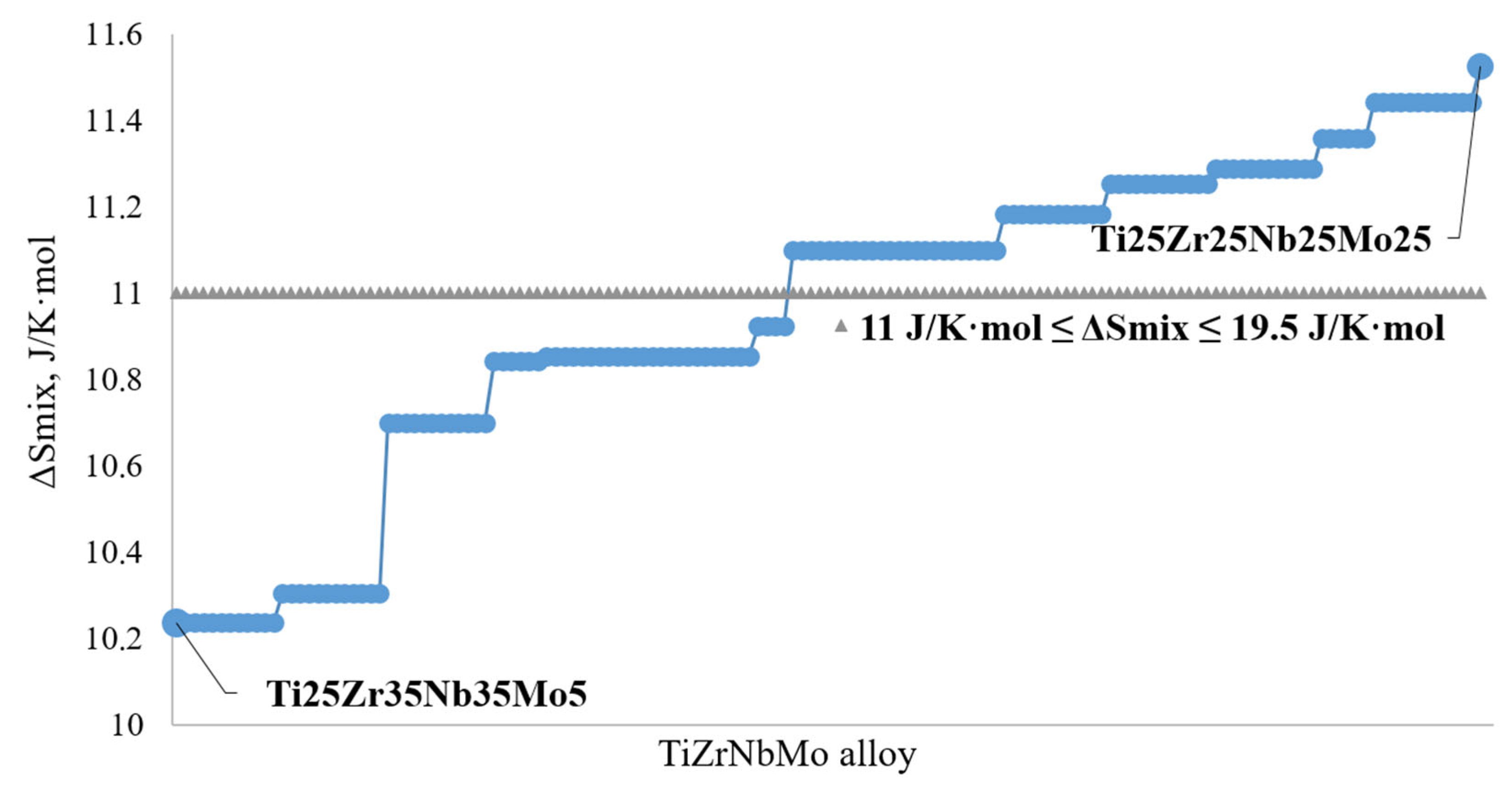
  • Experimental data confirmed the theoretical assessments. The deposited TiZrNbMo coatings exhibited a homogeneous body-centered cubic (BCC) structure of solid solution without the presence of intermetallic compounds.
  • The preferred crystallographic orientation for all coatings was (110). With an increase in the negative voltage on the substrate, the intensity and width of the diffraction peak decreases, as does the grain size. Coatings with the smallest grain size were obtained with a substrate bias of −100 V. At higher substrate biases (−150 V), an amorphous–nanocrystalline structure is formed.
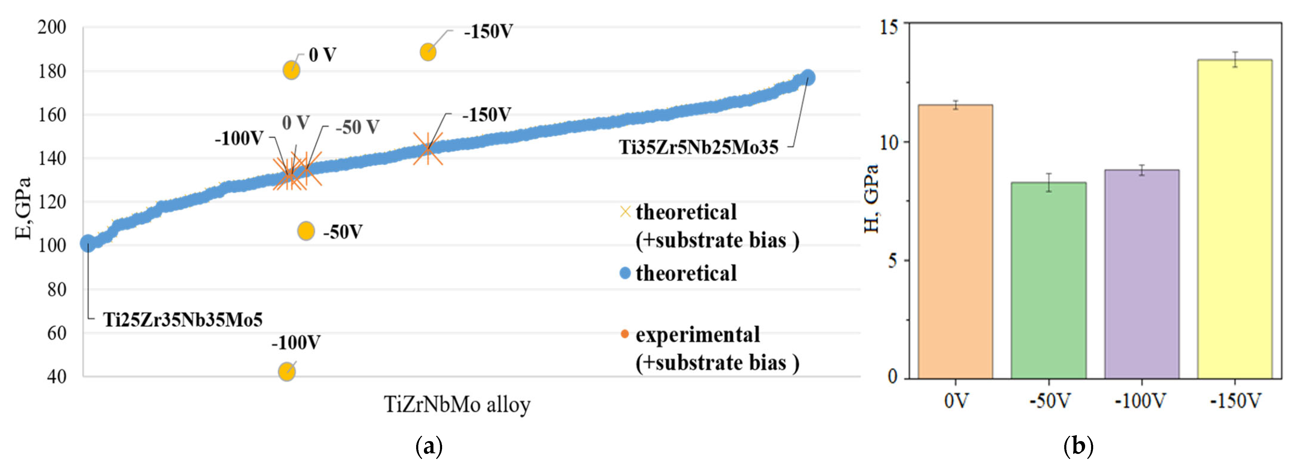
  • With an increase in the substrate bias voltage, the hardness of the coating increases. The maximum values of hardness (13.45 GPa) and elastic modulus (188.6 GPa) are achieved at a substrate bias voltage of −150 V. Meanwhile, the minimum value of the elastic modulus (41.8 GPa) is attained at an intermediate substrate bias voltage of −100 V.
  • The good correlation between the theoretical data and experimental results indicates the feasibility of using the magnetron sputtering method to obtain coatings with desired properties.

Author Contributions

Conceptualization, S.R. and K.N.-L.; methodology, S.R. and K.N.-L.; validation, S.R. and K.N.-L.; formal analysis, S.R., K.M., R.M. and K.N.-L.; investigation, S.R., G.W.S., K.M. and R.M.; resources, K.N.-L.; data curation, S.R.; writing—original draft preparation, S.R. and K.N.-L.; writing—review and editing, S.R. and K.N.-L.; supervision, S.R. and K.N.-L. All authors have read and agreed to the published version of the manuscript.

Funding

This research received no external funding.

Institutional Review Board Statement

Not applicable.

Informed Consent Statement

Not applicable.

Data Availability Statement

Data are contained within the article.

Conflicts of Interest

The authors declare no conflicts of interest.

References

  1. Geanta, V.; Voiculescu, I.; Vizureanu, P.; Sandu, A.V. High Entropy Alloys for Medical Applications. Eng. Steels High Entropy-Alloys 2019, 10, 181–198. [Google Scholar] [CrossRef]
  2. Taran, V.S.; Garkusha, I.E.; Taran, A.V.; Muratov, R.M.; Vorontsov, P.M.; Gnidenko, Y.P.; Herasimov, H.M.; Starikov, V.V.; Baturin, A.A.; Romaniuk, S.P. Functional protective ZrN coatings on implants for trauma surgery. Probl. At. Sci. Technol. 2020, 130, 115–118. [Google Scholar] [CrossRef]
  3. Geantă, V.; Voiculescu, I.; Ştefănoiu, R.; Codescu, M.; Kelemen, H.; Pavel, G.; Vlădescu, A.; Sandu, V.A. Obtaining and characterisation of high entropy alloys used for medical applications. IOP Conf. Ser. Mater. Sci. Eng. 2019, 572, 012023. [Google Scholar] [CrossRef]
  4. Taran, V.; Garkusha, I.; Tymoshenko, O.; Taran, A.; Misiruk, I.; Skoblo, T.; Romaniuk, S.; Starikov, V.; Baturin, A.; Nikolaychuk, G. Development of niobium based coatings prepared by ion-plasma vacuum-arc deposition. Plasma Med. 2020, 10, 61–69. [Google Scholar] [CrossRef]
  5. Todai, M.; Nagase, T.; Hori, T.; Matsugaki, A.; Sekita, A.; Nakano, T. Novel TiNbTaZrMo high-entropy alloys for metallic biomaterials. Scr. Mater. 2017, 129, 65–68. [Google Scholar] [CrossRef]
  6. Popescu, G.; Ghiban, B.; Popescu, C.A.; Rosu, L.; Truscă, R.; Carcea, I.; Soare, V.; Dumitrescu, D.; Constantin, I.; Olaru, M.T. New TiZrNbTaFe high entropy alloy used for medical. IOP Conf. Ser. Mater. Sci. Eng. 2018, 400, 022049. [Google Scholar] [CrossRef]
  7. Wang, S.-P.; Xu, J. TiZrNbTaMo high-entropy alloy designed for orthopedic implants: As-cast microstructure and mechanical properties. Mater. Sci. Eng. C 2017, 73, 80–89. [Google Scholar] [CrossRef] [PubMed]
  8. Martins, D.Q.; Osório, W.R.; Souza, E.P.; Caram, R.; Garcia, A. Effects of Zr content on microstructure and corrosion resistance of Ti–30Nb–Zr casting alloys for biomedical applications. Electrochim. Acta 2008, 53, 2809–2817. [Google Scholar] [CrossRef]
  9. Dai, S.; Wang, Y.; Chen, F.; Yu, X.; Zhang, Y. Influence of Zr content on microstructure and mechanical properties of implant Ti–35Nb–4Sn–6Mo–xZr alloys. Trans. Nonferr. Met. Soc. China 2013, 23, 1299–1303. [Google Scholar] [CrossRef]
  10. Nnamchi, P.S. First principles studies on structural, elastic and electronic properties of new Ti-Mo-Nb-Zr alloys for biomedical applications. Mater. Des. 2016, 108, 60–67. [Google Scholar] [CrossRef]
  11. Jin, C.; Li, X.; Li, H.; Li, Q.; Wang, H. Tribological performance of a TiZrNbMo0.6 refractory high entropy alloy at elevated temperatures. J. Alloys Compd. 2022, 920, 165915. [Google Scholar] [CrossRef]
  12. Wong, K.; Hsu, H.; Wu, S.; Ho, W. Structure and properties of Ti-rich Ti–Zr–Nb–Mo medium-entropy alloys. J. Alloys Compd. 2021, 868, 159137. [Google Scholar] [CrossRef]
  13. Liu, H.; Wang, R.; Gao, Q.; Chen, P.; Hao, J.; Yang, H.; Liu, X. Evolution in microstructure and tribological behavior of laser cladded MoxNbTiZr high-entropy refractory alloy coatings with varying Mo content. Mater. Charact. 2023, 206, 113449. [Google Scholar] [CrossRef]
  14. Liu, L.; Liu, H.; Zhang, X.; Wang, Y.; Hao, X. Corrosion Behavior of TiMoNbX (X = Ta, Cr, Zr) Refractory High Entropy Alloy Coating Prepared by Laser Cladding Based on TC4 Titanium Alloy. Materials 2023, 16, 3860. [Google Scholar] [CrossRef] [PubMed]
  15. Wang, J.; Liu, X.; Zhang, Y.; Cai, W.; Wang, L.; Tang, L. Effect of substrate bias on the microstructure and mechanical and tribological properties of ZrNbTiMo refractory high entropy alloy film. Surf. Coat. Technol. 2023, 455, 129214. [Google Scholar] [CrossRef]
  16. Strzelecki, G.W.; Nowakowska-Langier, K.; Mulewska, K.; Zieliński, M.; Kosińska, A.; Okrasa, S.; Wilczopolska, M.; Chodun, R.; Wicher, B.; Mirowski, R.; et al. Multi-component low and high entropy metallic coatings synthesized by pulsed magnetron sputtering. Surf. Coat. Technol. 2022, 446, 128802. [Google Scholar] [CrossRef]
  17. Senkov, O.N.; Wilks, G.B.; Miracle, D.B.; Chuang, C.P.; Liaw, P.K. Refractory high-entropy alloys. Intermetallics 2010, 18, 1758–1765. [Google Scholar] [CrossRef]
  18. Zhang, Y.; Zhou, Y.J.; Lin, J.P.; Chen, G.L.; Liaw, P.K. Solid-solution phase formation rules for multi-component alloys. Adv. Eng. Mater. 2008, 10, 534–538. [Google Scholar] [CrossRef]
  19. Morinaga, M. The Molecular Orbital Approach to Titanium Alloy Design. Key Eng. Mater. 2018, 770, 217–223. [Google Scholar] [CrossRef]
  20. Changxi, L.; Chengliang, Y.; Jia, L.; Yujin, T.; Zhengjie, L.; Long, L.; Hai, L.; Weijie, L.; Liqiang, W. Medical high-entropy alloy: Outstanding mechanical properties and superb biological compatibility. Front. Bioeng. Biotechnol. 2020, 10, 952536. [Google Scholar]
  21. Guo, S.; Liu, C.T. Phase stability in high entropy alloys: Formation of solid-solution phase or amorphous phase. Prog. Nat. Sci. Mater. Int. 2011, 21, 433–446. [Google Scholar] [CrossRef]
  22. Yang, X.; Zhang, Y. Prediction of high-entropy stabilized solid-solution in multi-component alloys. Mater. Chem. Phys. 2012, 132, 233–238. [Google Scholar] [CrossRef]
  23. Mohr, P.J.; Taylor, B.N.; Newell, D.B. CODATA recommended values of the fundamental physical constants: 2006. Rev. Mod. Phys. 2008, 80, 633. [Google Scholar] [CrossRef]
  24. Liu, X.; Cai, W.; Zhang, Y.; Wang, L.; Wang, J. Tuning microstructure and mechanical and wear resistance of ZrNbTiMo refractory high-entropy alloy films via sputtering power. Front. Mater. 2023, 10, 1145631. [Google Scholar] [CrossRef]
  25. Peng, H.-E.; Lee, C.-Y.; Chang, H.-Y.; Yeh, J.-W. Effect of Substrate Bias on the Microstructure and Properties of Non-Equimolar (AlCrSiTiZr)N Films with Different Cr/Zr Ratios Deposited Using Reactive Direct Current Magnetron Sputtering. Coatings 2023, 13, 1985. [Google Scholar] [CrossRef]
  26. Cao, F.; Munroe, P.; Zhou, Z.; Xie, Z. Influence of substrate bias on microstructural evolution and mechanical properties of TiAlSiN thin films deposited by pulsed-DC magnetron sputtering. Thin Solid Film. 2017, 639, 137. [Google Scholar] [CrossRef]
  27. Sahu, B.P.; Dutta, A.; Mitra, R. Influence of substrate bias voltage on structure and properties of DC magnetron sputtered Ni–Zr alloy thin films. J. Mater. Res. 2020, 35, 1543–1555. [Google Scholar] [CrossRef]
  28. He, Z.; Zhang, S.; Sun, D. Effect of bias on structure mechanical properties and corrosion resistance of TiNx films prepared by ion source assisted magnetron sputtering. Thin Solid Film. 2019, 676, 60. [Google Scholar] [CrossRef]
  29. Wang, J.-J.; Chang, S.-Y.; Ouyang, F.-Y. Effect of substrate bias on the microstructure and properties of (AlCrSiNbZr)Nx high entropy nitride thin film. Surf. Coat. Technol. 2020, 393, 125796. [Google Scholar] [CrossRef]
  30. Banerjee, D.; Williams, J.C. Perspectives on Titanium Science and Technology. Acta Mater. 2013, 61, 844–879. [Google Scholar] [CrossRef]
  31. Lo, W.-L.; Hsu, S.-Y.; Lin, Y.-C.; Tsai, S.-Y.; Lai, Y.-T.; Duh, J.-G. Improvement of high entropy alloy nitride coatings (AlCrNbSiTiMo)N on mechanical and high temperature tribological properties by tuning substrate bias. Surf. Coat. Technol. 2020, 401, 126247. [Google Scholar] [CrossRef]
  32. Chang, H.-W.; Huang, P.-K.; Yeh, J.-W.; Davison, A.; Tsau, C.-H.; Yang, C.-C. Influence of substrate bias, deposition temperature and post-deposition annealing on the structure and properties of multi-principal-component (AlCrMoSiTi)N coatings. Surf. Coat. Technol. 2008, 202, 3360–3366. [Google Scholar] [CrossRef]
  33. Lai, C.-H.; Lin, S.-J.; Yeh, J.-W.; Davison, A. Effect of substrate bias on the structure and properties of multi-element (AlCrTaTiZr)N coatings. J. Phys. D Appl. Phys. 2006, 39, 4628–4633. [Google Scholar] [CrossRef]
  34. Ding, J.C.; Wang, Q.M.; Liu, Z.R.; Jeong, S.; Zhang, T.F.; Kim, K.H. Influence of bias voltage on the microstructure, mechanical and corrosion properties of AlSiN films deposited by HiPIMS technique. J. Alloys Compd. 2019, 772, 112–121. [Google Scholar] [CrossRef]
  35. Leyland, A.; Matthews, A. On the significance of the H/E ratio in wear control: A nanocomposite coating approach to optimised tribological behaviour. Wear 2000, 246, 1–11. [Google Scholar] [CrossRef]
  36. Tsui, T.Y.; Pharr, G.M.; Oliver, W.C.; Bhatia, C.S.; White, R.L.; Anders, S.; Brown, I.G. Nanoindentation and nanoscratching of hard carbon coatings for magnetic disks. Mat. Res. Soc. Symp. Proc. 1995, 383, 447–452. [Google Scholar] [CrossRef]
Figure 1. Experimental equipment (a) and mosaic target (b).
Coatings 14 00844 g001
Figure 2. Typical SEM image and EDX mapping of elements of TiZrNbMo coating.
Coatings 14 00844 g002
Figure 3. Sputtering yield of coating components.
Coatings 14 00844 g003
Figure 4. Change in coating thickness depending on synthesis parameters.
Coatings 14 00844 g004
Figure 5. The chemical compositions of the HEA coatings obtained by the PMS method with a modulation frequency 10 Hz (a) and 1000 Hz (b).
Coatings 14 00844 g005
Figure 6. Structural changes influenced by synthesis parameters: schematic representation and cross-sections of TiZrNbMo coatings at modulation frequency of 1000 Hz (a), 10 Hz (b), and substrate bias of –150 V (c).
Coatings 14 00844 g006
Figure 7. Changes in mixing entropy for the Ti-Zr-Nb-Mo composition.
Coatings 14 00844 g007
Figure 8. XRD pattern of TiZrNbMo HEA coating obtained by PMS method (the substrate bias ranged from 0 to −150 V).
Coatings 14 00844 g008
Figure 9. Changes in the elastic modulus (a) and hardness (b) of TiZrNbMo coatings.
Coatings 14 00844 g009
Table 1. Deposition parameters of the TiZrNbMo coatings.
Names of SamplesModulation
Frequency
[Hz]
Power [W]Negative Substrate
Bias Voltage
[V]
Sputtering
Time
[min]
Pressure [Pa]
No.1100010000200.5
No.2−50
No.3−100
No.4−150
No.5100
No.6−50
No.7−100
No.8−150
Table 2. The binary enthalpy of formation.
Enthalpy of Formation, kJ/mol
No.1No.2No.3No.4No.5No.6No.7No.8
TiZr:−0.313−0.314−0.33−0.267−0.3−0.305−0.329−0.333
TiNb:2.9612.9352.5381.3712.9612.9612.8242.48
TiMo:−3.944−4.26−4.95−4.573−4.04−3.871−4.701−5.242
ZrNb:5.5275.3045.4254.7215.3145.4285.2945.114
ZrMo:−8.261−8.597−8.029−8.947−8.72−8.414−8.629−8.944
NbMo:−6.194−6.233−5.711−6.043−6.23−6.194−6.268−6.629
Table 3. Bo and Md values for TiZrNbMo coatings.
CompositionTiZrNbMoNo.1No.2No.3No.4No.5No.6No.7No.8
Bo2.793.0863.0993.0632.993.003.023.092.992.993.013.02
Md (eV)2.4472.9342.4241.9612.472.462.482.472.452.462.462.44
Table 4. Thermodynamic parameters of the TiZrNbMo alloy.
PropertyNo.1No.2No.3No.4No.5No.6No.7No.8
∆Smix (J/mol·K)11.04811.06210.99310.32611.02311.00311.11211.071
δ15.1545.1255.1255.5915.0255.0675.2685.419
∆Hmix (kJ/mol)−0.735−0.562−0.729−1.744−0.728−0.573−0.894−1.390
Ttop2129.152105.312176.72309.92111.212103.52156.62209.3
Δχ0.2480.2440.2540.2760.2470.2420.2550.270
Ω32.01641.36932.82213.67131.95140.33726.77717.593
VEC4.654.614.704.934.634.614.694.78
Table 5. Theoretically calculated parameters and properties of the structure.
SampleNo.1No.2No.3No.4No.5No.6No.7No.8
amix, Å3.153.163.183.253.153.153.173.18
ρ, g/cm36.987.097.357.896.996.967.247.51
E, Gpa132.59134.98132.51144.29135.68133.07136.41142.47
Table 6. The results of coatings’ mechanical measurements.
Substrate Bias0 V−50 V−100 V−150 V
H/Er0.070.080.210.07
H3/Er20.050.050.390.07
We, %45.4953.8978.3458.53
Disclaimer/Publisher’s Note: The statements, opinions and data contained in all publications are solely those of the individual author(s) and contributor(s) and not of MDPI and/or the editor(s). MDPI and/or the editor(s) disclaim responsibility for any injury to people or property resulting from any ideas, methods, instructions or products referred to in the content.

