Article

Analytical Investigation on the Dynamic Behavior of Multi-Span Continuous Beams Supported on Soil with Finite Depth

1
School of Civil Engineering and Architecture, Henan University of Science and Technology, Luoyang 471023, China
2
Henan Construction Safety and Protection Engineering Technology Research Center, Luoyang 471023, China
*
Authors to whom correspondence should be addressed.
Coatings 2024, 14(7), 864; https://doi.org/10.3390/coatings14070864
Submission received: 13 June 2024 / Revised: 7 July 2024 / Accepted: 9 July 2024 / Published: 10 July 2024

Abstract

:
This paper investigates the influence of soil with finite depth on the vibrational behavior of a multi-span continuous beam resting on an elastic foundation. The simplified model of the Timoshenko beam supported on soil with finite depth is established, introducing the foundation displacement decay function. The numerical solution of the continuous beam’s vibration response on the elastic foundation is obtained by using the transfer matrix method (TMM) and fourth-order Runge-Kutta method (RK4). Taking a two-span continuous beam as an illustrative example, the validity of the calculation theory is validated by comparing it with the outcomes obtained from the finite element method (FEM). Utilizing numerical computation and parametric analysis, the vibration response of continuous beams is evaluated in terms of its influence by various factors such as soil thickness, viscous damping coefficient of the soil, subgrade reaction coefficient, and span ratio. The findings indicate that the inertial motion of the soil with a finite depth significantly reduces the continuous beam’s inherent frequency and enhances the structure’s resonance effect. The rise of the subgrade response coefficient increases the system’s resonant frequency while decreasing the displacement response amplitude. The ratio between the adjacent spans determines the effect of beam span vibration energy transfer to adjacent spans. In addition, compared with the span directly excited by a concentrated harmonic load, the impact of soil thickness, subgrade reaction coefficient, and viscous damping, the coefficient of the soil is more significant on the indirect influence span of a continuous beam.

1. Introduction

Continuous beam structure is typical in civil engineering, and studying its vibration characteristics has essential engineering significance. Many scholars have researched the eigenvalue of continuous beam structures. Based on the classic vibrational bending theory on beams, Hayashikawa et al. developed the analytical method for determining the eigenvalues of continuous beams [1]. Busool and Eisenberger studied the effect of tension and compression under a constant axial load on the natural frequencies of uniform multi-span beams [2]. Lee used the pseudo-spectral method to analyze the eigenvalue of a two-span Timoshenko beam [3]. Tullini et al. employ a coupling method involving finite elements and boundary integral equations to analyze the eigenvalues of Timoshenko beam under various conditions [4]. For the vibrational behavior of a multi-span beam, Seetapan analyzed the impact of span ratio on the dynamic response of vehicle and rough surface two-span beam coupled system [5]. Wang and Wei conducted a study on the acceleration response of a two-span continuous railway bridge, exploring both resonance and sub-resonance effects under the influence of moving train loads [6]. Comparing the finite element analysis and experimental results, Wang et al. conducted a study to assess the impact of beam stiffness degradation on the dynamic behavior of a multi-span continuous bridge when subjected to the dynamic interaction of traffic loads and vehicles [7]. Tamaddona studied the influence of near-source earthquakes on the impact phenomenon of a two-span continuous concrete curved bridge [8]. Lee accurately estimated the damping parameters of the two-span H-Beam by a modified continuous wavelet transform [9].
Based on the analysis of the vibrational characteristics of continuous beam structures, the effect of soil-structure interaction is also crucial in the seismic and vibration analysis of these structures [10,11,12,13]. Smith and Brown provided a comprehensive analysis of continuous beams in modern bridge construction, emphasizing the role of soil conditions on the structural integrity and dynamic response of bridges [14]. Lee and Kim conducted an in-depth vibration analysis of continuous beams on elastic foundations, highlighting how variations in soil properties can significantly alter the natural frequencies and mode shapes of the beams [15]. Zhang and Li presented several case studies on the performance of continuous beams supported by soil, offering insights into real-world applications and the practical challenges faced when dealing with varying soil conditions [16]. Miller and Thompson explored the structural behavior of continuous beams under varying soil conditions, providing valuable data on how different soil layers and their mechanical properties affect beam stability and vibration characteristics [17].
In addition, as the study of soil-structure interaction has progressed, numerous scholars have increasingly recognized the significant impact of finite-depth soil motion on the vibration characteristics of its supporting beam. Rades performed the dynamic analysis on the inertial foundation model by applying equivalent mass to the beam [18], while Jaiswal and Iyengar uncovered the vibrational properties of an infinite beam resting on an elastic foundation with finite depth under a moving concentrated force [19]. Metrikine et al. precisely substituted the 3D layer with a 1D equivalent foundation and explored the steady-state behavior of infinite beams supported by a viscoelastic layer with finite depth, considering the influence of a moving load [20]. Ma et al. derived the nonlinear motion equation of the finite depth and comprehensively analyzed the nonlinear vibration characteristics of the beam on an elastic foundation [21].
However, the studies mentioned earlier primarily focus on assessing the impact of finite-depth soil motion on the vibrational characteristics of single-span beams. In practical engineering, continuous beam structures are more common. To date, there has been limited research on the vibration response of continuous beam structures interacting with soil of finite depth. To enhance the understanding of how finite soil depth motion affects the vibration response of beams on an elastic foundation, in-depth research is needed on the impact of finite-depth soil motion on the resonance characteristics of continuous beams.
This paper investigates how the response of soil with finite depth influences the resonance characteristics of a continuous beam resting on an elastic foundation. There are six sections to this paper. In Section 2, the Timoshenko beam vibration model is introduced, considering the influence of a finite-thickness foundation’s elastic response. Section 3 utilizes the solution methods [22,23] to obtain numerical solutions for the dynamic response of the continuous beam on an elastic foundation. In Section 4, the finite element method is used to verify the displacement expressions in Section 3. In Section 5, the effects of soil thickness, viscous damping coefficient of the soil, subgrade reaction coefficient, and span ratio on the vibration response of a two-span continuous beam are analyzed. Finally, the summary of the results is presented in Section 6.

2. Basic Relationships

Based on Timoshenko’s theory and the elastic foundation motion theory, a continuous beam resting on the elastic foundation under harmonic excitation at an arbitrary point is investigated. In Figure 1, the cartesian coordinate system O x y is established, where p j x , t = P j δ x x 0 e i Ω t is the harmonic excitation acting on the jth beam at x 0 . P j and Ω are the excitation load’s amplitude and frequency, respectively. l j is the beam’s length at the jth span. H is the depth of the soil supporting the multi-span continuous beam. w x , t signifies the displacements of the beam, w s x , y , t signifies the soil’s displacements in the y-axis, and w r x , y , t is the displacement discrepancy between the beam and the foundation.
The construction of the dynamic equation is undertaken for the jth span beam resting on soil with finite depth. The axial displacement of the elastic foundation beam is neglected, and only the vertical displacement w x , t and the rotational displacement θ x , t are considered. According to Timoshenko’s theory [10], the equation governing the linear motion of an elastic foundation beam can be formulated.
K G A θ ( x , t ) x 2 w x , t x 2 + m 2 w x , t t 2 + c w ( x , t ) t = p ( x , t ) q ( x , t ) ,
E I 2 θ x , t x 2 K G A θ ( x , t ) w x , t x γ 2 θ x , t t 2 = 0 ,
where m is the mass of the unit length beam. γ is the beam’s inertia moment, c is the viscous damping coefficient per unit length of the beam, E I and K G A reflect the stiffness characteristics of bending and shear, respectively, q x , t represents the response of the subgrade, and p x , t represents the external stimulus or forcing function.
Assuming linear elasticity and isotropic properties for the foundation material [19], the motion equation of the elastic foundation with finite thickness is
ρ s 2 w s ( x , y , t ) t 2 + c s w r ( x , y , t ) t = k f H 2 w s ( x , y , t ) y 2 ,
where ρ s represents the mass per unit depth of the foundation beneath the per unit length of the beam; c s represents the unit thickness foundation’s viscous damping factor beneath the beam per unit length; and k f denotes the coefficient of subgrade reaction according to the Winkler foundation model. Therefore, the subgrade reaction force at the contact between the beam and the foundation is expressed as
q x , t = k f w s ( x , y , t ) y | y = 0 .
φ ( y ) denotes the displacement decay function [24], w r x , y , t = w x , t [ 1 φ ( y ) ] , w s ( x , y , t ) = w ( x , t ) φ ( y ) , where the decay function is expressed as
φ ( y ) = sin h [ α ( 1 y H ) ] sin h ( α ) ,
In the present study, the attenuation coefficient α is set to 0.01. The boundary conditions are established to ensure the continuity of deformation among the beam and the supporting foundation, adhering to engineering experience, which translates to the conditions of w s x , 0 , t = w x , t and w s x , H , t = 0 .
Equation (3) is integrated over the interval [ 0 , H ] and substituted Equation (4) to obtain
q ( x , t ) = ρ s 2 w ( x , t ) t 2 0 H φ ( y ) d y + c s w ( x , t ) t 0 H 1 φ ( y ) d y + k f w ( x , t ) α sin h ( α )
where α / sin h ( α ) 1 .
Substitute Equation (6) into Equation (1) to obtain
K G A θ ( x , t ) x 2 w x , t x 2 + ( m + ρ s 0 H φ ( y ) d y ) 2 w x , t t 2 + ( c + c s 0 H [ 1 φ ( y ) ] d y ) w ( x , t ) t = p j ( x , t ) k f w ( x , t ) .
E I 2 θ x , t x 2 K G A θ ( x , t ) w x , t x γ 2 θ x , t t 2 = 0 ,
Equations (7) and (8) are the jth span Timoshenko beam’s vibration model on an elastic foundation considering of soil motion with finite thickness. The following contents are calculated and analyzed based on this model.

3. Analytical Solution of the Continuous Beam Vibration

According to the interaction dynamic model between the soil with finite depth and the jth span Timoshenko beam, this section obtains the multi-span continuous beam’s natural frequencies and vibration modes by employing TMM. Then the numerical solution of the multi-span continuous beam’s dynamic model excited at any position is obtained by using RK4.
The calculation process is as follows. The beam’s free vibration is presumed to be a periodic motion with a constant frequency.
w x , t = W x e i ω t , θ x , t = Ψ x e i ω t ,
where i = 1 , ω is the inherent frequency of the system.
Substituting Equation (9) into Equations (7) and (8), the governing equation for the free vibration state of an undamped Timoshenko beam resting on an elastic foundation, accounting for finite-depth soil motion, is derived.
d 4 W x d x 4 + B M + γ ω 2 A M d 2 W x d x 2 + B M A M 2 γ ω 2 K G A W x = 0 ,
where A M = E I , B M = E I ( m ω 2 + ρ s ω 2 0 H φ ( y ) d y k f ) / K G A .
The different general solutions can be obtained by judging from Δ = ( ( B M γ ω 2 ) 2 + 4 B M K G A ) / A M 2 . Taking Δ < 0 as an example to illustrate the calculation process [22], the general solution of Equation (10) is
W x = C 1 cosh λ 1 x + C 2 sinh λ 1 x + C 3 cos λ 2 x + C 4 sin λ 2 x ,
where λ 1 = b + Δ / 2 , λ 2 = b + Δ / 2 , b = B M γ ω 2 / A M 2 , C 1 ~ C 4 are undetermined coefficients.
According to the calculation principle of TMM and Equation (9), the state vector of the jth span’s beam element, expressed in modal coordinates, can alternatively be described as:
Z j x = W x , Ψ x , Q y x , M θ x j T ,
where T stands for matrix transpose, W ( x ) ,   Ψ ( x ) ,   Q y ( x ) and M θ ( x ) are respectively the modal coordinates of vertical displacement, angular displacement, shear force, and bending moment.
M θ x = E I d Ψ x d x , Ψ x = d W x d x Q y x K G A , Q y x = d M θ x d x γ ω 2 Ψ x , d Q y x d x = ( ( m + ρ s 0 H φ y d y ) ω 2 k f ) W x .
Equation (13) can thus be expressed in matrix form
Z j x = B j x C T ,
where C = C 1 , C 2 , C 3 , C 4 T   B j x is a matrix with four rows and four columns,
B j x = cosh λ 1 x sinh λ 1 x cos λ 2 x sin λ 2 x C f 1 λ 1 sinh λ 1 x C f 1 λ 1 cosh λ 1 x C f 2 λ 2 sin λ 2 x C f 3 λ 2 cos λ 2 x C Q 1 λ 1 sinh λ 1 x C Q 1 λ 1 cosh λ 1 x C Q 2 λ 2 sin λ 2 x C Q 3 λ 2 cos λ 2 x C M 1 cosh λ 1 x C M 1 sinh λ 1 x C M 2 cos λ 2 x C M 2 sin λ 2 x ,
where C f 1 = A f λ 1 2 + B f , C f 2 = A f λ 2 2 B f , C f 3 = A f λ 2 2 + B f , C Q 1 = A Q λ 1 2 + B Q , C Q 2 = A Q λ 2 2 B Q , C Q 3 = A Q λ 2 2 + B Q , C M 1 = A M λ 1 2 + B M , C M 2 = A M λ 2 2 + B M , A f = A Q / K G A ,   B f = 1 B Q / K G A , A Q = E I K G A / ( K G A γ ω 2 ) , B Q = ( E I k f E I ( m   + ρ s 0 H φ ( y ) d y ) ω 2 γ ω 2 K G A ) / ( K G A γ ω 2 ) .
Substituting the boundary condition at x = 0 , we can get the state vector of any point on the jth span of the beam.
Z j x = B j x B j 1 0 Z j 0 = D j x Z j 0 ,
where D j x is the transfer matrix of the jth span of the beam.
At the multi-span continuous middle support. According to the continuity condition and the force equilibrium condition of the beam elements on both sides of the support, it can be obtained
W j r x = W j + 1 l x , Ψ j r x = Ψ j + 1 l x , Q y j r x + R j , j + 1 = Q y j + 1 l x , M z j r x = M z j + 1 r x ,
where the superscripts l , r denotes the leftmost and rightmost sides of the beam elements, respectively, and R j , j + 1 denotes the intermediate support reactions of beam elements j and j + 1. Therefore, the state vector relation of the beams on both sides of the support can be expressed as follows
Z j + 1 l x = D j , j + 1 Z j r x = 1 0 0 0 0 1 0 0 K v u K v φ 1 + K v q K v m 0 0 0 1 Z j r x ,
where K v u , K v φ , K v q , and K v m are the undetermined coefficient. According to the fact that the vertical displacement at Z j + 1 r l j is zero, it can be concluded that the elements in the first row of D j + 1 x D j , j + 1 are all zero. Thus
K v u = A 1 , 1 A 1 , 3 ,   K v φ = A 1 , 2 A 1 , 3 ,   K v q = 1 ,   K v m = A 1 , 4 A 1 , 3 ,
where A a i , a j represents the element of row a i and column a j of the matrix D j + 1 x .
So far, the output end G of the nth span continuous beam can be calculated from the matrix input point O, that is
Z n l = B n l n B n 1 0 Z n l 0 = B n l n B n 1 0 D n 1 , n Z n 1 r l n 1 = B n l n B n 1 0 D n 1 , n B n 1 l n 1 B n 1 1 0 Z n 1 l 0 = B n l n B n 1 0 D n 1 , n B 1 l 1 B 1 1 0 Z 1 0 = D n D n 1 , n D n 1 D n 2 , n 1 D 1 Z 1 0 = D n j = 1 n 1 D j , j + 1 D j Z 1 0 .
Equation (20) is the overall transfer matrix expression of the system, where D n j = 1 n 1 D j , j + 1 D j is the overall transfer matrix, which can be expressed as
D n j = 1 n 1 D j , j + 1 D j = u 11 u 12 u 13 u 14 u 21 u 22 u 23 u 24 u 31 u 32 u 33 u 34 u 41 u 42 u 43 u 44 .
The state vector at the boundary can be obtained according to different boundary conditions of the continuous beam at input O and output G. Taking the supported beam as an example, we can obtain
0 0 = u 22 u 23 u 32 u 33 Ψ 0 Q y 0 .
If Equation (21) has a nontrivial solution, the coefficient matrix’s determinant is zero, and the natural frequencies ω j of each order can be obtained by solving the initial state vector Z 1 ( 0 ) = [ 0 , 1 , u 22 / u 23 , 0 ] T ; this can be obtained by substituting Equation (22), and the corresponding mode shapes can be obtained by coupling Equation (20).
According to the principle of modal superposition, the system’s vibration response v x , t can be stated as
v x , t = k = 1 N V k x q k t ,
where v x , t = [ v 1 T x , t ,   v 2 T x , t , v n T x , t ] T , v n = [ w n ( x , t ) , θ n ( x , t ) ] T , V k ( x ) = V 1 k T x , V 2 k T x , , V n k T x T is the kth mode shape of the n-span continuous beam system, V j k ( x ) = W j k x , Ψ j k x T is the modal coordinate of the continuous beam of j-span, q k x k = 1 ,   2 ,   3 , , N is the generalized coordinate, and N is that number of the truncated modal term.
Substituting Equation (23) into Equations (7) and (8), and simplifying to obtain
k = 1 N M V k x q ¨ k t + C V k x q ˙ k t + K V k x q k t = j = 1 n Φ j x P j e i Ω t ,
where M = diag M 1 ,   M 2 , M n , C = diag C 1 ,   C 2 , C n , and K = diag K 1 ,   K 2 , K n represent the mass augmentation operators, the damped augmentation operators, and the stiffness augmented operators, respectively. M j , C j , and K j represent the mass parameter matrices, damping parameter matrices, and stiffness parameter matrix of jth spans, P j represents the magnitude of the force on the jth span, and Φ j x is a single-column matrix in which the position of the load on the jth span is represented by a Dirac function and the remaining elements are 0.
M j = m + ρ s 0 H φ y d y 0 0 γ , C j = c + c s 0 H 1 φ y d y 0 0 0 , K j = k f K G A 2 x 2 K G A x K G A x K G A E I 2 x 2 .
Both sides of Equation (24) are multiplied by V s x s = 1 , 2 , 3 , , N . According to the orthogonality of augmented eigenvectors [25], the simplification can be obtained
q ¨ s t + 2 ξ s ω s q ˙ s t + ω s 2 q s t = j = 1 n P j u s e i Ω t
where 2 ξ s ω s = k = 1 N C V k x , V s x / M s , u s = Φ j x , V s x / M s , K s = ω s 2 M s , M s = M V k x , V s x = j = 1 n 0 l j V j k T x V j s x d x , , represents the inner product of two matrices.
Equation (26) can be written as y i t = f i t , y 1 t , y 2 t , i = 1, 2, namely
f 1 t , q s t , q ˙ s t = q ˙ s t , f 2 t , q s t , q ˙ s t = j = 1 n P j u s e i Ω t 2 ξ s ω s q ˙ s t ω s 2 q s t .
According to the calculation principle of RK4 [23], the calculation results of time t j to t j + 1 = t j + h are as follows.
q j + 1 , i s t = q j , i s t + h 6 k 1 , i + 2 k 2 , i + 2 k 3 , i + k 4 , i   i = 1 ,   2 ,
where k 1 , i = f i t j , q j s t , q ˙ j s t , k 2 , i = f i t j + h / 2 , q j s t + h k 1 / 2 , k 3 , i = f i t j + h / 2 , q j s t + h k 2 / 2 , q ˙ j s t + h k 2 / 2 , k 4 , i = f i t j + h ,   q j s t + h k 3 ,   q ˙ j s t + h k 3 , and h is the time period step.
According to the initial state v x , 0 = 0 , v ˙ x , 0 = 0 of the elastic foundation beam, the numerical solutions of the functions q s t and q ˙ s t will be calculated step by step, According to Equation (24), the analytical solution of the system’s first n-order vibration response can be obtained by superposition.

4. Numerical Tests and Model Validation

For numerical verification and analysis, based on previous studies, physical parameters required to calculate the system response are given in Table 1 [10,21], where the shear modulus is G = E / 2 1 + ν 0 , the shear correction factor is K = 10 1 + ν 0 / 12 + 11 ν 0 , and external excitation amplitude is P = 65   kN .

4.1. Simply Supported Beam

To ensure the accuracy of the theoretical calculations presented, a single-span beam is chosen for detailed computational and analytical examination. Based on the parameters in Table 1 and Equation (10), Table 2 compares the present methods with the first four natural frequencies in existing references [26,27]. The results show that there is no significant difference in the natural frequencies obtained between them. So, the numerical solution has been verified for accuracy and validity, demonstrating that the theory is applicable to single-span beams. Additionally, it confirms that selecting the Timoshenko beam for this study is appropriate.

4.2. Two-Span Continuous Beam

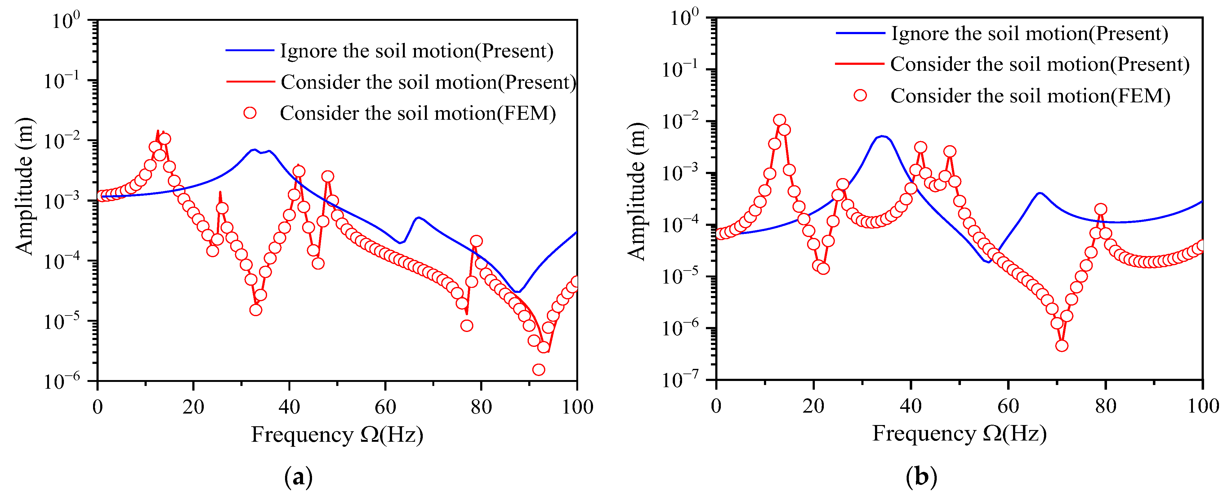
To confirm the theory is also applicable to multi-span continuous beams, the theoretical calculations are contrasted with the outcomes obtained from numerical simulations. Due to the rise in the quantity of beam spans, their mutual operation forms become complicated accordingly. To not lose generality, the article selects a two-span beam for specific analysis. Based on the parameter values outlined in Table 1, the two-span continuous beam model depicted in Figure 2 is selected for consideration. The first span is the direct excitation span under load and the second is the indirect influence span without load excitation. The system damping is characterized using the Rayleigh damping coefficient. In the process of modeling, following the attenuation characteristics of the vertical displacement of the foundation, the motion effect of the soil is equivalent to the additional mass on the continuous beam. The corresponding program is written to establish the numerical simulation model by using the ANSYS software(Mechanical APDL 2023 R1), and the complete method in the finite element method (FEA) is used to analyze the harmonic response. Meanwhile, the theoretical calculations are performed using MATLAB 2024a by combining the TMM and RK4 methods. According to the outcomes derived from the theoretical calculation method and FEM, Figure 3 shows the amplitude-frequency curves in the middle of each span of the two-span continuous beam. The graphs produced by both methods are highly similar, thus verifying the applicability of this theory to continuous beams. Additionally, Figure 3 shows that the inertial motion of the soil with finite depth significantly enhances the displacement resonance characteristics of the two-span continuous beam, making the vibration performance of the continuous beam structure more complicated. Therefore, it is essential to investigate the effect of foundation response with finite-thickness on the continuous beams’ dynamic response.

5. Results and Discussion

This section focuses on the two-span continuous beam model depicted in Figure 2, utilizing the parameter values outlined in Table 1. An extensive analysis is conducted to assess the impact of various parameters, including soil thickness, viscous damping coefficient of the soil, subgrade reaction coefficient, and span ratio, on the mid-span deflection of each span of a continuous beam. The objective is to gain insights into how the finite depth foundation response impacts the resonant response of the continuous beam.

5.1. Effect of Soil Thickness

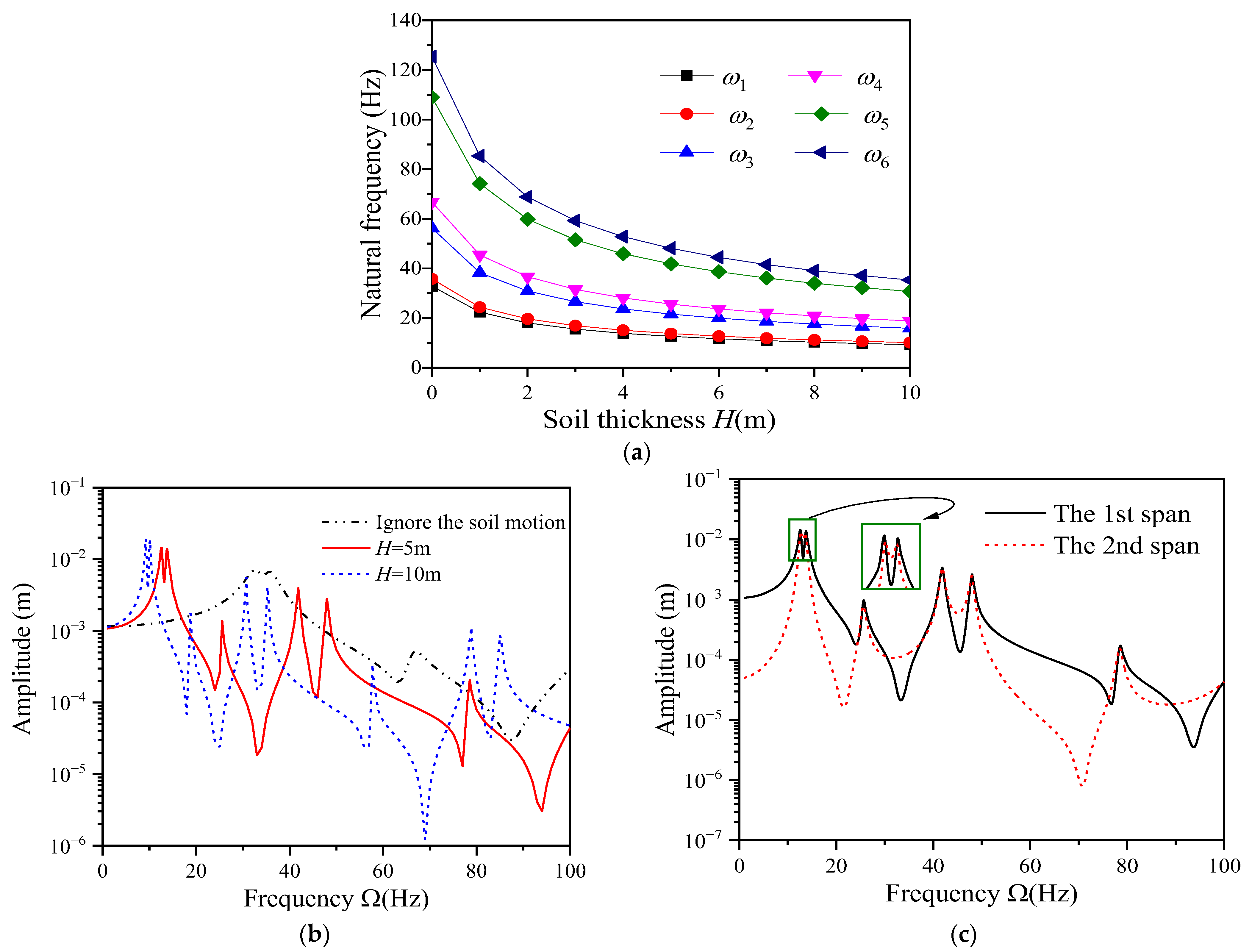
Figure 4a illustrates the relationship between soil depth and the first six natural frequencies of the two-span continuous beam. As the soil depth increases, the system’s natural frequency decreases significantly, and the deeper soil motion has little effect on the change of natural frequency. This observation can be attributed to the increase in the half-wave period of the system’s vibration response due to the finite depth soil’s inertial motion. Figure 4b,c depict the amplitude-frequency curves of the mid-span displacement for two-span continuous beams. Figure 4b reveals that as soil thickness increases, the system’s resonant frequency decreases significantly, leading to an increase in displacement resonance amplitude. On the other hand, Figure 4c shows the displacement resonance amplitudes at each span of the continuous beam are relatively close. When the excitation frequency is lower than the resonant frequency of the first-order system, the amplitude at the second span is less affected by the load excitation effect at the first span.
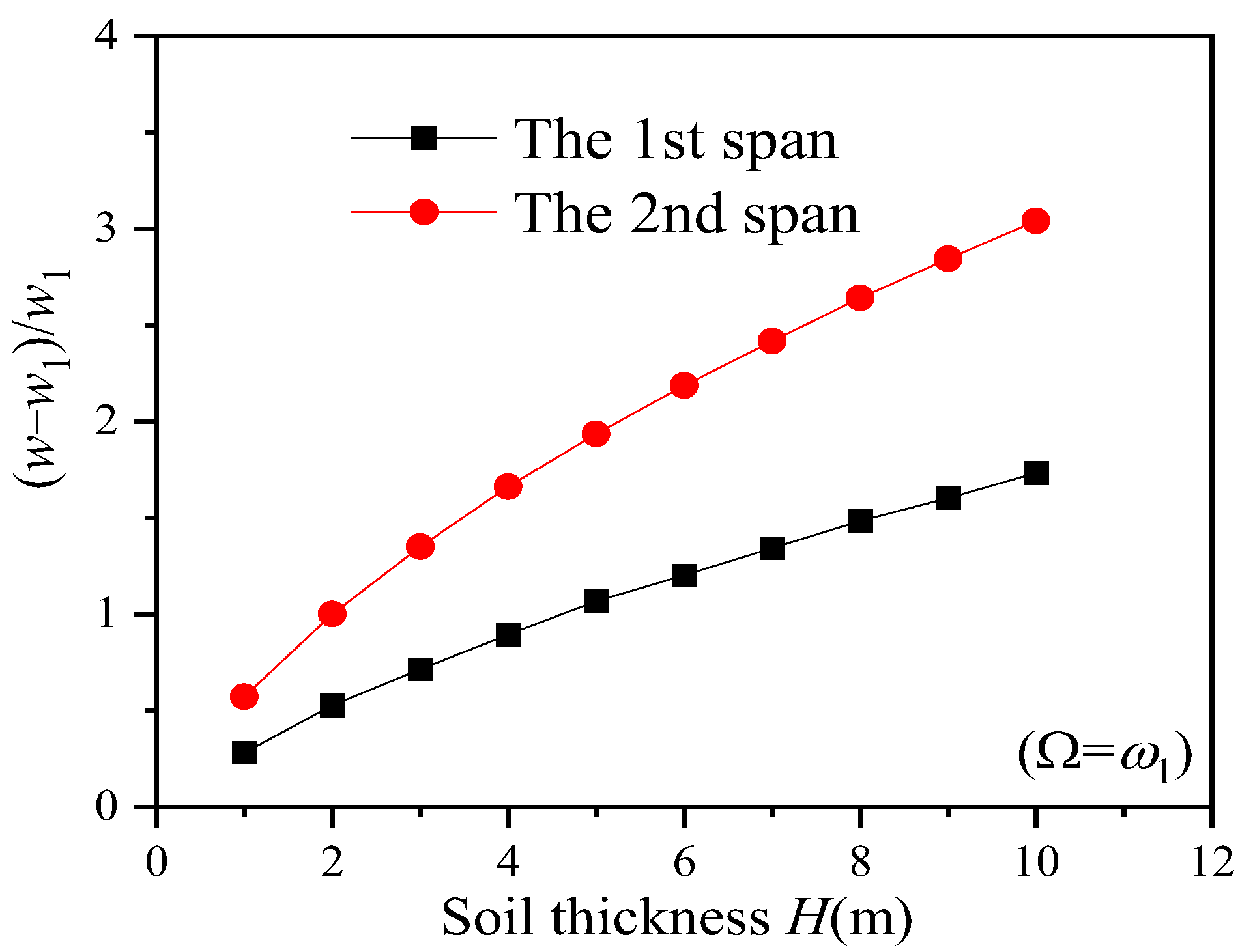
Figure 5 illustrates the enhancement effect of soil depth on the first-order resonance amplitude of each span of the two-span continuous beam. w 1 represents the displacement resonance amplitude of each span when considering the fi-nite depth of the soil. As the soil depth increases, the resonance amplitude of the second span experiences a significantly greater increase compared to the first span. This empha-sizes that the influence of soil depth on the amplitude of the second span is stronger than that of the first span. This observation can be attributed to the suppression of the inertial motion of soil with finite depth by external excitation. Furthermore, it indicates that the soil depth has a lower enhancement effect on the displacement resonance amplitude of the beam span subject to direct excitation compared to the beam span influenced indirectly.

5.2. Effect of the Viscous Damping Coefficient of the Soil

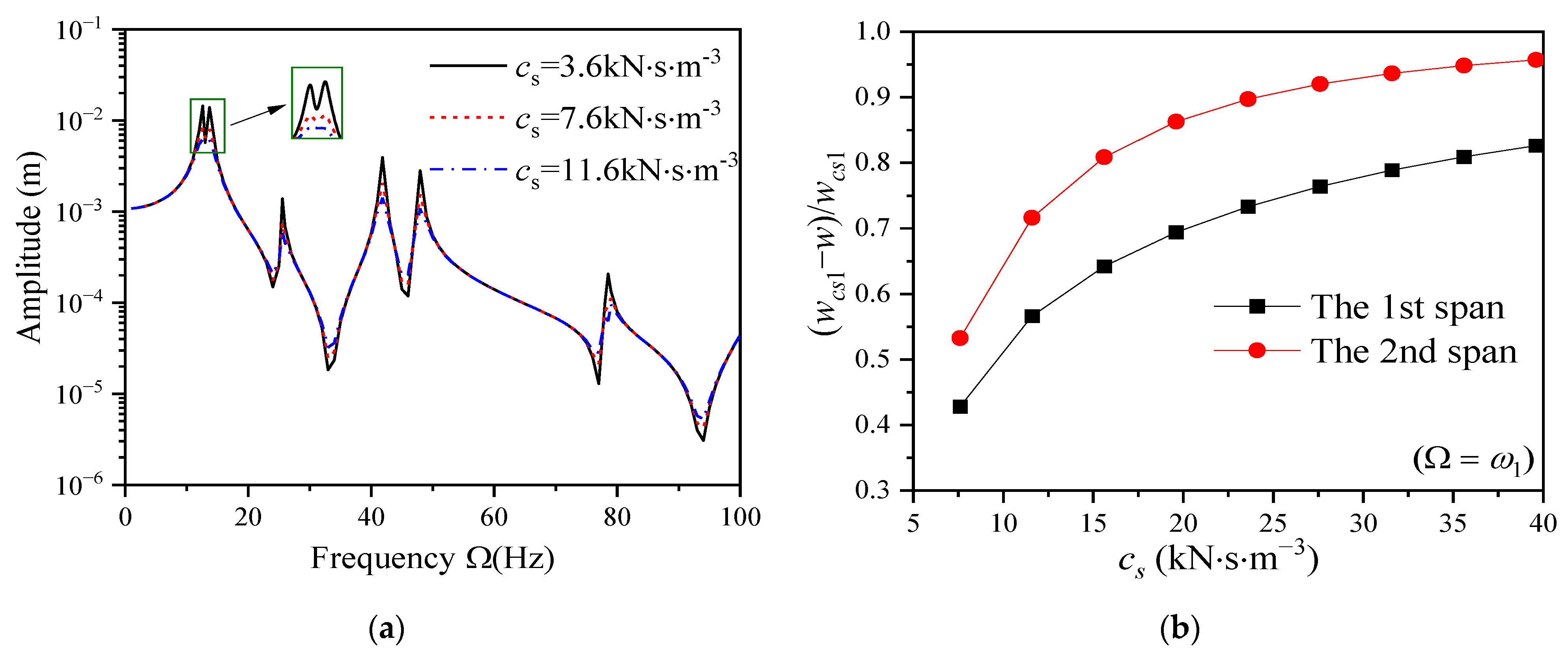
The viscous damping coefficient of the soil is the only variable; according to the parameters in Table 1, c s = 3.6   kN s m 3 , 7.6   kN s m 3 , and 11.6   kN s m 3 are selected for analysis. Figure 6 shows the effect of the c s on the displacement of a two-span continuous beam. Figure 6a presents the impact of the viscous damping coefficient of the soil on the displacement response amplitude of the first span of a continuous beam. For the low damping system, as the increase of viscous damping coefficient of the soil, the displacement resonance amplitude decreases significantly, and the suppression of the non-resonance amplitude is weak. Based on the resonance amplitude w c s 1 generated by c s = 3.6   kN s m 3 , Figure 6b depicts the suppressing effect of the first-order resonant amplitude of each span by the viscous damping coefficient of the soil. The inhibition of the displacement resonance amplitude of the second span by c s is significantly stronger than that of the first span, indicating that the suppression effect of the viscous damping coefficient of the soil on the indirect influence span is significantly stronger than that of the direct excitation span.

5.3. Effect of Subgrade Reaction Coefficient

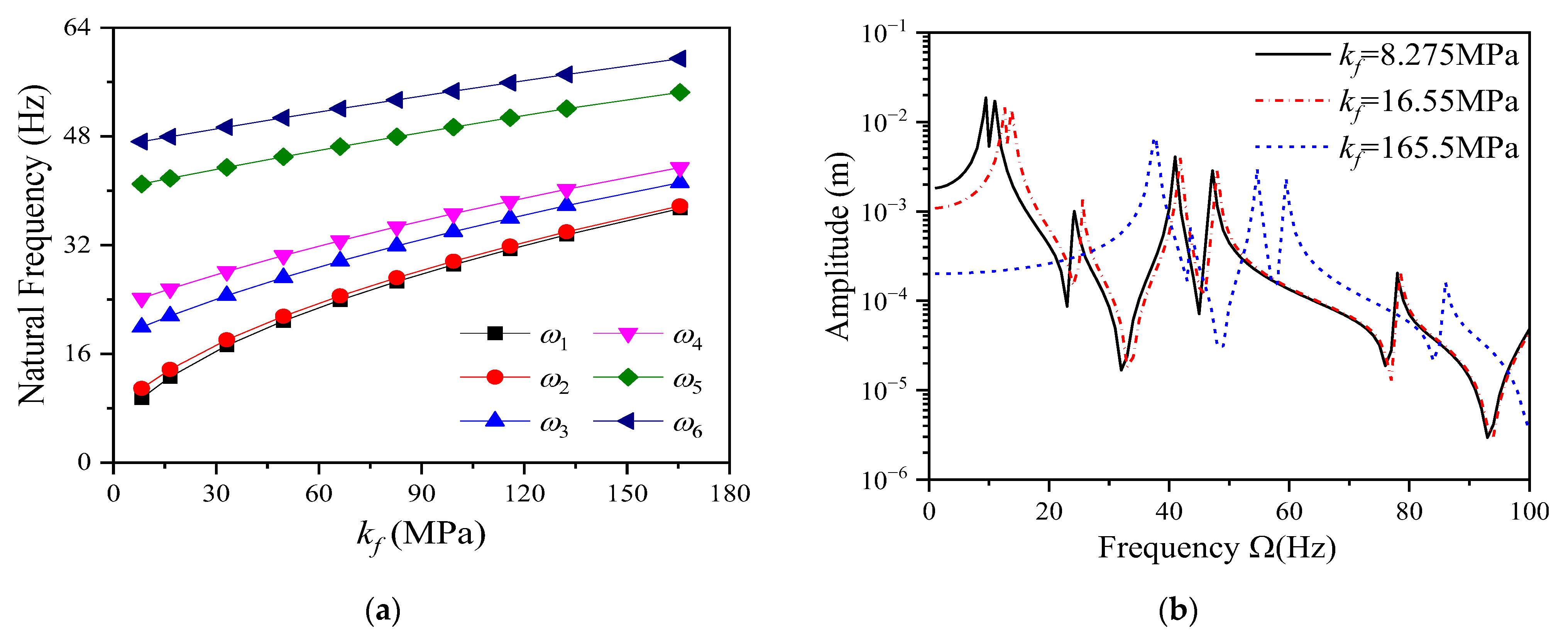
The impact of the subgrade reaction coefficient on the system’s first six natural frequencies is graphically represented in Figure 7a. The natural frequency rises considerably as k f increases, and compared with the influence on higher-order natural frequencies, lower-order frequencies are more significant. According to the parameter values in Table 1, k f = 8.275 MPa, 16.55 MPa, 33.1 MPa, and 165.5 MPa are selected. Figure 7b is the impact of the foundation reaction coefficient on the amplitude-frequency response curve at the middle of the first span. As the subgrade reaction coefficient increases, the amplitude of the displacement response decreases significantly, and the resonance frequency increases. Among these changes, the first and second-order resonance characteristics exhibit the most pronounced variations.
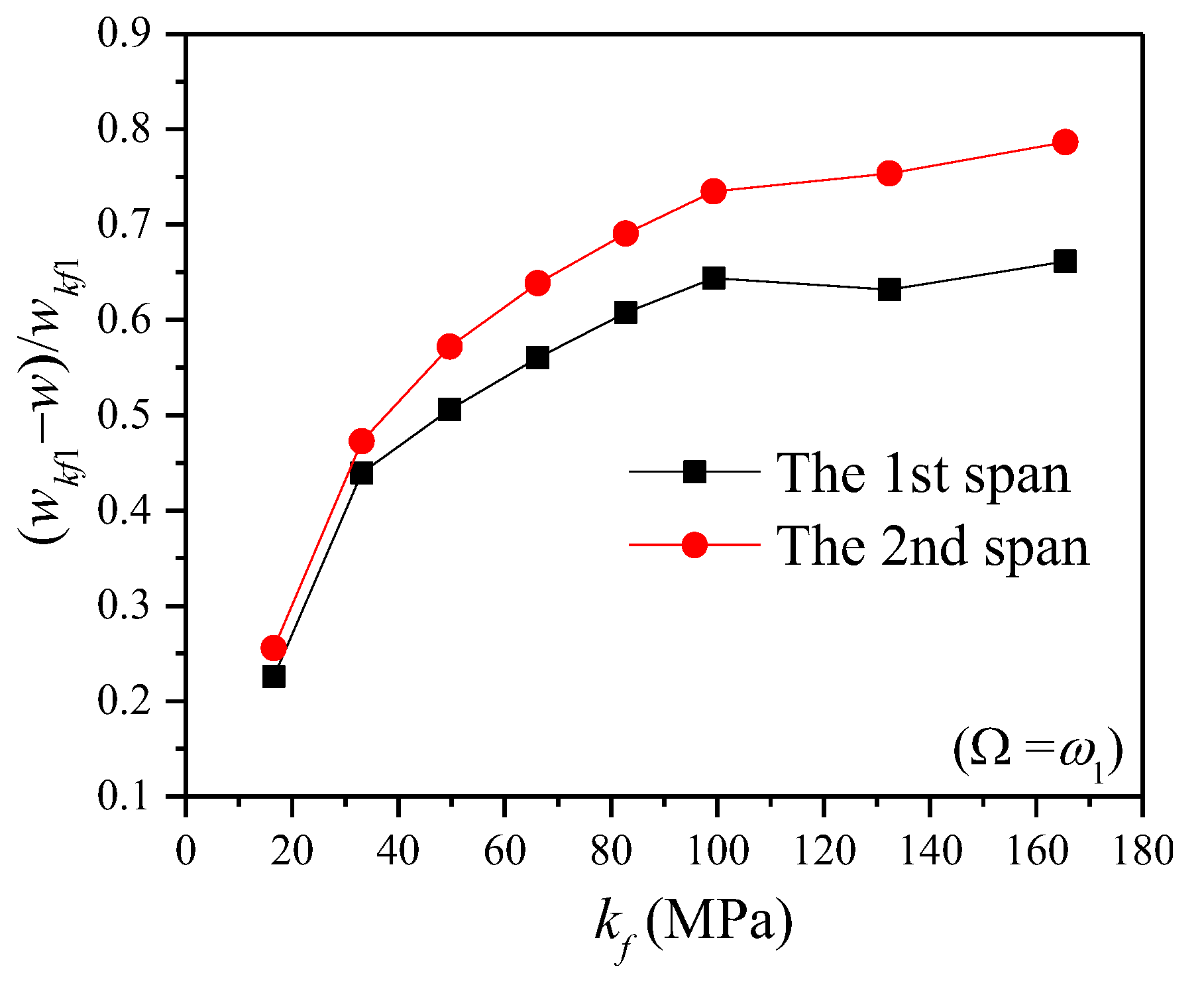
The displacement resonance amplitude difference between different subgrade reaction coefficients and w k f 1 ( k f = 8.275 MPa) is selected. Figure 8 shows the suppressing degree of the subgrade reaction coefficient on the displacement resonance amplitude ( Ω = ω 1 ) of a two-span beam. As shown in Figure 8, the difference curve of the resonance amplitude reflects that the subgrade reaction coefficient has the same suppression trend on the resonance amplitude of each span. Compared to the first span, the subgrade reaction coefficient exerts a more pronounced influence on the second span. This indicates that the suppressive impact of the subgrade reaction coefficient on the indirectly influenced span is significantly stronger than its impact on the directly excited span. The main reason is that the direction of load excitation is opposite to that of the foundation reaction.

5.4. Effect of Span Ratio

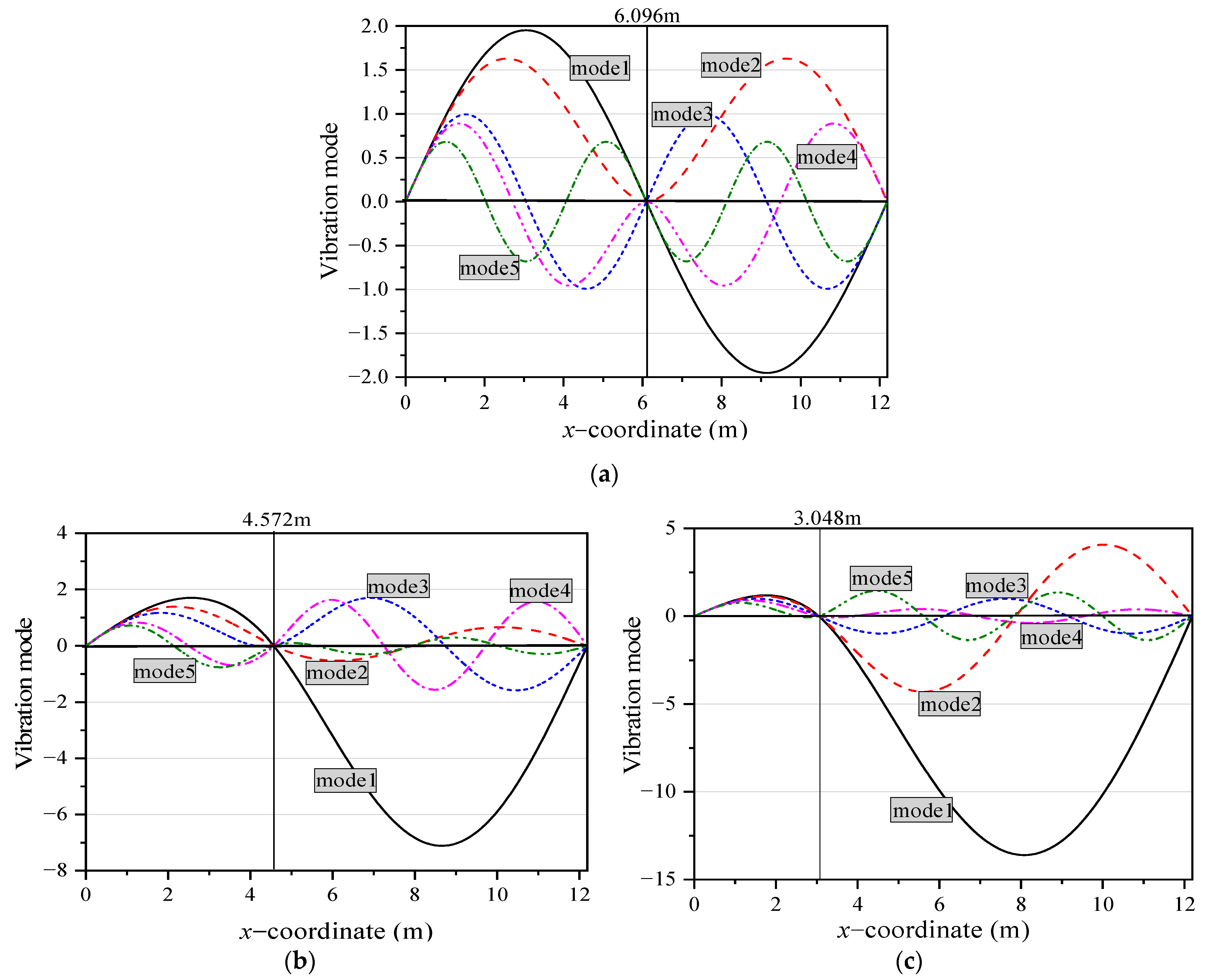
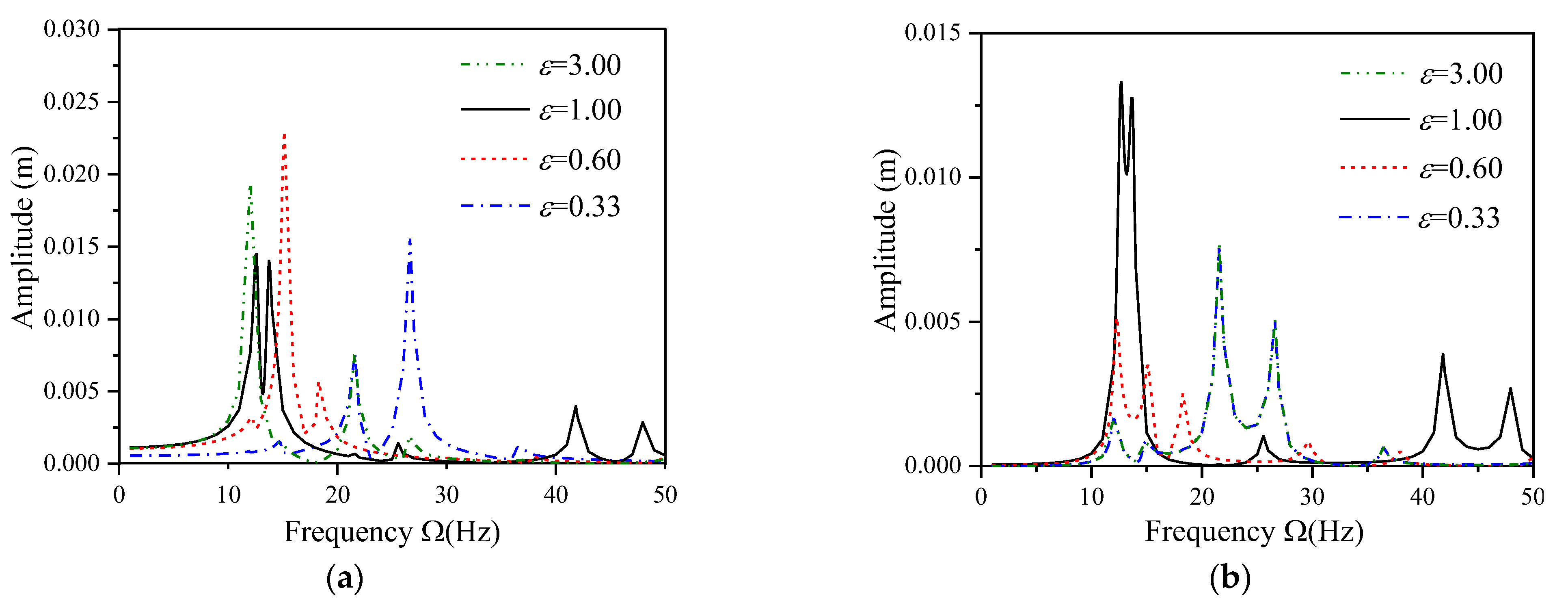
The span ratio of the first span to the second span is defined as ε = l 1 / l 2 . According to the parameter values in Table 1, select ε = 1 (6.096 m + 6.096 m), 0.6 (4.572 m + 7.620 m), 0.33 (3.048 m + 9.144 m). The span ratio’s effect on the mode of a two-span continuous beam is shown in Figure 9. As the span ratio decreases, the mode changes significantly. The wave number of the short-span mode drops, while the wave number will increase in the long-span mode. Compared with asymmetric structures, even-order modes of symmetric structures always have the least half-wave number, while the minimum half-wavelength of odd-order modes is always the longest.
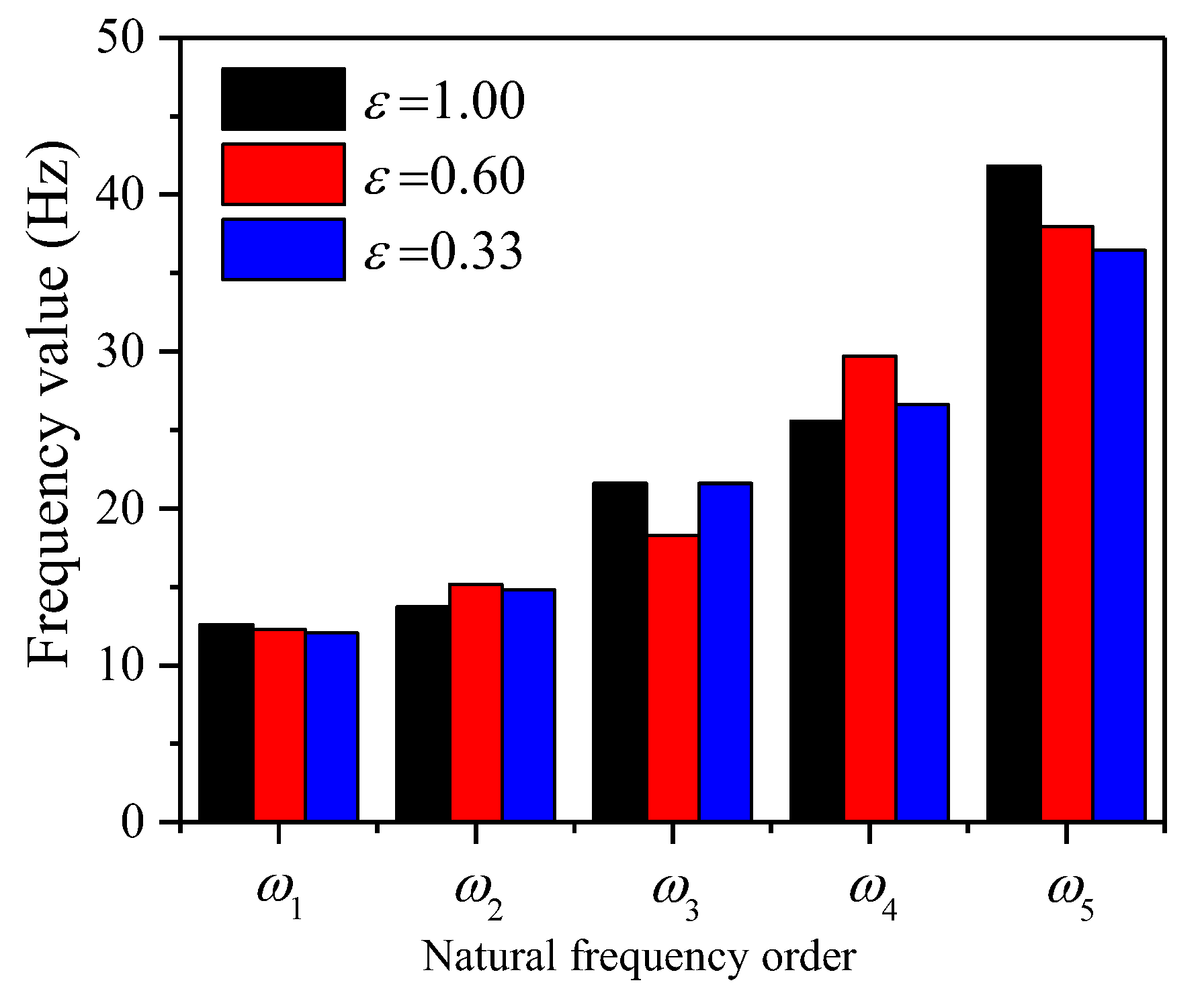
Figure 10 further shows the effect of different span ratios on the natural frequency. As shown in Figure 10, the span ratio impacts the natural frequency of different orders differently. When ε = 1.00, compared with other span ratios, the natural frequency value of the odd-order mode is the largest, the natural frequency value of the even-order mode is the smallest. The reason is related to the half-wave number and the minimum half-wavelength of each mode in Figure 9.
Figure 11 shows the amplitude-frequency curves of the two-span beams with different span ratios. When ε 1 , the structure is transformed into an asymmetric system, the difference between the continuous beam’s first and second resonance rises significantly. With the decrease in span ratio, the half-wave number of the first span structure decreases, which leads to the maximum response amplitude moving to the high-order resonance. While the half-wave number of the second span structure increases, which leads to the resonance frequency of the maximum displacement amplitude decreasing compared with the first span. The amplitude-frequency curves of the second span ε = 3.00 and ε = 0.33 are almost coincident, indicating that the span ratio determines the resonance characteristics that load indirectly affect the beam span.

6. Conclusions

This study has conducted a detailed investigation into the impact of the finite depth foundation response on the vibration characteristics of continuous beams. By integrating the response of the finite depth foundation into a coupled model of a multi-span continuous beam resting on the elastic foundation, the study combines the Timoshenko beam theory with the motion theory of elastic foundations. The numerical solution of this coupled model is obtained using the transfer matrix method (TMM) and the fourth-order Runge-Kutta method (RK4). Taking a two-span continuous beam as a representative case, the study analyzes the influence of soil thickness, viscous damping coefficient of the soil, subgrade reaction coefficient, and span ratio on the vibration response of the continuous beam. The following conclusions can be explicitly drawn from the results and discussions presented in this research:
  • As the thickness of the soil involved in the movement increases, the continuous beam’s natural frequency will decrease, and the resonance amplitude increases significantly. When comparing the dynamic responses of different beams, the enhancement impact of finite depth soil motion on the response amplitude of the indirect excitation beam section is more significant than that of the direct excitation beam section.
  • The viscous damping coefficient of the soil and the coefficient of subgrade reaction have a greater inhibition effect on the indirect influence span than on the direct excitation span. As the coefficient of the subgrade reaction increases, the system’s natural frequency increases, and the resonant response amplitude decreases.
  • The adjustment of the span ratio has a significant influence on the dynamic response of the multi-span beam system. (1) Compared with other span ratios, the odd-order natural frequency is the largest and the even-order natural frequency is the smallest when ε = 1.00 . (2) The smaller the span ratio is, the more pronounced the increasing effect of the resonant frequency is. (3) When the span ratio is determined, no matter whether the load acts on the long span or the short span, the response amplitude of the beam span indirectly affected by the load is certain.
In this paper, the model presented is limited to the dynamic response analysis of multi-span continuous beams on a linearly elastic, idealized Winkler foundation. It does not consider cases such as non-uniform beams, nonlinear soil behavior, and multiple excitation sources. Additionally, there are certain limitations in using the vertical displacement attenuation function derived from the Vlasov foundation model to incorporate finite depth soil movement into the Winkler elastic foundation model. To advance research and application in this field, it is necessary to continue modeling studies of beams on elastic foundations under complex foundation conditions. This will aim to accurately analyze the dynamic characteristics of beams on finite depth foundations.

Author Contributions

Conceptualization, D.L. and J.M.; methodology, D.L. and J.M.; software, J.W. and Y.G.; validation, D.L., H.Y. and J.W.; formal analysis, D.L. and J.M.; investigation, J.W. and C.W.; resources, D.L. and J.M.; data curation, D.L., H.Y. and J.W.; writing—original draft preparation, D.L.; writing—review and editing, D.L. and H.Y.; visualization, D.L.; supervision, D.L.; project administration, J.M.; funding acquisition, D.L. and J.M. All authors have read and agreed to the published version of the manuscript.

Funding

This article was funded by the National Natural Science Foundation of China (Grant No. 11502072), the National Key R&D Project: Research and Development of Intelligent Interconnected Equipment Network Collaborative Manufacturing/Operation and Maintenance Integration Technology and Platform (Grant No. 2020YFB1712105), the National Key R&D Project: Theory and Method of Underground Space Development and Construction (Grant No. 2019YFC0605104), and the Key R&D and Promotion Special Project in Henan Province-Science and Technology Research (joint fund) Project (Grant No. 232103810082).

Informed Consent Statement

Not applicable.

Data Availability Statement

Data is contained within the article.

Conflicts of Interest

The authors declare no conflicts of interest.

References

  1. Hayashikawa, T.; Watanabe, N. Free vibration analysis of continuous beams. J. Eng. Mech. 1985, 111, 639–652. [Google Scholar] [CrossRef]
  2. Busool, W.; Eisenberger, M. Vibrations of axially loaded continuous beams. Int. J. Struct. Stab. Dyn. 2002, 2, 117–133. [Google Scholar] [CrossRef]
  3. Lee, J. Eigenvalue analysis of double-span Timoshenko beams by pseudospectral method. J. Mech. Sci. Technol. 2005, 19, 1753–1760. [Google Scholar] [CrossRef]
  4. Tullini, N.; Tralli, A.; Baraldi, D. Stability of slender beams and frames resting on 2D elastic half-space. Arch. Appl. Mech. 2013, 83, 467–482. [Google Scholar] [CrossRef]
  5. Seetapan, P.; Chucheepsakul, S. Dynamic responses of a two-span beam subjected to high speed 2DOF sprung vehicles. Int. J. Struct. Stab. Dyn. 2020, 6, 413–430. [Google Scholar] [CrossRef]
  6. Wang, Y.J.; Wei, Q.C.; Yau, J.D. Interaction response of train loads moving over a two-span continuous beam. J. Struct. Stab. Dyn. 2013, 13, 1350002. [Google Scholar] [CrossRef]
  7. Wang, L.; Kang, X.; Jiang, P. Vibration analysis of a multi-span continuous bridge subject to complex traffic loading and vehicle dynamic interaction. KSCE J. Civ. Eng. 2016, 20, 323–332. [Google Scholar] [CrossRef]
  8. Tamaddon, S.; Hosseini, M.; Vasseghi, A. Effect of non-uniform vertical excitations on vertical pounding phenomenon in continuous-deck curved box girder RC bridges subjected to near-source earthquakes. J. Earthq. Eng. 2022, 26, 5360–5383. [Google Scholar] [CrossRef]
  9. Lee, S.M. Analysis of center frequency effect on damping parameters estimation using continuous wavelet transform. KSCE J. Civ. Eng. 2021, 25, 1399–1409. [Google Scholar] [CrossRef]
  10. Timoshenko, S. Vibration Problems in Engineering; Wiley: New York, NY, USA, 1974; pp. 309–312. [Google Scholar]
  11. Deng, H.Y.; Jin, X.Y.; Gu, M. A simplified method for evaluating the dynamic properties of structures considering soil–pile–structure interaction. Int. J. Struct. Stab. Dyn. 2018, 18, 1871005. [Google Scholar] [CrossRef]
  12. Bao, T.; Liu, Z. Evaluation of Winkler model and Pasternak model for dynamic soil-structure interaction analysis of structures partially embedded in soils. Int. J. Geomech. 2020, 20, 04019167. [Google Scholar] [CrossRef]
  13. Asadijafari, M.H.; Zarastvand, M.R.; Talebitooti, R. The effect of considering Pasternak elastic foundation on acoustic insulation of the finite doubly curved composite structures. Compos. Struct. 2021, 256, 113064. [Google Scholar] [CrossRef]
  14. Smith, J.; Brown, A. Analysis of Continuous Beams in Modern Bridge Construction. J. Struct. Eng. 2022, 148, 567–580. [Google Scholar] [CrossRef]
  15. Lee, C.; Kim, D. Vibration Analysis of Continuous Beams on Elastic Foundations. Int. J. Civ. Eng. 2021, 19, 345–356. [Google Scholar]
  16. Zhang, X.; Li, Y. Case Studies on the Performance of Continuous Beams Supported by Soil. Geotech. Eng. J. 2023, 54, 210–225. [Google Scholar]
  17. Miller, R.; Thompson, P. Structural Behavior of Continuous Beams Under Varying Soil Conditions. Civ. Eng. Res. 2020, 77, 92–108. [Google Scholar]
  18. Rades, M. Dynamic analysis of an inertial foundation model. Int. J. Solids Struct. 1972, 8, 1353–1372. [Google Scholar] [CrossRef]
  19. Jaiswal, O.R.; Iyengar, R.N. Dynamic response of a beam on elastic foundation of finite depth under a moving force. Acta Mech. 1993, 96, 67–83. [Google Scholar] [CrossRef]
  20. Metrikine, A.V.; Popp, K. Steady-state vibrations of an elastic beam on a visco-elastic layer under moving load. Arch. Appl. Mech. 2000, 70, 399–408. [Google Scholar] [CrossRef]
  21. Ma, J.J.; Liu, F.J.; Nie, M.Q.; Wang, J.B. Nonlinear free vibration of a beam on Winkler foundation with consideration of soil mass motion of finite depth. Nonlinear Dyn. 2018, 92, 429–441. [Google Scholar] [CrossRef]
  22. Chen, G.L.; Zeng, X.Y.; Liu, X.B.; Rui, X.T. Transfer matrix method for the free and forced vibration analyses of multi-step Timoshenko beams coupled with rigid bodies on springs. Appl. Math. Model. 2020, 87, 152–170. [Google Scholar] [CrossRef]
  23. Wang, Q.F.; Wang, L.Y.; Liu, Q.S. Seismic response of stepped frame-shear wall structures by using numerical method. Comput. Method. Appl. Mech. Eng. 1999, 173, 31–39. [Google Scholar] [CrossRef]
  24. Vallabhan, C.V.G.; Das, Y.C. Parametric study of beams on elastic foundation. J. Eng. Mech. 1988, 114, 2072–2082. [Google Scholar] [CrossRef]
  25. Rui, X.T.; Zhang, J.S.; Zhou, Q.B. Automatic deduction theorem of overall transfer equation of multibody system. Adv. Mech. Eng. 2014, 6, 378047. [Google Scholar] [CrossRef]
  26. Thambiratnam, D.; Zhuge, Y. Free vibration analysis of beams on elastic foundation. Comput. Struct. 1996, 60, 971–980. [Google Scholar] [CrossRef]
  27. Friswell, M.I.; Adhikari, S.; Lei, Y. Vibration analysis of beams with non-local foundations using the finite element method. Int. J. Numer. Meth. Eng. 2007, 71, 1365–1386. [Google Scholar] [CrossRef]
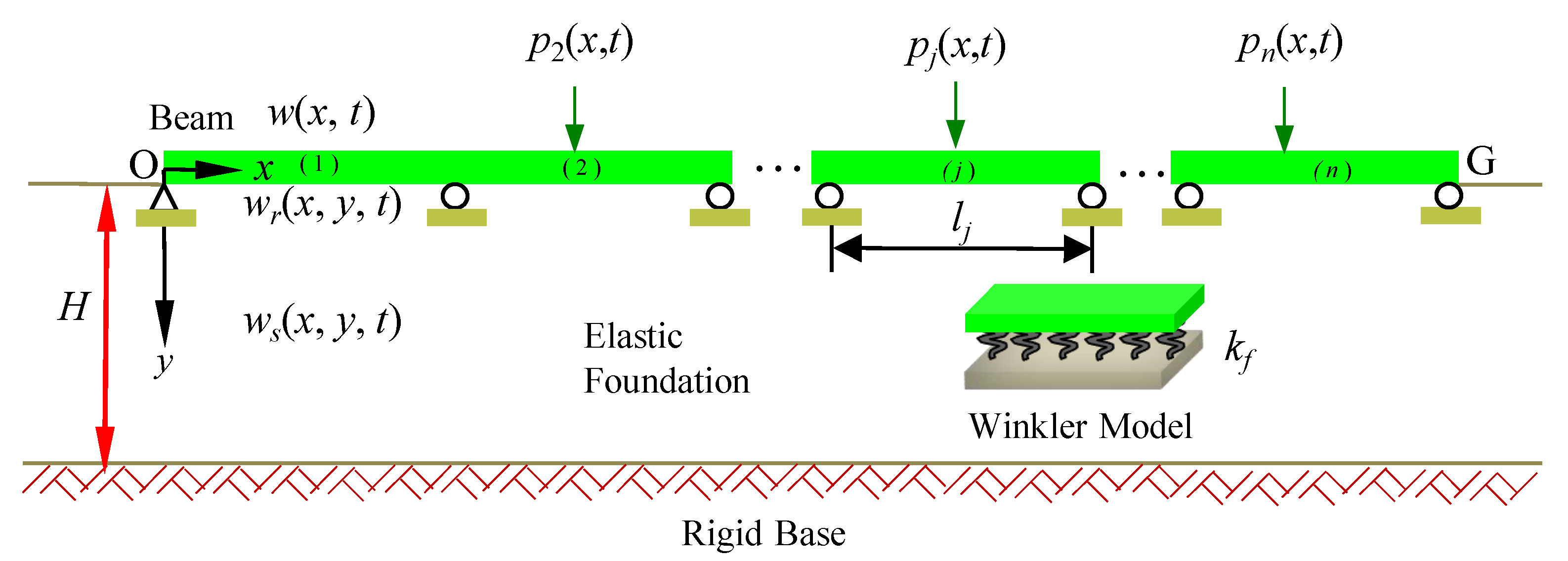
Figure 1. Continuous beam supported on soil with finite depth.
Coatings 14 00864 g001
Figure 2. Two-span continuous beam model with simply supported boundary.
Coatings 14 00864 g002
Figure 3. Amplitude-frequency curves at each span’s mid-span of a two-span continuous beam: (a) the first span; (b) the second span.
Coatings 14 00864 g003
Figure 4. Effect of soil thickness on a two-span continuous beam: (a) natural frequency; (b) the first span; (c) H = 5 m.
Coatings 14 00864 g004
Figure 5. The enhancement effect of soil thickness on the displacement of two-span continuous beam.
Coatings 14 00864 g005
Figure 6. Impact of viscous damping coefficient of the soil on displacement of a two-span continuous beam: (a) the first span; (b) inhibition effect of each span.
Coatings 14 00864 g006
Figure 7. Impact of subgrade reaction coefficient on vibration response of a two-span continuous beam: (a) natural frequency; (b) mid-span of the first span.
Coatings 14 00864 g007
Figure 8. The suppressing impact of subgrade reaction coefficient on displacement of a two-span continuous beam.
Coatings 14 00864 g008
Figure 9. Modal effect of span ratio on a two-span continuous beam: (a) 6.096 m + 6.096 m (ε = 1.00); (b) 4.572 m + 7.62 m (ε = 0.60); (c) 3.048 m + 9.144 m (ε = 0.33).
Coatings 14 00864 g009
Figure 10. Effect of span ratio on the natural frequency of the two-span beam.
Coatings 14 00864 g010
Figure 11. Effect of span ratio on response amplitude of a two-span continuous beam: (a) mid-span of the first span; (b) mid-span of the second span.
Coatings 14 00864 g011
Table 1. Physical parameters of the beam and foundation.
Physical MeaningSymbolUnitNumerical Value
The jth span length of a continuous beam l j m 6.096
The beam’s width b m 0.61
The beam’s height h m 0.305
The per unit length beam’s mass m kg m 1 447.08
Damping factor per unit length c kN s m 2 1.0
Moment of inertia of the per unit length beam γ kg m 3.466
Young’s modulus of the beam E MPa 2.482 × 10⁴
Poisson ratio of the beam ν 0 ——0.25
Soil mass per unit thickness of the per unit length beam ρ s kg m 2 1037
Viscous damping coefficient of the soil per unit thickness of the per unit length beam c s kN s m 3 3.6
Modulus of subgrade reaction k f MPa 16.55
Soil thickness H m 5
Table 2. Natural frequency of the simply supported beam on an elastic foundation.
Natural Frequency (Hz)(Timoshenko S., 1974) [10](Thambiratnam and Zhuge, 1996) [26](Friswell et al., 2007) [27]The Present Study
Euler-BernoulliTimoshenko
ω 1 32.906332.903332.89832.874932.8289
ω 2 56.813556.819356.80856.804056.1037
ω 3 112.908111.961111.900111.9186108.303
ω 4 193.760193.8085182.7608
Disclaimer/Publisher’s Note: The statements, opinions and data contained in all publications are solely those of the individual author(s) and contributor(s) and not of MDPI and/or the editor(s). MDPI and/or the editor(s) disclaim responsibility for any injury to people or property resulting from any ideas, methods, instructions or products referred to in the content.